Series 3000 Engineers Manual. - FGH Controls Limited · PDF file · 2008-02-06ii...
52
Engineers Manual Series 3000 FGH Controls Ltd Openshaw Way,Letchworth Herts. SG6 3ER Tel: (01462) 686677 Fax: (01462) 480633 1 2 OP SP SEG EVNT FGH Series 3000 Programmer HOLD FAST START STOP PROG MAN REM AL1 AL2 TUNE TALK
Transcript of Series 3000 Engineers Manual. - FGH Controls Limited · PDF file · 2008-02-06ii...

Engineers Manual
Series 3000
FGH Controls LtdOpenshaw Way,LetchworthHerts. SG6 3ERTel: (01462) 686677Fax: (01462) 480633
12OP
SPSEGEVNT
FGH Series 3000 Programmer
HOLD FAST START STOP PROG
MAN REM AL1 AL2 TUNE TALK


Contents i
M45 Issue 1.6
Contents.
SECTION A - GENERAL................................11.0 Introduction ...................................................... 11.1 Displays ........................................................... 11.2 Status indicators .............................................. 21.3 Bargraph.......................................................... 22.0 Buttons............................................................. 33.0 Short scroll....................................................... 34.0 Long scrolls...................................................... 44.1 Entry and exit................................................... 44.2 Controller long scroll........................................ 4
4.2.1 Parameter groups ...................................... 44.3 Programmer long scroll ................................... 65.0 Passwords ....................................................... 85.1 general............................................................. 85.2 Factory settings ............................................... 85.3 Setting the password....................................... 85.4 Setting the scope............................................. 8
SECTION B - SOFTWARECONFIGURATION ...............................10
6.0 General .......................................................... 106.1 E Mode .......................................................... 106.2 Lock mode..................................................... 107.0 Emode parameter groups ............................. 107.1 Input 1 Group 'IP1'......................................... 11
7.1.1 Input type................................................. 117.1.2 Cold junction compensation.................... 127.1.3 Input high and low scalars....................... 127.1.4 High and low setpoint limits..................... 127.1.5 Decimal point........................................... 127.1.6 Input Bias................................................. 12
7.2 Controller Group 'Contr'................................. 137.2.1 Control format.......................................... 137.2.2 Control action .......................................... 137.2.3 Thermal Head Ratio mode...................... 137.2.4 Gain scheduling....................................... 137.2.5 Tuner response ....................................... 14
7.3 Failure Safety Group ‘FSAFE’...................... 147.3.1 Failure safety on/off switch...................... 157.3.2 High safety limit ....................................... 157.3.3 Low safety limit ........................................ 15
7.4 Profiler Group ‘ProF’ (P3000 only). .............. 157.4.1 Number of profiler channels.................... 157.4.2 Channel 2 servo function. ....................... 157.4.3 Channel 2 setpoint limits. ........................ 157.4.4 Channel 2 decimal point.......................... 157.4.5 Number of profiles................................... 157.4.6 Synchronising 2 profiler channels ........... 157.4.7 Disabling the delayed start ...................... 167.4.8 Disabling profile repeats.......................... 16
7.5 Input/Output Group 'IO' ................................. 167.5.1 Slots 1 to 5................................................ 167.5.2 Time proportional output type .................. 177.5.3 Constant cycle TP minimum on time...... 18
7.5.4 Live and True zero analogue controloutputs ................................................. 18
7.5.5 Input 2 types ............................................ 197.6 Digital input Group 'dinS' .............................. 19
7.6.1 Digital inputs ............................................ 197.7 Alarms Group 'ALrS'...................................... 21
7.7.1 Alarms in general .................................... 217.7.2 Alarm sense and latching........................ 217.7.3 Alarm type ............................................... 217.7.4 Alarm hysteresis...................................... 217.7.5 Unlatching alarms .................................... 22
7.8 Input 2 Group 'IP2'......................................... 227.8.1 Remote inputs in general ........................ 227.8.2 Remote input point type .......................... 237.8.3 Remote input 2 limits............................... 237.8.4 Remote setpoint gain on/off .................... 24
7.9 Retransmission Group 'rEtr' .......................... 247.9.1 Retransmission ........................................ 247.9.2 Retransmission Type ............................... 247.9.3 Retransmission Range............................. 247.9.4 Retransmission parameter....................... 247.9.5 Retransmission limits for analog rtx......... 257.9.6 Retransmission limits for PWM rtx .......... 257.9.7 Retransmission bias................................. 257.9.8 PWM Retransmission Trim...................... 25
7.10 Serial communication Group 'ConS' ........... 257.10.1 Digital serial communications ................ 257.10.2 Digital remote setpoint ON/OFF
switch ................................................... 267.10.3 Digital setpoint retransmission
(P3000 Only)........................................ 26
SECTION C - PROGRAMMING THEPROFILE GENERATOR......................28
8.0 General .......................................................... 288.1 Start sequence .............................................. 288.2 Supply interruption......................................... 308.3 Hold condition................................................ 318.4 Ending a profile.............................................. 338.5 Repeating the profile ..................................... 338.6 Chaining profiles............................................ 338.7 Delay start timer............................................. 34
SECTION D - HARDWARECONFIGURATION...............................35
9.0 General .......................................................... 359.1 Gaining access to the option boards............. 359.2 Fitting the options board carrier..................... 35
9.2.1 Transmitter power supply......................... 359.3 Broken sensor drive selection....................... 3610.0 Options boards ............................................ 3610.1 Relay board PC1542 .................................. 3610.2 Remote setpoint board PC1543................. 3610.3 Analogue output board PC1544................. 3710.4 Slide wire input board PC1545................... 37

ii Series 3000 Engineers Manual
M45 Issue 1.6
10.5 Digital serial communications board PC1541 ......................................................... 37
10.6 Isolated logic drive and External eventdriver board PC1549.................................... 37
10.7 Remote program select input boardPC1543A....................................................... 37
11.0 Slot availability ............................................. 3812.0 Part number coding..................................... 38
SECTION E - CALIBRATION ......................4213.0 General ....................................................... 4213.1 Preparation .................................................. 4213.2 Main input .................................................... 42
13.2.1 Main input span...................................... 4213.2.2 Resistance span..................................... 4313.2.3 Span adjustment for external signal
conditioning.......................................... 4313.3 Cold junction zero........................................ 4313.4 Remote set point input calibration............... 4313.5 Slidewire input calibration............................ 4413.6 Remote program selection input
(P3000 only) .................................................. 4513.7 Analogue output calibration......................... 45
Appendix A - Fault codes..............................47

A: General 1
M45 Issue 1.6
SECTION A - GENERAL
1.0 Introduction
This manual is designed to be read by an engineer configuring the P3000programmer or S3000 Controller to customer requirements before delivering a newinstrument, or the reconfiguring of an existing instrument to accommodate newrequirements. It covers selection and fitting of option boards, hardware configurationof these boards with patch links, and software configuration and calibration of theinstruments programmer and controller parameters.
The task of installing the S3000/P3000 is covered in a separate installation manualprovided with the instrument. Also, the installation, configuration and use of theserial communications option is covered by the Series 3000 communicationsmanual.
Series 3000 FRONT PANEL
1.1 DisplaysThe main display on the S3000/P3000 normally shows the process variable, whilethe lower display parameter is shown by the illuminated mode indicator; setpoint,output, valve position, time, segment or event.
FGH Series 3000 Programmer
12OP
StatusIndicators
ModeIndicators
InstrumentReleaseScrews
Left button
Right button
Upbutton
Downbutton
MainDisplay
LowerDisplay
Bargraph
Starbutton
Auto/Manbutton
SPSEGEVNT
HOLD FAST START STOP PROG
MAN REM AL1 AL2 TUNE TALK

2 Series 3000 Engineers Manual
M45 Issue 1.6
1.2 Status indicatorsThe status indicators provide information on the status of the instrument. Thefollowing is a brief explanation of each of the legends.
1 Heat output is on in time-proportion mode. Not used for analogueoutputs.
2 Cool output is on in time-proportion mode if configured as a heat/coolinstrument. Not used for analogue outputs.
MAN The instrument output is under manual control
REM Currently active setpoint is from a remote source, this may be fromserial communications or analogue into a remote set point cardoption. (S3000 only)
AL1 Alarm 1 is active, if alarms are latched then this indication is alsolatched until cleared.
AL2 As alarm 1, but for alarm 2
TUNE The tuner is currently running.
TALK The instrument is being addressed via serial comms.
1.3 BargraphThe S3000/P3000 is equipped with a bargraph, displaying output. The bargraph isarranged differently for different control types;
AUTO/MANUALAND HEAT ONLY
HEAT/COOL
MOTORISED VALVE
CONTROL TYPE BARGRAPH DISPLAY
100% cool 100% heat
closed open
0% 50% 100%

A: General 3
M45 Issue 1.6
2.0 Buttons
The S3000/P3000 front panel buttons have the following functions:
The right and left buttons are used to select which parameter is tobe displayed on the display. In short scroll these button are alsoused to enter the long scroll or profile scroll.
These buttons are used only to change the value of the parameterselected in the long scrolls or emode, or to change the value ofoutput in the short scroll.
This is the auto/manual changeover button, it is used when theinstrument is in short scroll displaying output
The star button is used to show different information on the maindisplay during calibration (section E), and to unlatch a latched alarmwhen the relevant alarm level in the controller long scroll is being
displayed. The star button is used on the P3000 profile generator to access thealternative functions assigned to each button (HOLD, FAST, STOP, START andPROG). To access these functions, press and hold the star button and then pressthe button above the desired function.
3.0 Short scrollShort scroll is the normal operating condition of the instrument, when the maindisplay is indicating the value of the process variable and the lower display isindicating the value of setpoint, output, valve position, time, segment or eventsdepending on the mode indicator lit, SP, OP, SEG or EVNT.
The function of the lower display may be changed by pressing the ������3 or
��������������4 buttons.
This will proceed forwards or backwards through the short scroll list depending onwhich button is pressed.
SP The current control setpoint.
SP + 1 The current control setpoint for profiler channel 1. Press the star key toview the current segment target level.
SP + 2 The current control setpoint for profiler channel 2. Press the star key toview the current segment target level.
2 The current value of the second measured input if used as MV2.
OP The current controller output in %. Press the A/M button to togglebetween auto and manual modes.
OP+2 For thermal head ratio controllers, shows the current air setpoint.For motorised valve controllers, press the Star key to display the actualvalve position in %.

4 Series 3000 Engineers Manual
M45 Issue 1.6
SEG If a profile is running the lower display shows the current running programand segment number. Press the star key to display the segment elapsedtime in hours and minutes.If no profile is running the lower display shows the currently selectedprofile number. Press Star + A/M to select a new profile number.
EVNT Shows the current event output status.
The short scroll list will only include those parameters that are applicable to thecurrent operating mode of the instrument.
4.0 Long scrollsIn the S3000 controller, the long scroll is a controller scroll. This contains all thecontrol parameters and commissioning data. The P3000 programmer has two longscrolls, the controller scroll, which is the same as the long scroll in the S3000, andthe programmer scroll, which contains all the program data on the ten profilesstored in the P3000.
4.1 Entry and exitTo enter the long scroll of an S3000 Controller, press and hold the left or rightbutton. After a second the display will change to show the mnemonic of the first ofthe long scroll parameters on the lower display and the value of that parameter onthe main display.
To enter the controller scroll on the P3000 Programmer, press and hold the rightbutton. After a few seconds the first parameter group mnemonic of the controllerscroll will be seen on the lower display with the value of that parameter on the upperdisplay.
To enter the programmer scroll on the P3000 Programmer, press and hold the lefthand button. After a few seconds the first programmer parameter, delay, will beshown on the lower display and its value on the upper display.
To exit any long scroll, press and hold the left or right button. After a second thedisplay will change back to that of the short scroll. Alternatively, if no buttons arepressed for about 20 seconds, then the instrument will automatically revert to shortscroll.
4.2 Controller long scrollController long scroll parameters include commissioning PID terms, setpoint andalarm levels. Only relevant parameters are included in the long scroll list, eg. if alarm2 is not used then alarm 2 levels will not be on the long scroll list. Similarly, valveaction time, for example, is only listed if the instrument is configured as a valvepositioner.
4.2.1 Parameter groupsThe controller scroll consists of a large number of parameters, so to improve easeand speed of use, the parameters are presented to the user in groups. At the startof each group, the group name is shown on the lower display with the upper display

A: General 5
M45 Issue 1.6
blank. Pressing the star button will gain access to the parameters within that group.Pressing the scroll button will advance the scroll to the start of the next group.
If the group is entered (by means of the star button), then the parameters are listedin sequence in the usual way when the scroll button is pressed. At the end of thegroup the group name is displayed again. This enables the user to re-enter thesame group again if required.
Some parameter groups are always present ( such as the SP group ), while othersare present only if they contain parameters applicable to the current instrumentconfiguration.
Scroll between parameters within a group using left and right buttons. These are thereverse and forward scroll controls. When the end of the long scroll list is reachedthe list wraps round to the beginning again.
The following is a complete list of the Controller long scroll parameters with theirassociated mnemonics and explanation of contents.
Group Mnemonic Parameter MeaningPASS PASS password entry Password entry. See section 5.SP SPLOC set point local local set point in displayed units
SPL 2 set point local 2 local set point 2 in displayed units for 2 channel profilersS-tyP setpoint type Setpoint to be used
loc Local, set point = SPLOCre Remote, set point is remoteind Indexed, set point is sum of local and remote
setpointlo Remote setpoint is low clamped to SPLOChi Remote setpoint is hi clamped to SPLOC
rAtE setpoint slew rate limit Maximum rate of change of control set point in digits perhour
GAIN remote setpoint gain The measured remote setpoint is multiplied by this GAINvalue before being used for control.
ASP1 aux setpoint 1 Setpoint value selected by digital input 1ASP2 aux setpoint 2 Setpoint value selected by digital input 2
Contr tune tuner on/off On or off, perform one shot tune if onProP default prop band Heating proportional band in % if positive, or on/off
hysteresis in digits if negative.When terms sets are being used, press the STAR key toview the currently active prop band.
IAt default integral time Integral action time in secondsWhen terms sets are being used, press the STAR key toview the currently active integral time.
rESEt manual reset Manual reset value in % when PI or P only control action isused
dAt default derivative time Derivative action time in secondsWhen terms sets are being used, press the STAR key toview the currently active derivative time.
dAPr derivative approach band Band around set point in prop bands, in which derivativeaction is enabled
rEL cool relative PB Cool propband in multiples of heat propbanddbAnd heat/cool deadband For heat/cool, if positive, the % output band in which neither
heat nor cool outputs are on. If negative, the amount ofheat output power at which cool comes on
rAtio rAtio thermal head ratio Themal head gain

6 Series 3000 Engineers Manual
M45 Issue 1.6
bAnd ratio band Band around setpoint inside which the ratio linearly reducesto 1.0 at zero error.
hi-oP max air SP output High limit of air set point outputth-hi max thermal head High limit of positive thermal headrEF ratio limit reference Parameter to which ratio thermal head limits th-hi and th-lo
are referencedoff th-hi and th-lo are not usedsetp limits are relative to load setpointload limits are relative to load temperature
th-lo max thermal head low High limit of negative thermal headSEtS SP X terms set setpoint Trigger setpoint for terms set X
PB X terms set propband Proportional band in % used in terms set XIat X terms set integral Integral time in secs used in terms set XdAt X terms set derivative Derivative time in secs used in terms set XHb X terms set hold band Hold band in terms set X (P3000 only)Ht X terms set hold type Hold type in terms set X (P3000 only)
ALrS ALr-1 alarm 1 Alarm 1 level Press A/M to view alarm typePress Star to reset the alarm
ALr-2 alarm 2 Alarm 2 level Press A/M to view alarm typePress Star to reset the alarm
OP OP1 auxiliary output 1 Auxiliary output power selected by digital input 1OP2 auxiliary output 2 Auxiliary output power selected by digital input 2H PL h power limit Heat power limit, in %, for heat/cool controllers, and high
power limit for heat only unitsL PL low power limit Low power limit in %, for heat only controllersC PL cool power limit Cool power limit in %, for heat/cool controllersAct-t valve action time Time in seconds for full travel of motorised valveH CyC heat cycle time Heat output T.P cycle time in secondsC CyC cool cycle time Cool output T.P cycle time in seconds
4.3 Programmer long scrollThe programmer long scroll gives access to all the parameters governing profilegeneration in the P3000 Programmer. The programmer scroll is entered by pressingand holding the left scroll button.
As with the controller scroll, movement forwards and backwards through theprogrammer scroll is by use of the left and right hand buttons and the scroll wrapsaround at the end of the scroll back to the beginning.
The programmer scroll consists of two parts, the first group of parameters relate tothe whole instruments profile generation facilities, such as the delay before thechosen program starts, and the other part is the editing of each of segments of theprogram number selected by the 'prog' parameter.
All parameters in the programmer scroll are always present except for those thatrelate to the setting of the event relays, which are only present if one or more of theinstruments option slots are configured as event outputs or as an event driver.
Mnemonic Parameter MeaningdELAy delayed start time Profile delayed start time in hours and minutes up to a limit of 99 hours 59
minutes. This is the time that will elapse between the profile being startedand the profile beginning to run.
Er-r ready mode eventstatus
This parameter shows what state the eight event relays will assume duringa reset condition. ie. when a profile is not running, and when a delay start

A: General 7
M45 Issue 1.6
is executing.This and other event relay parameters, show the setting of the eight eventrelays, numbered 1 to 8, left to right, on the upper display. The relays arerepresented as high marks for on and low marks for off. The relays areedited one at a time, the one being edited flashes. press the A/M button tochange the relay being edited. Use the up and down buttons to turn theselected relay on or off.
ProG program number This parameter is the program number to be examined in the rest of theprogrammer scroll. Use the up and down buttons to change this setting asusual.
Hold hold band The hold band is the band outside which the programmer will go into hold,ie. pause the program running, and represents the difference betweenmeasured variable and set point (error). The band is in the same units asthe measured variable display and is settable between 1 and 100 digits.This parameter works in conjunction with the next to provide thecomprehensive hold facility. If a profile is running and segment basedterms sets are used then press the star key to view the currently activehold band value.
HtyPE hold type The hold type shows under what conditions, if any, the programmer willhold a running program when the error exceeds the hold band. The upperdisplay consists of four digits or dashes. The digits represent holdconditions that are active, a dash indicates that the programmer would notgo into hold during that condition.
d dwell, hold during dwells, ie. segments with an aiming level thesame as the previous segment.
r ramps, hold during ramps, ie. segments with an aiming leveldifferent to that of the previous level and having a non-zero time.
b below, hold when the measured variable is more than a holdband below the control set point.
a above, hold when the measured variable is more than a holdband above the control set point.
If a profile is running and segment based terms sets are used then pressthe star key to view the currently active hold band value.
rEPtS repeats The number of times that a program will repeat itself between segment 1and an END or GO instruction, may be set between 0 (execute only once,do not repeat at all) and 999 (execute 1000 times in all)Press the star key to view the number of repeats remaining during arunning profile.
t1 1 chan 1 seg 1 time The time taken for segment 1 of the profile to execute on channel 1The time is set in Hours and minutes.
L1 1 chan 1 seg 1 level1 The target level for segment 1 of the profile channel 1t2 1 chan 2 seg 1 time The time taken for segment 1 of the profile to execute on channel 2L2 1 chan 2 seg 1 level The target level for segment 1 of the profile channel 2Er 1 seg 1 events Event relay setting for segment 1. Interpretation of settings and adjustment
is as for 'event relay-reset'Set 1 seg 1 terms set The terms set number to be applied during segment 1.
Set to OFF if the default terms are to be used.t1-2 chan 1 seg 2 time time set in hours and minutes for segment 2 (and so on up to the
maximum segment) to execute. In addition this parameter may be set to'end' by pressing the down button when the time indicated is zero. Thiswould cause the program to terminate when this segment is executed.Also, further presses of the down button will cause this parameter to be setto 'go 9', 'go 8' etc. When executed, this would cause program execution toswitch to the beginning of the appropriately numbered programNote that a time of zero causes a step change in the setpoint when thatsegment is executed.
L1 2 chan 1 seg 2 level level set as the aiming point for segment 2 (and so on until level-25).Note that if this level is the same as that for the previous segment then thissegment is known as a dwell.
Er 2 seg 2 events event relay settings for segment 2 (and so on up to segment 25), displaysinterpreted and settings adjusted as in 'event relay-reset'

8 Series 3000 Engineers Manual
M45 Issue 1.6
Note that the programmer long scroll sequence is such that the four parameterstime, level ,event relays and terms set are presented in identical fashion, insequence, for segments 2 through to the maximum and that this section of the scrollalong with the segment 1 parameters, hold and hold type are related to the programnumber set at the beginning of the long scroll.
5.0 Passwords
5.1 generalThe S3000 controller is equipped with multi-zone password protection, enablingsome parameters to be password protected while leaving others unprotected ifdesired.
The essence of the password is a four digit code representing a sequence of fourbutton presses. When the password is being entered any of the six front panelbuttons are valid, they are arbitrarily assigned values 1 to 6 with the left button as 1and the star button as 6
5.2 Factory settingsWhen initially set up, the S3000 has its password set to 0000. This is the clearcondition, when this is set then no password protection is provided.
5.3 Setting the passwordIn order to set the password the instrument must be put into 'E' mode. (See section6.1). This consists of removing it from its sleeve, fitting the push on link to the backof the processor board and replacing the instrument in its sleeve.
With the instrument in 'E' mode repeatedly press the right button until PASS isdisplayed on the lower display and then press the star button to enter the group.The upper display now shows the current password, or 0000 if the password isclear.
Pressing the right button again causes ALTER to be displayed on the lower display.This is a question as to whether to alter the current password. The up and downbuttons are used to select yes, no or clr (clear) in response to the question. Toleave the password unchanged select 'no', to set the password to 0000 select 'clr'to modify the password select 'yes'.
Press the right button. If clr was selected then the password has now been cleared,if yes was selected then PASS is now displayed and the new password should beentered. Press your selection of four buttons. On the fourth button press the displaywill change to request the scope of the new password.
5.4 Setting the scopeWith the controller in 'E' mode and SCOPE on the lower display then the zonesprotected by the password may be selected.

A: General 9
M45 Issue 1.6
P (P3000 only) When set, the password must be entered before any of theprogrammer long scroll parameters (except 'PROG') can be modified.
S When set, the password must be entered before the setpoint value, type,rates or auxiliary setpoints can be modified.
A When set, the two alarm levels are protected.
H When set, the auto/man status of the instrument is protected.
Use the up and down buttons to select the zones requiring protection. Thiscompletes the setting of the password scope. Note that if the password is not clearthen all the parameters of the controller long scroll not mentioned above areprotected by the password.

10 Series 3000 Engineers Manual
M45 Issue 1.6
SECTION B - SOFTWARE CONFIGURATION
6.0 GeneralThe S3000/P3000 controller is capable of being configured as any of a multitude ofdifferent instruments. This is because all the software necessary to accommodateany of the sensor types, control formats and output types supported is built into thebasic instrument. All that is required to produce a controller customised to a specificapplication is to fit the appropriate option boards (section D - hardwareconfiguration), configure the instrument in 'E' mode and calibrate it.
6.1 E Mode
'E' mode, or Engineers mode, is used toinitially configure the instrument and modifyseldom used parameters. It is also used forcalibration.
To enter E mode, remove the instrumentfrom its sleeve by undoing the two screwsvisible on the instrument front panel. Theinstrument should now withdraw smoothly.
It will now be seen that on the processorboard, next to the square processor, aretwo pins labelled EMODE. The push on linkprovided should be fitted so as to connectthese pins together.
The instrument may now be replaced in itssleeve and the front panel screws drivenhome. The instrument is now in E mode,remove this link to return the instrument tonormal operating mode.
6.2 Lock modeNext to the 'E' mode link are two pins marked 'LOCK'. The purpose of these pins isto provide a means of protecting the parameters in the long scroll from unauthorisedtampering. If the push on link is fitted to the LOCK pins then no long scrollparameters can be modified from the front panel until the link is once moreremoved. In other words, the LOCK mode works as if a password with maximumscope had been set and could not be satisfactorily answered.
7.0 Emode parameter groupsThe engineer mode scroll consists of a large number of parameters, so to improveease and speed of use, the parameters are presented to the user in groups. At thestart of each group, the group name is shown on the lower display with the upperdisplay blank. Pressing the star button will gain access to the parameters within thatgroup. Pressing the scroll button will advance the scroll to the start of the nextgroup.
E Mode
Scroll lock

B: Software Configuration 11
M45 Issue 1.6
If the group is entered (by means of the star button), then the parameters are listedin sequence in the usual way when the scroll button is pressed. At the end of thegroup the group name is displayed again. This enables the user to re-enter thesame group again if required.
Some parameter groups are always present ( such as the IP1 group ), while othersare present only if they contain parameters applicable to the current instrumentconfiguration.
7.1 Input 1 Group 'IP1'The IP group contains the parameters used to set up the primary measurementinput.
7.1.1 Input typeThe first parameter listed in this group is I-P. This is the input sensor type andtemperature units to be displayed. The number displayed is adjustable between 0and 35. The meaning of this code is as follows.
0 Type S, (Pt-10% Rh / Pt), BS 4937, -50 to 1767°C1 Type R, (Pt-13% Rh / Pt), BS 4937, -50 to 1767°C2 Type J, (Fe / Cu-Ni), BS 4937, -210 to 1200°C3 Type K, (Ni-Cr / Ni-Al), BS 4937, -270 to 1373°C4 Type T, (Cu / Cu-Ni), BS 4937, -270 to 400°C5 Type E, (Ni-Cr / Cu-Ni), BS 4937, -270 to 1000°C6 Type B, (Pt-30%Rh/Pt-6%Rh) BS 4937, 0 to 1820°C7 Type N, (Ni-Cr-Si / Ni-Si) BS 4937, -270 to 1300°C
* 8 Type W, (W / W-26% Re) 0 to 2300°C* 9 Type W3, (W-3% Re / W-25% Re) 0 to 2300°C* 10 Type W5, (W-5% Re / W-26% Re) 0 to 2300°C* 11 Type NM, (Ni / Ni-18% Mo) 0 to 1300°C
12 Type L, (Fe /Cu-Ni) DIN 43710, -200 to 900°C13 K10, Type K in 1/10 °C, BS 4937, -50.0 to 500.0°C14 T10, Type T in 1/10 °C, BS 4937, -50.0 to 400.0°C15 RT10, (PT100) in 1/10 °C, BS 1904, -150.0 to 200.0°C16 RT, (PT100), BS 1904, -150 to 200°C
17 Type S, (Pt-10% Rh / Pt), BS 4937, -58 to 3200°F18 Type R, (Pt-13% Rh / Pt), BS 4937, -58 to 3200°F19 Type J, (Fe / Cu-Ni), BS 4937, -340 to 2150°F20 Type K, (Ni-Cr / Ni-Al), BS 4937, -450 to 2500°F21 Type T, (Cu / Cu-Ni), BS 4937, -450 to 750°F22 Type E, (Ni-Cr / Cu-Ni), BS 4937, -450 to 1800°F23 Type B, (Pt-30% Rh / Pt-6% Rh) BS 4937, 32 to 3300°F24 Type N, (Ni-Cr-Si / Ni-Si) BS 4937, -450 to 2350°F
* 25 Type W, (W / W-26% Re) 32 to 4150°F* 26 Type W3, (W-3% Re / W-25% Re) 32 to 4150°F* 27 Type W5, (W-5% Re / W-26% Re) 32 to 4150°F* 28 Type NM, (Ni / Ni-18% Mo) 32 to 2350°F
29 Type L, (Fe /Cu-Ni) DIN 43710, -300 to 1650°F30 K10, Type K in 1/10 °F, BS 4937, -58.0 to 400.0°F

12 Series 3000 Engineers Manual
M45 Issue 1.6
31 T10, Type T in 1/10 °F, BS 4937, -58.0 to 400°F32 RT10, (PT100) in 1/10 °F, BS 1904, -148.0 to 400.0°F33 RT, (PT100), BS 1904, -148 to 400°F34 Linear
* 35 Root
* These ranges are available to special request only and are not present in thestandard instrument.
7.1.2 Cold junction compensationCjC. This parameter will only be presented if a thermocouple input type is selected.The normal setting for this is Auto, since the instrument will then automaticallycompensate for the temperature of the cold junction at the instruments rearterminals. Fixed cold junction compensation temperatures of 0°C, 20°C and 50°Care also provided for use with external cold junctions.
7.1.3 Input high and low scalarsLinear and root input ranges must be scaled to suit the users application. Unlessotherwise specified, the instrument is shipped from the factory with the defaultscaling of 0 to 1000.IPLH is the input high scalar and should be set to the value which the instrument isrequired to display at 100% input.IPLL is the input low scalar and should be set to the value which the instrument isrequired to display at zero input.
For example. If the instrument is connected to a transducer which transmits 4 -20mA equivalent to 200°C - 1600°C, then IPLH should be set to 1600 and IPLLshould be set to 200.( also the input bias should be set to 20%. see section 7.1.6)
There are a few rules which must be obeyed when setting IPLH and IPLL:-1. IPLH must be greater than IPLL.2. IPLH minus IPLL must not be too large. (The instrument will warn the user if thisis true by means of a fault code. see Appendix A)3. IPLH must be greater than zero.
7.1.4 High and low setpoint limitsThe high and low setpoint limits SPLH and SPLL are the limits outside which thesetpoint cannot be set. They should be set to the maximum and minimum safelimits for the plant and its contents. The values of these limits are set by default tothe max and min of the input sensor range selected.
7.1.5 Decimal pointIf a linear or root range has been chosen, then the parameter 'dPnt' will bedisplayed. This enables the user to position the decimal point as desired using theup and down buttons to provide a display with a custom scale.
7.1.6 Input BiasbIAS is used to specify the zero value for live zero process inputs. It can be set as apercentage between 0 and 25% .

B: Software Configuration 13
M45 Issue 1.6
This allows the input to be scaled for live zero signals such as 4 to 20 mA. in thisexample, 4mA being 20% of 20mA, if 'bIAS' were set to 20(%) then an input of 4mAwould be taken as 0 and an input of 20mA as 100%.
For true zero inputs, set the bias to 0.
7.2 Controller Group 'Contr'The Contr group contains primary controller setup information.
7.2.1 Control formatCtyP may be set to any of the following types.
AHS The instrument behaves as an auto/manual station. In auto the instrumentwill retransmit the measured input ( as a percentage of the setpoint rangeSPLH to SPLL) to the selected control output. In manual, the operator hassole control of the control output.
So The PID controller provides a single control output.
HC The PID controller provides Heat and Cool outputs.
VP The PID controller provides two outputs (raise and a lower) to position amotorised valve (with or without slidewire feedback).
7.2.2 Control actionIf the control format is of 'single output' or 'valve positioner' types, then C-Actprovides a means of causing the control action to be F'd (forward) or rev (reverse)acting.
7.2.3 Thermal Head Ratio modeThe 3000 series controller can perform a thermal head ratio function and controlwithin the same instrument.The parameter rAtio is used to enable this feature.
OFF The instrument behaves as a single non ratio controller.
On The instrument performs a thermal head ratio and PID controller function.
In this mode input 1 is taken to be the load temperature. Using the value of setpointand load temperature a desired air temperature setpoint is calculated and passed tothe PID controller as its setpoint. Input 2 is used as the air measured variable input.
7.2.4 Gain schedulingThe instrument has the ability to store and select a range of different P, I and Dvalues according to the current setpoint or the current profile segment. Each groupof PID values is called a terms set and up to 4 such sets can be stored.The SEtS parameter is used to specify how the terms sets are to be selected.
OFF Terms sets are not used.

14 Series 3000 Engineers Manual
M45 Issue 1.6
SP Terms sets are selected according to the current control setpoint.
Set SP P I D0 - 1.6% 100 251 100 2.5% 140 302 200 3.6% 140 303 300 5.3% 200 504 400 6.5% 250 60
100
200
300
400
1 2 3 40
SPSP
0
Selected Terms Set
Default
SEG Terms sets are selected according to the current profile segmentnumber.
SEGH Terms and hold sets are selected according to the current profilesegment number.
7.2.5 Tuner responseA one shot autotuner is available for use with all proportional controller types. ThetunEr parameter allows this feature to be enabled or disabled as required.
OFF The tuner is disabled and may not be invoked from long scroll.
SLO The tuner will tune for an overdamped (minimal overshoot) response to asetpoint change.
nor The tuner will tune for a medium (single overshoot) response to a setpointchange.
FASt The tuner will tune for a fast (Zeigler & Nicholls) response to a setpointchange.
7.3 Failure Safety Group ‘FSAFE’Series 3000 instruments are equipped with a safety feature which may be used toswitch off all the control outputs if the measured input exceeds some preset safetylimits. This feature works by comparing the main input value against the high andlow safety limits. If the current measured input is within these limits then thecontroller functions normally. If not then the large display will flash FAIL and allcontrol and retransmission outputs will be switched off.

B: Software Configuration 15
M45 Issue 1.6
7.3.1 Failure safety on/off switchSince the safety feature is not applicable to all plant circumstances the user mayswitch it on or off using the FSAFE scroll element.
7.3.2 High safety limitThe FS Hi parameter should be set to the maximum acceptable input value whichcan prevail without there being a fault condition. If this limit is not required then itshould be set to its maximum possible value of 9999 digits.
7.3.3 Low safety limitThe FS Lo parameter should be set to the minimum acceptable input value whichcan prevail without there being a fault condition. If this limit is not required then itshould be set to its minimum possible value of -9999 digits.
7.4 Profiler Group ‘ProF’ (P3000 only).
7.4.1 Number of profiler channelsThe CHAnS parameter is used to specify one or two profiler channels for theinternal profile generator.
7.4.2 Channel 2 servo function.If the instrument has two profiler channels and slot 5 is used as the PV2 function(second measured variable input) then the SErV2 parameter may be used tospecify the profile channel 2 start value.
SP2 The channel 2 profile will servo start from local setpoint 2.
PV2 The channel 2 profile will servo start from PV2.
7.4.3 Channel 2 setpoint limits.The two parameters SP2-H and SP2-L are used to specify the valid range of theprofiler channel 2 setpoint. This prevents the operator from programming a profilesetpoint which is outside the valid range for the plant.
7.4.4 Channel 2 decimal pointThe decimal point for the profiler channel 2 may be positioned using theparameter Point. Pressing either the up or down arrow keys will cause theavailable positions to be shown in sequence.
7.4.5 Number of profilesThe parameter ProGS is used to specify the number of programs available to theoperator from one to the maximum allowed.
7.4.6 Synchronising 2 profiler channelsWhen using a 2 channel profile generator the parameter Sync may be used to forcethe channel 2 profile to use the same segment times specified for channel 1.
NO Profile channel 2 has its own segment times.

16 Series 3000 Engineers Manual
M45 Issue 1.6
yES Profile channel 2 uses the same segment times as channel 1.
7.4.7 Disabling the delayed startIf the user never wishes to use the delayed profile start facility then this may bedisabled using the dELAy parameter. When disabled the dELAy parameter isremoved from the profile generator scroll.
NO The delayed start feature is disabled.yES The delayed start feature is enabled.
7.4.8 Disabling profile repeatsIf the user never wishes to repeat the profile , then this feature may be disabledusing the rEPtS parameter. When disabled the rEPtS parameter is removed fromthe profile generator scroll.
NO The repeats feature is disabled.yES The repeats feature is enabled.
7.5 Input/Output Group 'IO'This group contains the parameters to configure the input/output slots. The Series3000 has five general purpose slots available called SLOT1 to SLOT5. Each slotcan be programmed as a digital output, a single channel analogue output or a singlechannel analogue input. The parameters present in this group are used by theinstrument to direct the required inputs and outputs to the correct slots.
7.5.1 Slots 1 to 5Next in the Emode scroll are the option board slots, slot1 to slot5. These arepresented in sequence and for each slot a type of board may be selected from thelist via the up and down buttons. The following is a list of the board mnemonics.
OFF no option board fitted in this slottP time proportional outputH-tP heat, time proportional outputAn analogue. Voltage or current outputH-An heat, analogue. Voltage or current outputC-tP cool, time proportional outputC-An cool, analogue. Voltage or current outputOPEn valve positioner, open valve.SHUt valve positioner, shut valve.AL-1 alarm 1 outputAL-2 alarm 2 outputrEtr retransmission voltage or current outputIP2 remote inputEvnt event, Programmer single internal event outputE-dr event driver, Programmer external event driverE-Pr external program select input

B: Software Configuration 17
M45 Issue 1.6
Note that not all cards can fit in any slot. The following is a table of which functionsare permitted in each slot.
Function Slot 1 Slot 2 Slot 3 Slot 4 Slot 5
H-tP or tP √H-An or An √
C-tP √ √
C-An √ √
OPEn √
SHUt √
AL-1 √ √ √
AL-2 √ √ √
rEtr √ √
IP2 √
Evnt ‡ ‡ ‡ ‡ ‡
E-dr ‡ ‡ ‡
E-Pr ‡
√√√√ = function valid in this slot
‡ = function only valid on P3000
7.5.2 Time proportional output typeIf a slot is defined as a time proportional output then an extra parameter tPtyPE isdisplayed. This is used to select the type of time proportional output required CyC orton.
CyC.(Constant cycle time). The TP algorithm attempts to maintain a constant cycletime (set as H CyC or C CyC), except when the ON time falls below the timeselected in tPon, in which case the OFF time is extended pro rata.
ton.(Constant on/off time). The TP algorithm maintains a constant ON time (foroutput powers between 0 to 50%) or a constant OFF time (for output powersbetween 50 and 100%). In either case the minimum ON or OFF time is neversmaller than half of the set cycle time H CyC or C CyC. For this type of TP outputthe cycle time is defined only at 50% output power.
CONSTANT CYCLE TIME PROPORTIONAL OUTPUT

18 Series 3000 Engineers Manual
M45 Issue 1.6
CONSTANT TON/TOFF TIME PROPORTIONAL OUTPUT
7.5.3 Constant cycle TP minimum on timeIf any slot is configured as a TP output of constant cycle time, then a small minimumon time may be set using the parameter tPon. The purpose of this parameter is toprevent the control device (such as a contactor) from receiving pulses from thecontroller which are too short for it to respond. If, on small output power levels, thetime proportional ON time tries to fall below the set minimum value, then the tp OFFtime will be extended to preserve the correct ON/OFF ratio. This has the effect oflengthening the perceived cycle time. The minimum on time is programmable onslot 1A from 0.02 to 0.30 seconds in increments of 20mS, and from 0.05 to 0.75seconds in increments of 50mS on any other slot.
7.5.4 Live and True zero analogue control outputsIf any of slots were configured as analogue control outputs then, after each slot theZero will be present. This refers to a live or true zero being used for the analogueoutput of the current slot. The options are as follows;
LIVE When set to live, the analogue output set in the previous scroll element willhave a fixed live zero of 20% This means that if, for example, the analogueoutput was a 0 - 20mA type, then when zero control output was required,4mA would be delivered, thus turning the 0 - 20mA output into a 4 - 20mAone.
TrUE When set to true, the analogue output set in the previous scroll element willhave a true zero. This means that if, for example, the analogue output was a0 - 20mA type, then when zero control output was required then 0mA wouldbe delivered.
25%
50%
75%
CYCLE TIME
ON
OFF
ON
OFF
ON
OFF
25%
50%
75%
ON
OFF
ON
OFF
ON
OFF
CYCLE TIME

B: Software Configuration 19
M45 Issue 1.6
7.5.5 Input 2 typesIf SLOt5 is configured to be input 2 then a further scroll parameter will appear;tyPE. This parameter is used to select the purpose of input 2.
rSP Input 2 is to be used as a remote setpoint input.
S-Fb Input 2 is to be used as a slidewire feedback input for a motorised valvecontroller.
PV2 Input 2 is to be used as a second measured variable input. This may be forservo start purposes on a two channel profiler, or for the air measuredvariable on a thermal head ratio system.
7.6 Digital input Group 'dinS'
7.6.1 Digital inputsdin1 and din2 are the two digital inputs which are always available on the Series3000 instrument. These inputs may be configured to control a variety of features onthe instrument usually controlled by hand. When the digital input is used to control afeature then it has absolute priority and manual control of the feature will bedisabled. If the two digital inputs are configured to control the same feature, thendigital input 2 will override input 1.
OFF this digital input is unused
A-H Auto-Hand Select.When contact is made MANUAL mode is selected.When contact is broken AUTO mode is selected.
r-SP Remote setpoint select.When contact is made the controller is forced to obey its REMOTE setpointtype set as parameter StyP.When contact is open the controller obeys its LOCAL setpoint.
SCrL Scroll Lock.When contact is made all of the parameters in the controller long scroll areprotected and may not be altered from the front panel.When contact is open normal password security is active.
F-OP Freeze Output.When contact is made the controller is frozen at its present value.When contact is open the controller operates normally.
UL-A Unlatch alarms.When contact is made latched alarms will be unlatched and inhibited fromlatching.
In-A Inhibit alarms.When contact is made all alarms are inhibited from operating. Latchedalarms are left latched.

20 Series 3000 Engineers Manual
M45 Issue 1.6
A-OP Select Auxiliary output.When contact is made the controller output is forced to the Auxiliary outputpower selected.
A-SP Select Auxiliary setpoint.When contact is made the controller uses the selected auxiliary setpoint.When contact is open the controller uses the normal setpoint.
L-OP Auxiliary low output limit.When contact is made the auxiliary output setting is used as a low limit forthe current control output.
H-OP Auxiliary high output limit.When contact is made the auxiliary output setting is used as a high limit forthe current control output.
d-rA Disable Ramp.When contact is made the setpoint ramp facility is disabled.
Strt Profile Start.(P3000 only)When contact is made the profile generator will start execution of theselected program.
HOld Profile hold (P3000 only).When contact is made the executing profile will be held.
Stop Profile Stop.(P3000 only)When contact is made the profile generator will cease program executionand return to the ready state.
St-H Profile Start/Hold.(P3000 only)This is a double function input.If the profile generator is in the ready and the contact is made then the profilegenerator will commence execution of the selected program.
If the profile generator is running when the contact is made then profileexecution will be held.
run Profile Run/Reset.(P3000 only)When the contact is made the selected profile will be started and run until anend segment is encountered at which point the setpoint will be frozen at thelast target value before the end segment.When the contact is open the profile will be stopped and held in the readystate.
StEP Profile Segment Step.(P3000 only)When the contact is made the currently running profile will step to the start ofthe next segment. One step per contact closure will be performed.

B: Software Configuration 21
M45 Issue 1.6
7.7 Alarms Group 'ALrS'
7.7.1 Alarms in generalThe S3000 controller/P3000 programmer has the ability to drive two independentalarms implemented as relay outputs or isolated logic drivers. They may beconfigured to be energised or de-energised on alarm, and be latching or nonlatching. They may be of type high, low or indexed (high, low or both) alarms, andhave independent hysteresis. In addition, there are several miscellaneous alarmfunctions available. The following configuration parameters will appear in the 'E'mode scroll if the alarm option AL-1 or AL-2 have been allocated to any of the slots.(See section 7.5.1)
7.7.2 Alarm sense and latchingA1SE and A2SE sense may be set to the following:
nE non-latching, energise on alarmnd non-latching, de-energise on alarmLE latching, energise on alarmLd latching, de-energise on alarm
7.7.3 Alarm typeA1ty and A2Ty may be set to the following
HI alarm when PV >= alarm levelLO alarm when PV <= alarm levelind alarm when PV >= setpoint + alarm level or PV <= setpoint - alarm levelin-h alarm when PV >= setpoint + alarm levelin-L alarm when PV <= setpoint - alarm levelH-A hand (manual) acknowledge. Alarm when controller is in manual.RE-A Remote setpoint acknowledge. Alarm when the control setpoint is a function
of the remote setpoint.
The following further alarm types are only available on a P3000 Programmer.These alarm types may not be latched, have inverted sense or hysteresis.
P-rL alarm output will be on when profile is runningr-rL alarm output will be on when profile is ready (not running)U-rL alarm output will be on when profile setpoint is ramping upd-rL alarm output will be on when profile is ramping downS-rL alarm output will be on when profile is in a soak (dwell)
7.7.4 Alarm hysteresisA1Hy and A2Hy are the hysteresis values for alarm levels 1 and 2. This may be setbetween 0 and 100 displayed units (for example degrees), and is the amount theprocess variable (measured value) must return within the alarm threshold afterexceeding it, before the alarm condition is removed. For example, if alarm 1 wereset to be a high alarm at 100°C and alarm 1 hysteresis for alarm 1 set to 10 (°C)then a process temperature rising from 20°C to 120°C will cause an alarm to begenerated when the temperature gets to 100°C. If the process temperature thenfalls to 50°C the alarm will be maintained until the temperature reaches 90°C, below

22 Series 3000 Engineers Manual
M45 Issue 1.6
which the alarm would be cleared. (If the alarm were of the latched type then thealarm would be maintained until cleared externally (see section 4.2.1) .
7.7.5 Unlatching alarmsAn alarm set to be latching, when triggered, will continue to indicate an alarm untilmanually unlatched. This may be achieved in one of three ways; via serial comms(see the Series 3000 communications manual), by operating an appropriatelyconfigured digital input (see section 7.6) or by operating the star button when thealarm level of the latched alarm is being displayed in the controller long scroll. Thealarm will be automatically unlatched if the mains power is removed from theinstrument.
7.8 Input 2 Group 'IP2'
7.8.1 Remote inputs in general
��������������������������������������������������������������������������������������������������������������������������������������������������������������������������������������������������������������������������������������������������������������������������������������������������������������������������������������������������������������������������������������������������������������������������������������������������������������������������������������������������������������������������������������������������������������������������������������������������������������������������������������������������������������������������������
Alarm on
10090
20
Alarm hysteresisAlarm level
010
304050607080
110120130
Temperature Degrees C Time
High alarmset to 100
Alarm hysteresisset to 10
B: Software Configuration 23
M45 Issue 1.6
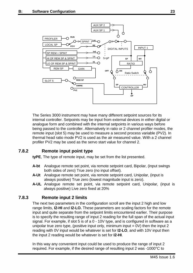
The Series 3000 instrument may have many different setpoint sources for itsinternal controller. Setpoints may be input from external devices in either digital oranalogue form and combined with the internal setpoints in various ways beforebeing passed to the controller. Alternatively in ratio or 2 channel profiler modes, theremote input (slot 5) may be used to measure a second process variable (PV2). Inthermal head ratio mode PV2 is used as the air measured value. With a 2 channelprofiler PV2 may be used as the servo start value for channel 2.
7.8.2 Remote input point typetyPE, The type of remote input, may be set from the list presented.
A-bt Analogue remote set point, via remote setpoint card, Bipolar, (input swingsboth sides of zero) True zero (no input offset).
A-Ut Analogue remote set point, via remote setpoint card, Unipolar, (input isalways positive) True zero (lowest magnitude input is zero).
A-UL Analogue remote set point, via remote setpoint card, Unipolar, (input isalways positive) Live zero fixed at 20%
7.8.3 Remote input 2 limitsThe next two parameters in the configuration scroll are the input 2 high and lowrange limits, I2-HI and I2-LO. These parameters are scaling factors for the remoteinput and quite separate from the setpoint limits encountered earlier. Their purposeis to specify the resulting range of input 2 reading for the full span of the actual inputsignal. For example, if slot 5 is of a 0 - 10V type, and is configured in software as aunipolar true zero type, (positive input only, minimum input = 0V) then the input 2reading with 0V input would be whatever is set for I2-LO, and with 10V input thenthe input 2 reading would be whatever is set for I2-HI.
In this way any convenient input could be used to produce the range of input 2required. For example, if the desired range of resulting input 2 was -1000°C to
PROFILER
LOCAL SP
SLOT 5
Loc
RE
Ind
Lo
Hi
RUN
R'DY
SWIRE
REM SP
REM SP
SP REM + SPINT
LO OF REM SP & SPINT
HI OF REM SP & SPINT
RATIO
S-tyP
DIGITAL INPUTS
AUX SP 1
AUX SP 2
SPINT
CONTROLLER
SP
SP
Ratio Switch
MV
OP
MV
INPUT 1
ONOFF
PV2
GAIN

24 Series 3000 Engineers Manual
M45 Issue 1.6
+1000°C, it is not necessary to use a bipolar input. Simply set I2-LO to -1000 andI2-HI to +1000, then with the 0 -10V unipolar true zero input, an input 2 reading of-1000 would result from a 0V input and a +1000 reading from a 10V input.
Please NoteWhen input 2 is used as the PV2 control variable then the same range constraintsapply as for input 1. See section 7.1.3.
7.8.4 Remote setpoint gain on/offWhen input 2 is used as an analog remote setpoint input, it is possible to apply afixed gain to the remote setpoint value if the value for I2-LO is zero. This feature isuseful when the user needs to allow the operator to change the scaling of theremote setpoint in the long scroll. The actual gain value is set in the long scroll SPgroup as the GAIN parameter. If this feature is not required then the GAIN switchshould be set to OFF.
7.9 Retransmission Group 'rEtr'
7.9.1 RetransmissionIf any slot is dedicated to rEtr, (retransmission) then the controller may beconfigured to retransmit one of a number of parameters as an analogue voltage.The retransmission range and bias are set in software. There may be up to tworetransmission outputs in slots 2 and 4 and hence there are two sets of parameters,one for each output.
7.9.2 Retransmission TypeSome versions of the Series 3000 are available with characterised PWM (pulsewidth modulated) retransmission outputs as well as the standard linear analoguetype. These instruments have the additional parameter tyPEX parameter which isused to select the retransmission type.
Lin Perform standard linear analogue retransmission
ChAr Perform characterised PWM retransmission. This is a digital logic signaldesigned to drive non-intelligent FGH controllers such as the Series 502and DRMC. The output PWM signal mimics the output from the series400 and 250A programmers.
7.9.3 Retransmission RangeWhen using characterised PWM retransmission it it necessary to specify thecharacterising range code using the parameter rnGEX. The characterisation rangecode should be entered using the same range numbering system as for input 1.However there is no need for the retransmission range to be the same as the maininput range.
7.9.4 Retransmission parameterPAr, the retransmission parameter dictates which of the parameters are to beretransmitted.

B: Software Configuration 25
M45 Issue 1.6
OFF no retransmissionPV1 Process variable 1, the value of input 1PV2 Process variable 2, the value of input 2SP1 set point 1, current set point value being usedSP2 set point 2, current set point value being usedAir the current air setpoint on a thermal head ratio system.OP The current output level in %. Note this value can be negative on a heat/cool
type controller.USEr The value to be retransmit is supplied by the user via the serial
communications parameter 'M'.
7.9.5 Retransmission limits for analog rtxThe next two parameters in the configuration scroll are the retransmission high andlow range limits, Hi X and Lo X (+9999 to -9999). These will be included in theconfiguration scroll as long as the retransmission parameter, PAr, is not set to OFF.The selected parameter is scaled between these limits before retransmission toprovide 100% output when the selected parameter has a value greater than orequal to HI X and 0% output when less than or equal to Lo X.
Note. The user may specify Lo X to be greater than Hi X. This has the affect ofinverting the retransmission output.
7.9.6 Retransmission limits for PWM rtxFor PWM retransmission, the Hi X and Lo X parameters specify the range of thecharacterised output. This is usually 0 to 2000 degrees for compatibility with FGHseries 502 and DRMC controllers.
7.9.7 Retransmission biasThe next configuration parameter is retransmission bias, bIAS. This may be used toprovide a live zero output. If, for instance, the retransmission output has beenarranged to provide a 0 to 20mA output over the range of values of interest, then ifthe retransmission bias is set to 20% the output will now be 4 to 20mA.
7.9.8 PWM Retransmission TrimWhen using PWM retransmission, it is possible to apply a span trim to the output byusing the parameter trinX. Since the PWM output is a digital signal, it is not possibleto calibrate it using the normal zero and span method in the CAL scroll group. ThetrinX is therefore used to adjust the span of the output slightly to ensure bettercalibration.
7.10 Serial communication Group 'ConS'
7.10.1 Digital serial communicationsAll Series 3000 instruments have the option of fitting digital serial communications. Ifthis feature is used then the following parameters should be set up to suit the deviceto which the instrument is connected.
bAUd select the baud rate required

26 Series 3000 Engineers Manual
M45 Issue 1.6
AddrS select the controller address required, between 0 and 99. Bear inmind if it is desired to address groups of instrumentssimultaneously by use of the wildcard address then the addressmust be selected accordingly. (see the Series 3000communications manual provided with the instrument).
Remember that with a P3000 the address set relates to thecontroller part of the instrument and the profile generator part ofthe instrument will have an address of the controller address+16.
7.10.2 Digital remote setpoint ON/OFF switchAll Series 3000 instruments may receive a remote setpoint value via the serialcommunications parameter ‘@’. This feature may be enabled or disabled using theCrSP scroll element.
OFF Digital remote setpoint is disabled.On Digital remote setpoint is enabled.
7.10.3 Digital setpoint retransmission (P3000 Only)It is possible to utilise the serial communications facility to transmit the setpoint toone or more remote controllers. This however precludes the use of the serialcommunications network with a host computer. Since the P3000 may have a 2channel profiler, it is possible to direct the two setpoints to two different controllergroups.
The parameter Sout1 is provided to direct the digital channel 1 setpoint to thecontroller group required for profile channel 1 operation. Similarly Sout2 is providedfor channel 2.
For each parameter Sout1 and Sout2 the user has the following options.
OFF Digital setpoint transmission is disabled.
1_ The setpoint is directed to instruments with addresses 10 to 19 inclusive.up to9_ The setpoint is directed to instruments with addresses 90 to 99 inclusive.
External instruments required to receive this digital setpoint should be set up withremote digital setpoints enabled.
NOTE.The digital setpoint retransmission feature will be disabled automatically under thefollowing conditions.
The serial communications (Slot 6) is switched on.
AND The comms remote setpoint feature is enabled (CrSP = On).
AND A digital input has been up as remote/local setpoint control (DinX=r-SP)
AND The digital input is made (Remote SP is requested).

B: Software Configuration 27
M45 Issue 1.6

28 Series 3000 Engineers Manual
M45 Issue 1.6
SECTION C - PROGRAMMING THE PROFILE GENERATOR
8.0 GeneralThe P3000 programmer creates a time/temperature profile on up to two channelsfrom a sequence of time and temperature (level) co-ordinates. the resultant profiletherefore consists of linear rates of change of setpoint with time. Each linear sectionof the profile is referred to as a segment.
The profiler runs each segment in turn until it encounters an END segment or itreaches the last available segment. At this point the profile may automatically berepeated using the repeats feature. On a two channel profiler, the two profiles aresynchronised at each segment boundary. The channel which completes its ramp ordwell first will wait at the end of the segment until the other channel has completedits operation.
During each segment the user may elect to specify a set of digital outputs (calledevents) and a set of applicable control terms (called terms sets). The profiler willautomatically select and use the appropriate set for each segment.
The setpoint profile may deviate from the actual programmed profile on certainoccasions namely profile start, mains supply interruptions and hold conditions.These three aspects are explained in detail below.
Although the Proteus can be employed to control a wide variety of variables, for thesake of simplicity these explanations will assume that the process variable beingcontrolled is temperature.
8.1 Start sequenceWhen the profile generator is in it's ready state (ie. a profile is not running and the'SEG' element of the short scroll shows 'rEAdy') then the controller obeys the localsetpoint (SPLOC for channel1 and SPL 2 for channel 2). When the start instructionis given a complex sequence of events occurs that results in the controller obeyingthe profile generator setpoint. The start sequence is:
1. Scroll through the short scroll until the 'SEG' element is displayed. Now use the star
and Auto/Man (PROG) button to select the number of the program to be started. 2. The profile may be started in one of three ways: Manually by pressing and holding
the star button and momentarily pressing the up (START) button, via serialcommunications by sending a ‘set start’ command to the profile generator or via oneof the instruments digital inputs when it is configured as a START or aSTART/HOLD function. See section 7.6.
3. The controller continues to obey the local setpoint until the delay start time has
elapsed 4. When the delay start time has elapsed the instrument advances to the first segment
of the profile

C: Profile Generator 29
M45 Issue 1.6
5. If the time of the first segment (tX-1) is zero then the profile step changesimmediately to the first segment's level (LX-1) and the controller henceforth obeysthe profile generator setpoint. The profile then advances and begins execution ofthe second segment.
6. If the time of the first segment (tX-1) is not zero then the instrument considers the
measured value. 7. If the measured value is within the nominal range of the instrument then the profile
jumps to equal the measured value and henceforth the controller obeys the profilegenerator setpoint. The profile then executes the first segment. The first segmentwill be a ramp that begins at the measured value and ends at segment 1 level (LX-1). The rate of the first segment will be as if segment 1 had started from a levelof zero.
8. If the measured value is outside the nominal range of the instrument then the profile
jumps to equal the local setpoint and henceforth the controller obeys the profilegenerator. Since the measured value is out of range, the profile generator goes intoa hold condition and the profile remains stationary. When the measured valuecomes into range the hold condition is freed and the profile executes the firstsegment. The first segment will be a ramp that begins at the local setpoint and endsat segment 1 level (LX-1). The rate of the first segment will be as if segment 1had started from a level of zero.
MV
SEG 1TX-1 TX-2 TX-3 TX-4
SEG 2 SEG 3 SEG 4
DELAYSTART
Normal profile start(Servo Start)
0
LX 3
LX 1,LX 21 L 2
SPLOC

30 Series 3000 Engineers Manual
M45 Issue 1.6
P3000 profile generators are equipped with a fast facility. This allows the profile, orpart of the profile to be executed rapidly. While the star button and right (FAST)buttons are pressed the profile will execute at about 20 times normal speed.
8.2 Supply interruptionIf the mains supply to the instrument is interrupted whilst a profile is being executedthen a complex sequence of events occurs that attempts to minimise thedisturbance to the process. The instruments behaviour after a supplyinterruption will result in an unexpectedly long total profile time. Uponrestoration of the supply the sequence is:
1. The instrument delays for approximately 10 seconds whilst other controllers etc.
recover after the mains failure 2. If the interrupted segment is a ramp and the measured value is within the nominal
range and a hold is in existence, then the profile is made equal to the measuredvalue, (Servo Start) and the ramp continues at the previous rate towards thesegments level.
3. If the interrupted segment is a ramp and the measured value is out of range then
the profile remains at the point it had reached before the interruption. Since themeasured value is out of range the profile generator goes into a hold condition andthe profile remains stationary. When the measured value comes within range theramp continues.
4. If the interrupted segment is a dwell and the measured value is within the nominal
range and a hold is in existence, then the profile is made equal to the measuredvalue (Servo Start). The profile generator then calculates the rate of the last rampperformed and then brings the profile back to the dwell level at that rate. If the lastramp happened to be a step change then the profile step changes. Once the dwelllevel is reached then the dwell continues from where it was interrupted.
MV
SPLOC
SEG 1TX-1 TX-2
SEG 2
DELAYSTART
SPAN
LX 1-
Overrange profile start

C: Profile Generator 31
M45 Issue 1.6
5. If the interrupted segment is a dwell and the measured value is out of range thenthe profile remains at the dwell level. Since the reading is out of range the profilegenerator goes into a hold condition; when the measured value comes back intorange the dwell continues from where it was interrupted.
6. If, on recovery after a mains failure no hold conditions exist, then it is assumed that
the mains failure was of very short duration and therefore the instrument does notservo start, but continues with the profile as if nothing had happened
8.3 Hold conditionAt certain times during the execution of a profile, the profile generator may go into ahold condition. A hold condition causes the normal progress of the profile to bemodified and the total duration of the profile will not be as expected. When theinstrument is in hold the lower display will flash to indicate this. Holds can originatefrom any of four sources:
• A hold can be caused manually from the instrument front panel. This is achieved by
holding the star button and pressing the left (HOLD) button. Press this pair ofbuttons again to release the hold.
POWER OFF10 HOURS
20°C/hr
300°C
200°C
400°C
Temp falls to 200°Cduring power failure
Ramp continuesfrom 200°C at20°C/hr
100°C
INTERRUPTION OF RUNNING RAMP
1 hour 2 hours
POWER OFF
30°C/hr
250°C
Temp falls to 150°Cduring power failure
SP returns todwell level at30°C/hour
INTERRUPTION OF A 3 HOUR DWELL
250
150°C

32 Series 3000 Engineers Manual
M45 Issue 1.6
• A communicating profile generator may have its running profile held via the serialcommunications link by means of a ‘set hold’ command This hold is freed bysending a 'set free’ command to the instrument.
• A hold may be generated via a contact closure on one of the instruments digital
inputs. In order for this to work, the appropriate digital input must be configured in 'EMode' as a Hold. A digital input could also be configured and used as a 'Start/Hold'.see section 7.6
• A hold will be generated by the profile generator if the difference between themeasured value and the control set point exceeds the hold band parameter set inthe programmer long scroll and the hold is active for an error in that direction(Above or Below) as set on the hold-type parameter in the programmer long scrolland the part of the profile currently executing (Ramp or Dwell) is also set on thehold-type parameter in the programmer scroll.
If a hold occurs during a ramp segment then the ramp will remain stationary for theduration of the hold. If a hold occurs during a dwell then the dwell time is extendedby an amount equal to the period of the hold.
IN HOLD IN HOLD
MV
+ HOLD
SP
- HOLD
Dwell timer suspended during hold. Note that 'Above', 'Below' and'Dwell' holds at least are set on in the hold-type parameter of theprogrammer long scroll.
Holds during a dwell
MV
+HOLD
SP
-HOLD
IN HOLD
Below andRamp holdsonly set inparameterHold-type inprogrammerlong scroll
Ramp is suspended whilst in hold
HOLD ON A RUNNING RAMP

C: Profile Generator 33
M45 Issue 1.6
8.4 Ending a profileA profile can be ended manually at any time during the profile or can beprogrammed to end at any segment of the profile. The profile will also end as amatter of course when segment 25 finishes. When the profile ends control reverts tothe controllers local set point and the profile generator becomes ready. The profileends by:
1. Holding the star button pressed and pressing the down (STOP) button. 2. Closure of a contact on one of the instruments digital inputs which has been
configured as a 'STOP'. See section 7.6. 3. Via the serial communications facility by sending a ‘set stop’ command to the
programmer. 4. Encountering an END instruction programmed into the profile. A segment is
programmed with an end instruction if the segments time is reduced down to andpast zero so that the lower display shows the mnemonic 'End'. The end instructiontells the programmer to see if the profile is to be repeated, and if so, if the requirednumber of repeats are done. If there are no repeats, or if they have all been donethen the profile ends.
8.5 Repeating the profileThe profile is always run once when the start instruction is given, but it can also beprogrammed to repeat itself up to 999 times by setting the 'repts' parameter in theprogrammer scroll to the required number of repeats. 0 means don't repeat at all.The profile will execute until either segment 25 has finished or an 'end' or 'go'instruction is encountered. At this point the profile returns to segment 1 and beginsagain
If the first segment is a step change then all repeats of segment 1 will be a stepchange; these steps will be from the last segments level to segment 1's level
If the first segment is a ramp then all repeats of segment 1 will be a ramp; theseramps will be from the last segments level to segment 1's level in segment 1's time.
While the profile is running the value of parameter 'repts' remains unchanged, butthe number of repeats remaining can be seen by viewing this parameter andpressing the star button. When the profile generator returns to the ready conditionthe number of repeats are restored.
8.6 Chaining profilesIf the segments available in one program are not enough for the profile desired thentwo or more programmes may be linked together to form a more complex profile. Asegment may be set to a 'GO' if the segment's time is reduced down to and pastzero to 'END' and then further down to 'Go 9', 'Go 8' etc. down to 'Go 0'.
A program segment is set to a Go in place of an End. When the executing programencounters a Go segment it checks to see if any repeats are left, and if so these areperformed between segment 1 and the Go segment. When all the repeats are

34 Series 3000 Engineers Manual
M45 Issue 1.6
complete (or if there are none) then program control is transferred to the start of theprogram number specified in the Go segment, this new program will have its ownunique number of repeats and may include its own Go segment to transfer controlto yet another program.
8.7 Delay start timerThe Proteus may be programmed to run a profile at some convenient time in thefuture. For example, if the time is now 4:30 PM and it is desired to run a processthat we know lasts 2 hours so that it just completes in time for the start of worktomorrow morning at 8:00, clearly we would like the profile to begin in 13 hours 30minutes time. To achieve this, simply select the program required to be run in theshort scroll, enter the programmer long scroll and set the first element (Delay) to13.30 and exit the long scroll. Now start the profile and we know that the Proteus willcontinue to control at the local set point until the profile generator takes over theprocess at 6 am and that the process will just complete in time for our 8 o'clock start

D: Hardware Configuration 35
M45 Issue 1.6
SECTION D - HARDWARE CONFIGURATION
9.0 GeneralThe S3000 controller/P3000 Programmer consists of a basic model which iscapable of being configured as many different types of instrument and expandedusing option cards and an options card carrier. Only the option cards required forperforming the desired task are fitted and waste is therefore minimised.
The S3000 Controller/P3000 Programmer comprises a 'basic' instrument, whichconsists of a circuit board assembly that slides into channels in a metal case andplugs into the terminal assembly at the rear. The board assembly, which has thedisplay unit fixed to the front of it, is then held in place with the two captive screwsvisible on the front panel.
9.1 Gaining access to the option boardsIn order to gain access to the option boards the instrument must be removed fromits case. This is achieved by unscrewing the two captive screws on the front panel,the instrument may then be drawn out from the case
In the basic model there is only one board attached to the display assembly, this isthe power supply and input board. This board plugs into the processor board via a15 way post and box. The board is held in place by two clips at the processor boardend. these clips should be gently eased apart if the power supply board is to beremoved
On the power supply board are two 'slots', slot 1 and slot 2. These are positions inwhich an options board may be fitted.
9.2 Fitting the options board carrierIf more options, or more sophisticated options such as retransmission or digitalcommunications are required then an options board carrier may be fitted. Thismakes available slots 3 to 5 which may be fitted with other options boards, and slot6, which may be fitted with the digital serial communications board.
The options board carrier plugs into the processor board in a similar manner to thepower supply board, however, a power supply link, supplied with the options carrierboard, must be fitted between the power supply board and the options carrier board.The link is connected at the power supply/input board, to the two pin post marked'AUX POWER'. The connectors are polarised and cannot be connected the wrongway around.
9.2.1 Transmitter power supplyThe options board carrier also provides a d.c. power supply capable of providing upto 25mA which may be used to power remote transmitters. This supply has an opencircuit output of approximately 30V. This power supply is always available in anexpanded instrument, (ie. with options board carrier fitted) and does not occupy anyof the options slots.

36 Series 3000 Engineers Manual
M45 Issue 1.6
9.3 Broken sensor drive selectionOn instruments fitted with power supply/input boards of revision 4 or later, there isprovision for the selection of sensor burn out direction. This is the direction in whichthe measured input signal will move if the thermocouple sensor should break. Onmost systems using reverse acting control this should be up scale. Systems usingforward acting control, or other special cases, may require down scale burnout.Linear or resistance thermometer inputs should have the burnout drive disabled.
The burnout direction is selected moving the jumper link as shown.
10.0 Options boardsThere are 7 different options boards which provide the additional facilities on theS3000 Controller. They are as follows;
10.1 Relay board PC1542This board provides one isolated form 'C' (changeover) contact. A CR snubbercircuit is fitted from each contact to common. The relay board option is used toprovide heat and cool time proportioning control outputs, alarm outputs andmotorised valve drive. The board is provided with two plastic spacers, so it is simplyclicked into place.
10.2 Remote setpoint board PC1543This board enables the S3000 controller to work from a remote analogue set point.The standard input to the board is ±10V, but if the push-on jumper link is fitted thenthe input range is changed to ±1V. Fitting both push-on jumper links enables 20mAinput. The input is isolated from all other supplies and decoupled to earth.
UPBURN
DOWNBURN
NOBURN
BURNSELECTOR
POWER SUPPLYISSUE 4
PC1543
AnalogueInputCard
1V Link 20mA Link
Make both links for 20mA input

D: Hardware Configuration 37
M45 Issue 1.6
Fitting this board requires one plastic spacer to be clicked into place and an M3screw and washer (supplied) to be fitted from the options board side.
10.3 Analogue output board PC1544This board enables the controller to generate an analogue output, 0 to 20mA or, ifthe two push-on links are fitted, 0 to 10v. The output is isolated from all othersupplies and decoupled to earth. Fitting this board requires one plastic spacer to beclicked into place and an M3 screw and washer (supplied) to be fitted from theoptions board or power supply board side.
10.4 Slide wire input board PC1545This board enables the instrument to control a motorised valve with slide wirefeedback. The board provides three wire connection to an unpowered slide wire asthe board provides its own supply. The input is isolated from all other supplies anddecoupled to earth. Fitting this board requires one plastic spacer to be clicked intoplace and an M3 screw and washer (supplied) to be fitted from the options boardside.
10.5 Digital serial communications board PC1541This board can only be fitted to slot 6 on the options board carrier, therefore, anyinstrument with serial comms must have an options board carrier to fit this board to.The serial comms board provides RS485, RS422 and RS232 type communicationsstandards, depending on which links have been made on the board and how theinstrument is wired. All these details are covered in the S3000/P3000Communications manual provided with this board. Fitting this board requires onlythe four plastic spacers to be clicked into place on slot 6. The digital communicationlines are isolated from the rest of the instrument and any other supplies.
10.6 Isolated logic drive and External event driver board PC1549This board provides a switching nominal 12V for driving Solid State Relays etc. andthe P3000 Programmers External Event Module. The 12v output is current limited toa nominal 20mA. The output is isolated from all other supplies and decoupled toearth. Fitting this board requires one plastic spacer to be clicked into place and anM3 screw and washer (supplied) to be fitted from the options board or power supplyboard side.
10.7 Remote program select input board PC1543AThis board may only be fitted to P3100 instruments and enables the user to selectremotely the profile number to be run by the instrument. The input is actually a lowresolution, high speed analogue input with a link selectable 1V or 10V span. For aboard set to the 10V range, the program number is selected at the rate of 0.4V perprogram allowing programs 0 to 24 to be selected remotely by a plc or other means.For example an input of 0V +/- 0.1V will select program 0, and an input of 4V +/-0.1V will select program 10.For front of panel selection the 'FGH remote program selector switch' card PC1559may be used to select programs 0 to 11.

38 Series 3000 Engineers Manual
M45 Issue 1.6
11.0 Slot availabilityWhen configuring the hardware of the instrument it is important to note that eachoption board can only go in certain slots, so the following table should be consultedto find an acceptable arrangement.
Power supply Options board carrierFunction Board Slot1 Slot2 Slot3 Slot4 Slot5Heat tp Relay/Logic drive *
Heat analogue Analogue out *Cool tp Relay/logic drive * *
Cool analogue Analogue out * *Raise valve Relay/logic drive *Lower Valve Relay/logic drive *
Alarm 1 Relay/logic drive * * *Alarm 2 Relay/logic drive * * *
Retransmit Analogue out * *Remote sp Remote sp *Slidewire Slidewire *
Internal event Relay/logic drive * * * * *Ext event drive Logic drive * * *Ext prog select Remote prog input *
Note. Slot 6 can only accept the serial comms board and the serial comms boardcan only fit in slot 6.
12.0 Part number codingThe part number consists of three parts, the instrument type, e.g. S3000, a two orthree digit code showing the sensor type, and two or five pairs of digits which givethe function of each of the expansion slots and what hardware is plugged into it.
Note that the instrument can be expanded or unexpanded. This means that if anexpanded instrument is ordered then an extra circuit board is built into it whichcontains expansion slots 3, 4, 5 and 6. (slot 6 is only used for the digital serialcommunications option. comms is, therefore, not available in an unexpandedinstrument.) If an unexpanded instrument is ordered, (S300x), then it is notnecessary to fill in slots 3 to 5.

D: Hardware Configuration 39
M45 Issue 1.6
Example 1. S3001-03-B4 G1 This describes an unexpanded controller, with aheat only analogue 0 - 20 mA control (in slot 1),and one alarm of relay type in slot 2. theinstrument will be delivered configured for a typeK thermocouple and work in degrees C. The 0 -20mA control output may be set by the user insoftware, to have a live zero, for example, 4 -20mA.
Example 2. P3213-15-E1 F1 G2 00 L8This describes an expanded 2 channel profilerwith EIA-485 serial communications, set up todrive a motorised valve, using a resistancethermometer sensor and working in tenths ofdegrees C. (-15-) with the option slots occupiedas follows.Slot 1 Raise motorised valve, relay outputSlot 2 Lower motorised valve, relay outputSlot 3 Alarm 1 with logic output (to drive an SSR)Slot 4 Empty. Available for future use as alarm 2,
retransmission or internal event.Slot 5 Unpowered slidewire input
-
S for controllerP for profile generator
1 EIA-485 comms2 EIA-422-A comms3 RS-232 type comms
Sensor type code and units. see table below.
0 for no control action1 for heat only2 for heat/cool action3 for motorised valve
0 Basic instrument (Single channel profiler)2 Two channel profiler
S 3
0 Unexpanded instrument
-Slot 1 Slot 2 Slot 3 Slot 4 Slot 5
Code for Functionand Hardware ofeach of the 5 generalpurpose expansionslots, eg. G 1 wouldresult in an alarm 1relay output beingfitted in that slot.
See the table belowfor code meanings.
Supply Voltage. H =22 to 52Vdc. Blank=88 to 265Vac.
4 Expanded instrument

40 Series 3000 Engineers Manual
M45 Issue 1.6
Two digit input type code00 Type S, (Pt-10% Rh / Pt) Degrees C01 Type R, (Pt-13% Rh / Pt) Degrees C02 Type J, (Fe / Cu-Ni) Degrees C03 Type K, (Ni-Cr / Ni-Al) Degrees C04 Type T, (Cu / Cu-Ni) Degrees C05 Type E, (Ni-Cr / Cu-Ni) Degrees C06 Type B, (Pt-30% Rh / Pt-6% Rh) Degrees C07 Type N, (Ni-Cr-Si / Ni-Si) Degrees C08* Type W, (W / W-26% Re) Degrees C09* Type W3, (W-3% Re / W-26% Re) Degrees C10* Type W5, (W-5% Re / W-26% Re) Degrees C11* Type NM, (Ni / Ni-18% Mo) Degrees C12 Type L, (Fe /Cu-Ni) Degrees C13 K10, Type K in 1/10 °C Degrees C14 T10, Type T in 1/10 °C Degrees C15 RT10, (PT100) in 1/10 °C Degrees C16 RT, (PT100) Degrees C
17 Type S, (Pt-10% Rh / Pt) Degrees F18 Type R, (Pt-13% Rh / Pt) Degrees F19 Type J, (Fe / Cu-Ni) Degrees F20 Type K, (Ni-Cr / Ni-Al) Degrees F21 Type T, (Cu / Cu-Ni) Degrees F22 Type E, (Ni-Cr / Cu-Ni) Degrees F23 Type B, (Pt-30% Rh / Pt-6% Rh) Degrees F24 Type N, (Ni-Cr-Si / Ni-Si) Degrees F
Slot Function
0 for not fittedA for heat t.p. outputB for heat analogue outputC for cool t.p. outputD for cool analogue outputE for mv raise outputF for mv lower outputG for alarm 1 outputH for alarm 2 outputI for retransmission outputK for remote setpoint inputL for mv slidewire inputM for external event driverN for internal eventR for Remote profile select input
Slot Hardware
0 for not fitted1 for a form C relay output2 for logic output (SSR driver)3 for 0 - 10v analogue output *4 for 0 - 20mA analogue *
for 4 - 20mA analogue *6 for +/- 1v analogue input *7 for +/- 10v analogue input *
8 for unpowered slidewire input
Note * user selectable level of live zero
Slot Function and Hardware codes.
5

D: Hardware Configuration 41
M45 Issue 1.6
25* Type W, (W / W-26% Re) Degrees F26* Type W3, (W-3% Re / W-26% Re) Degrees F27* Type W5, (W-5% Re / W-26% Re) Degrees F28* Type NM, (Ni / Ni-18% Mo) Degrees F29 Type L, (Fe /Cu-Ni) Degrees F30 K10, Type K in 1/10 °F Degrees F31 T10, Type T in 1/10 °F Degrees F32 RT10, (PT100) in 1/10 °F Degrees F33 RT, (PT100) Degrees F34 Linear, 0 to +90mV input35* Square Root, 0 to +90mV input
* These ranges are available on special request only and are not included onstandard instruments.
Note: All Type 34 (Linear) and 35 (Root) ranges except for 0 to +90mV input typesare supplied with appropriate external signal conditioning boards.

42 Series 3000 Engineers Manual
M45 Issue 1.6
SECTION E - CALIBRATION
13.0 GeneralThe following procedure enables the S3000/P3000 Controller to be calibrated in thefield if the reference equipment is available.
The reference equipment consists of a precision voltage and current source with anaccuracy of at least 10 times better than the controller.
If the controller will also be required to work on resistance thermometer ranges thena reference resistance source and appropriate range tables will also be required.
A voltage reference source will also be required for calibrating the remote set pointinput.
A digital volt meter (DVM) will be required if it is intended to calibrate analogueoutputs.
13.1 PreparationThe environment in which the controller is to be calibrated should be clean and dry,with a temperature between 15 and 25°C, humidity 0 to 80% Rh non-condensing.
The controller and any reference sources being used to calibrate it should havebeen in the calibration area and switched on for at least an hour prior to calibrationof the controller.
13.2 Main inputNote. To preserve the range changing ability of the instrument, the main inputshould be calibrated in linear mode with any external signal conditioning removed.ALL of the steps detailed below are necessary for perfect calibration.
13.2.1 Main input spanConnect the EZECAL or other precision voltage source to the controller in place ofthe thermocouple, using ordinary copper wires.
Place the controller into 'E' mode by removing the instrument from its sleeve,placing a shorting link across the two terminals on the processor board markedEMODE and replacing the instrument in its sleeve. (See section 6.1).Select the linear input range by setting the I-P parameter to 34. Set the input highlimit IPL-H to 4500 and the input low limit IPL-L to 0. Scroll on until the SPAN1parameter is displayed.
Set the EZECAL or precision voltage source to deliver +80.000mV and, using theup and down keys, adjust the input span until the display just changes from 3999 to4000.
When satisfied, press the star key and note down the displayed calibration constantfor future reference.

E: Calibration 43
M45 Issue 1.6
13.2.2 Resistance spanConnect a precision decade resistance box to the input terminals in the manner of aresistance thermometer. Use three wires of equal length and gauge.
Select the RT input range by setting the I-P parameter to 15. Scroll on until theSPANr parameter is displayed.
Set the decade resistance box to a value of 175.83 Ohms. Adjust the resistancespan using the up and down keys until the display just changes from 199.9 to 200.0.
When satisfied, press the star key and note down the displayed calibration constantfor future reference.
Return the input type I-P and the range limits SPL-H and SPL-L to the requiredvalues and return to normal working mode by removing the EMODE link.
13.2.3 Span adjustment for external signal conditioningIf the instrument is fitted with an external signal conditioning card, then the spanmay be adjusted by using the on board potentiometer. Connect up a precisionsignal source to the signal conditioning board and inject an appropriate signal(current or voltage) near the span of the instrument. Adjust the on board spanpotentiometer until the instrument display is correct.
13.3 Cold junction zeroMeasure the temperature of the instrument rear terminals with an accuratethermometer capable of being read to 0.1°C. Be sure to allow enough time for thereading to settle.
Scroll through the 'E' mode parameters until the CJC-Z parameter is displayed. Usethe up/down keys to set this to the measured temperature of the instrumentterminals.
When satisfied, press the star key and note down the displayed calibration constantfor future reference.
13.4 Remote set point input calibrationNOTE. The main input must be calibrated and connected before any attempt ismade to calibrate the remote setpoint input.
Input 2 can be configured as a remote set point input, or in the case of a valvepositioner unit, a motorised valve slidewire input. The following is the calibrationprocedure for a remote set point card.
Place the instrument in the 'E' mode configuration scroll, see section 6.1
Ensure that a remote set point board is fitted in slot 5, that in the 'E' modeconfiguration scroll SLOt5 is set to IP2 and r-SP (remote set point) and that rStyP(remote set point type) is set to A-bt (analogue, bipolar true zero). Connect the linkon the remote set point board to give it an input span of ±1V or remove it for ±10Vspan as required.

44 Series 3000 Engineers Manual
M45 Issue 1.6
Set rS-HI, which is the setpoint reading required with a maximum analogue remoteset point input, to 3000. Set rS-LO, which is the setpoint reading required with aminimum (most negative) analogue remote set point input, to -3000.
Set the current scroll element to ZErO2 and use a calibrated voltage source to inject-1V or -10V as appropriate to the span set, into the remote set point board inputterminals. Observe the input polarity which is terminal 26 with respect to terminal 25.
At this point, as before, there are two ways of calibrating this parameter, either holddown the star button and use the up/down keys to restore the input 2 zerocalibration factor, or without using the star button, use the up/down buttons to setthe display to -2999 and then carefully use repeated presses of the down buttonuntil the display just reads -3000. Record the input 2 zero calibration factor forfuture use
Set the scroll to SPAn2 and change the calibrated input voltage to +1V or +10V asappropriate. Again either restore the span2 calibration factor by holding in the starbutton and using the up/down buttons or just use the up/down buttons to set thedisplay to 2999, and then repeated presses of the up button until the display justreads 3000. Record the span2 calibration factor for future use.
Return the scroll to ZErO2, reset the input to -1V or -10V and check that the displayreads -3000. Set the input to 0V and check that the display reads 0. If so then all iswell.
Now that input 2 is calibrated you should return to rStYPE in the configuration scrolland set the remote set point type to the one required for operation. Adjust also thescaling factors rS-HI and rS-LO to whatever is required in use. Changing theseparameters will not affect the calibration of the instrument. However, changing theinput span between ±1V and ±10V will necessitate recalibration.
13.5 Slidewire input calibrationIf input 2 is being used as a slidewire input, then it may be calibrated in the followingmanner.
First of all ensure that the instrument is configured as a motorised valve positioner,(CTyP is VP), that a slidewire input board in fitted in slot 5 (SLt5 is IP2 and S-Fb,slidewire feedback) and that the motorised valve to be used is correctly connectedto the instrument rear terminals. (see installation manual ).
Invoke 'E' mode as described in section 6.1 and scroll on to the ZEr2 parameter inthe CAL group, this shows the currently measured valve position on the upperdisplay. While viewing this parameter the valve close output will be energised. Thiswill cause the valve to motor to its fully closed position. When the reading hassettled, press the star button to automatically calibrate the slidewire zero. Themessage donE will be displayed when this is complete. At this point the user mayuse the up and down buttons to make any fine adjustments required.
Scroll on to the next parameter SPn2, again the current measured valve position willbe displayed on the upper display. This time the valve open output will be energised

E: Calibration 45
M45 Issue 1.6
causing the valve to motor to its fully open position. When the reading has settled,press the star button to automatically calibrate the slidewire span. The messagedonE will be displayed when this is complete. As before the user may make anyfine adjustments required by using the up and down buttons.
13.6 Remote program selection input (P3000 only)This input is a low resolution, high speed analogue input which is used to selectremotely the program number to be used by the profiler, and therefore must becalibrated like any other analogue input. Calibration may be performed as follows:-
This procedure is given for a 10V input, the voltages required for a 1V input aregiven in brackets.
Connect a voltage signal source between terminals 19- and 20+. Activate Engineersmode and ensure that slot 3 is configured as a remote program select input bysetting parameter SLOt3 to E-Pr. Scroll on to the parameter IP3-Z and inject 0.0V from the signal source. Using the up and down keypads, adjust the displayedreading until it just changes from 1 to 0.Inject +10.0V (+1.0V) from the signal source and scroll on to the parameter IP3-S ,use the up and down keypads to adjust the reading until 1024 is displayed. Repeatthese two operations until both readings are correct.
Finally note down the zero and span constants for future reference. ( these valuesare obtained by holding down the star key whilst showing IP3-Z or IP3-S ).
13.7 Analogue output calibrationThere are 3 possible analogue outputs on the series 3000 instrument. These maybe fitted in slots 2, 3 or 4. Slots 2 and 4 are high resolution outputs and are capableof very fine calibration. Slot 3 however, is a low resolution output and can only becalibrated to 0.5%.This section will describe the calibration of an analogue output fitted in slot 2, but isequally applicable to slots 3 and 4.
Disconnect the wiring from the terminals of slot 2 and connect instead a digital voltmeter (a 4½ digit DVM is desirable). Select the DVM range appropriate to the typeof analogue output (20mA or 10V).
Enter EMODE as previously described and scroll on until the parameter OP2-Z isdisplayed. This is the output 2 zero adjustment. The instrument is now delivering 0Vor 0mA, adjust the zero setting by using the up and down keys until the DVM reads0V or 0mA as appropriate.
Scroll on one parameter until OP2-S is displayed. This is the output 2 spanadjustment. The instrument is now trying to deliver its full scale output of 20mA or10V. Adjust the span setting by using the up and down keys until the DVM reads20.000mA or 10.000V as appropriate. (remember slot 3 cannot be adjusted thisfinely).
Back scroll one parameter to OP2-Z and check that the zero reading is still correct,if not then repeat the zero and span adjustment until no further adjustment isnecessary.

46 Series 3000 Engineers Manual
M45 Issue 1.6
Finally note down the zero and span constants for future reference. (these valuesare obtained by holding down the star key whilst showing OP2-Z or OP2-S).
Remove the EMODE link to return the instrument into its normal operating mode.

Appendix 47
M45 Issue 1.6
Appendix A - Fault codesIn the rare event that one of the stored parameters is invalid, for example, afterreplacing the RAM or memory back-up battery, then when power is first applied tothe instrument a fault number will be displayed. When multiple faults occur thelowest numbered fault is generally shown first. Faults should be cleared one at atime until the fault indication disappears. This table shows which parameter must becorrected to restore operation.
Fault number Group Parameter at fault1..............................................IP1 I-P input type2..............................................IP1 ---- set point limits crossed over3..............................................IP1 ---- set point limits too far apart4..............................................IP1 SPL-H splimh out of limits5..............................................IP1 SPL-L spliml out of limits6..............................................IP1 CJC cjc type7..............................................IP1 IPL-H input 1 hi scalar8..............................................IP1 IPL-L input 1 lo scalar9..............................................IP1 ---- input 1 scalars crossed over10............................................IP1 ---- input 1 scalars too far apart11............................................Contr C-tyP controller type12............................................Contr C-Act forward/reverse switch13............................................Contr rAtIO ratio on/off switch14............................................Contr SEtS terms set type15............................................Contr tUnEr tuner type16............................................IO tPtyP slot 1 tp type17............................................IO tP on slot 1 tp minimum on time18............................................IO tPtyP slot 2 tp type19............................................IO tP on slot 2 tp minimum on time20............................................IO ZErO slot 2 live zero21............................................IO ZErO slot 3 live zero22............................................ProF CHAnS profiler channels23............................................ProF SErVb channel B servo type24............................................ProF SPb-H channel B hi sp limit25............................................ProF SPb-L channel B lo sp limit26............................................ProF Point channel B decimal point27............................................ProF PrOGS profiles available28............................................ProF SynC profiler sychronise switch29............................................ProF dELAy delay on/off switch30............................................ProF rEptS repeats on/off switch31............................................dinS din-1 digital input 1 type invalid32............................................dinS din-2 digital input 2 type invalid33............................................ALrS A1tyP alarm 1 type34............................................ALrS A1SEn alarm 1 sense35............................................ALrS A1HyS alarm 1 hysteresis36............................................ALrS ALr-1 alarm 1 level37............................................ALrS A2tyP alarm 2 type38............................................ALrS A2SEn alarm 2 sense39............................................ALrS A2HyS alarm 2 hysteresis40............................................ALrS Alr-2 alarm 2 level41............................................IP2 tyPE remote set point type42............................................IP2 I2-HI remote set point hi limit43............................................IP2 I2-LO remote set point lo limit44............................................IP2 ---- remote SP limits crossed45............................................rEtr tyPE1 retransmission 1 type

48 Series 3000 Engineers Manual
M45 Issue 1.6
46............................................rEtr PAr 1 retransmission 1 parameter47............................................rEtr HI 1 retransmission 1 high scalar48............................................rEtr LO 1 retransmission 1 low scalar49............................................rEtr bIAS1 retransmission 1 bias50............................................rEtr rnGE1 retransmission 1 char range51............................................rEtr tyPE2 retransmission 2 type52............................................rEtr PAr 2 retransmission 2 parameter53............................................rEtr HI 2 retransmission 2 high scalar54............................................rEtr LO 2 retransmission 2 low scalar55............................................rEtr bIAS2 retransmission 2 bias56............................................rEtr rnGE2 retransmission 2 char range57............................................ConS bAUd comms baud rate58............................................ConS AddrS comms address59............................................ConS Sout1 comms rtx 160............................................ConS Sout2 comms rtx 261............................................PASS PASS password62............................................SP SPLOC local setpoint63............................................SP S-tyP setpoint type64............................................SP rAtE setpoint slew rate limit65............................................SP SP1 auxiliary set point 166............................................SP SP2 auxiliary set point 267............................................Contr PrOP heat prop band68............................................Contr Iat heat integral time69............................................Contr dAt derivative time70............................................Contr aAPr derivative approach band71............................................Contr rEL relative cool power72............................................Contr rESEt manual reset value73............................................Contr dbAnd heat/cool dead band74............................................rAtIO rAtIO ratio75............................................rAtIO bAnd ratio band76............................................rAtIO Hi-OP ratio hi output limit77............................................rAtIO th-hi ratio hi thermal head limit78............................................rAtIO rEF ratio limit referece79............................................rAtIO th-lo ratio lo thermal head limit81............................................OP Act-t valve action time82............................................OP dbAnd valve dead band83............................................OP C PL cool power limit84............................................OP C CyC cool cycle time85............................................OP PL-h heat high power limit86............................................OP PL-l heat low power limit87............................................OP H CyC heat cycle time88............................................OP OP1 auxiliary output 189............................................OP OP2 auxiliary output 290............................................SP SP 2 local setpoint 291............................................FSAFE FSAFE on/off switch92............................................FSAFE FS Hi safety high limit93............................................FSAFE FS Lo safety low limit94............................................IP1 bIAS input 1 live zero bias%95............................................IP2 GAIN remote setpoint gain switch96............................................SP GAIN remote setpoint gain value