Series 300 API Filter Press
32
Series 300 API Filter Press ® Instruction Manual Part No. 207128 Rev. F
-
Upload
victor-manuel -
Category
Documents
-
view
57 -
download
4
Transcript of Series 300 API Filter Press

Series 300 API Filter Press® Instruction Manual
Part No. 207128 Rev. F

Copyright 2012 Fann Instrument Company
Houston, Texas USA All rights reserved. No part of this work covered by the copyright hereon may be reproduced or copied in any form or by any means -- graphic, electronic or mechanical without first receiving the written permission of Fann Instrument Company, Houston, Texas USA
Printed in USA
NOTE: Fann reserves the right to make improvements in design, construction and appearance of our products without prior notice. ®FANN is a registered trademark of Fann Instrument Company.
Fann Instrument Company PO Box 4350
Houston, Texas USA 77210 Telephone: 281- 871-4482 Toll Free: 800-347-0450
Fax: 281- 871-4358
TABLE OF CONTENTS

SECTION PAGE
1 Description ............................................................................................................................................................ 1
2 Safety Considerations .......................................................................................................................................... 2
3 Filter Press Pressure Sources ............................................................................................................................. 4
4 Standard Filter Press Test Procedures ............................................................................................................... 9
5 FREAD Filter Press Test Procedures ................................................................................................................ 11
6 Care of Equipment .............................................................................................................................................. 13
7 Parts List ............................................................................................................................................................. 15
FIGURES PAGE
1 CO2 Cartridge Holder Assembly .......................................................................................................................... 3
2 No. 207223 - Filter Press with Nitrogen Cylinder (Pressure Source) ................................................................. 4
3 No. 207290 - Dead-Weight Hydraulic Filter Press .............................................................................................. 6
4 No. 208594 - Dead Weight Hydraulic Assembly ................................................................................................. 6
5 No. 208647 - CO2 Pressure Assembly,Exploded View ...................................................................................... 7
6 No. 208652 - Pressure Regulator Assembly ....................................................................................................... 8
7 Filter Press and Cell Assembly, Exploded View ............................................................................................... 10
8 Filtration Reduction Evaluation Device-(FREAD) .............................................................................................. 12
9 No. 207127 - Filter Press, Standard Frame....................................................................................................... 14
10 No. 207174 - Filter Press, Standard Frame w/Regulator .................................................................................. 16
11 No. 207224 - Filter Press w/CO2 ....................................................................................................................... 17
12 No. 207503 - Filter press Wall Mount Frame w/CO2 ........................................................................................ 20
13 No. 207356 - Filter Press, Wall Mount in Case ................................................................................................. 21
14 No. 207673 - Filter Press Six-Cell with Manifold ............................................................................................... 23
15 No. 208648 - CO2 Pressure Assembly with Top Cap....................................................................................... 25

1
SECTION 1
DESCRIPTION
Filtration and wall-building properties of drilling fluids and cement slurries are determined by a filter press. The filtration rate is a measure of fluid loss measured in milliliters [1 milliliter (ml) = 1 cubic centimeter (cm
3)] under 100
pounds per square inch (psi) (690 kPa) of pressure through a special filter paper for 30 minutes. Wall-building characteristics are demonstrated by the thickness and consistency of the filter cake (the residue) deposited on the filter paper at the end of this period. The filter cake is measured to the closest 1/32" (0.8 mm).
The low pressure filter press assemblies described in this booklet consists of a filter cell mounted in a frame, a pressure source, a filtering medium, and a graduated cylinder for receiving and measuring the filtrate.
The filter cell, or drilling fluid cell, is constructed of rustproof anodized aluminum and chrome plated brass, or stainless steel.
Pressure sources deliver the required 100 ± 5 psi (690 ± 35 kPa) and may consist of compressed nitrogen or air in cylinders, CO2 gas cartridges, high pressure air or water systems, or a dead-weight hydraulic pressure assembly.
CAUTION
DUE TO THE HAZARD OF EXPLOSION, COMPRESSED OXYGEN SHOULD NOT BE USED AS A PRESSURE SOURCE.
The filtering medium normally is a filter paper that has been especially hardened for filtrate testing. The filtrate receiver is a 10 or 25 ml graduated cylinder.
NOTE: A filtration Reduction Evaluation Device (FREAD) is available for use in the Model 300 filter presses. This device adapts the filter press cell to hold a 1/4 inch (6.3 mm) porous ceramic filter which replaces the filter paper.

2
SECTION 2 SAFETY CONSIDERATIONS
Safe operation of Filter Presses requires that the laboratory technician or drilling fluids engineer be familiar with the proper operation and potential hazards associated with this equipment. Pressurizing the drilling fluid sample cell poses the potential hazards of the cell or associated pressurization equipment leaking and releasing sample or pressurizing fluid which could cause serious injury. Several precautions that should be observed are listed below:
1 Always use either Nitrogen, Carbon Dioxide, or compressed air. Never connect the Filter Press to Oxygen, natural gas, or any other non-recommended gas. If Nitrogen is used it must be supplied from an approved Nitrogen gas cylinder. Nitrogen Cylinders must be secured and meet all safely standards. Carbon Dioxide is normally supplied in small cartridges which contain about 900 psi (6206 kPa) pressure. They are primarily used for field operations. Do not allow these cartridges to be heated or exposed to fire. They can explode if overheated. If compressed air is used, its maximum pressure should not exceed 150 psi (1035 kPa).
2 Maintain pressure regulators in good condition. Never use oil on pressure regulators. Leaking
pressurization systems should be repaired or replaced. Gauges, fittings and hoses should be kept in good condition and leaks should be found and corrected. Periodically test the safety relief valves on the pressurization manifolds to verify they will relieve if excessive pressure should occur. Never plug or bypass these safety valves.
3 When pressurizing the Cell always make sure the regulator is closed (Tee screw backed all the way out,
counterclockwise), then open the supply pressure, then adjust the regulator. Do not attempt to pressurize higher than 100 psi. (694 kPa). Follow the procedure as outlined in Section 3-A and 3-B. When de pressurizing, shut off the supply pressure, bleed the system of pressure, then back out the regulator Tee screw following the procedures in Section 4, Step 7 or Section 5, Step 8.

3
Fig. 1 CO2 CARTRIDGE HOLDER ASSEMBLY

4
SECTION 3 FILTER PRESS PRESSURE SOURCES
A. CO2 CARTRIDGE PRESSURE SOURCE
Follow this procedure to pressurize the filter press with a CO2 cartridge pressure source (Refer to Fig. 1)
1 Remove the barrel from the CO2 pressuring assembly and insert a fresh CO2 cartridge.
2 After making sure the safety bleeder valve is closed, and the regulator adjusting screw is backed out to the closed position (maximum outward), turn the barrel loosely with the fingers until first contact with the puncturing pin is felt.
3 Advance the holder an additional 1/4 turn. The puncture pin, shown in Fig. 1, seals when the cartridge seats.
4 Screw the adjusting screw into the regulator to apply 100 ± 5 psi (690 kPa) pressure to the filter cell as
indicated by the test pressure gauge. Start 30-minute timing now.
CAUTION
WHEN USING SYSTEMS WITH CO2 CARTRIDGES AS A PRESSURE SOURCE, NO INLET PRESSURE GAUGE OR VALVE IS USED. USE CARE WHEN REPLACING SPENT CO2 CARTRIDGES. THERE COULD BE SOME PRESSURE LEFT IN THE CARTRIDGE. KEEP CO2 CARTRIDGES AWAY FROM EXTREME HEAT.
Fig. 2 - NO. 207223 FILTER PRESS WITH NITROGEN CYLINDER PRESSURE SOURCE

5
B. NITROGEN CYLINDER PRESSURE SOURCE
Follow this procedure to pressurize the filter press with a Nitrogen cylinder pressure source (Refer to the assembly in Fig.2):
1 With the regulator adjusting screw backed out to the closed position (maximum outward), slowly open the pressure valve on the cylinder. The inlet pressure gauge should show the cylinder pressure. Be sure this is greater than 100 psi, (690 kPa).
2 Be sure the hose between the cylinder regulator and the cell is all fittings are tight, and the safety-bleeder
valve is closed.
3 Screw the regulator adjusting screw into the regulator to apply 100 ± 5 psi (690 kPa) pressure to the filter cell, as indicated by the test-pressure gauge. Start 30-minute timing now.
CAUTION
ALWAYS SCREW THE REGULATOR ADJUSTING SCREW TO ITS MAXIMUM OUTWARD POSITION BEFORE OPENING THE RELEASE VALVE ON THE PRESSURE SOURCE. IF THE FULL PRESSURE OF THE PRESSURE SOURCE IS RELEASED TO AN OPEN REGULATOR, THE REGULATOR IS PUT UNDER A SEVERE STRAIN. IF THIS CAUSES THE REGULATOR TO FAIL, THE FULL TANK PRESSURE IS RELEASED TO THE FILTER PRESS AND IT MAY BE DAMAGED. AS AN ADDED PRECAUTION, A SAFETY BLEEDER VALVE THAT RELEASES AT APPROXIMATELY 170 PSI IS PLACED IN THE SYSTEM BETWEEN THE REGULATOR AND THE FILTER PRESS.
C. DEAD-WEIGHT-HYDRAULICS PRESSURE SOURCE
The Dead-Weight-Hydraulic Filter Press is a Series 300 Filter Press equipped with a Dead-Weight Hydraulic Assembly. The Dead Weight Hydraulic Assembly is shown in Fig. 4. Follow this procedure to pressurize the filter press with the deadweight-hydraulic pressure source:
1 Fill the water reservoir and cylinder of the dead-weight assembly to the top with clean fresh water.
2 Open the bleed-off valve and place the piston, with the weight attached, in the cylinder. Allow the piston to travel full stroke. Refill the reservoir with clean, fresh water and close the bleed-off valve.
3 Set the unit in place on the filter press frame and tighten the attaching set screws, if not previously
attached.
4 Connect the air hose from the dead-weight assembly to the top cap pressure inlet, if not previously attached.
5 Raise the weight to the top of its stroke and allow it to settle. In about two-thirds of the stroke, the delivery
pressure gauge will indicate 100 psi.
Lift the dead weight back to the top of the stroke. Start the timing of the test when the weight is released. One stroke of the piston will allow a maximum filtration loss of approximately 30 ml.

6
Fig. 3 - NO. 207290 DEAD-WEIGHT HYDRAULIC FILTER PRESS
Fig. 4 - NO. 208594 DEAD WEIGHT HYDRAULIC ASSEMBLY

7
D. EXTERNAL PRESSURE SOURCE
Almost any compressed air source, with a reliable pressure of more than 100 psi, (690 kPa) is suitable to pressurize the filter press. However, there must be a suitable regulator, on this line so that the pressure to the cell can be regulated. A regulator such as 208615 or 208652 is suitable. A shutoff valve and a hose should be installed between the regulator and the filter press cell. Refer to Figs. 5 and 6 and the following Note.
NOTE: The 208615 regulator is designed for maximum inlet pressures of 1000 psi, (6940 kPa.) and the 208652 regulator is designed for inlet pressures between 1000 psi (6940 kPa.) and 3000 psi (20820 kPa).
Fig. 5 - NO. 208647 CO2 PRESSURE ASSEMBLY,EXPLODED VIEW

8
Fig. 6 - NO. 208652 REGULATOR ASSEMBLY

9
SECTION 4 STANDARD FILTER PRESS TEST PROCEDURES
Follow the steps in this procedure to operate the filter press with a compressed gas or dead-weight hydraulic pressure source:
1. Assemble the clean, dry parts of the filter cell in the following order Refer to Fig. 7:
a. base cap b. rubber gasket c. screen d. a sheet of filter paper e. rubber gasket f. filter cell
2. Secure the cell to the base cap by rotating it clockwise. 3. Fill the cell with the test sample to within approximately 1/4" (6mm) of the top. (Filling the cell to this level
lessens the volume of pressurizing gas required from the pressure source.) 4. Set the filter press cell assembly in place within the frame. 5. Check the top cap to make sure the rubber gasket is in place. Place the top cap, already connected to the
pressure source, onto the filter cell and secure the cell in place with the T-screw. 6. Place a dry graduated cylinder under the filtrate tube, either on the support or in the clip. 7. Depending upon the pressure source being used, apply pressure to the cell following the appropriate
pressure source procedure as outlined in Section 3. 8. At the end of 30 minutes (or 7-1/2 minutes - Refer to Note below), close the pressure source valve and
back off the regulator, open the safety-bleeder valve. This releases the pressure on the entire system. 9. Measure the volume of filtrate collected in the graduated cylinder and record the filtrate loss in milliliters as
the API (30 minute) filtrate loss of the drilling fluid, or milliliters x 2 for the 7-1/2 minute test.
NOTE: The amount of filtrate collected after 7-1/2 minutes can be noted and, when this amount is multiplied by two,
it will give a rough estimate of the amount that will be collected in 30 minutes. The estimated valve is usually one or more milliliters short of the actual valve and this estimation procedure should not be attempted on drilling fluids having a filtrate loss of less than 5 ml in the 7-1/2 minute period.
10. Loosen the T-screw, remove the cell top, and then remove the cell from the frame. 11. Discard the drilling fluid. 12. Disassemble the filter cell and carefully remove the filter cake and filter paper from the base cap. 13. With a gentle steam of water (or, in the case of oil drilling fluids, with clean base oil), carefully wash excess
drilling fluid from the cake. 14. Measure and record the thickness of the filter cake to the nearest 1/32" (0.8 mm). 15. If desired, record properties of the filter cake such as texture, hardness, flexibility, etc.

10
Fig. 7 - FILTER PRESS AND CELL ASSEMBLY, \ EXPLODED VIEW

11
SECTION 5 FREAD FILTER PRESS TEST PROCEDURES
Follow this modified procedure if the FREAD ceramic disc adapter is to be used. Either compressed gas or the dead-weight-hydraulic unit can be used.
1. Assemble the Filtration Reduction Evaluation Device as follows, Refer to Fig. 8:
a. Assemble the selected porosity ceramic filter disc into the Body Adapter (1). b. Assemble "O" ring seal (5) into the Body Adapter. c. Install Ring Seal (2) into Body Adapter fitting it over the "O" ring. d. Screw the Seal Nut (3) onto the Body Adapter (1) and tighten hand tight. e. Install "O" Ring (4) on the outside bottom of the Body Adapter.
2. Assemble the dry parts of the filter cell in the following order. Refer to Fig. 7 and Fig. 8 omitting filter paper
and screen from Fig. 7.
a. base cap b. rubber gasket c. FREAD assembly. Refer to Procedure 1 above. d. rubber gasket e. filter cell Secure the cell to the base cap by rotating it clockwise.
3. Fill the cell with the test sample to within approximately 1/4" (6mm) of the top. (Filling the cell to this level
lessens the pressure volume required from the pressure source.)
4 Set the filter press cell assembly in place within the frame.
5 Check the top cap to make sure the rubber gasket is in place. Place the top cap, already connected to the pressure source, onto the filter cell and secure the cell in place with the T-screw.
6 Place a dry graduated cylinder under the filtrate tube, either on the support or in the clip.
7 Depending upon the pressure source being used, apply pressure to the cell following the appropriate
pressure source procedure as outlined in Section 3.
8 At the end of 30 minutes close the pressure source valve and back off the regulator, open the safety-bleeder valve. This releases the pressure on the entire system.
9 Measure the volume of filtrate collected in the graduated cylinder and record the filtrate loss in milliliters as
the 30 minute filtrate loss of the drilling fluid using the FREAD adapter and the micron size of the filter used for the test.
10 Loosen the T-screw, remove the cell top, and then remove the cell from the frame.
11 Discard the drilling fluid.
12 Disassemble the filter cell and carefully remove the FREAD assembly with the cake.
13 With a gentle steam of water (or, in the case of oil drilling fluids, with diesel oil), carefully wash excess
drilling fluid from the cake.
14 Measure and record the thickness of the filter cake to the nearest 1/32" (0.8 mm) and note that this test used the FREAD.

12
Fig. 8 – NO. 208582 FILTRATION REDUCTION EVALUATION DEVICE (FREAD)

13
SECTION 6 CARE OF EQUIPMENT
A. Cleaning
After each use, the filter press cell should be disassembled and cleaned of all drilling fluid by washing and thoroughly rinsing. Wipe off the rest of the filter press, and dry all parts completely. Replace the filter paper on the screen, and assembly the end cap onto the cell. Loosely reassemble the cell onto the frame for storage.
B. Pressure Regulator Maintenance and Repair
Most regulator troubles are caused by leaking fittings or faulty pins and seats. Rarely does a diaphragm rupture. If regulator will not hold pressure, check the fittings which are screwed into it. This is done by applying pressure to the system and looking for escaping gas in the form of bubbles. There are two methods of doing this. One method is to apply soap suds to the fitting areas, the other is to carefully immerse all but the pressure gauge in a container of water. If leaks are apparent, disassemble and apply tape thread sealant to the threads.
CAUTION
DO NOT USE OIL BASED THREAD DOPE OR OIL WHEN ASSEMBLING ANY REGULATOR.
Replacing the seat and pin.
If regulator connections do not leak, the seat and pin probably need replacement. Use the following procedure. Refer to items on Fig. 5 and 6.
1 Using a wrench on the hex of the spring case, unscrew the spring case. All parts down to and including the diaphragm will remain in the spring case.
2 Remove the thrust plate.
3 Unscrew the retainer and remove the seat with the pin.
4 Clean and inspect the regulator for evidence of dirt or drilling fluid in the regulator body. An outlet filter
(208626) is available to prevent this problem. 5 Replace the pin and seat.
6 Re-assemble the regulator.
C. Dead Weight Hydraulic Unit Maintenance
Always protect the mirror finish of the stainless steel piston, especially when removing it. Clean the fine mesh screen on the bottom of the water reservoir. If the piston moves sluggishly during a test, remove the piston and O-ring from the cylinder. Clean the O-ring groove in the cylinder. Examine the O-ring carefully for torn or rough places, and, if the surface is damaged, replace it with a new O-ring. Before replacing the O-ring and the piston, apply a light film of high-grade, water-repellent grease. In subfreezing weather, the water in the dead-weight assembly can be replaced by an anti-freeze solution such as propylene glycol and water; this does not adversely affect the operation of the unit.

14
Fig. 9 - NO. 207127 FILTER PRESS, STANDARD FRAME

15
SECTION 7
PARTS LIST
A. STANDARD FILTER PRESS ASSEMBLIES
1. 207127 Filter Press, Standard Frame (Refer to Fig. 9)
PART NO. DESCRIPTION
207128 Instruction Manual
207444 Pin for Insert
207999 Base Cap and Filtrate Tube
208059 Air Hose Adapter, 1/4" NPT x 1/4"
208062 Top Cap
208079 Cell Cylinder
208126 Frame
208255 Neoprene Gasket, (6 each)
208283 Support Rod
208310 Screen, Monel metal, 60-mesh
208349 Thumb Screw
208424 T-screw, stainless steel
208459 Graduated Cylinder Support
208626 Felt Filters
209389 Threaded insert
2. 207173 Filter Press Assembly
PART NO. DESCRIPTION
207127 Standard Filter Press
207929 Air Hose, 3 ft.
205868 Graduated Cylinder, 25 ml.
206051 Filter Paper, (100/box)

16
Fig. 10 - NO. 207174 FILTER PRESS, STANDARD FRAME, W/ REGULATOR
3. 207174 Filter Press (Refer to Fig. 11)
PART NO. DESCRIPTION
207127 Standard Filter Press
207929 Air Hose, 3 ft.
208602 Gauge, 200 psi, (1380 kPa), 1/8" NPT
208615 Regulator
208653 Safety-Bleeder Valve 170 psi (1100 kPa)
205868 Graduated Cylinder, 25 ml.
206051 Filter Paper, (100/box)

17
4. 207223 Filter Press, Nitrogen (Refer to Fig. 2)
PART NO. DESCRIPTION
207127 Standard Filter Press Assembly
207929 Air Hose, 3 ft.
208649 Air Cylinder, Nitrogen
208652 Regulator Assembly
208653 Safety-Bleeder Valve 170 psi (1100 kPa)
205868 Graduated Cylinder, 25 ml.
206051 Filter Paper, (100/box)
5. 207224 Filter Press, CO2 (Refer to Fig.11)
PART NO. DESCRIPTION
207127 Standard Filter Press
208647 CO2 Pressuring Assembly
205868 Graduated Cylinder, 25 ml
206051 Filter Paper, (100/box)
Fig. 11 - NO. 207224 FILTER PRESS, STANDARD FRAME,
W/ CO2 PRESSURE SOURCE

18
6. 207290 Dead-Weight Hydraulic Filter Press (Refer to Fig. 3)
PART NO. DESCRIPTION
207127 Standard Filter Press
208594 Dead-Weight Hydraulic Assembly
205868 Graduated Cylinder, 25 ml
206051 Filter Paper, (100/box)
7. 208594 Dead-Weight Hydraulic Assembly (Refer to Fig. 4)
PART NO. DESCRIPTION
207889 Hex Wrench, 1/8"
208759 Needle Valve, 1/8" NPT
208595 Reservoir
208596 Elbow, 1/8"
208597 Base w/Cylinder
208598 Weight
208599 Check Valve (2)
208600 Tee, 1/8"
208601 Hex Nipple, 1/8" x 1/8"
208602 Gauge, 200 psi, 1/8" NPT
208603 Adapter, 1/8"
208604 Air Hose w/connectors, 12"
208605 Piston
205653 O-Ring for Dead-Weight Piston

19
B. WALL MOUNT FILTER PRESS ASSEMBLIES
1. 207391 Filter Press, Wall Mount
PART NO. DESCRIPTION
207128 Instruction Manual
207444 Pin for Insert
207999 Base Cap and Filtrate Tube
208059 Air Hose Adapter, 1/4" NPT x 1/4"
208062 Top Cap
208079 Cell Cylinder
208255 Neoprene Gasket, (6 each)
208310 Screen, Monel metal, 60-mesh
208424 T-screw, stainless steel
208463 Clip for Graduate
208626 Felt Filters
209387 Frame, Wall Mount
209389 Threaded insert
209394 Frog Bracket
209395 Wall Bracket

20
2. 207503 Filter Press Wall Mount, w/C02 Pressure Assembly (Refer to Fig. 12)
PART NO. DESCRIPTION
207391 Filter Press, Wall Mount
208608 CO2 Cartridges (10/Box)
208647 CO2 Pressuring Assembly
205868 Cylinder, Graduated 25 ml
206051 Filter Paper (100/Box)
Fig. 12 FILTER PRESS, WALL MOUNT FRAME, W/ CO2 PRESSURE SOURCE
3. 207356 Filter Press CO2 Stainless Steel Case
(Refer to Fig. 13)
PART NO. DESCRIPTION
207391 Filter Press, Wall Mount
208608 CO2 Cartridges (10/Box)
208647 CO2 Pressuring Assembly
209184 Carrying Case, Stainless Steel
205868 Cylinder, Graduated, 25 ml
205869 Cylinder, Graduated, 10 ml
206035 Timer, Interval, 30 minute
206051 Filter Paper (100/Box)

21
FIG.13 207356 FILTER PRESS, WITH STAINLESS STEEL CASE

22
C. MULTIPLE CELL FILTER PRESS ASSEMBLIES
1. 207785 - Four Unit Filter Press, with manifold
PART NO. DESCRIPTION
207444 Pin for Insert
207786 Frame, Filter Press, Four Cell
207787 Manifold, Filter Press, Four Cell
207790 Preparation Tray, Filter Press Four Cell
207999 Base Cap and Filtrate Tube
208059 Air Hose Adapter, 1/4" NPT x 1/4"
208062 Top Cap
208079 Cell Cylinder
208255 Neoprene Gasket, (6 each per cell)
208283 Support Rod
208310 Screen, Monel metal, 60-mesh
208349 Thumb Screw
208424 T-screw, stainless steel
208459 Graduated Cylinder Support
208604 Air Hose w/connectors, 12"
208626 Felt Filters
208653 Safety-Bleeder Valve, 170 psi(1100 kPa)
208655 Needle Valve, 1/4" NPT
209389 Threaded insert
205587 Coupling 1/4 NPT
205589 Plug, Pipe 1/4 NPT
205868 Cylinder, Graduated, 25-ml
206051 Filter Paper (100/Box)
23
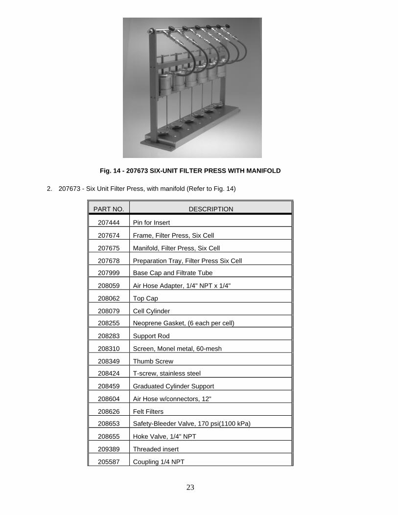
Fig. 14 - 207673 SIX-UNIT FILTER PRESS WITH MANIFOLD
2. 207673 - Six Unit Filter Press, with manifold (Refer to Fig. 14)
PART NO. DESCRIPTION
207444 Pin for Insert
207674 Frame, Filter Press, Six Cell
207675 Manifold, Filter Press, Six Cell
207678 Preparation Tray, Filter Press Six Cell
207999 Base Cap and Filtrate Tube
208059 Air Hose Adapter, 1/4" NPT x 1/4"
208062 Top Cap
208079 Cell Cylinder
208255 Neoprene Gasket, (6 each per cell)
208283 Support Rod
208310 Screen, Monel metal, 60-mesh
208349 Thumb Screw
208424 T-screw, stainless steel
208459 Graduated Cylinder Support
208604 Air Hose w/connectors, 12"
208626 Felt Filters
208653 Safety-Bleeder Valve, 170 psi(1100 kPa)
208655 Hoke Valve, 1/4" NPT
209389 Threaded insert
205587 Coupling 1/4 NPT

24
205589 Plug, Pipe 1/4 NPT
205868 Cylinder, Graduated, 25 ml
206051 Filter Paper (100/Box)
D. FILTRATION REDUCTION EVALUATION DEVICES
1. Filtration Reduction Evaluation Device Parts (Refer to Fig. 8)
PART NO. DESCRIPTION
206613 O-Ring 2-5/16 x 2-1/2 Viton
208583 Body Adapter for FREAD
208584 Ring, Seal for FREAD
208585 Nut, Seal for FREAD
205653 O-Ring 1/2 x 3/32
2. Filtration Reduction Evaluation Device Filters (Refer to Fig. 8)
PART NO. DESCRIPTION
210537 Filter 5 Micron
210538 Filter 10 Micron
210539 Filter 20 Micron
210540 Filter 35 Micron
210541 Filter 60 Micron
210542 Filter 90 Micron
210543 Filter 150 Micron
210544 Filter 190 Micron

25
E. CO2 PRESSURING EQUIPMENT
1 208647 CO2 Pressuring Assembly (Refer to Fig. 5)
PART NO. DESCRIPTION
208602 Gauge, 200 psi, 1-1/2" dia., 1/8 NPT
208608 CO2 Cartridges (10/box)
208612 Barrel for CO2 Cartridge
208614 Adapting Head with Puncture Pin
208615 Regulator
208653 Safety-Bleeder Valve, 170 psi
2 208648 CO2 Assembly w/Top Cap (Refer to Fig. 15)
PART NO. DESCRIPTION
208647 CO2 Pressuring Assembly
208062 Top Cap
Fig. 15 - 208648 CO2 ASSEMBLY WITH TOP CAP

26
3. Accessories For CO2 Assembly
PART NO. DESCRIPTION
208613 Adapter (for external pressure supply)
205608 Gauge, 200 psi, 1-1/2" dia., 1/8 NPT back conn.
4. 208615 Pressure Regulator, CO2 (Refer to Fig. 5)
PART NO. DESCRIPTION
208616 Seat
208617 Diaphragm
208618 Adjusting Screw, Spring Case
208619 Thrust Plate
208622 Spring Button
208623 Adjusting Spring
208624 Diaphragm Plate
208625 Slip Ring
208626 Output Filter
208628 Screens (2) 208643 Regulator Repair Kit consisting of:
Retainer Pin O-Ring Seat Seat Holder Spring Spring Guide

27
F. NITROGEN PRESSURING SYSTEMS
1. 208652 Regulator, Nitrogen, with Gauges, (Refer to Fig. 6)
PART NO. DESCRIPTION
208644 Adjusting Screw
208645 Spring Housing Cap w/Bushing
208641 Spring Button
208640 Adjusting Spring
208639 Slip Ring
208630 Diaphragm Nut
208631 Diaphragm Plate
208632 Diaphragm
208629 Centralizer
208633 Nozzle
208635 Gasket
208634 Seat Assembly
208638 Valve Spring
208637 Gland
208636 Bushing Regulator – Friction Washer
209467 Gauge, 3000 psi
208651 Gauge, 200 psi
208059 Outlet Connection
209472 Gland Nut, Left Hand
209473 Gland, Long (Inlet Connection)
203950 Gland Nut Right Hand

28
2. Nitrogen Supply System
PART NO. DESCRIPTION
208649 Cylinder, Nitrogen, (4" Dia. Size D)
208652 Regulator, Nitrogen, w/Gauges (Fig. 6)
208653 Safety Bleeder Valve, 170 psi (1180 kPa)
208655 Needle Valve, Male 1/4 NPT
208759 Needle Valve, Male 1/8 NPT
207929 Air Hose, 3 Ft., w/Connectors
207973 Air Hose, 6 Ft., w/Connectors
208613 Adapter, CO2 to Air Hose
209390 Speed Coupler or Air Hose
209393 Speed Connector for Coupler
G. FILTER PRESS ACCESSORIES
PART NO. DESCRIPTION
207129 Filter Press, with Stainless Steel Cell No. G3004
208080 Cell Gasket, Teflon
208122 Cell Body, Plexi-Glass
208311 Screen, Stainless, cement tests, 28 x 500 mesh
208312 Screen, Stainless, cement tests, 60 x 325 mesh
208463 Clip, with Bracket
208604 Air Hose 12"
209387 Frame, Wall Mount
209394 Frame Bracket
209395 Wall Bracket
205868 Cylinder, Graduated, 25 ml
205869 Cylinder, Graduated, 10 ml
206035 Timer, Interval, 30 minute

29
Warranty
Fann Instrument Company warrants its products to be free from defects in material and workmanship for a period of 12 months from the time of shipment. If repair or adjustment is necessary, and has not been the result of abuse or misuse within the 12-month period, please return, freight prepaid, and correction of the defect will be made without charge.
Out of warranty products will be repaired for a nominal charge.
Please refer to the accompanying warranty statement enclosed with the product
Return of Items
For your protection, items being returned must be carefully packed to prevent damage in shipment and insured against possible damage or loss. Fann will not be responsible for damage resulting from careless or insufficient packing.
Before returning items for any reason, authorization must be obtained from Fann Instrument Company. When applying for authorization, please include information regarding the reason the items are to be returned.
Our correspondence address is:
Fann Instrument Company P.O. Box 4350 Houston, Texas USA 77210
Telephone: 281-871-4482 Toll Free: 800-347-0450 FAX: 281-871-4446
Email: [email protected]
Our shipping address is:
Fann Instrument Company 15112 Morales Road, Gate 7 Houston, Texas 77032 USA