SERIES 170 LUBRICATION SYSTEM - Lincoln Orsco 170 Manual-0105.pdf6 Spare Parts ... Controls (refer...
15
ORSCO Lubrication Systems SERIES 170 LUBRICATION SYSTEM Table of Contents Page Page Installation Instructions ……………………………………….. 2 Series 170 System Model Code ………………………………. 7 Installation: Filter-Reg./Pressure switch assembly……… 3 Series 170 Description…………………………………………. 8 Reservoir…………………………………………………………. 4 Troubleshooting…………………………………………………. 9-10 VS Assembly…………………………………………………….. 5 Technical Data…………………………………………………… 11 Tubing Connections……………………………………………. 6 Spare Parts………………………………………………………. 12 Bleeding/Priming System…………………………………….. 6 Injector Description/Operation……………………………….. 13 Fill Lubricant Lines…………………………………………….. 6 VS Assembly Breakdown………..…………………………….. 14 50650 Corporate Drive, Shelby Township, MI 48315 (586)997-0300 phone -- (586)997-2072 fax www.lincolnindustrial.com [email protected]
Transcript of SERIES 170 LUBRICATION SYSTEM - Lincoln Orsco 170 Manual-0105.pdf6 Spare Parts ... Controls (refer...

ORSCO Lubrication Systems
SERIES 170 LUBRICATION SYSTEM
Table of Contents Page Page
Installation Instructions ……………………………………….. 2 Series 170 System Model Code ………………………………. 7 Installation: Filter-Reg./Pressure switch assembly……… 3 Series 170 Description…………………………………………. 8 Reservoir…………………………………………………………. 4 Troubleshooting…………………………………………………. 9-10 VS Assembly…………………………………………………….. 5 Technical Data…………………………………………………… 11 Tubing Connections……………………………………………. 6 Spare Parts………………………………………………………. 12 Bleeding/Priming System…………………………………….. 6 Injector Description/Operation……………………………….. 13 Fill Lubricant Lines…………………………………………….. 6 VS Assembly Breakdown………..…………………………….. 14
50650 Corporate Drive, Shelby Township, MI 48315 (586)997-0300 phone -- (586)997-2072 fax
www.lincolnindustrial.com [email protected]
ORSCO Lubrication Systems
Preventive Maintenance The danger in using automatic lubrication systems is Complacency! Pumps and injectors require priming at the time of commissioning. If the lubricant is depleted, then the pump/injector loses its’ prime. When the reservoir is later re-filled without being re-primed, it will appear as if the system is working … until someone notices that the fluid level has not changed!
W ARN ING!
This could result in serious damage to the equipment. Installation
• System must be mounted with the reservoir upright. • Install a protective and lockout device for isolating and disconnecting the Series 170 System.
Before beginning the installation work, disconnect the electrical supply. • The 24 VDC systems will require that the customer provide a remote disconnect switch within
line of sight and within 20 feet of the Series 170 electrical enclosure. • The 120 VAC systems will require that the customer provide a remote disconnect switch within
line of sight and within 20 feet of the Series 170 electrical enclosure. Failure to observe the safety instructions, e.g. touching electrically charged parts when the system is opened, may be life threatening! Installation Instructions • Mount Series 170 with 3/8-24 bolts according to template shown in Fig.1. • Allow adequate space for reservoir filling and routine maintenance.
Fig. 1: Series 170 Mounting pattern
20.75"
25.75"
Form 402999-Rev. 7 2 01-07-05
ORSCO Lubrication Systems
The Series 170 lubrication system can be divided into 4 major components: 1. Filter-Regulator/Pressure switch assembly 2. Reservoir assembly 3. VS assembly 4. Controls (refer to attached Controls Manual and system prints).
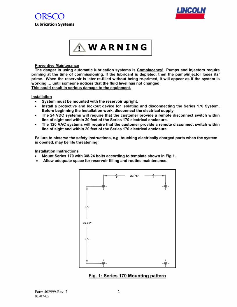
1. Filter-Regulator/Pressure switch assembly (Ref. Fig. 2): For supply air filtration, regulation and protection, the Series 170 provides as a standard a filter-regulator/pressure switch assembly. a. Filter (1): (5-micron element, auto-drain, and polycarbonate bowl). - Size supply source based on 1 SCFM per nozzle. - Connect supply source to 1/4” NPT filter inlet port. ** Quick disconnects are not recommended for this connection. **
b. Regulator (2): Relieving, 0-160 psig gauge (3) (Factory preset at 70 psig.) c. Pressure switch: (4), Provides verification of air supply. (Switch is preset from factory at
50 PSIG).
(1)
(3)
(2)(4)
Fig. 2: Filter-Regulator/Pressure switch assembly
Form 402999-Rev. 7 3 01-07-05

ORSCO Lubrication Systems 2. Reservoir assembly: There are two reservoir assemblies available for the system. All reservoirs
have a low level switch (3) and 100-mesh strainer (4) as standard. a. Manual fill (Ref. Fig. 3): - Remove fill plug (9) from reservoir top plate. - Fill reservoir and replace fill plug.
b. Central fill (Ref. Fig. 4): for remote filling of reservoir from a centralized tank. 1. Pressure feed
- Adjust regulator on pressurized central fill assembly (Ref. Fig. 4), to the closed position. Pull down on adjustment handle (5), to unlock, rotate handle counter-clockwise until closed.
- Connect ½” steel tubing from outlet side (6), of pressurized central fill assembly to the ½” steel tube fitting (7) supplied on the bottom plate of reservoir.
- Connect feed line to inlet side of pressurized central fill assembly. - Open drain cock (8) on reservoir top plate for initial filling. - Adjust regulator to 3 PSIG maximum. - Monitor fill process and close drain cock when reservoir is ¾ full.
2. Manual fill (Ref. Fig. 4)
- Open drain cock (8) and adjust regulator to 0 PSIG. - Remove fill plug (9) from reservoir top plate. - Fill reservoir, close drain cock and replace fill plug.
Fig. 3: Reservoir – Manual Fill Fig. 4: Reservoir –Pressurized Central Fill
MANUAL FILL CENTRAL FILL
(9)
(3)(4)
(8)(9)
(5) (6) (7)
Form 402999-Rev. 7 4 01-07-05

ORSCO Lubrication Systems
3. VS Assembly (Ref. Fig. 5): This is the core of the Series 170 lubrication system. The manifolded VS Assembly is a self-contained modular unit that incorporates valves to control the injector air supply as well as regulated air supply for the nozzle. The VS assembly can accommodate a maximum of 8 injectors per assembly.
a. Injector solenoid valve: (1) This is the first valve in the stack and its’ sole purpose is to supply a pulsed air signal to the injector.
b. Nozzle air solenoid valve: (2) This is the next valve in the stack and it is responsible for supplying main air pressure to the neighboring component, the regulator.
c. Regulator block: (3), This accepts main air pressure from the nozzle air solenoid valve and regulates the pressure down to an acceptable level for the nozzle assemblies. The outlet of the Regulator block is ported through all following components.
d. Oil Feed block: (4), This receives oil from the reservoir and feeds all following injectors.
e. Injector block: (5), This consists of a positive displacement injector. The pulsed air signal (from the Injector solenoid valve) drives a piston pin assembly forward into a metering chamber. The piston pin assembly pressurizes the oil, overcoming an integral outlet check valve assembly and oil is dispensed (Ref. Injector Operation section for more information). The Injector block is also ported for the regulated nozzle air supply.
f. Manifold end plate: (6), This contains the bleed petcock (7), and auxiliary ports to run both the injector air signal and nozzle air supply to another injector manifold assembly.
INJECTOR AIR VALVE
NOZZLE AIR VALVE
PRIMARY NOZZLE AIR REGULATOR
OIL SUPPLY INLETFROM RESERVOIR
31 2 4 5 6 7SYSTEM AIR SUPPLY
FROM AIR FILTER120 PSIG. MAX.65 PSIG. MIN.
OIL SUPPLY TO NOZZLE
AIR SUPPLY TO NOZZLE
OIL SUPPLY BLEEDPORT
Fig. 5: VS Assembly with Six Injectors
Form 402999-Rev. 7 5 01-07-05
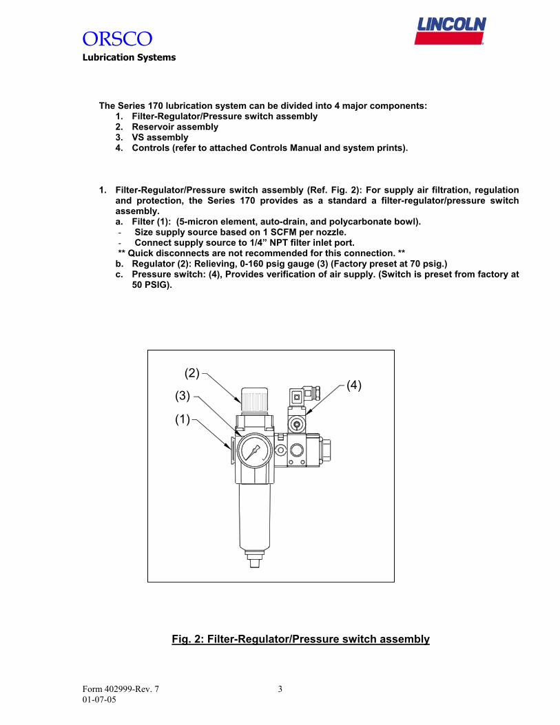
ORSCO Lubrication Systems Tube Connections: Reference system part number for type of tubing.
Nylon tubing - Lubricant line: 3/16” O.D. - Nozzle air supply: 1/4” O.D. (3/8” O.D. for spindle applications). - Ensure that the tube end is cut square and is free of burrs. - Push the tube end through the collet into the fitting. - Continue pushing the tube (firmly) through the o-ring until it bottoms out on the tube stop,
and then pull back. - To disconnect, push the tube into the fitting until it bottoms out on the tube stop. Then,
while holding down the collet, withdraw the tube. - Run feed lines from system to nozzle in such a manner to avoid damage due to friction or
vibration. - Do not connect the feed lines from the system to the nozzle at this time.
Steel tubing - Cut tubing square with a tube cutter or fine-tooth hacksaw. - Lightly deburr the I.D. and O.D. of the tube end to remove burrs and sharp edges. - Slip nut and ferrule over deburred tube end. Be sure the long, straight end of the ferrule
points toward the tube end. - Hold tube steady against internal shoulder of fitting body and tighten nut. - Loosen nut and check proper set (i.e. make sure ferrule is secured to tube). Avoid rotating
the ferrule. -
Bleeding/Priming system: - Open the ball valve (located on the reservoir bottom plate) to allow lubricant to fill the
system. Note: handle on ball valve should be inline with the tubing.
Manual fill systems. - To manually prime:
- Open the bleed petcock, located on the VS manifold end cap. - Allow oil to drain until no air is present, then close petcock. - Manually cycle the injectors – Push in on the Injector adjustment rod, beginning with the
injector closest to the oil feed block – Repeat until lubricant is observed in the nozzle feed line.
- Repeat process to each injector. Fill Lubricant Lines:
- Cycle system until lubricant reaches nozzle position. - Continue to cycle to purge tubing of all contaminants. - Monitor progress – If injectors are not delivering repeat bleed process. - With the system cycling, set the air regulator for 5 PSIG. - Continue to cycle system until lubricant is dispensed out of nozzle tip. - Adjust lubricant volume to desired output. - Adjust air regulator for desired spray pattern.
Form 402999-Rev. 7 6 01-07-05
ORSCO Lubrication Systems
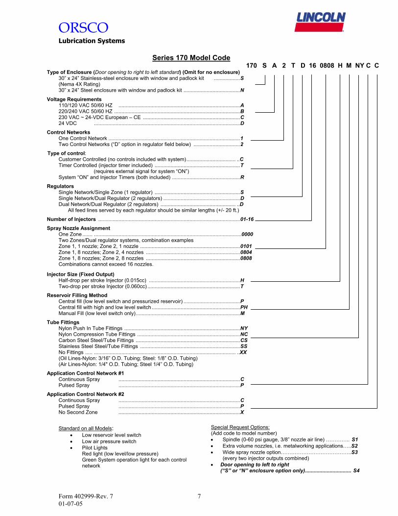
Series 170 Model Code 170 S A 2 T D 16 0808 H M NY C C
Type of Enclosure (Door opening to right to left standard) (Omit for no enclosure) 30” x 24” Stainless-steel enclosure with window and padlock kit ..................S (Nema 4X Rating) 3
0” x 24” Steel enclosure with window and padlock kit .......................................N
Voltage Requirements 110/120 VAC 50/60 HZ ....................................................................................A 220/240 VAC 50/60 HZ .......................................................................................B 230 VAC ~ 24-VDC European – CE ...................................................................C 2
4 VDC .....................................................................................................D
Control Networks One Control Network ...........................................................................................1 T
wo Control Networks (“D” option in regulator field below) ................................2
Type of control: Customer Controlled (no controls included with system).................................. ..C Timer Controlled (injector timer included) ...........................................................T (requires external signal for system “ON”) S
ystem “ON” and Injector Timers (both included) ...............................................R
Regulators Single Network/Single Zone (1 regulator) ...........................................................S Single Network/Dual Regulator (2 regulators) .....................................................D Dual Network/Dual Regulator (2 regulators) .................................................... ..D
All feed lines served by each regulator should be similar lengths (+/- 20 ft.)
Number of Injectors ..................................................................................................01-16
Spray Nozzle Assignment One Zone ....... ......................................................................................................0000 Two Zones/Dual regulator systems, combination examples Zone 1, 1 nozzle; Zone 2, 1 nozzle .....................................................................0101 Zone 1, 8 nozzles; Zone 2, 4 nozzles .................................................................0804 Zone 1, 8 nozzles; Zone 2, 8 nozzles .................................................................0808 Combinations cannot exceed 16 nozzles.
Injector Size (Fixed Output) Half-drop per stroke Injector (0.015cc) ...............................................................H T wo-drop per stroke Injector (0.060cc) ................................................................T
Reservoir Filling Method Central fill (low level switch and pressurized reservoir) .......................................P Central fill with high and low level switch .............................................................PH Manual Fill (low level switch only)........................................................................M
Tube Fittings Nylon Push In Tube Fittings ................................................................................NY Nylon Compression Tube Fittings .......................................................................NC Carbon Steel Steel/Tube Fittings ........................................................................CS Stainless Steel Steel/Tube Fittings .....................................................................SS No Fittings ..... .................................................................................................. ..XX (Oil Lines-Nylon: 3/16” O.D. Tubing; Steel: 1/8” O.D. Tubing) ( Air Lines-Nylon: 1/4" O.D. Tubing; Steel 1/4” O.D. Tubing)
Application Control Network #1 Continuous Spray ....................................................................................C P ulsed Spray ....................................................................................P
Application Control Network #2 Continuous Spray ....................................................................................C Pulsed Spray ....................................................................................P N o Second Zone ....................................................................................X
Standard on all Models:
• Low reservoir level switch • Low air pressure switch • Pilot Lights
Red light (low level/low pressure) Green System operation light for each control network
Special Request Options: (Add code to model number) • Spindle (0-60 psi gauge, 3/8” nozzle air line) ………….. S1 • Extra volume nozzles, i.e. metalworking applications…..S2 • Wide spray nozzle option…………………………………..S3
(every two injector outputs combined) • Door opening to left to right
(“S” or “N” enclosure option only)................................ S4
Form 402999-Rev. 7 7 01-07-05
ORSCO Lubrication Systems
Description
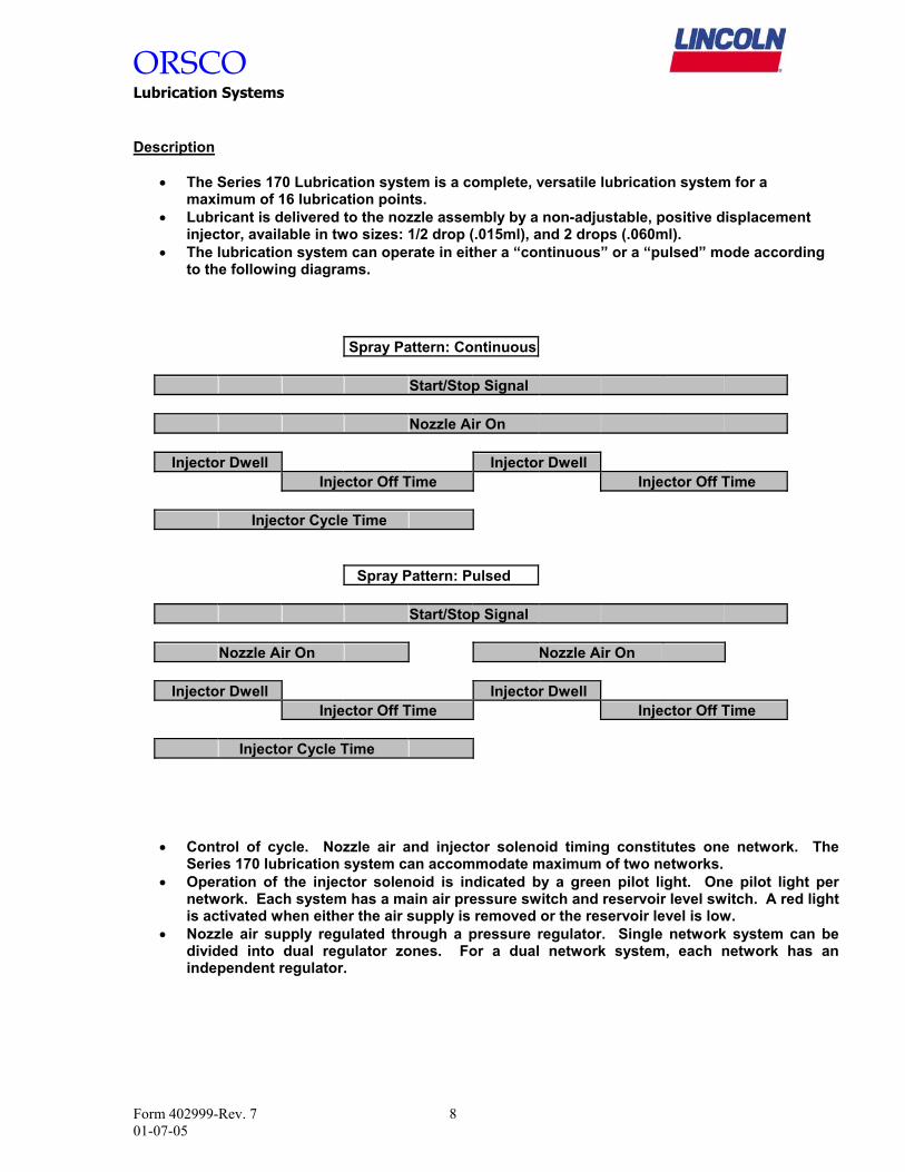
• The Series 170 Lubrication system is a complete, versatile lubrication system for a maximum of 16 lubrication points.
• Lubricant is delivered to the nozzle assembly by a non-adjustable, positive displacement injector, available in two sizes: 1/2 drop (.015ml), and 2 drops (.060ml).
• The lubrication system can operate in either a “continuous” or a “pulsed” mode according to the following diagrams.
Spray Pattern: Continuous Start/Stop Signal Nozzle Air On Injector Dwell Injector Dwell Injector Off Time Injector Off Time Injector Cycle Time Spray Pattern: Pulsed Start/Stop Signal Nozzle Air On Nozzle Air On Injector Dwell Injector Dwell Injector Off Time Injector Off Time Injector Cycle Time
• Control of cycle. Nozzle air and injector solenoid timing constitutes one network. The Series 170 lubrication system can accommodate maximum of two networks.
• Operation of the injector solenoid is indicated by a green pilot light. One pilot light per network. Each system has a main air pressure switch and reservoir level switch. A red light is activated when either the air supply is removed or the reservoir level is low.
• Nozzle air supply regulated through a pressure regulator. Single network system can be divided into dual regulator zones. For a dual network system, each network has an independent regulator.
Form 402999-Rev. 7 8 01-07-05

ORSCO Lubrication Systems
Form 402999-Rev. 7 9 01-07-05
Troubleshooting
Fault: Red Fault Indicator Light is "On" Cause Remedy Low Reservor Level Fill reservoir with clean filtered lubricant. Low Air Pressure Check inlet air supply. Check air filter element, replace if necessary. Switch Malfunction Disconnect cable from air pressure switch, if Fault Indicator changes state, replace pressure switch. Fault Indicator remains "On", replace level switch. Fault: System Pump Indicator Not Cycling/Injectors Cycling Cause Remedy Blown Fuse Inspect fuse (0106FU, 0111FU), replace if necessary. Blown Bulb Inspect bulb (0107LT, 0112LT), replace if necessary. Faulty Connections Inspect wire connections between fuse and indicator light. Fault: System Pump Indicator Cycling/Injectors Not Cycling Cause Remedy No power to injector solenoid Inspect wire connections to injector solenoid (0106SOL, 0111SOL). Injector air supply low Verify air supply from injector solenoid (Manual override on solenoid). Injector internal air pocket Repeat bleed procedure. Injector mechanical failure Replace injector.
ZONE #10107LT 0103LT
FAULTSYSTEM
POWER
0101LTON
W
RG
SERIES 170ENGINEERED LUBRICATION SYSTEMS
DISCONNECT SUPPLY BEFORE SERVICINGWARNING
COUPER L'ALIMANATION AVANT L'ENTRETEINAVERTISSMENT
ET LE DEPANNGE

ORSCO Lubrication Systems
Troubleshooting (con’t)
Fault: System Pump Indicator Not Cycling/Injectors Not Cycling Cause Remedy Power to system Inspect incoming power connections, repair or replace as necessary. Inspect main fuse (0100FU), replace if necessary. Start/Stop Relay Inspect control relay wire connections, including all contacts. Verify power to relay coil, replace coil if necessary. Injector Timer Verify output of Injector Cycle Timer (0105TR, 0110TR). Verify injector Cycle Timer settings (Repeat cycle or single-shot mode). Replace timer if necessary.
Fault: Nozzle Air Line -Low pressure Cause Remedy Open Air Line Reconnect or replace air line Leak at fitting Inspect all fittings, re-seat tubing, or replace fitting if necessary. Regulator pressure low Re-adjust regulator to proper setting. Clogged Air filter Replace filter element Solenoid valve failure Verify power to solenoid (0108SOL, 0113SOL), replace if necessary.
Fault: Nozzle Air Line - High pressure Cause Remedy Blocked air line Inspect tubing for damage, replace if necessary. Regulator pressure high Re-adjust regulator to proper setting. Blocked nozzle tip orifice Inspect nozzle, replace tip if necessary.
Fault: Nozzle Oil Line -Low pressure Cause Remedy Open Oil Line Reconnect or replace oil line Leak at fitting Inspect all fittings, re-seat tubing, or replace fitting if necessary. Nozzle check valve Inspect check ball in nozzle assembly. Clean and re-install. Injector check valve Inspect injector check seal for contamination, clean and re-install.
Fault: Nozzle Oil Line -High pressure Cause Remedy Blocked nozzle tip orifice Inspect nozzle, replace tip if necessary.
Fault: Nozzle Air Line - Line filled with Oil Cause Remedy Nozzle check valve Inspect nozzle assembly for proper installation of check assembly.
Form 402999-Rev. 7 10 01-07-05

ORSCO Lubrication Systems
Series 170 Technical Data
Operating Voltage 24 VDC Injector Cycle Timer (IC) DIP switch selectable 120 VAC ~ 60 Hz. ON-Time Range Factory pre-set @ 0.5 seconds 230 VAC ~ 50/60 Hz. Non-adjustable OFF-Time Range "X1S" 1 to 255 seconds
Operating Current: 24 VDC …. 0.65 - 1.37 FLA "X10S" 10 to 2550 seconds 120 VAC - 60 Hz …. 0.18 - 0.35 FLA Output Type Solid-state normally open 230 VAC - 50/60 Hz …. 0.12 - 0.21 FLA Output Rating 0.7A steady-state, 10 Amp In-rush
Temperature Range: -20° F to 120° F (7° C to 50° C) System Cycle Timer (SC) DIP switch selectable ON-Time Range "X1M" 1 to 15 minutes
Number of Injectors: 16 "X10M" 10 to 150 minutes OFF-Time Range "X10M" 10 to 150 minutes
Reservoir "X1H" 1 to 15 hours Capacity 4000 ml (244 in 3) Output Type Solid-state normally open Tube Material: Acrylic Output Rating 0.7A steady-state, 10 Amp In-rush Seal Material: Buna N Filter: 100 mesh (150 micron)
Lines Level Switch Nozzle Air Supply 1/4" O.D. Nylon Material: Buna N Min. bend radius 22 mm (0.88") Max. switching power: 20 VA Working pressure 17.2 bar(250 psi) @ 23.9° C (75° F) Max. switching current: 0.7 Amp Burst pressure 68.9 bar (1000 psi) @ 23.9° C (75° F) Switch contact (dry state) SPST - N.C.
Nozzle Oil Supply 3/16" O.D. Nylon Lubricant Range: 100-2000 SUS Min. bend radius 19 mm (0.75")
Working pressure 13.8 bar(200 psi) @ 23.9° C (75° F) Injector Output Burst pressure 55.1 bar (800 psi) @ 23.9° C (75° F) Half-Drop: #570-10000 0.015 ml (.001 in3) Double-Drop: #570-10002 0.060 ml (.004 in3)
Thread Sealant Inlet Air pressure 4.5 – 8.3 bar (65-120 psi) Standard Loctite 565 (Teflon-based)
(Non-Teflon based sealant available Main Air filter micron rating: 5 micron upon request) Main Air Regulator (Relieving:
160 psig (Factory preset @ 75 psig)
Air Inlet port 1/4" NPT
Product Certification: CSA C22.2 No. 14-95 – Industrial Control Equipment UL 508 – Industrial Control Equipment
Form 402999-Rev. 7 11 01-07-05

ORSCO Lubrication Systems
Series 170 System Spare Parts List
VS Assembly Spare Parts Orsco Item No. Electrical Spare Parts Orsco Item No. 110/120 AC Injector Valve Block 549-20000 120 VAC Green Pilot Light 642-91027 240/220 AC Injector Valve Block 549-20001 120 VAC Red Pilot Light 642-91028 24 VDC Injector Valve Block 549-20002 120 VAC White Pilot Light 642-99182
110/120 AC Nozzle Air Valve Block 549-20004 24 VDC Green Pilot Light 642-91029 240/220 AC Nozzle Air Valve Block 549-20005 24 VDC Red Pilot Light 642-91030 24 VDC Nozzle Air Valve Block 549-20006 24 VDC White Pilot Light 642-99183
110/120 AC Valve Coil 549-20009 220 VAC Green Pilot Light 642-91032 240/220 AC Valve Coil 549-20011 220 VAC Red Pilot Light 642-91031 24 VDC Valve Coil 549-20010 220 VAC White Pilot Light 642-99292
Solenoid Kit 549-20012 ICAC Injector Timer Module 702-10006 Spool Assembly Kit 549-20013 ICDC Injector Timer Module 702-10007 170/VS/VSR Seal Kit (See below) 570-10084 SCAC System Timer Module 702-10004
SCDC System Timer Module 702-10005 Valve/Regulator Tie Rod 785-43300 Regulator Tie Rod (Dual Regulator Option only) 785-43200 1/4 Amp Fuse 108-07111
1 Amp Fuse 108-07117 Regulator Block Assembly 549-99416 2.5 Amp Fuse 108-91093 Gauge: 30 PSI 495-09185 4 Amp Fuse 108-07110 Gauge: 15 PSI 291-09237 Gauge: 60 PSI 495-91310 30 Amp Disconnect Switch 349-07300 Gauge: 160 PSI 105-09190-0624
Fittings Injector Manifold End Cap 116-43500 Nylon Tube Push In Fittings Valve Manifold End Cap 116-43501 3/16" Tube x 1/8" NPT Straight 549-11055 Oil Feed Block 116-43600 1/4 "Tube x 1/8" NPT Straight 549-11047
Injector Components Nylon Tube Compression Fitting Injector (Half-Drop) 570-10000 3/16" Tube x 1/8" NPT Straight 575-12602 Injector (Double-Drop) 570-10002 1/4 "Tube x 1/8" NPT Straight 575-12670-0982 Injector Tie Rod 785-43100
Steel Tube Fittings (Mat'l: Carbon Steel)Filter/Reservoir Components 1/8" Steel Tube x 1/8" NPT Straight 999-99312 Filter/Regulator, 5 micron 549-99313 1/4" Steel Tube x 1/8" NPT Straight 999-99313 5 Micron Filter Element 549-90013
Steel Tube Fittings (Mat'l: Stainless Steel) Pressure switch (preset @ 50 psig) 549-11013 1/8" Steel Tube x 1/8" NPT SS Ftg. 344-96552
1/4" Steel Tube x 1/8" NPT SS Ftg. 344-96553 Reservoir Base Assembly (w/ Float sw.) 570-89472 Reservoir Float Switch 090-07145 Tubing Reservoir Seals (Buna) 567-99244 3/16" O.D. Nylon (per foot) 565-19185 (Viton, EPDM Seals available upon request) 1/4" O.D. Nylon (per foot) 565-19040-2950
Recommended Spare Parts Quantity 170/VS/VSR Seal Kit includes:Valve Coils 2 (2) Reservoir SealsInjector (Complete Assembly) 2 Valve Interface Seals Air Filter Element: 5 micron 1 Injector Interface Seals (for 8 injectors)Reservoir Assembly (#570-89472) 1Red Pilot Light 1Green Pilot Light 1White Pilot Light 1Timer Module 11/4 Amp Fuse 21 Amp Fuse 24 Amp Fuse 2
Spare Fittings 2 eachWe recommend these items relevantto your system.
Form 402999-Rev. 7 12 01-07-05
ORSCO Lubrication Systems
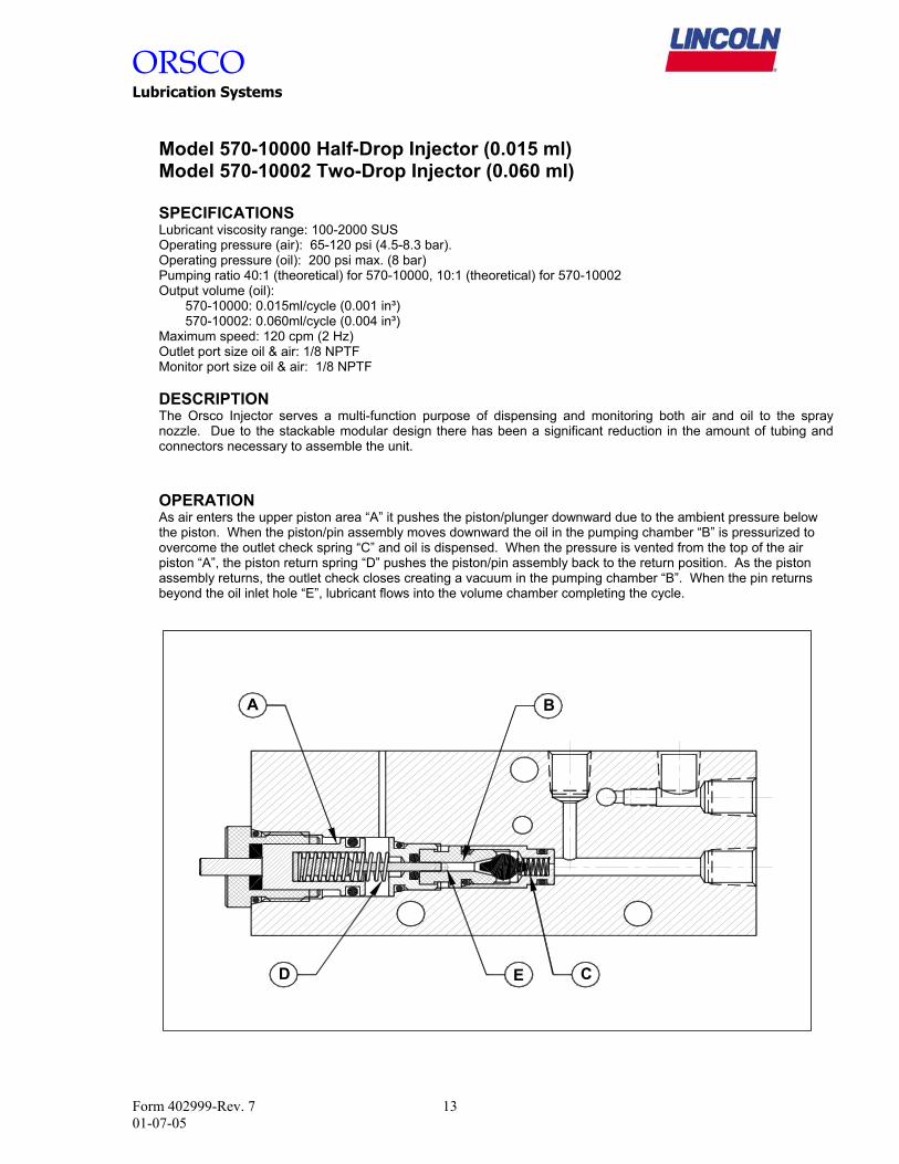
Model 570-10000 Half-Drop Injector (0.015 ml) Model 570-10002 Two-Drop Injector (0.060 ml)
SPECIFICATIONS Lubricant viscosity range: 100-2000 SUS Operating pressure (air): 65-120 psi (4.5-8.3 bar). Operating pressure (oil): 200 psi max. (8 bar) Pumping ratio 40:1 (theoretical) for 570-10000, 10:1 (theoretical) for 570-10002 Output volume (oil): 570-10000: 0.015ml/cycle (0.001 in³) 570-10002: 0.060ml/cycle (0.004 in³) Maximum speed: 120 cpm (2 Hz) Outlet port size oil & air: 1/8 NPTF Monitor port size oil & air: 1/8 NPTF
DESCRIPTION The Orsco Injector serves a multi-function purpose of dispensing and monitoring both air and oil to the spray nozzle. Due to the stackable modular design there has been a significant reduction in the amount of tubing and connectors necessary to assemble the unit. OPERATION As air enters the upper piston area “A” it pushes the piston/plunger downward due to the ambient pressure below the piston. When the piston/pin assembly moves downward the oil in the pumping chamber “B” is pressurized to overcome the outlet check spring “C” and oil is dispensed. When the pressure is vented from the top of the air piston “A”, the piston return spring “D” pushes the piston/pin assembly back to the return position. As the piston assembly returns, the outlet check closes creating a vacuum in the pumping chamber “B”. When the pin returns beyond the oil inlet hole “E”, lubricant flows into the volume chamber completing the cycle.
A B
CD E
Form 402999-Rev. 7 13 01-07-05

ORSCOLubr
Form 4001-07-05
ication Systems
2999-Rev. 7 14
Oil Inlet from reservoir
Valve/Regulator Assembly Tie-rods
System air supply Inlet port
Valve En
Inv
VS Assembly: Adding or replacing an injector 1). Remove #10-32 B.H.C.S. from Injector End Cap. 2). Remove Injector End Cap. 3). To replace injector, simply remove existing injector To add an injector, thread one injector tie-rod (three Install additional injector (ensure seals are seated pr4). Install Injector End Cap. Install #10-32 B.H.C.S..
5). Re-bleed VS assembly.
d Cap
jector Air alve
Nozz
Injector
and replace req’d per injoperly).
le Air valve
Nozzle air supply regulator
Oil Feed Block
Injector output to nozzle
Air supply outlet to nozzle
Injector End Cap
Injector Tie-Rods
with new (ensure seals are seated properly). ector) onto each existing tie-rod assembly.

ORSCO Lubrication Systems
Notes
Form 402999-Rev. 7 15 01-07-05


![[Tech-lubrication]Lubrication Inst for BEVT S1501CII ... · Microsoft Word - [Tech-lubrication]Lubrication Inst for BEVT S1501CII_20130613R02.doc Author: EHickman Created Date: 11/7/2013](https://static.fdocuments.us/doc/165x107/5f063c3e7e708231d416f958/tech-lubricationlubrication-inst-for-bevt-s1501cii-microsoft-word-tech-lubricationlubrication.jpg)