SERIES 1180 SERIES 1180 - Farnell element14 · Hysteresis 10 % typ. Supply voltage range U. B . 10...
14
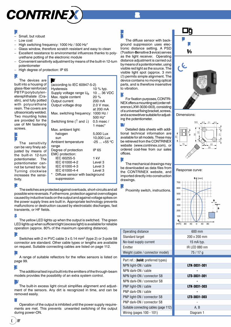
Detaileddatasheetsforthesepr oductscanbefoundontheCONTRINEXwebsite 8 4 Ataglance: − Short: housing length 50 mm (cable connection) / 63.5 mm (con- nector model) − Long operating distances − High switching frequency: 1000 Hz / 500 Hz* − Glass window, therefore scratch resistant and easy to clean − Excellent resistance to environmental influences thanks to polyure- thane potting of the electronic module − Convenient sensitivity adjustment by means of the built-in potentio- meter (diffuse sensors; optional for other models) − High degree of protection: IP 67 Construction The devices are built into chromed- plated brass hou- sings, and encapsu- lated in polyurethane. The electronic module is constructed using SMD technology on a ceramic-free epo- xy substrate, and is therefore insensitive to shock. Sensitivity setting The sensitivity can be adjusted by means of the built-in potentiometer (ener- getic diffuse sensors; optional for other mo- dels). Turning clock- wise increases the sensitivity. Operating distancead justment The operating distance can be adjusted by means of the built-in potentiometer (diffuse sensors with background suppression). Turning clockwise increases the operating distance. Protection The switches are protected against overloads, short-circuits and all possible wire reversals. Furthermore, protection against overvoltages caused by inductive loads on the output and against voltage spikes on the power supply lines are built in. Malfunctions or destruction caused by electrostatic discharges, fast transients, or HF fields, are prevented by appropriate technology. LED The yellow LED lights up when the output is switched on. The green LED lights up when sufficient light is available for reliable operation (approx. 80% of the maximum operating distance). Connection Switches with 2 m PVC cable 3 x 0.34mm 2 (type 8) or 4 x 0.25 mm 2 (type 12) for through-beam sensors, or 4-pole S12 connector are standard. Other cable types or lengths are available on request. Suitable connecting cables are listed on page 112. Reflectors A range of suitable reflectors for the reflex sensors is listed on page 99. T estinput The additional test input built into the emitters of the through-beam models provides the possibility of an extra system control. T echnicaldata: (according to IEC 60947-5-2) Hysteresis 10 % typ. Supply voltage range U B 10 ... 36 VDC Max. ripple content 20 % Output current 200 mA Output voltage drop 2.0 V max. at 200 mA Max. switching frequency 1,000 Hz / 500 Hz* Switching time (↑ and ↓) 0.5 msec / 1 msec* Max. ambient light: halogen 5,000 Lux sun 10,000 Lux Ambient temperature -25 ... +55 o C range Degree of protection IP 67 EMC protection: IEC 60255-5 1 kV IEC 61000-4-2 Level 2 IEC 61000-4-3 Level 3 IEC 61000-4-4 Level 3 * Diffuse sensor with background suppression M8 Diffusesensor energetic 6mm Excesslightcontrol The built-in excess light circuit simplifies alignment and adjustment of the sensors. Any eventual dirt on the sensing faces is recognized in time, and can be removed easily. PowerONreset Operation of the output is in- hibited until the power supply re- quirements are met. This prevents unwanted switching of the output during power-ON. Background suppression The diffuse sensor with background suppression uses electronic distance setting. A PSD (P osition-S ensitive D evice) serves as the light receiver. Operating distance adjustment is carried out by means of a po- tentiometer, using visible red light as the source. The visible light spot (approx. 3 mm ∅) permits simple alignment. The device contains no moving optical parts, and is there- fore insensitive to vibration. Datasheets Detailed data sheets with ad- ditional technical information are available for all models. These may be retrieved from the CONTRINEX website (www.contrinex.com), or ordered cost-free from our sales offices. Drawings The mechanical drawings may be downloaded as data files from the CONTRINEX website, and im- ported directly into construction drawings. Deliverypackage Proximity switch, 2 fixing nuts, instructions. LTK-1180-301 - LTS-1180-301 - LTK-1180-303 - LTS-1180-303 - G, H, K, L Diagram 1 600 mm 200 x 200 mm white 15 mA typ. LED red 660 nm 115 / 40 g Response curve: SERIES 8 Part ref.: (bold: preferred types) NPN light-ON / cable NPN dark-ON / cable NPN light-ON / connector S12 NPN dark-ON / connector S12 PNP light-ON / cable PNP dark-ON / cable PNP light-ON / connector S12 PNP dark-ON / connector S12 Suitable connecting cables (page 112) Wiring (pages 100 - 101) Operating distance Standard target No-load supply current Emitter Weight (cable / connector model)
Transcript of SERIES 1180 SERIES 1180 - Farnell element14 · Hysteresis 10 % typ. Supply voltage range U. B . 10...

Detailed data sheets for these products can be found on the CONTRINEX website:84 http:// www.contrinex.com 85
1
Inductiveproxim
ity switches
2
Photoelectricproxim
ity switches
3
Optical fibers
4
Connecting cables
5
Accessories
6
Glossary
7
Index
At a glance:− Short: housing length 50 mm (cable connection) / 63.5 mm (con-
nector model)− Long operating distances− High switching frequency: 1000 Hz / 500 Hz*− Glass window, therefore scratch resistant and easy to clean− Excellent resistance to environmental influences thanks to polyure-
thane potting of the electronic module− Convenient sensitivity adjustment by means of the built-in potentio-
meter (diffuse sensors; optional for other models)− High degree of protection: IP 67
ConstructionThe devices are
built into chromed-plated brass hou-sings, and encapsu-lated in polyurethane. The electronic module is constructed using SMD technology on a ceramic-free epo-xy substrate, and is therefore insensitive to shock.
Sensitivity setting
The sensitivity can be adjusted by means of the built-in potentiometer (ener-getic diffuse sensors; optional for other mo-dels). Turning clock-wise increases the sensitivity.
Operating distance ad-justment
The operating distance can be adjusted by means of the built-in potentiometer (diffuse sensors with background suppression). Turning clockwise increases the operating distance.
ProtectionThe switches are protected against overloads, short-circuits and all
possible wire reversals. Furthermore, protection against overvoltages caused by inductive loads on the output and against voltage spikes on the power supply lines are built in. Malfunctions or destruction caused by electrostatic discharges, fast transients, or HF fields, are prevented by appropriate technology.
LEDThe yellow LED lights up when the output is switched on. The green
LED lights up when sufficient light is available for reliable operation (approx. 80% of the maximum operating distance).
ConnectionSwitches with 2 m PVC cable 3 x 0.34mm2 (type 8) or 4 x 0.25
mm2 (type 12) for through-beam sensors, or 4-pole S12 connector are standard. Other cable types or lengths are available on request. Suitable connecting cables are listed on page 112.
ReflectorsA range of suitable reflectors for the reflex sensors is listed on
page 99.
Test inputThe additional test input built into the emitters of the through-beam
models provides the possibility of an extra system control.
Technical data:(according to IEC 60947-5-2)Hysteresis 10 % typ.Supply voltage range UB 10 ... 36 VDCMax. ripple content 20 %Output current 200 mAOutput voltage drop 2.0 V max. at 200 mAMax. switching frequency 1,000 Hz / 500 Hz*Switching time (↑ and ↓) 0.5 msec / 1 msec*Max. ambient light: halogen 5,000 Lux sun 10,000 LuxAmbient temperature -25 ... +55 oCrangeDegree of protection IP 67EMC protection: IEC 60255-5 1 kV IEC 61000-4-2 Level 2 IEC 61000-4-3 Level 3 IEC 61000-4-4 Level 3* Diffuse sensor with background suppression
M18Diffuse sensor,
energetic
600 mm
Excess light controlThe built-in excess light
circuit simplifies alignment and adjustment of the sensors. Any eventual dirt on the sensing faces is recognized in time, and can be removed easily.
Power-ON resetOperation of the output is in-
hibited until the power supply re-quirements are met. This prevents unwanted switching of the output during power-ON.
Backgroundsuppression
The diffuse sensor with background suppression uses electronic distance setting. A PSD (Position-Sensitive Device) serves as the light receiver. Operating distance adjustment is carried out by means of a po-tentiometer, using visible red light as the source. The visible light spot (approx. 3 mm ∅) permits simple alignment. The device contains no moving optical parts, and is there-fore insensitive to vibration.
Data sheetsDetailed data sheets with ad-
ditional technical information are available for all models. These may be retrieved from the CONTRINEX website (www.contrinex.com), or ordered cost-free from our sales offices.
DrawingsThe mechanical drawings may
be downloaded as data files from the CONTRINEX website, and im-ported directly into construction drawings.
Delivery packageProximity switch, 2 fixing nuts,
instructions.
LTK-1180-301-
LTS-1180-301-
LTK-1180-303-
LTS-1180-303-
G, H, K, LDiagram 1
600 mm200 x 200 mm white
15 mA typ.LED red 660 nm
115 / 40 g
Response curve:
SERIES 1180 SERIES 1180
Part ref.: (bold: preferred types)NPN light-ON / cableNPN dark-ON / cableNPN light-ON / connector S12NPN dark-ON / connector S12PNP light-ON / cablePNP dark-ON / cablePNP light-ON / connector S12PNP dark-ON / connector S12Suitable connecting cables (page 112)Wiring (pages 100 - 101)
Operating distanceStandard targetNo-load supply currentEmitterWeight (cable / connector model)
Detailed data sheets for these products can be found on the CONTRINEX website:84 http:// www.contrinex.com 85
1Inductive
proximity sw
itches
2
Photoelectricproxim
ity switches
3
Optical fibers
4
Connecting cables
5
Accessories
6
Glossary
7
Index
M18x1
4
29
7 ,8S W
24 5 0
LED
Ø 4,5
M18Through-beam sensor
20,000 mm
[mm]
0 4020 8060 120100
16
12
8
4
0 [mm]
M18Reflex sensor
2,000 mm
* receiver only
[mm]a
24002200200018001600140012001000800600400200
40 20 0 20 40
a
s
[mm]s
LHK-1180-301-
LHS-1180-301-
LHK-1180-303-
LHS-1180-303-
G, H, K, LDiagram 1
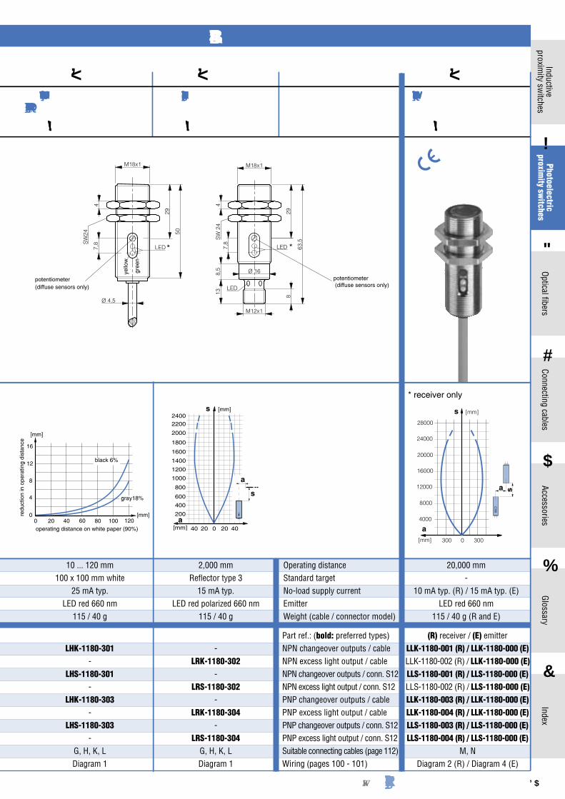
10 ... 120 mm 100 x 100 mm white
25 mA typ.LED red 660 nm
115 / 40 g
2,000 mm Reflector type 3
15 mA typ.LED red polarized 660 nm
115 / 40 g
20,000 mm-
10 mA typ. (R) / 15 mA typ. (E)LED red 660 nm
115 / 40 g (R and E)
-LRK-1180-302
-LRS-1180-302
-LRK-1180-304
-LRS-1180-304
G, H, K, LDiagram 1
redu
ctio
n in
ope
ratin
g di
stan
ce
operating distance on white paper (90%)
black 6%
gray18%
SERIES 1180
M18Diffuse sensor with
background suppression
10 ... 120 mm
potentiometer (diffuse sensors only)
potentiometer (diffuse sensors only)
yello
w
gree
n
4
LED
SW24
63,5
298
Ø 16
LED
M18x1
M12x1
138,
57 ,
8
Operating distanceStandard targetNo-load supply currentEmitterWeight (cable / connector model)
Part ref.: (bold: preferred types)NPN changeover outputs / cableNPN excess light output / cableNPN changeover outputs / conn. S12NPN excess light output / conn. S12PNP changeover outputs / cablePNP excess light output / cablePNP changeover outputs / conn. S12PNP excess light output / conn. S12Suitable connecting cables (page 112)Wiring (pages 100 - 101)
(R) receiver / (E) emitterLLK-1180-001 (R) / LLK-1180-000 (E)LLK-1180-002 (R) / LLK-1180-000 (E)LLS-1180-001 (R) / LLS-1180-000 (E)LLS-1180-002 (R) / LLS-1180-000 (E)LLK-1180-003 (R) / LLK-1180-000 (E)LLK-1180-004 (R) / LLK-1180-000 (E)LLS-1180-003 (R) / LLS-1180-000 (E)LLS-1180-004 (R) / LLS-1180-000 (E)
M, NDiagram 2 (R) / Diagram 4 (E)
[mm]
28000
24000
20000
16000
12000
8000
4000
0300 300[mm]
s
a
a s
* *

Detailed data sheets for these products can be found on the CONTRINEX website:86 http:// www.contrinex.com 87
1
Inductiveproxim
ity switches
2
Photoelectricproxim
ity switches
3
Optical fibers
4
Connecting cables
5
Accessories
6
Glossary
7
Index
At a glance:− Right-angle sensing− Compact, robust and fully integrated sensing head− Easy installation: Fixing nuts can be mounted from both ends− Technical data identical to corresponding devices with axial light
emission− Excellent resistance to environmental influences thanks to poly-
urethane potting of the electronic module− Glass window, therefore scratch resistant and easy to clean− High degree of protection: IP 67
ConstructionThe devices are
built into chromed-plated brass hous-ings, and encapsula-ted in polyurethane. The electronic mod-ule is constructed us-ing SMD technology on a ceramic-free epoxy substrate, and is therefore in-sensitive to shock.
Sensibility setting
The sensitivity can be adjusted by means of the built-in potentiometer (diffuse sensors; optional for other models). Turn-ing clockwise increas-es the sensitivity.
Operating dis-tance adjust-ment
The operating dis-tance can be adjusted by means of the built-in potentiometer (diffuse sensors with background suppression). Turning clockwise increases the operating distance.
ProtectionThe switches are protected against overloads, short-circuits and all
possible wire reversals. Furthermore, protection against overvoltages caused by inductive loads on the output and against voltage spikes on the power supply lines are built in. Malfunctions or destruction caused by electrostatic discharges, fast transients, or HF fields, are prevented by appropriate technology.
LEDThe yellow LED lights up when the output is switched on. The
green LED lights up when sufficient light is available for reliable operation (approx. 80% of the maximum operating distance).
ConnectionSwitches with 2 m PVC cable 3 x 0.34mm2 (type 8) or 4 x 0.25
mm2 (type 12) for through-beam sensors, or 4-pole S12 connector are standard. Other cable types or lengths are available on request. Suitable connecting cables are listed on page 112.
ReflectorsA range of suitable reflectors for the reflex sensors is listed on
page 99.
Test inputThe additional test input built into the emitters of the through-beam
models provides the possibility of an extra system control.
Excess light controlThe built-in excess light
circuit simplifies alignment and adjustment of the sensors. Any eventual dirt on the sensing faces is recognized in time, and can be removed easily.
Power-ON resetOperation of the output is in-
hibited until the power supply re-quirements are met. This prevents unwanted switching of the output during power-ON.
Background suppressionThe diffuse sensor with back-
ground suppression uses electro-nic distance setting. A PSD (Po-sition-Sensitive Device) serves as the light receiver. Operating distance adjustment is carried out by means of a potentiometer, us-ing visible red light as the source. The visible light spot (approx. 3 mm ∅) permits simple alignment. The device contains no moving optical parts, and is therefore insensitive to vibration.
Data sheetsDetailed data sheets with ad-
ditional technical information are available for all models. These may be retrieved from the CONTRINEX website (www.contrinex.com), or ordered cost-free from our sales offices.
DrawingsThe mechanical drawings may
be downloaded as data files from the CONTRINEX website, and im-ported directly into construction drawings.
Delivery packageProximity switch, 2 fixing nuts,
instructions.
LTK-1180W-301-
LTS-1180W-301-
LTK-1180W-303-
LTS-1180W-303-
G, H, K, LDiagram 1
600 mm200 x 200 mm white
15 mA typ.LED red 660 nm
123 / 56 g
Response curve:
SERIES 1180 W SERIES 1180 W
Technical data:(according to IEC 60947-5-2)Hysteresis 10 % typ.Supply voltage range UB 10 ... 36 VDCMax. ripple content 20 %Output current 200 mAOutput voltage drop 2.0 V max. at 200 mAMax. switching frequency 1,000 Hz / 500 Hz*Switching time (↑ and ↓) 0.5 msec / 1 msec*Max. ambient light: halogen 5,000 Lux sun 10,000 LuxAmbient temperature -25 ... +55 oCrangeDegree of protection IP 67EMC protection: IEC 60255-5 1 kV IEC 61000-4-2 Level 2 IEC 61000-4-3 Level 3 IEC 61000-4-4 Level 3* Diffuse sensor with background suppression
M18WDiffuse sensor,
energetic
600 mm
[mm]s
[mm]a
700
600
500
400
300
200
100
80 40 0 8040
s
a
Part ref.: (bold: preferred types)NPN light-ON / cableNPN dark-ON / cableNPN light-ON / connector S12NPN dark-ON / connector S12PNP light-ON / cablePNP dark-ON / cablePNP light-ON / connector S12PNP dark-ON / connector S12Suitable connecting cables (page 112)Wiring (pages 100 - 101)
Operating distanceStandard targetNo-load supply currentEmitterWeight (cable / connector model)


Detailed data sheets for these products can be found on the CONTRINEX website:88 http:// www.contrinex.com 89
1
Inductiveproxim
ity switches
2
Photoelectricproxim
ity switches
3
Optical fibers
4
Connecting cables
5
Accessories
6
Glossary
7
Index
At a glance:− Small, but robust− Long operating distances− High switching frequency: 1000 Hz / 500 Hz*− Glass window, therefore scratch resistant and easy to clean− Excellent resistance to environmental influences thanks to poly-
urethane potting of the electronic module− Convenient sensitivity adjustment by means of the built-in 12-turn
potentiometer− High degree of protection: IP 67
ConstructionThe devices are
built into a housing of glass-fiber reinforced PBTP/polybutylen-eterephthalate (Cra-stin), and fully potted with polyurethane resin. The covers are ultrasonically welded. Two mounting holes are provided for the use of M4 fastening screws. A universal mounting bracket as well as screws are included with every switch.
Sensitivity setting
The sensitivity can be very finely adjusted by means of the built-in 12-turn potentiome-ter. The potentiometer cannot be turned too far. Turning clock-wise increases the sensitivity.
ProtectionThe switches are protected against overloads, short-circuits and all
possible wire reversals. Furthermore, protection against overvoltages caused by inductive loads on the output and against voltage spikes on the power supply lines are built in. Appropriate technology prevents malfunctions or destruction caused by electrostatic discharges, fast transients, or HF fields.
LEDThe yellow LED lights up when the light-ON output is switched.
The green LED lights up if the receiver gets enough light (excess light) for reliable operation. At the same time the corresponding out-put (types -102 and -104 only) is switched.
ConnectionSwitches with 3 m PVC cable 4 x 0.14 mm2 (type 2) or 4-pole S8
connector are standard. Other cable types or lengths are available on request. Suitable connecting cables are listed on page 112.
ReflectorsA range of suitable reflectors for the reflex sensors is listed on
page 99.
Test inputThe additional test input built into the emitters of the through-beam
models provides the possibility of an extra system control.
Excess light controlThe built-in excess light circuit (separate output for types -102
and -104) simplifies alignment and adjustment of the sensors. Any dirt is recognized in time, and can be removed easily.
Power-ON resetOperation of the output is in-
hibited until the power supply re-quirements are met. This prevents unwanted switching of the output during power-ON.
Background suppressionThe diffuse sensor with back-
ground suppression uses electro-nic distance setting. A PSD (Po-sition-Sensitive Device) serves as the light receiver. Operating distance adjustment is carried out by means of a potentiometer, us-ing visible red light as the source. The visible light spot (approx. 3 mm ∅) permits simple alignment. The device contains no moving optical parts, and is therefore insensitive to vibration.
Data sheetsDetailed data sheets with
additional technical informa-tion are available for all mod-els. These may be retrieved from the CONTRINEX website (www.contrinex.com), or ordered cost-free from our sales offices.
DrawingsThe mechanical drawings may
be downloaded as data files from the CONTRINEX website, and im-ported directly into construction drawings.
Delivery packageProximity switch, mounting
bracket, screws, washers and nuts, screwdriver, instructions.
Dimensions:
Response curve:
[mm]
1200
1000
800
600
400
200
050100150 50 100 150[mm]
s
a
a
s
M4
4,5
308
22
4,5 21 4,5
8 2230
4,5
21
15
20
14
LTK-3030-101LTK-3030-102LTS-3030-101LTS-3030-102LTK-3030-103LTK-3030-104LTS-3030-103LTS-3030-104
E, F Diagram 2
1,200 mm200 x 200 mm
15 mA typ.IR LED 880 nm
75 / 17 g
SERIES 3030
30x30Diffuse sensor,
energetic
1,200 mm
Part ref.: (bold: preferred types)NPN changeover outputs / cableNPN excess light output / cableNPN changeover outputs / conn. S8NPN excess light output / conn.S8PNP changeover outputs / cablePNP excess light output / cablePNP changeover outputs / conn. S8PNP excess light output / conn. S8Suitable connecting cables (page 112)Wiring (pages 100 - 101)
Operating distanceStandard targetNo-load supply currentEmitterWeight (cable / connector model)
Technical data:(according to IEC 60947-5-2)Hysteresis 10 % typ.Supply voltage range UB 10 ... 36 VDCMax. ripple content 20 %Output current (total of 200 mAboth outputs)Output voltage drop 2.0 V max. at 200 mAMax. switching frequency 1000 Hz / 500 Hz*Switching time (↑ and ↓) 0.5 msec / 1 msec*Max. ambient light: halogen 5,000 Lux sun 10,000 LuxAmbient temperature -25 ... +55 oCrangeDegree of protection IP 67EMC protection: IEC 60255-5 1 kV IEC 61000-4-2 Level 2 IEC 61000-4-3 Level 3 IEC 61000-4-4 Level 3* Diffuse sensor with background suppression

Detailed data sheets for these products can be found on the CONTRINEX website:88 http:// www.contrinex.com 89
1Inductive
proximity sw
itches
2
Photoelectricproxim
ity switches
3
Optical fibers
4
Connecting cables
5
Accessories
6
Glossary
7
Index
[mm]
04080 40 80[mm]a
a
s
s4000
3500
3000
2500
2000
1500
1000
500
[mm]
14000
12000
10000
8000
6000
4000
2000
0400800 400 800[mm]
s
a
a s
[mm]
120
100
80
60
40
20
02040 20 40[mm]
s
a
a
s
15
20
14
4,5
308
22
4,5 21 4,5
8 2230
4,5
21
M4
5 15
M4
20
14
4,5
308
22
4,5 21 4,5
8 2230
4,5
21
15
20
14
4,5
308
22
4,5 21 4,5
8 2230
4,5
21
M4
5
20
M4 4,5 21 4,5
8 2230
4,5
4,5
21
15
30
82214
7
8
16
24
32
00 40 80 120 160
[mm]
[mm]
redu
ctio
n in
ope
ratin
g di
stan
ce
operating distance with white paper (90%)
gray 18 %
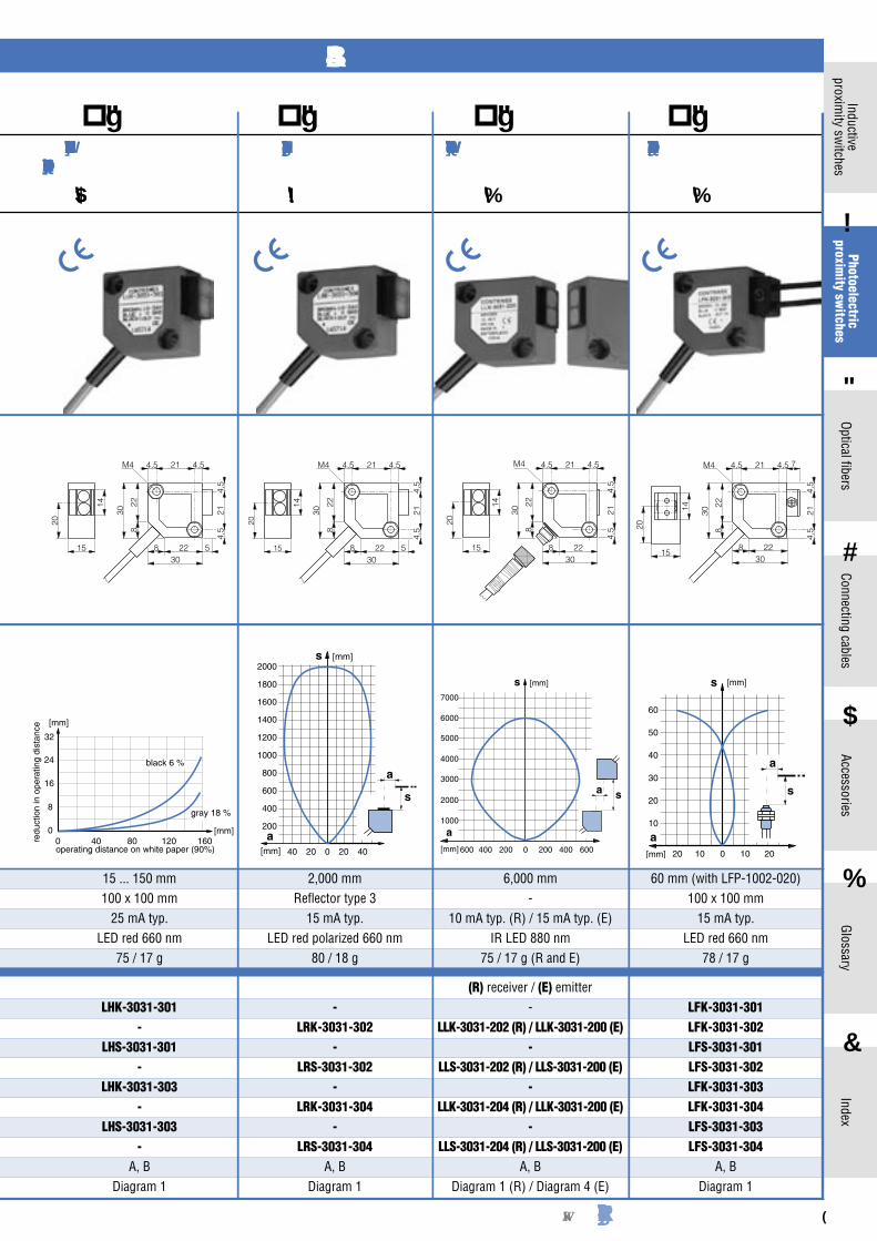
120 mm (with LFP-1002-020)100 x 100 mm
15 mA typ.LED red 660 nm
78 / 18 g
12,000 mm-
10 mA typ. (R) / 15 mA typ. (E)IR LED 880 nm
75 / 17 g (R and E)
LFK-3030-101LFK-3030-102LFS-3030-101LFS-3030-102LFK-3030-103LFK-3030-104LFS-3030-103LFS-3030-104
E, F Diagram 2
(R) receiver / (E) emitterLLK-3030-001 (R) / LLK-3030-000 (E)LLK-3030-002 (R) / LLK-3030-000 (E)LLS-3030-001 (R) / LLS-3030-000 (E)LLS-3030-002 (R) / LLS-3030-000 (E)LLK-3030-003 (R) / LLK-3030-000 (E)LLK-3030-004 (R) / LLK-3030-000 (E)LLS-3030-003 (R) / LLS-3030-000 (E)LLS-3030-004 (R) / LLS-3030-000 (E)
E, F Diagram 2 (R) / Diagram 4 (E)
4,000 mm Reflector type 3
15 mA typ.LED red polarized 660 nm
80 / 18 g
LRK-3030-101LRK-3030-102LRS-3030-101LRS-3030-102LRK-3030-103LRK-3030-104LRS-3030-103LRS-3030-104
E, F Diagram 2
LHK-3030-101LHK-3030-102LHS-3030-101LHS-3030-102LHK-3030-103LHK-3030-104LHS-3030-103LHS-3030-104
E, F Diagram 2
15 ... 150 mm100 x 100 mm
25 mA typ.LED red 660 nm
75 / 17 g
SERIES 3030
30x30Reflex sensor
4,000 mm
30x30Through-beam sensor
12,000 mm
30x30Diffuse sensor with
background suppression
15 ... 150 mm
30x30Fiber-optic amplifier
120 mm
black 6 %
Detailed data sheets for these products can be found on the CONTRINEX website:90 http:// www.contrinex.com 91
1
Inductiveproxim
ity switches
2
Photoelectricproxim
ity switches
3
Optical fibers
4
Connecting cables
5
Accessories
6
Glossary
7
Index
At a glance:− Small, but robust− Low cost− High switching frequency: 1000 Hz / 500 Hz*− Glass window, therefore scratch resistant and easy to clean− Excellent resistance to environmental influences thanks to poly-
urethane potting of the electronic module− Convenient sensitivity adjustment by means of the built-in 12-turn
potentiometer− High degree of protection: IP 65
ConstructionThe devices are
built into a housing of glass-fiber reinforced PBTP/polybutylen-eterephthalate (Cra-stin), and fully potted with polyurethane resin. The covers are ultrasonically welded. Two mounting holes are provided for the use of M4 fastening screws.
Sensitivity setting
The sensitivity can be very finely ad-justed by means of the built-in 12-turn potentiometer. The potentiometer can-not be turned too far. Turning clockwise increases the sensi-tivity.
ProtectionThe switches are protected against overloads, short-circuits and all
possible wire reversals. Furthermore, protection against overvoltages caused by inductive loads on the output and against voltage spikes on the power supply lines are built in. Appropriate technology prevents malfunctions or destruction caused by electrostatic discharges, fast transients, or HF fields.
LEDThe yellow LED lights up when the output is switched. The green
LED lights up when sufficient light (excess light) is available for reliable operation (approx. 80% of the maximum operating distance).
ConnectionSwitches with 2 m PVC cable 3 x 0.14 mm2 (type 2) or 3-pole S8
connector are standard. Other cable types or lengths are available on request. Suitable connecting cables are listed on page 112.
ReflectorsA range of suitable reflectors for the reflex sensors is listed on
page 99.
Test inputThe additional test input built into the emitters of the through-beam
models provides the possibility of an extra system control.
Excess light controlThe built-in excess light circuit simplifies alignment and adjust-
ment of the sensors. Any dirt is recognized in time, and can be removed easily.
Power-ON resetOperation of the output is inhibited until the power supply require-
ments are met. This prevents unwanted switching of the output during power-ON.
Backgroundsuppression
The diffuse sensor with back-ground suppression uses elec-tronic distance setting. A PSD (Position-Sensitive Device) serves as the light receiver. Operating distance adjustment is carried out by means of a potentiometer, using visible red light as the source. The visible light spot (approx. 3 mm ∅) permits simple alignment. The device contains no moving optical parts, and is therefore insensitive to vibration.
FixingFor fixation purposes, CONTRI-
NEX offers a mounting set (order ref-erence LXW-3030-003), consisting of a universal fixing bracket, screws, and a screwdriver suitable for adjust-ing the potentiometer.
Data sheetsDetailed data sheets with addi-
tional technical information are available for all models. These may be retrieved from the CONTRINEX website (www.contrinex.com), or ordered cost-free from our sales offices.
DrawingsThe mechanical drawings may
be downloaded as data files from the CONTRINEX website, and imported directly into construction drawings.
Delivery packageProximity switch, instructions.
Dimensions:
Response curve:
[mm]
700
600
500
400
300
200
100
04080 40 80[mm]
s
a
a
s
M4
4,5
308
22
4,5 21 4,5
8 2230
4,5
21
15
20
14
600 mm200 x 200 mm
15 mA typ.IR LED 880 nm
75 / 17 g
LTK-3031-301-
LTS-3031-301-
LTK-3031-303-
LTS-3031-303-
A, BDiagram 1
SERIES 3031
30x30DIffuse sensor,
energetic
600 mm
Part ref.: (bold: preferred types)NPN light-ON / cableNPN dark-ON / cableNPN light-ON / connector S8NPN dark-ON / connector S8PNP light-ON / cablePNP dark-ON / cablePNP light-ON / connector S8PNP dark-ON / connector S8Suitable connecting cables (page 112)Wiring (pages 100 - 101)
Operating distanceStandard targetNo-load supply currentEmitterWeight (cable / connector model)
Technical data:(according to IEC 60947-5-2)Hysteresis 10 % typ.Supply voltage range UB 10 ... 36 VDCMax. ripple content 20 %Output current 200 mAOutput voltage drop 2.0 V max. at 200 mAMax. switching frequency: 1000 Hz / 500 Hz*Switching time (↑ and ↓) 0.5 msec / 1 msec*Max. ambient light: halogen 5,000 Lux sun 10,000 LuxAmbient temperature -25 ... +55 oCrangeDegree of protection IP 65EMC protection: IEC 60255-5 1 kV IEC 61000-4-2 Level 3 IEC 61000-4-3 Level 3 IEC 61000-4-4 Level 3* Diffuse sensor with background suppression
Detailed data sheets for these products can be found on the CONTRINEX website:90 http:// www.contrinex.com 91
1Inductive
proximity sw
itches
2
Photoelectricproxim
ity switches
3
Optical fibers
4
Connecting cables
5
Accessories
6
Glossary
7
Index
[mm]a
2000
1800
1600
1400
1200
1000
800
600
400
200
[mm]s
40 20 0 20 40
a
s
[mm]7000
6000
5000
4000
3000
2000
1000
0200400600 200 400 600
s
a s
[mm]
a
[mm]
60
50
40
30
20
10
01020 10 20[mm]
s
a
a
s
15
20
14
4,5
308
22
4,5 21 4,5
8 2230
4,5
21
M4
5 15
20
14
4,5
308
22
4,5 21 4,5
8 2230
4,5
21
M4
5 15
M4
20
14
4,5
308
22
4,5 21 4,5
8 2230
4,5
21
20
M4 4,5 21 4,5
8 2230
4,5
4,5
21
15
308
2214
7
8
16
24
32
00 40 80 120 160
[mm]
[mm]
redu
ctio
n in
ope
ratin
g di
stan
ce
operating distance on white paper (90%)
15 ... 150 mm100 x 100 mm
25 mA typ.LED red 660 nm
75 / 17 g
LHK-3031-301-
LHS-3031-301-
LHK-3031-303-
LHS-3031-303-
A, BDiagram 1
2,000 mm Reflector type 3
15 mA typ.LED red polarized 660 nm
80 / 18 g
-LRK-3031-302
-LRS-3031-302
-LRK-3031-304
-LRS-3031-304
A, BDiagram 1
6,000 mm-
10 mA typ. (R) / 15 mA typ. (E)IR LED 880 nm
75 / 17 g (R and E)
(R) receiver / (E) emitter-
LLK-3031-202 (R) / LLK-3031-200 (E)-
LLS-3031-202 (R) / LLS-3031-200 (E)-
LLK-3031-204 (R) / LLK-3031-200 (E)-
LLS-3031-204 (R) / LLS-3031-200 (E)A, B
Diagram 1 (R) / Diagram 4 (E)
60 mm (with LFP-1002-020)100 x 100 mm
15 mA typ.LED red 660 nm
78 / 17 g
LFK-3031-301LFK-3031-302LFS-3031-301LFS-3031-302LFK-3031-303LFK-3031-304LFS-3031-303LFS-3031-304
A, BDiagram 1
SERIES 3031
30x30Reflex sensor
2,000 mm
30x30Through-beam sensor
6,000 mm
30x30Diffuse sensor with
background suppression
15 ... 150 mm
30x30Fiber-optic amplifier
60 mm
black 6 %
gray 18 %

Detailed data sheets for these products can be found on the CONTRINEX website:92 http:// www.contrinex.com 93
1Inductive
proximity sw
itches
2
Photoelectricproxim
ity switches
3
Optical fibers
4
Connecting cables
5
Accessories
6
Glossary
7
Index
[mm]
4000
5000
6000
3000
2000
1000
0100200 100 200
s
a
s
[mm]a
[mm]
120
140
160
100
80
60
40
20
02040 20 40
s
a
s
[mm]
a
[mm]
14000
12000
10000
8000
6000
4000
2000
0400800 400 800
s
a s
[mm]a
29
19
22
4028
4,5 31 4,5Ø M4
4,5
314,
5
28 512
40
12
16
29
19
22
4028
4,5 31 4,5Ø M4
4,5
314,
5
28 512
40
12
16
29
19
4028
4,5 31 4,5Ø M4
4,5
314,
5
2812
40
12
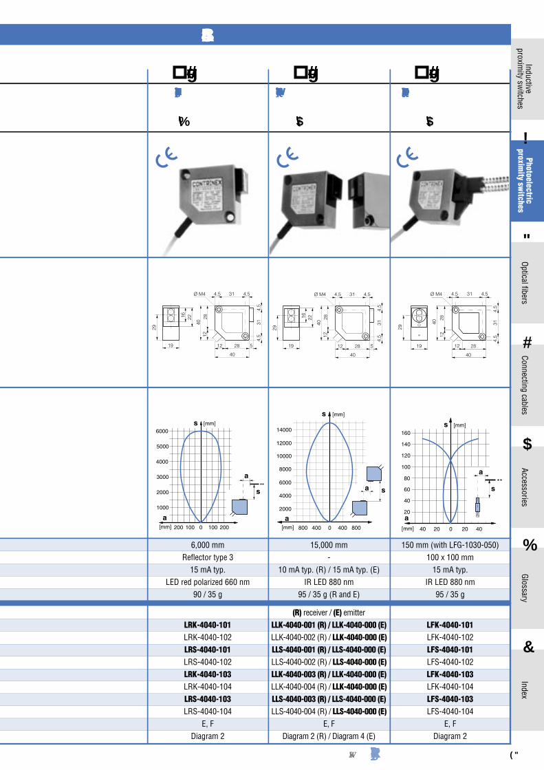
LFK-4040-101LFK-4040-102LFS-4040-101LFS-4040-102LFK-4040-103LFK-4040-104LFS-4040-103LFS-4040-104
E, FDiagram 2
150 mm (with LFG-1030-050)100 x 100 mm
15 mA typ.IR LED 880 nm
95 / 35 g
15,000 mm-
10 mA typ. (R) / 15 mA typ. (E)IR LED 880 nm
95 / 35 g (R and E)
(R) receiver / (E) emitterLLK-4040-001 (R) / LLK-4040-000 (E)LLK-4040-002 (R) / LLK-4040-000 (E)LLS-4040-001 (R) / LLS-4040-000 (E)LLS-4040-002 (R) / LLS-4040-000 (E)LLK-4040-003 (R) / LLK-4040-000 (E)LLK-4040-004 (R) / LLK-4040-000 (E)LLS-4040-003 (R) / LLS-4040-000 (E)LLS-4040-004 (R) / LLS-4040-000 (E)
E, FDiagram 2 (R) / Diagram 4 (E)
6,000 mm Reflector type 3
15 mA typ.LED red polarized 660 nm
90 / 35 g
LRK-4040-101LRK-4040-102LRS-4040-101LRS-4040-102LRK-4040-103LRK-4040-104LRS-4040-103LRS-4040-104
E, FDiagram 2
SERIES 4040
40x40Reflex sensor
6,000 mm
40x40Through-beam sensor
15,000 mm
40x40Fiber-optic amplifier
150 mm


Detailed data sheets for these products can be found on the CONTRINEX website:94 http:// www.contrinex.com 95
1Inductive
proximity sw
itches
2
Photoelectricproxim
ity switches
3
Optical fibers
4
Connecting cables
5
Accessories
6
Glossary
7
Index
SERIES 3060
Dimensions:
Ø 4
6 0
8,5
10
OUTmax
Time
Enter
Signal
ModeStatus
Teach 1Teach 2AdjustDelay
StretchLight-On
SWISS MADE
2,3
6,3
Ø 3,4
46 351 310
,8
3 1,1
4
89
6 0
10
OUTmax
Time
Enter
Signal
ModeStatus
Teach 1Teach 2AdjustDelay
StretchLight-On
SWISS MADE
2,3
6,3
Ø 3,4
46 351 310
,8
Ø 4

Detailed data sheets for these products can be found on the CONTRINEX website:96 http:// www.contrinex.com 97
1
Inductiveproxim
ity switches
2
Photoelectricproxim
ity switches
3
Optical fibers
4
Connecting cables
5
Accessories
6
Glossary
7
Index
At a glance:− Robust universal devices− Long operating distances− High switching frequency: 1000 Hz / 250 Hz*− Reflex sensors using autocollimation principle− Glass window, therefore scratch resistant and easy to clean− The PBTP (Crastin) housing provides exceptional resistance to
environmental influences− Sensitivity adjustment by means of a built-in potentiometer with
calibration scale and reduction gearbox− High degree of protection: IP 67
ConstructionThe devices are
built into a housing of glass-fiber rein-forced PBTP/poly-butyleneterephtha-late (Crastin). For fixing purposes, a number of through holes suitable for M5 screws are pro-vided. The distance between the holes has been chosen for maximum com-patibility with the most commonly available sensors on the market.
Sensitivity setting
The sensitivity can be very finely adjusted by means of the built-in poten-tiometer with cali-bration scale and reduction gearbox. The potentiometer cannot be turned too far. Turning clockwise increases the sensi-tivity.
ProtectionThe switches are protected against overloads, short-circuits and all
possible wire reversals. Furthermore, protection against overvoltages caused by inductive loads on the output and against voltage spikes on the power supply lines are built in. Appropriate technology prevents malfunctions or destruction caused by electrostatic discharges, fast transients, or HF fields.
LEDThe yellow LED lights up when the light-ON output is switched.
The green LED indicates that sufficient light is available for reliable operation (approx. 80% of the maximum operating distance); at the same time, the corresponding output (if available) is switched.
ConnectionAs standard, the devices are delivered with 4-pole or 5-pole S12
connector, or screw terminal. Suitable connecting cables are listed on page 112.
ReflectorsA range of suitable reflectors for the reflex sensors is listed on
page 99.
Test inputThe built-in test input (optional for some models) provides the
possibility of an extra system control.
Excess light controlThe built-in excess light circuit simplifies alignment and adjust-
ment of the sensors. Eventual dirt is recognized in time, and can be removed easily.
Power-ON resetOperation of the output is
inhibited until the power supply requirements are met. This pre-vents unwanted switching of the output during power-ON.
Background suppressionThe diffuse sensor with
background suppression uses electronic distance setting. A PSD (Position-Sensitive Device) serves as the light receiver. Op-erating distance adjustment is carried out by means of a poten-tiometer, using infra-red light as the source. At a distance of 1 m, the light spot has a diameter of approx. 30 mm.
TimerThe timer (optional) allows
selection of switch-on delay, switch-off delay, or pulses; adjust-able from 0.01 ... 1 s (UC models 0.1 ... 10 s).
Data sheetsDetailed data sheets with
additional technical informa-tion are available for all mod-els. These may be retrieved from the CONTRINEX website (www.contrinex.com), or ordered cost-free from our sales offices.
DrawingsThe mechanical drawings may
be downloaded as data files from the CONTRINEX website, and im-ported directly into construction drawings.
Delivery packageProximity switch, instruc-
tions.
[mm]2200
s
[mm]a
0
a
s
200018001600140012001000800600400200
100 100200 200
LTS-6080-101*LTT-6080-101
LTS-6080-151**LTT-6080-151
LTS-6080-103*LTT-6080-103
LTS-6080-153**LTT-6080-153LTS-6080-115LTT-6080-115LTS-6080-165LTT-6080-165
M, N (**with test input: O, P)2 (LTS-...*) / 3 (LTS/LTT-...) / 5 (UC)
2,000 mm400 x 400 mm white
20 mA / 2 VA typ.IR LED 880 nm
100 g
SERIES 6080
Technical data:(according to IEC 60947-5-2)Hysteresis 10 % typ.DC supply voltage range UB 10 ... 36 VDCUC supply voltage range UB 20 ... 265 VAC 20 ... 320 VDCMax. ripple content** 20 %Output current** 200 mAOutput voltage drop** 2.0 V max. at 200 mAMax. switching frequency** 1000 Hz / 250 Hz*Switching time** (↑ and ↓) 0.5 msec / 1 msec*Max. ambient light: halogen 5,000 Lux sun 10,000 LuxAmbient temperature -5 ... +55 oCrangeDegree of protection IP 67EMC protection: IEC 60255-5 1 kV IEC 61000-4-2 Level 3 IEC 61000-4-3 Level 3 IEC 61000-4-4 Level 3
* Diffuse sensor with background suppression** DC models (UC see data sheet)
65x83Diffuse sensor,
energetic
2,000 mm
Response curve:
*** light-ON/dark-ON switchable
Part ref.: (bold: preferred types)DC NPN / connector S12DC NPN / screw terminalDC NPN timer*** / connector S12DC NPN timer*** / screw terminalDC PNP / connector S12DC PNP / screw terminalDC PNP timer*** / connector S12DC PNP timer*** / screw terminalUC relay / connector S12UC relay / screw terminalUC relay / timer***/ connector S12UC relay / timer***/ screw terminalSuitable connecting cables (page 112)Wiring (pages 100 - 101)
Operating distanceStandard targetNo-load supply current DC / UCEmitterWeight