Serial No. 201207160001 CM3218 - NXP Community
14
www.capellamicro.com © Copyright 2011, Capella Microsystems, Inc. Serial No. 201207160001 Equation Chapter 1 Section 1 Rev: 0.82 Revised 2 th -July-2012 Description CM3218 is an advanced ambient light sensor with I 2 C protocol interface and designed by the CMOS process. It is easily operated via a simple I 2 C command. The active interruption feature within the threshold windows setting offers the benefit of eliminating loading of the controller monitor. CM3218 incorporates a photodiode, amplifiers and analog circuits into a single chip. The best spectral sensitivity is used to closely capture real human eye responses. CM3218 has excellent temperature compensation. Its robust refresh rate setting does not need an external RC low pass filter. Software shutdown mode is provided which reduces power consumption to be less than 1μA. CM3218’s operating voltage ranges from 2.7V to 5V and can detect a wide range of ambient light power.. The maximum detective light strength is over 140K Lux. Block Diagram Features • Filtron™ technology adoption : excellent responsivity : close to real human eye responses • High sensitivity: minimum detectable intensity 0.00089 Lux/Bit supports low transmittance(dark) lens design • O-Trim™ technology adoption : ALS output tolerance: ± 10% • Excellent temperature compensation: -40 to 85ºC • High dynamic detection resolution • Standard I 2 C protocol interface • Interruption feature (INT) support Programmable interrupt function with upper and lower thresholds. Adjustable persistence to prevent false triggers. • Fluorescent light flicker immunity • Auto memorization of the last light data before shutdown • Software shutdown mode control • Operation voltage from 2.7V to 5V • Ambient light strength detection range over 140K Lux • Package: OPLGA (2.35 x 1.8 x 1.0 mm) • Lead-free package (RoHS compliant) Applications • Notebook, Tablet, TV • Mobile Phone, Smart-phone, PDA • Automotive Pin Definition <Top View> 1 Ground 4 Rset 2 I 2 C Data 5 I 2 C Clock 3 Interrupt 6 Power CM3218 High Sensitivity I 2 C Ambient Light Sensor Confidential for WT Microelectronics
Transcript of Serial No. 201207160001 CM3218 - NXP Community

www.capellamicro.com © Copyright 2011, Capella Microsystems, Inc.
Serial No. 201207160001
Equation Chapter 1 Section 1
Rev: 0.82 Revised 2th-July-2012
Description
CM3218 is an advanced ambient light sensor with I2C protocol interface and designed by the CMOS process. It is easily operated via a simple I2C command. The active interruption feature within the threshold windows setting offers the benefit of eliminating loading of the controller monitor.
CM3218 incorporates a photodiode, amplifiers and analog circuits into a single chip. The best spectral sensitivity is used to closely capture real human eye responses. CM3218 has excellent temperature compensation. Its robust refresh rate setting does not need an external RC low pass filter. Software shutdown mode is provided which reduces power consumption to be less than 1μA. CM3218’s operating voltage ranges from 2.7V to 5V and can detect a wide range of ambient light power.. The maximum detective light strength is over 140K Lux.
Block Diagram
Features
• Filtron™ technology adoption : excellent responsivity : close to real human eye responses
• High sensitivity: minimum detectable intensity 0.00089 Lux/Bit supports low transmittance(dark) lens design
• O-Trim™ technology adoption : ALS output tolerance: ± 10%
• Excellent temperature compensation: -40 to 85ºC• High dynamic detection resolution • Standard I2C protocol interface • Interruption feature (INT) support
Programmable interrupt function with upper and lower thresholds. Adjustable persistence to prevent false triggers.
• Fluorescent light flicker immunity • Auto memorization of the last light data before
shutdown • Software shutdown mode control • Operation voltage from 2.7V to 5V • Ambient light strength detection range over 140K
Lux • Package: OPLGA (2.35 x 1.8 x 1.0 mm) • Lead-free package (RoHS compliant)
Applications
• Notebook, Tablet, TV • Mobile Phone, Smart-phone, PDA • Automotive
Pin Definition
<Top View>
1 Ground 4 Rset
2 I2C Data 5 I2C Clock
3 Interrupt 6 Power
CM3218 High Sensitivity
I2C Ambient Light Sensor
Confid
entia
l for W
T Micr
oelec
tronic
s

CM3218
High Sensitivity I2C Ambient Light Sensor
www.capellamicro.com © Copyright 2011, Capella Microsystems, Inc.
2
Serial No. 201207160001
Serial No. 201207160001
Ordering Information PART NUMBER PACKING PACKAGE PIN NO. QUANTITY LEAD FREE REMARK
CM3218A3OP Tape and Reel 2.35 x 1.8 x 1.0mm 6 2500 Compliant Slave address 0x10
Interrupt Alert Response Address (ARA) 0x0C
CM3218A3OP-AD Tape and Reel 2.35 x 1.8 x 1.0mm 6 2500 Compliant Slave address 0x48
Interrupt Alert Response Address (ARA) 0x0C
Absolute Maximum Ratings
Recommended Operating Conditions
Pin Descriptions
PIN ASSIGNMENT SYMBOL TYPE FUNCTION
1 GND I Power supply ground. All voltages are referenced to GND
2 SDAT I/O (Open Drain) I2C digital serial data output to the host
3 INT O (Open Drain) Interrupt pin
4 SET Light reading adjustment. Connect a resistor to GND.
5 SCLK I I2C digital serial clock input from the host
6 VDD I Supply voltage
PARAMETER SYMBOL MIN MAX UNIT CONDITION
Storage temperature TS -40 +100 °C
Operating temperature TA -40 +85 °C
Supply voltage VDD 0 5.5 V
PARAMETER SYMBOL MIN MAX UNIT CONDITION
Operating temperature TA -40 +85 °C
Supply voltage VDD 2.7 5 V
I2C operating frequency f(I2CCLK) 10 400 kHz
Confid
entia
l for W
T Micr
oelec
tronic
s

CM3218
High Sensitivity I2C Ambient Light Sensor
www.capellamicro.com © Copyright 2011, Capella Microsystems, Inc.
3
Serial No. 201207160001
Serial No. 201207160001
Electrical & Optical Specifications
PARAMETER SYMBOL MIN TYP MAX UNIT CONDITION
Peak sensitivity wavelength λP 550 nm
I2C signal input Logic High VIH 1.4 VDD
V Note1 Logic Low VIL — 0.4
Output Low Voltage SDA VOL 0 0.4 V 3mA sink current
Detectable intensity
Minimum 0.00089
LUX
RSET = 2.4M, IT= 4TNote 1,2,3
(ALS_SM = “01”)
Maximum 149000 RSET = 30K, IT = ½T,
Note 1,2,3 (ALS_SM = “10”)
Dark offset 3 STEP RSET = 604K, IT = ½T, Note 1,2,3
Supply operation voltage VDD 2.7 3.3 5 V
Supply current IDD 130 μA Note 1,2
Shutdown current IDD (SD) 0.5 uA Light Condition = Dark, Note 1
Note: 1. Test condition: VDD = 3.3V, Temperature: 25°C. 2. Light source: White LED. 3. Maximum detection range to ambient Light can be determined by the RSET value.
Confid
entia
l for W
T Micr
oelec
tronic
s
CM3218
High Sensitivity I2C Ambient Light Sensor
www.capellamicro.com © Copyright 2011, Capella Microsystems, Inc.
4
Serial No. 201207160001
Serial No. 201207160001
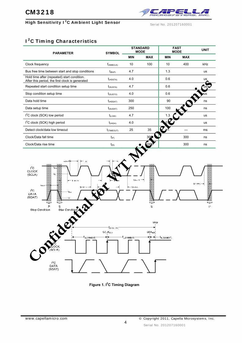
I2C Timing Characteristics
PARAMETER SYMBOLSTANDARD
MODE FAST MODE UNIT
MIN MAX MIN MAX
Clock frequency f(SMBCLK) 10 100 10 400 kHz
Bus free time between start and stop conditions t(BUF) 4.7 1.3 us
Hold time after (repeated) start condition. After this period, the first clock is generated t(HDSTA) 4.0 0.6 us
Repeated start condition setup time t(SUSTA) 4.7 0.6 us
Stop condition setup time t(SUSTO) 4.0 0.6 us
Data hold time t(HDDAT) 300 90 ns
Data setup time t(SUDAT) 250 100 ns
I2C clock (SCK) low period t(LOW) 4.7 1.3 us
I2C clock (SCK) high period t(HIGH) 4.0 0.6 us
Detect clock/data low timeout t(TIMEOUT) 25 35 --- --- ms
Clock/Data fall time t(F) 300 300 ns
Clock/Data rise time t(R) 1000 300 ns
Figure 1. I2C Timing Diagram
Confid
entia
l for W
T Micr
oelec
tronic
s

CM3218
High Sensitivity I2C Ambient Light Sensor
www.capellamicro.com © Copyright 2011, Capella Microsystems, Inc.
5
Serial No. 201207160001
Serial No. 201207160001
Parameter Timing Information
Figure 2-1. I2C Bus Timing for Sending Word Command Format
I2CBus CLOCK(SCLK)
I2CBus DATA
(SDAT) WSA6 SA5 SA4 SA3 SA2 SA1SA7
I2CBus Slave Address Byte
Start by Master
ACK byCM36292
SA6 SA5 SA4 SA3 SA2 SA0SA7
Command Code
SA1
ACK byCM36292
SA7 SA6 SA5 SA4 SA3 SA2 SA1 SA0
Stop byMaster
ACK byMaster
Data Byte High
I2CBus CLOCK(SCLK)
I2CBus DATA
(SDAT)
I2CBus CLOCK(SCLK)
I2CBus DATA
(SDAT) RSA6 SA5 SA4 SA3 SA2
I2CBus Slave Address Byte
Start by Master
ACK byCM36292
SA6 SA5 SA4 SA3 SA2 SA0SA7
Data Byte Low
SA1
ACK byMaster
SA1SA7
Figure 2-2. I2C Bus Timing for Receiving Word Command Format
Confid
entia
l for W
T Micr
oelec
tronic
s

CM3218
High Sensitivity I2C Ambient Light Sensor
www.capellamicro.com © Copyright 2011, Capella Microsystems, Inc.
6
Serial No. 201207160001
Serial No. 201207160001
Typical Performance Characteristics
Figure 3. Normalized Spectral Response
Figure 4. View Angle
Figure 5. IDD vs. Temperature Characteristics
Figure 6. RSET vs, Max Detection Range
Application Information
Confid
entia
l for W
T Micr
oelec
tronic
s

CM3218
High Sensitivity I2C Ambient Light Sensor
www.capellamicro.com © Copyright 2011, Capella Microsystems, Inc.
7
Serial No. 201207160001
Serial No. 201207160001
Pin Connection with the Host
CM3218 is a cost effective solution for an ambient light sensor with I2C interface. The standard serial digital interface easily accesses “light intensity” without using complex calculations and programming by an external controller. The additional capacitor near the VDD pin in the circuit is used for power supply noise rejection. The value is recommended at 0.1uF. The pull-high resistors for the I2C bus design are recommended to be 2.2KΩ. The RSET is recommended to be 604KΩ . An example of the circuit diagram is shown in Figure 7.
Figure 7. Hardware Pin Connection Diagram
Digital Interface
CM3218 I2C interface slave address is internally hardwired as CM3218A3OP: 0x10 and CM3218A3OP-AD: 0x48. CM3218 contains a command register written via the I2C bus. All operations can be controlled by the command register. The simple command structure allows the user to easily program the operation setting and latch the light data from CM3218. CM3218’s I2C command format description for Read and Write operations between CM3218 and the host is shown in Figure 8. The white areas indicate the host activity and the gray areas indicate CM3218’s acknowledgement of the host access activity.
Write Protocol -> Write Command to CM3218
Read Protocol -> Read data from CM3218
S = Start Condition P = Stop Condition A = Acknowledge
Figure 8. CM3218 Command Protocol
Confid
entia
l for W
T Micr
oelec
tronic
s
CM3218
High Sensitivity I2C Ambient Light Sensor
www.capellamicro.com © Copyright 2011, Capella Microsystems, Inc.
8
Serial No. 201207160001
Serial No. 201207160001
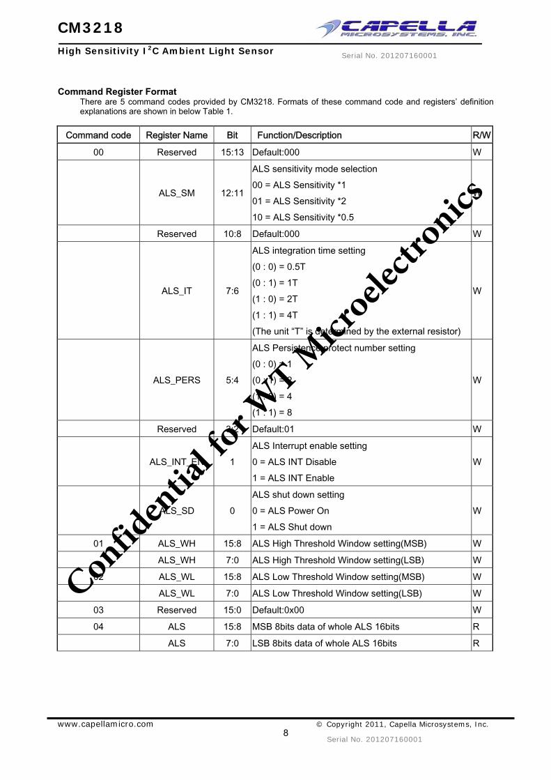
Command Register Format There are 5 command codes provided by CM3218. Formats of these command code and registers’ definition explanations are shown in below Table 1.
Command code Register Name Bit Function/Description R/W
00 Reserved 15:13 Default:000 W
ALS_SM 12:11
ALS sensitivity mode selection 00 = ALS Sensitivity *1 01 = ALS Sensitivity *2 10 = ALS Sensitivity *0.5
W
Reserved 10:8 Default:000 W
ALS_IT 7:6
ALS integration time setting (0 : 0) = 0.5T (0 : 1) = 1T (1 : 0) = 2T (1 : 1) = 4T (The unit “T” is determined by the external resistor)
W
ALS_PERS 5:4
ALS Persistence protect number setting (0 : 0) = 1 (0 : 1) = 2 (1 : 0) = 4 (1 : 1) = 8
W
Reserved 3:2 Default:01 W
ALS_INT_EN 1 ALS Interrupt enable setting 0 = ALS INT Disable 1 = ALS INT Enable
W
ALS_SD 0 ALS shut down setting 0 = ALS Power On 1 = ALS Shut down
W
01 ALS_WH 15:8 ALS High Threshold Window setting(MSB) W
ALS_WH 7:0 ALS High Threshold Window setting(LSB) W
02 ALS_WL 15:8 ALS Low Threshold Window setting(MSB) W
ALS_WL 7:0 ALS Low Threshold Window setting(LSB) W
03 Reserved 15:0 Default:0x00 W
04 ALS 15:8 MSB 8bits data of whole ALS 16bits R
ALS 7:0 LSB 8bits data of whole ALS 16bits R
Confid
entia
l for W
T Micr
oelec
tronic
s
CM3218
High Sensitivity I2C Ambient Light Sensor
www.capellamicro.com © Copyright 2011, Capella Microsystems, Inc.
9
Serial No. 201207160001
Serial No. 201207160001
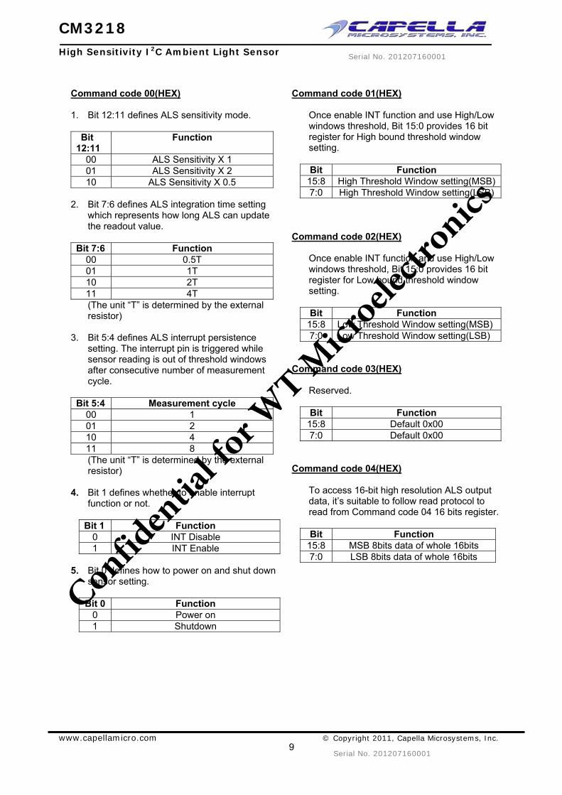
Command code 00(HEX) 1. Bit 12:11 defines ALS sensitivity mode.
Bit 12:11
Function
00 ALS Sensitivity X 1 01 ALS Sensitivity X 2 10 ALS Sensitivity X 0.5
2. Bit 7:6 defines ALS integration time setting
which represents how long ALS can update the readout value.
Bit 7:6 Function
00 0.5T 01 1T 10 2T 11 4T (The unit “T” is determined by the external resistor)
3. Bit 5:4 defines ALS interrupt persistence setting. The interrupt pin is triggered while sensor reading is out of threshold windows after consecutive number of measurement cycle.
Bit 5:4 Measurement cycle
00 1 01 2 10 4 11 8 (The unit “T” is determined by the external resistor)
4. Bit 1 defines whether to enable interrupt function or not.
Bit 1 Function
0 INT Disable 1 INT Enable
5. Bit 0 defines how to power on and shut down
sensor setting.
Bit 0 Function 0 Power on 1 Shutdown
Command code 01(HEX)
Once enable INT function and use High/Low windows threshold, Bit 15:0 provides 16 bit register for High bound threshold window setting.
Bit Function
15:8 High Threshold Window setting(MSB)7:0 High Threshold Window setting(LSB)
Command code 02(HEX)
Once enable INT function and use High/Low windows threshold, Bit 15:0 provides 16 bit register for Low bound threshold window setting.
Bit Function
15:8 Low Threshold Window setting(MSB)7:0 Low Threshold Window setting(LSB)
Command code 03(HEX)
Reserved.
Bit Function 15:8 Default 0x00 7:0 Default 0x00
Command code 04(HEX)
To access 16-bit high resolution ALS output data, it’s suitable to follow read protocol to read from Command code 04 16 bits register.
Bit Function
15:8 MSB 8bits data of whole 16bits 7:0 LSB 8bits data of whole 16bits
Confid
entia
l for W
T Micr
oelec
tronic
s

CM3218
High Sensitivity I2C Ambient Light Sensor
www.capellamicro.com © Copyright 2011, Capella Microsystems, Inc.
10
Serial No. 201207160001
Serial No. 201207160001
Interruption (INT) CM3218 has an ALS interrupt feature operated by a single pin “INT”. The purpose of the interrupt feature is to actively inform the host once the data is outside of threshold window. With the interrupt function applied, the host doesn’t need constantly pulling data from the sensor, but can just read data from the sensor while receiving interrupt request from the sensor. As long as the host implements the INT function, it read data and acknowledges Alert Response Address (ARA), 0x0C to disengage INT pin when INT is asserted. A command format for responding to an ARA is shown in Figure 9. If the data is 0x20 (CM3218-AD 0x90), then the INT is asserted by CM3218.
Figure 9. Command format for Responds to an ARA
Resolution to Ambient Light and Maximum Detection Range
CM3218 ambient light sensitivity can be tuned by an external resistor. To operate with the integration time (IT) setting, the light resolution (Lux/Step) is more precise and flexible. As the RSET value changes, the light resolution and the maximum detecting range also change. The correlation between RSET and the resolution (Lux/Step) is shown below:
SET1 SET2R * Resolution_1 = R * Resolution_2
Refresh Time Determination
CM3218’s refresh time can be determined by the RSET value. Cooperating with the command register setting, the designer has a flexible method in defining the timing for light data collection. The default refresh time is 1T, ALS_IT = (0 : 1). If the RSET value is changed, the default timing changes and other parts in the register table also change relative to the default timing. An example of two RSET resistors that show the timing table in which the system designer can determine the desired refresh time flexibly is shown in Table 2.
REGISTER SETTING REFRESH TIME TABLE
RSET = 604KΩ
ALS_IT
(0 : 0) = ½T 125ms (0 : 1) = 1T 250ms (1 : 0) = 2T 500ms (1 : 1) = 4T 1000ms
Table 2. Example of Refresh Time and RSET Value Relation Table If CM3218’s refresh time is required to be at 500ms, the calculation of the refresh time becomes:
1). If RSET = 604KΩ, “IT” register value should set to (1:0), 2T. 2). If RSET = 300KΩ, “IT” register value should set to (1:1), 4T.
The parameter is independent from other command register settings. The designer can obtain the refresh timing range of the system operation requirement first, choose an appropriate RSET value for the timing range setting and then write the correct value for the system application via I2C protocol.
Auto-Memorization
CM3218 can memorize the last ambient light data before shutdown and keep this data before waking up. When CM3218 is in shutdown mode, the host can freely read this data via Read command directly. When CM3218 wakes up, the data will be refreshed by the new detection.
Confid
entia
l for W
T Micr
oelec
tronic
s

CM3218
High Sensitivity I2C Ambient Light Sensor
www.capellamicro.com © Copyright 2011, Capella Microsystems, Inc.
11
Serial No. 201207160001
Serial No. 201207160001
Package Information
Pin 1 Marking
0.44
1.0
±0.
1
CM3218 Pin-out assignment
1
5
43
2
6
SET
VDD
SCLK
GND
INT
SDAT
Unit: mm
1
3 4
6
TOP VIEW BOTTOM VIEWSIDE VIEW
0 ~ 0.08
0 ~ 0.08
0.45 ± 0.1
2.35 ± 0.15
1.80
±0.
15
0.6
0.3
±0.
1
0.07
50.
3 ±
0.1
0.15
1.35
0.03 ~ 0.11
0.9±
0.1
0.78
±0.1
PD center
1.18 ± 0.1
1.16 ± 0.1
Figure 10. CM3218 A3OP Package Dimensions
Figure 11. CM3218 OPLGA PCB Layout Footprint
Confid
entia
l for W
T Micr
oelec
tronic
s

CM3218
High Sensitivity I2C Ambient Light Sensor
www.capellamicro.com © Copyright 2011, Capella Microsystems, Inc.
12
Serial No. 201207160001
Serial No. 201207160001
Recommended Storage and Rebaking Conditions PARAMETER MIN MAX UNITS CONDITION
Storage temperature 5 50 °C
Relative humidity 60 %
Open time 168 hrs
Total time 6 months from the date code on the aluminized envelope (unopened)
Rebaking 1. Tape and Reel: 60 ºC , 22 hours 2. Tube: 60 ºC , 22 hours
Recommended Infrared Reflow Soldering conditions are based on J-STD-020 C definition.
1. IR reflow profile conditions
PARAMETER TEMPERATURE TIME CONDITION
Peak temperature 255+0/-5 ºC (Max: 260 ºC) 10 seconds
Preheat temperature range and timing 150 ~ 200 ºC 60 ~ 180 seconds
Timing within 5 ºC to peak temperature 10 ~ 30 seconds
Timing maintained above temperature / time 217 ºC 60 ~ 150 seconds
Timing from 25 ºC to peak temperature 8 minutes (Max)
Ramp-up rate 3 ºC / seconds (Max)
Ramp-down rate 6 ºC / seconds (Max)
2. Recommended normal solder reflow is: 235 ~ 255 .
Tem
pera
ture
(ºC
)
Figure 12. CM3218 Solder Reflow Profile Chart
Confid
entia
l for W
T Micr
oelec
tronic
s

CM3218
High Sensitivity I2C Ambient Light Sensor
www.capellamicro.com © Copyright 2011, Capella Microsystems, Inc.
13
Serial No. 201207160001
Serial No. 201207160001
Recommended Iron Tip Soldering Condition and Warning Handling 1 Solder the device with the following conditions:
1.1 Soldering temperature: 400 (Max.) 1.2 Soldering time: 3 seconds (Max.)
2 If the temperature of the method portion rises in addition to the residual stress between the leads, the possibility that open or short circuit occurs due to the deformation or destruction of the resin increases.
3 The following methods: VPS, and wave soldering are not suggested for the component assembly. 4 Cleaning method condition:
4.1 Solvent: Methyl Alcohol, Ethyl Alcohol, and Isopropyl Alcohol. 4.2 Solvent temperature < 45 (Max.); 4.3 Time: 3 minutes (Min.)
Confid
entia
l for W
T Micr
oelec
tronic
s

CM3218
High Sensitivity I2C Ambient Light Sensor
www.capellamicro.com © Copyright 2011, Capella Microsystems, Inc.
14
Serial No. 201207160001
Serial No. 201207160001
Packing Information
12.0
0 +0
.30
/ -0.
10
0.28
±0.
02
1.75
±0.
10
5.50
±0.
10
1.25
±0.
10
Figure 13. CM3218 A3OP Package Carrier Tape
Figure 14. Taping Direction
Figure 15. Reel Dimension
CAPELLA MICROSYSTEMS, INC Taiwan office USA office 6F, No.43, Fusing Road, Sindian City, Taipei County 231, Taiwan 2361 Calle Del Mundo, Santa Clara, CA95054 TEL: +886-2-82186600 TEL: 408-727-8500 FAX: +886-2-82186602 FAX: 408-969-0894
Confid
entia
l for W
T Micr
oelec
tronic
s