SERAIR 435DM55147 V22 Vehicle Reqts Released
7
DEPARTMENT OF THE NAVY NAVAL AIR WARFARE CENTER, AIRCRAFT DIVISION 48110 Shaw Road, Building 2187, Unit 5, Patuxent River, Maryland 20670-1906 SERAIR 435DM/5.5147 9 April 2008 MEMORANDUM FOR RECORD From: Naval Air Systems Command, Douglas Mousseau, AIR-4.3.5.4, 48110 Shaw Road, Building 2187, Lab 1B10, Patuxent River, Maryland 20670-1906 Subj: Transportability of wheeled vehicle systems in the V-22 (Released) The purpose of the document is to provide a brief summary of experience from AIR – 4.3.5.4’s Cargo and Special Ops Competency transportability assessments for wheeled vehicle systems in the V-22. The results from these assessments can aid in the development of future vehicle systems that are considered for transport in the V-22 aircraft. For further assistance please contact Doug Mousseau, Code 4.3.5.4, Cargo/Special Operations at 301-342-1009, [email protected] or Todd Anderson, Code 4.3.5.4, Cargo/Special Operations at 301-995-3173, [email protected]. Douglas J Mousseau Cargo, Special Operations
Transcript of SERAIR 435DM55147 V22 Vehicle Reqts Released
DEPARTMENT OF THE NAVY NAVAL AIR WARFARE CENTER, AIRCRAFT DIVISION
48110 Shaw Road, Building 2187, Unit 5, Patuxent River, Maryland 20670-1906
SERAIR 435DM/5.5147 9 April 2008
MEMORANDUM FOR RECORD From: Naval Air Systems Command, Douglas Mousseau, AIR-4.3.5.4, 48110 Shaw Road,
Building 2187, Lab 1B10, Patuxent River, Maryland 20670-1906 Subj: Transportability of wheeled vehicle systems in the V-22 (Released)
The purpose of the document is to provide a brief summary of experience from AIR – 4.3.5.4’s Cargo and Special Ops Competency transportability assessments for wheeled vehicle systems in the V-22. The results from these assessments can aid in the development of future vehicle systems that are considered for transport in the V-22 aircraft.
For further assistance please contact Doug Mousseau, Code 4.3.5.4, Cargo/Special Operations at 301-342-1009, [email protected] or Todd Anderson, Code 4.3.5.4, Cargo/Special Operations at 301-995-3173, [email protected].
Douglas J Mousseau Cargo, Special Operations
Page 1
1.0 PURPOSE OF DOCUMENT
The purpose of this document is to provide guidance relating to internal air transport of vehicles and other wheeled cargo in the V-22. The information covered in this document is not all encompassing, as there are many design considerations that must be taken into account in addition to those shown in order to safely load, secure and fly wheeled cargo in the V-22. 2.0 DESIGN CONSIDERATIONS
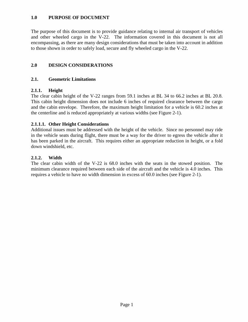
2.1. Geometric Limitations 2.1.1. Height The clear cabin height of the V-22 ranges from 59.1 inches at BL 34 to 66.2 inches at BL 20.8. This cabin height dimension does not include 6 inches of required clearance between the cargo and the cabin envelope. Therefore, the maximum height limitation for a vehicle is 60.2 inches at the centerline and is reduced appropriately at various widths (see Figure 2-1). 2.1.1.1. Other Height Considerations Additional issues must be addressed with the height of the vehicle. Since no personnel may ride in the vehicle seats during flight, there must be a way for the driver to egress the vehicle after it has been parked in the aircraft. This requires either an appropriate reduction in height, or a fold down windshield, etc. 2.1.2. Width The clear cabin width of the V-22 is 68.0 inches with the seats in the stowed position. The minimum clearance required between each side of the aircraft and the vehicle is 4.0 inches. This requires a vehicle to have no width dimension in excess of 60.0 inches (see Figure 2-1).
Page 2
Figure 2-1: V-22 Cabin Envelope
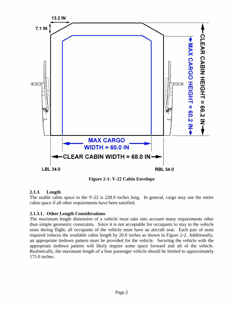
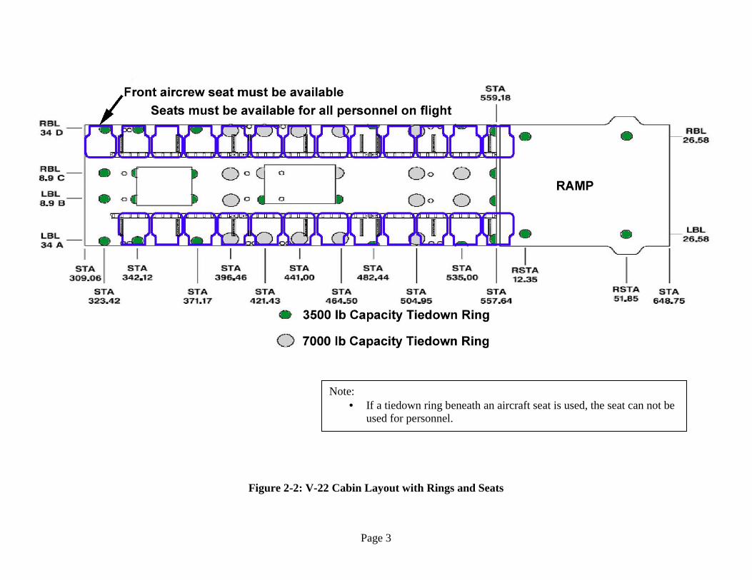
2.1.3. Length The usable cabin space in the V-22 is 228.9 inches long. In general, cargo may use the entire cabin space if all other requirements have been satisfied. 2.1.3.1. Other Length Considerations The maximum length dimension of a vehicle must take into account many requirements other than simple geometric constraints. Since it is not acceptable for occupants to stay in the vehicle seats during flight, all occupants of the vehicle must have an aircraft seat. Each pair of seats required reduces the available cabin length by 20.0 inches as shown in Figure 2-2. Additionally, an appropriate tiedown pattern must be provided for the vehicle. Securing the vehicle with the appropriate tiedown pattern will likely require some space forward and aft of the vehicle. Realistically, the maximum length of a four passenger vehicle should be limited to approximately 175.0 inches.
Page 3
Figure 2-2: V-22 Cabin Layout with Rings and Seats
Note: • If a tiedown ring beneath an aircraft seat is used, the seat can not be
used for personnel.
Page 4
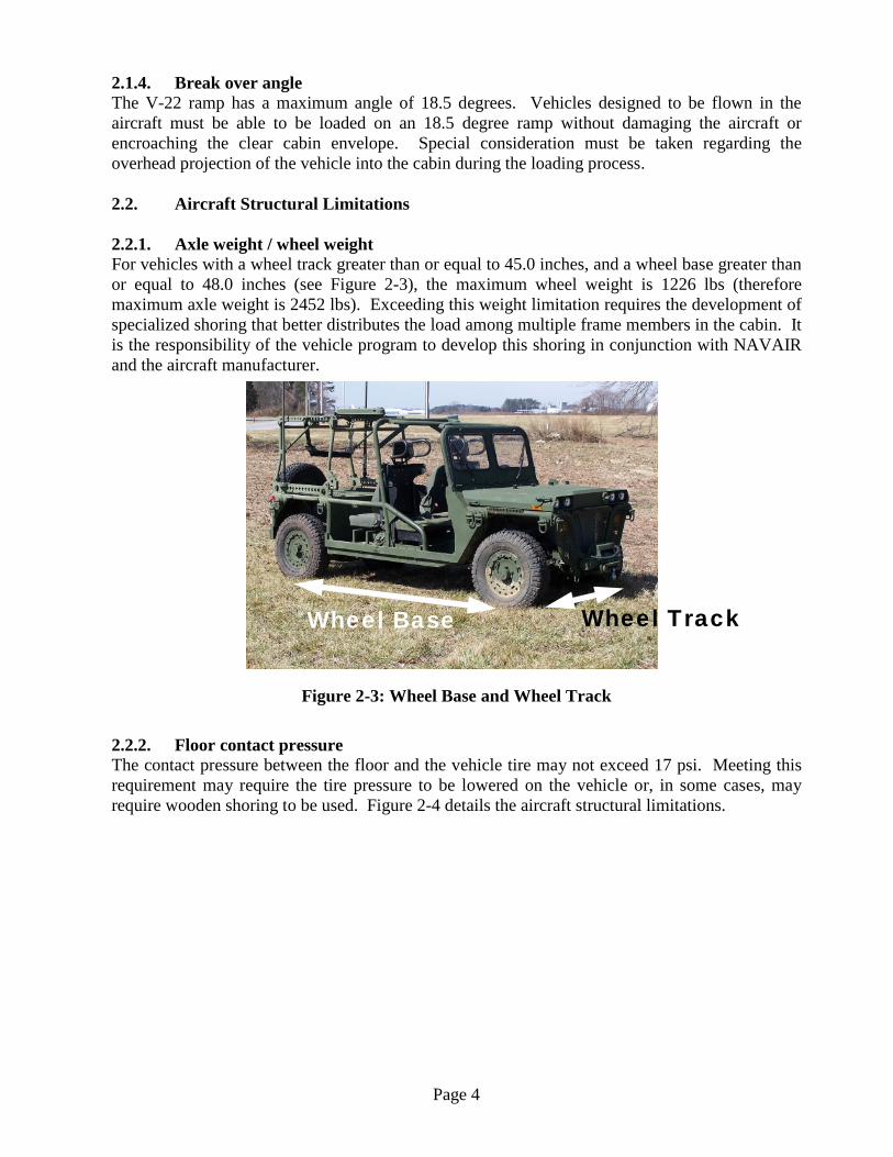
2.1.4. Break over angle The V-22 ramp has a maximum angle of 18.5 degrees. Vehicles designed to be flown in the aircraft must be able to be loaded on an 18.5 degree ramp without damaging the aircraft or encroaching the clear cabin envelope. Special consideration must be taken regarding the overhead projection of the vehicle into the cabin during the loading process. 2.2. Aircraft Structural Limitations 2.2.1. Axle weight / wheel weight For vehicles with a wheel track greater than or equal to 45.0 inches, and a wheel base greater than or equal to 48.0 inches (see Figure 2-3), the maximum wheel weight is 1226 lbs (therefore maximum axle weight is 2452 lbs). Exceeding this weight limitation requires the development of specialized shoring that better distributes the load among multiple frame members in the cabin. It is the responsibility of the vehicle program to develop this shoring in conjunction with NAVAIR and the aircraft manufacturer.
Figure 2-3: Wheel Base and Wheel Track
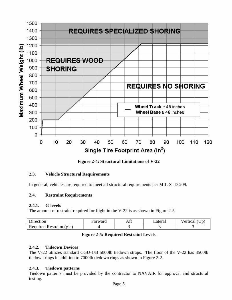
2.2.2. Floor contact pressure The contact pressure between the floor and the vehicle tire may not exceed 17 psi. Meeting this requirement may require the tire pressure to be lowered on the vehicle or, in some cases, may require wooden shoring to be used. Figure 2-4 details the aircraft structural limitations.
Wheel Base Wheel Track
Page 5
Figure 2-4: Structural Limitations of V-22
2.3. Vehicle Structural Requirements In general, vehicles are required to meet all structural requirements per MIL-STD-209. 2.4. Restraint Requirements 2.4.1. G-levels The amount of restraint required for flight in the V-22 is as shown in Figure 2-5. Direction Forward Aft Lateral Vertical (Up) Required Restraint (g’s) 4 3 3 3
Figure 2-5: Required Restraint Levels 2.4.2. Tideown Devices The V-22 utilizes standard CGU-1/B 5000lb tiedown straps. The floor of the V-22 has 3500lb tiedown rings in addition to 7000lb tiedown rings as shown in Figure 2-2. 2.4.3. Tiedown patterns Tiedown patterns must be provided by the contractor to NAVAIR for approval and structural testing.
Page 6
3.0 POINTS OF CONTACT
NAVAIR Cargo and Special Operations Team: Doug Mousseau – Primary POC for vehicle transport and general internal cargo questions [email protected] 301-342-1009 (w) Todd Anderson – Primary POC for general internal cargo and special operations questions [email protected] 301-995-3173 (w) 240-538-6012 (c) Jon Wiedorn – Primary POC for all external cargo questions [email protected] 732-323-2578 (w) 4.0 REFERENCES
• MIL-STD-209 – Interface Standard for Lifting and Tiedown Provisions. Available
electronically from: http://assist.daps.dla.mil/quicksearch/ • MIL-STD-1366 – Interface Standard for Transportability Criteria. Available
electronically from: http://assist.daps.dla.mil/quicksearch/ • NAVSUP PUB 505 – Preparing Hazardous Materials for Military Air Shipments.
Available electronically (as Air Force Manual 24-204) from: http://www.e-publishing.af.mil/