Sequential Circuit Design
30
MOHD. YAMANI IDRIS/ NOORZAILY MOHAMED NOOR 1 Sequential Circuit Design
-
Upload
caesar-browning -
Category
Documents
-
view
73 -
download
2
description
Sequential Circuit Design. Sequential Logic Design. Contents Why sequential logic? Flip-flop criteria table Sequential circuit analysis Sequential circuit design. Why Sequential Logic?. Sequential circuit has additional dimension which is time - PowerPoint PPT Presentation
Transcript of Sequential Circuit Design

MOHD. YAMANI IDRIS/ NOORZAILY MOHAMED NOOR
1
Sequential Circuit Design

MOHD. YAMANI IDRIS/ NOORZAILY MOHAMED NOOR
2
Sequential Logic Design
Contents Why sequential logic? Flip-flop criteria table Sequential circuit analysis Sequential circuit design

MOHD. YAMANI IDRIS/ NOORZAILY MOHAMED NOOR
3
Why Sequential Logic?
Sequential circuit has additional dimension which is time
Combinational logic only depends on current input
Sequential circuit output depends on previous input other than current input
More powerful than combination logic Able to model condition which can’t be modeled
by combinational logic

MOHD. YAMANI IDRIS/ NOORZAILY MOHAMED NOOR
4
Sequential Circuit Analysis
Given sequential circuit diagram, behavioral analysis from state table and also state diagram
Need state equations to get flip-flop input and output functions for circuit output other than flip-flop (if any)
We use A(t) and A(t+1) to represent current condition and the next condition for flip-flop represented by A.
Other method, we can use A and A+ to represent current condition and the following condition

MOHD. YAMANI IDRIS/ NOORZAILY MOHAMED NOOR
5
Sequential Circuit Analysis Example 1 (using D flip-flop)
State equation
Output Function

MOHD. YAMANI IDRIS/ NOORZAILY MOHAMED NOOR
6
Sequential Circuit Analysis
From the state equations and output function, we can derive state table which contains all combined binary available for current condition and input
State table The same as Truth Table Input and condition pad on the left Output and next condition on the right combined binary available for current condition and input
M flip-flop and n input => 2m+n line

MOHD. YAMANI IDRIS/ NOORZAILY MOHAMED NOOR
7
Sequential Circuit AnalysisState equation Output function
State table for circuit in Example 1

MOHD. YAMANI IDRIS/ NOORZAILY MOHAMED NOOR
8
Sequential Circuit Analysis
Other method

MOHD. YAMANI IDRIS/ NOORZAILY MOHAMED NOOR
9
Sequential Circuit Analysis
From the truth table, we can draw state diagram State diagram
Each state is represented by circle Each arrow (between two circle) represent transfer for
sequential logic (i.e. line transition in truth table) a/b label for each arrow where a represent inputs and
b represent output for circuit in transition Each flip-flop value combination represent state.
Therefore, m flip-flop=> until 2m state.

MOHD. YAMANI IDRIS/ NOORZAILY MOHAMED NOOR
10
Sequential Circuit Analysis
State diagram for circuit in example 1

MOHD. YAMANI IDRIS/ NOORZAILY MOHAMED NOOR
11
Flip-flop Input Function Output of sequential circuit is function for
current condition for flip-flop and input. This is explained using algebra by circuit output function In example 1: y= (A+B)x’
Circuit part that generate input to flip-flop is explained using algebra by flip-flop input functions

MOHD. YAMANI IDRIS/ NOORZAILY MOHAMED NOOR
12
Flip-flop Input Function Flip-flop input function determine next
condition From flip-flop input function and criteria table
for flip-flop, we get next condition of the flip-flop

MOHD. YAMANI IDRIS/ NOORZAILY MOHAMED NOOR
13
Flip-flop Input Function
Example 2: circuit with JK flip flop We use 2 character to represent flip-flop input:
first character represent flip-flop input (J or K for JK flip-flop, S or R for SR flip-flop, D for D flip-flop, T for T flip-flop ) and second character represent name of the flip-flop

MOHD. YAMANI IDRIS/ NOORZAILY MOHAMED NOOR
14
Analysis: Example 3 Given sequential circuit with two JK flip-flop, A
and B and one input x
Get the input flip-flop function from the circuit

MOHD. YAMANI IDRIS/ NOORZAILY MOHAMED NOOR
15
Analysis: Example 3 Input flip-flop function
Fill the state table with the above function using criteria table for used flip-flop

MOHD. YAMANI IDRIS/ NOORZAILY MOHAMED NOOR
16
Analysis: Example 3 Draw state diagram from the state table
MOHD. YAMANI IDRIS/ NOORZAILY MOHAMED NOOR
17
Flip-flop Excitation Tables Analysis: Start from circuit diagram, build state table
or state diagram Design: Start from specification set (i.e. in state
equation form, state table or state diagram) build logic circuit.
Criteria table is used in analysis Excitation tables is used in design

MOHD. YAMANI IDRIS/ NOORZAILY MOHAMED NOOR
18
Flip-flop Excitation Tables Excitation tables : it give transition characteristic
between current condition and next condition to determine flip-flop input

MOHD. YAMANI IDRIS/ NOORZAILY MOHAMED NOOR
19
Designing Sequential CircuitDesign steps Start with circuit spesification – characteristic of circuit Build state table Do state reduction if needed (not in syllabus) Do state assignment (not in syllabus) Determine number of flip-flop which will be used Build circuit excitation and output table from state table Build circuit output function and flip-flop input function Draw logic diagram

MOHD. YAMANI IDRIS/ NOORZAILY MOHAMED NOOR
20
Design: Example 1 Given state diagram as follows, get the sequential
circuit using JK flip-flop
MOHD. YAMANI IDRIS/ NOORZAILY MOHAMED NOOR
21
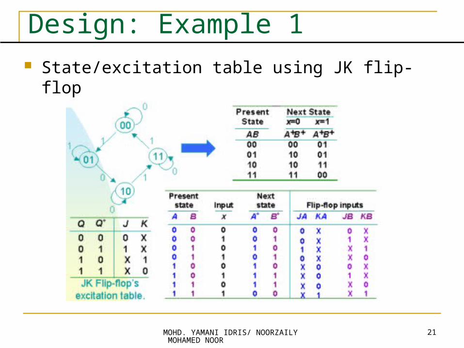
Design: Example 1 State/excitation table using JK flip-flop

MOHD. YAMANI IDRIS/ NOORZAILY MOHAMED NOOR
22
Design: Example 1 Block diagram

MOHD. YAMANI IDRIS/ NOORZAILY MOHAMED NOOR
23
Design: Example 1 From state table, get input flip-flop function

MOHD. YAMANI IDRIS/ NOORZAILY MOHAMED NOOR
24
Design: Example 1 Input flip-flop function
Logic Diagram

MOHD. YAMANI IDRIS/ NOORZAILY MOHAMED NOOR
25
Design: Example 2 Design, using D flip-flop, circuit is based on state
table below. (Exercise: How if using JK flip-flop)

MOHD. YAMANI IDRIS/ NOORZAILY MOHAMED NOOR
26
Design: Example 2 Determine input expression for flip-flop and y
output

MOHD. YAMANI IDRIS/ NOORZAILY MOHAMED NOOR
27
Design: Example 2 From expression built, draw logic diagram

MOHD. YAMANI IDRIS/ NOORZAILY MOHAMED NOOR
28
Design a Synchronous Counter Counter: sequential circuit cycle through state sequence Binary counter: follow binary sequence. n-bit binary
counter (with n flip-flop) able to count from 0 to 2n-1. Example 1: 3-bit binary counter (using T flip-flop)

MOHD. YAMANI IDRIS/ NOORZAILY MOHAMED NOOR
29
Design a Synchronous Counter 3-bit binary counter (cont)

MOHD. YAMANI IDRIS/ NOORZAILY MOHAMED NOOR
30
Design a Synchronous Counter 3-bit binary counter (cont)