Sequence Stratigraphy of Akos Field in the Coastal … online a t elagia esearch ibrary Adances in...
12
Available online at www.pelagiaresearchlibrary.com Pelagia Research Library Advances in Applied Science Research, 2017, 8(1):16-27 ISSN : 0976-8610 CODEN (USA): AASRFC Pelagia Research Library 16 Sequence Stratigraphy of Akos Field in the Coastal Swamp Depobelt of the Niger Delta Tope S Alege* Department of Earth Sciences, Kogi State University, Anyigba, Nigeria ABSTRACT Well-log sequence stratigraphy has been carried out in the Akos field aimed at studying its stratigraphic framework. Four major sequence boundaries dated back at 12.1 Ma, 10.6 Ma, 10.35 Ma and 8.5 Ma and three intervening Maximum Flooding Surfaces (MFS) 11.5 Ma, 10.4Ma and 9.5Ma have been respectively identified. They are denoted as Dodo shale, Nonion-4 and Uvigerina-8 markers falling within the Central Swamp depobelt of the Niger Delta. Three depositional sequences (sequence 1, 2 and 3) have been delineated, whereas sequence-1 is an incomplete sequence in most of the wells. In the wells 007, 009 and 013, it is completely lacking. Three major parasequence stacking patterns; progradational, retrogradational and aggradational as well as four systems tracts namely: Lowstand Systems Tract (LST), Transgressive Systems Tract (TST), Highstand Systems Tract (HST) and the Falling Stage Systems Tract (FSST) have been interpreted. The alternation of the reservoir sands of the LST and HST and the shale units of the TST offers excellent stratigraphic traps for hydrocarbon. Keywords: Stratigraphic sequence, Niger Delta, Para sequence, Stratigraphic traps, Hydrocarbons INTRODUCTION Over 80% of Nigeria’s revenue comes from oil and gas, with the Niger Delta basin as the main target. The Niger Delta Province contains only one identified petroleum system [1] referred to as the Tertiary Niger Delta (Akata–Agbada) Petroleum System. Currently, most of this petroleum are in fields that are onshore or on the continental shelf (in waters less than 200 meters deep), and occurs primarily in geological structures such as rollover anticlines and faults. A few large oil fields are present in the Delta; the largest contains just over 1.0 BBO. Among the provinces ranked in the U.S. Geological Survey's World Energy Assessment [2], the Niger Delta province is the twelfth richest in petroleum resources, with 2.2% of the world’s discovered oil and 1.4% of the world’s discovered gas [3]. It was necessary to improve the existing geological knowledge of the Niger Delta region through the application of modern concepts of sequence stratigraphy in a bid to satisfy the increasing demand for production of the vast hydrocarbon resources. The growing call for hydrocarbon prospecting, however, justifies the use of the concept of sequence stratigraphy to develop the framework and stratigraphic play concepts of Akos Field. GEOLOGICAL SETTING This study was conducted in an oil field situated in the onshore part of the Coastal Swamp Depobelt of the Niger Delta (Figure 1). The original name of the field is kept confidential owing to the proprietary nature of the concession. The name Akos field given to it is arbitrary. From the Eocene to the present times, the delta prograded southwestwards, forming depobelts representing the most active portion of the delta at each stage of its development [4]. In the region of the Niger Delta, rifting diminished altogether in the Late Cretaceous [5]. After rifting ceased, gravity tectonism became the primary deformational process.
Transcript of Sequence Stratigraphy of Akos Field in the Coastal … online a t elagia esearch ibrary Adances in...
Available online at www.pelagiaresearchlibrary.com
Pelagia Research Library
Advances in Applied Science Research, 2017, 8(1):16-27
ISSN : 0976-8610CODEN (USA): AASRFC
Pelagia Research Library16
Sequence Stratigraphy of Akos Field in the Coastal Swamp Depobelt of the Niger Delta
Tope S Alege*Department of Earth Sciences, Kogi State University, Anyigba, Nigeria
ABSTRACT
Well-log sequence stratigraphy has been carried out in the Akos field aimed at studying its stratigraphic framework. Four major sequence boundaries dated back at 12.1 Ma, 10.6 Ma, 10.35 Ma and 8.5 Ma and three intervening Maximum Flooding Surfaces (MFS) 11.5 Ma, 10.4Ma and 9.5Ma have been respectively identified. They are denoted as Dodo shale, Nonion-4 and Uvigerina-8 markers falling within the Central Swamp depobelt of the Niger Delta. Three depositional sequences (sequence 1, 2 and 3) have been delineated, whereas sequence-1 is an incomplete sequence in most of the wells. In the wells 007, 009 and 013, it is completely lacking. Three major parasequence stacking patterns; progradational, retrogradational and aggradational as well as four systems tracts namely: Lowstand Systems Tract (LST), Transgressive Systems Tract (TST), Highstand Systems Tract (HST) and the Falling Stage Systems Tract (FSST) have been interpreted. The alternation of the reservoir sands of the LST and HST and the shale units of the TST offers excellent stratigraphic traps for hydrocarbon.
Keywords: Stratigraphic sequence, Niger Delta, Para sequence, Stratigraphic traps, Hydrocarbons
INTRODUCTION
Over 80% of Nigeria’s revenue comes from oil and gas, with the Niger Delta basin as the main target. The Niger Delta Province contains only one identified petroleum system [1] referred to as the Tertiary Niger Delta (Akata–Agbada) Petroleum System. Currently, most of this petroleum are in fields that are onshore or on the continental shelf (in waters less than 200 meters deep), and occurs primarily in geological structures such as rollover anticlines and faults. A few large oil fields are present in the Delta; the largest contains just over 1.0 BBO. Among the provinces ranked in the U.S. Geological Survey's World Energy Assessment [2], the Niger Delta province is the twelfth richest in petroleum resources, with 2.2% of the world’s discovered oil and 1.4% of the world’s discovered gas [3].
It was necessary to improve the existing geological knowledge of the Niger Delta region through the application of modern concepts of sequence stratigraphy in a bid to satisfy the increasing demand for production of the vast hydrocarbon resources. The growing call for hydrocarbon prospecting, however, justifies the use of the concept of sequence stratigraphy to develop the framework and stratigraphic play concepts of Akos Field.
GEOLOGICAL SETTING
This study was conducted in an oil field situated in the onshore part of the Coastal Swamp Depobelt of the Niger Delta (Figure 1). The original name of the field is kept confidential owing to the proprietary nature of the concession. The name Akos field given to it is arbitrary.
From the Eocene to the present times, the delta prograded southwestwards, forming depobelts representing the most active portion of the delta at each stage of its development [4]. In the region of the Niger Delta, rifting diminished altogether in the Late Cretaceous [5]. After rifting ceased, gravity tectonism became the primary deformational process.

Alege AdvAppl Sci Res., 2017, 8(1):16-27
Pelagia Research Library17
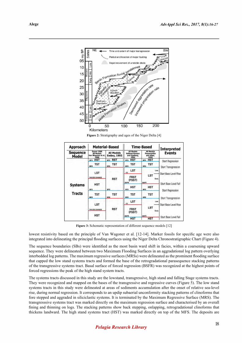
Shale mobility induced internal deformation and occurred in response to two processes [6]. First, shale diapers formed from loading of poorly compacted, over-pressured, prodelta and delta-slope clays (Akata Formation.) by the higher density delta-front sands (Agbada Formation). Second, slope instability occurred due to lack of lateral, basinward, support for the under-compacted delta-slope clays (Akata Formation). For any given depobelt, gravity tectonics were completed before deposition of the Benin Formation and are expressed in complex structures, including shale diapers, roll-over anticlines, collapsed growth fault crest, back-to-back features, and steeply dipping, closely spaced flank faults. The structural development of the Niger Delta was controlled by differential loading of the underlying prodelta shales of the deltaic succession. The deformational pattern gave rise to a series of parallel belts (depobelts or mega-structures) that exihibit common characteristics relating to charge and hydrocarbon occurrence [7]. Three lithostratigraphic units have been recognized in the subsurface of the Niger Delta; the Akata, Agbada and Benin Formations all of which are strongly diachronous (Figure 2) [8].
MATERIALS AND METHODS
The study focuses on the analysis of seven well logs for the interpretation of sequence stratigraphic framework of the Akos Field within the coastal swamp depobelt of the Niger Delta Basin.
Well log analysis
Seven wells consisting of gamma ray and resistivity logs were used for lithologic identification. The general procedure of sequence stratigraphic analysis was adopted from Vail and Wonardt. The first approach involved delineation of the different lithologies and the parasequence stacking patterns using the gamma ray log signatures. In distinguishing between shale and sand, the gamma ray log used in this study has a shale reference line of 75 American Petroleum Institute (API), chosen from the range of 0–150 API values which responded to the natural radioactivity of the formation. Sandy lithologies were painted yellow, while shaly lithologies were painted grey. These analyses were carried out with the aid of Petrel software by Schlumberger.
Key surfaces (Maximum Flooding Surfaces, Maximum Regressive Surfaces, Basal Surface of Forced Regression (BSFR), and Sequence Boundaries) were identified to subdivide the stratigraphic column into depositional sequences and systems tracts. The approach employed for defining key stratigraphic surfaces and systems tracts were based on Depositional (IV) model in Figure 3 [9-11].
Recognition of stratigraphic surfaces and systems tracts on well logs
The maximum flooding surfaces were recognized by identifying points with the highest Gamma ray response and
Figure 1: Schematic play map showing the location of Akos Field in relation to depobelts (Courtesy: DPR)
Alege AdvAppl Sci Res., 2017, 8(1):16-27
Pelagia Research Library18
lowest resistivity based on the principle of Van Wagoner et al. [12-14]. Marker fossils for specific age were also integrated into delineating the principal flooding surfaces using the Niger Delta Chronostratigraphic Chart (Figure 4).
The sequence boundaries (SBs) were identified as the most basin ward shift in facies, within a coarsening upward sequence. They were delineated between two Maximum Flooding Surfaces in an aggradational log pattern overlying interbedded log patterns. The maximum regressive surfaces (MRSs) were delineated as the prominent flooding surface that capped the low stand systems tracts and formed the base of the retrogradational parasequence stacking patterns of the transgressive systems tract. Basal surface of forced regression (BSFR) was recognized at the highest points of forced regressions the peak of the high stand system tracts.
The systems tracts discussed in this study are the lowstand, transgressive, high stand and falling Stage systems tracts. They were recognized and mapped on the bases of the transgressive and regressive curves (Figure 5). The low stand systems tracts in this study were delineated at areas of sediments accumulation after the onset of relative sea-level rise, during normal regression. It corresponds to an updip subaerial unconformity stacking patterns of clinoforms that fore stepped and aggraded in siliciclastic systems. It is terminated by the Maximum Regressive Surface (MRS). The transgresssive systems tract was marked directly on the maximum regression surface and characterised by an overall fining and thinning on logs. The stacking patterns show back stepping, onlapping, retrogradational clinoforms that thickens landward. The high stand systems tract (HST) was marked directly on top of the MFS. The deposits are
Figure 2: Stratigraphy and ages of the Niger Delta [4]
Figure 3: Schematic representation of different sequence models [12]

Alege AdvAppl Sci Res., 2017, 8(1):16-27
Pelagia Research Library19
Figure 4: Niger Delta cenozoic chronostratigraphic chart [13] Source: SPDC
Figure 5: Sequences, systems tracts and stratigraphic surfaces defined in relation to the base-level and the transgressive–regressive curves [15]
prograding and aggrading and terminated at the basal surface of forced regression. Falling stage systems tract (FSST) is a unit of a sequence defined by a basal surface of forced regression (BSFR) at the lower boundary and a sequence boundary as the upper boundary. The FSST is a time-based systems tract that is formed by forced regressive deposits that accumulated after the onset of a relative sea-level fall and before the start of the next relative sea-level rise [15-17].

Alege AdvAppl Sci Res., 2017, 8(1):16-27
Pelagia Research Library20
RESULTS
Akos Well 001 and 012st1
These wells terminated at a depth of 1150ft and were correlated along the same strike section and display little disparities in the position of well tops (Figure 6). The sequence stratigraphic framework of wells 001 and 012st1 are displayed in Figures 7 and 8, respectively.
Sequence 1 is an incomplete sequence that started with the transgressive systems tracts at a depth of 11200ft with diagnostic retrogradational stacking patterns resulting in overall fining upward profiles that are capped by the 11.5Ma Dodo shale maximum flooding surface associated with a major condensed section at a depth of 10680ft. The high stand systems tracts capped the TST-1 with some aggrading units and subsequently begin to display a progradational stacking pattern. It is truncated by a sudden gradual decrease in baselevel resulting in the high stand stratal termination at the basal surface of forced regression (BSFR) (9650ft) giving room to the falling stage systems tract (FSST) emergence. The falling stage systems tracts capped this sequence at the 10.6Ma sequence boundary on the depth of 9350ft.
Sequence 2 commenced with the low stand systems tract which ranged from 9350ft to 7300ft with a prograding fan complex characterised by a general trend of coarsening upward; shore face sand bodies that prograded into hemipelagic shales. The maximum regressive surface capped this systems tract at depth 7300 ft. The transgressive systems tract overlies the maximum regressive surface with a characteristic retrogradational stacking pattern culminating in the transgressive peak at the 10.4 Ma Nonion-4 MFS at a depth of 7800 ft. The highstand systems tract extended from the top of the maximum flooding surface to terminate at the basal surface of forced regression (BSFR) at 7450 ft. This commenced the deposits of the falling stage systems tract that terminated at the 10.35 Ma sequence boundary.
Sequence 3 covered a total depth of 3650ft and began with a lower sequence boundary at 7450 ft. The sequence is initiated by the low stand systems tract as it is marked by a characteristic log motif typical of coarsening upward back stepping aggradational stacking pattern that ended at the maximum regressive surface (MRS) (Figures 6-8). The LST is overlain by a short episode of deposition of the transgressive systems tract initiated at 6550 ft and capped by the maximum flooding surface depicted by the Uvigerina-8 marker at 6800 ft. The High stand Systems Tract capped the set of sequences in this wells as it terminated at 8.5 Ma sequence boundary of the Benin Formation.
Akos Well-002
Sequence 1 is an incomplete sequence with an approximate thickness of about 1800 ft (Figure 9). The Transgressive Systems Tracts began this sequence and covered a depth of 2250 ft, consisting of an overall retrogradational parasequence
Figure 6: Sequence stratigraphic correlation of wells 001, 012sti, 002, 007, 009, 013 and 010 in Akos field

Alege AdvAppl Sci Res., 2017, 8(1):16-27
Pelagia Research Library21
Figure 7: Log of Akos well-001 showing sequence boundaries and chronostratigraphic significant surfaces of the third order depositional cycle
Figure 8: Log of Akos well-012st showing sequence boundaries and chronostratigraphic significant surfaces of the third order depositional cycle

Alege AdvAppl Sci Res., 2017, 8(1):16-27
Pelagia Research Library22
stacking pattern capped by the 11.5 Ma Dodo Shale maximum flooding surface (MFS). The high stand systems tract (HST) overlaid the TST and covered a thickness range of 12200 ft to 11350ft. It started with an aggradational stacking pattern and progressively prograded upwards terminating at the basal surface of forced regression (BSFR-1). Above the BSFR surface is the falling stage systems tracts (FSST-1); a gradual based forced regressive deposit that suggested a forced regression in the more proximal portion of the shallow marine environment. It is interpreted to be deposited in the inner-middle neritic (IN-MN) setting depicting mainly progradational-retrogradational stacking patterns. The 10.6 MA sequence boundary (SB-1) marked the end of sequence 1 at an average depth of 11350 ft (Figure 9).
Sequence 2 is approximately 1200 ft thick bounded top and bottom by 10.35 Ma and 10.6 Ma sequence boundaries respectively (Figure 9). The low stand systems tract (LST) of the sequence formed thick sand units interpreted as upper shore face and deposited within the shallow to inner neritic (SHIN) depositional settings. The localized hydrocarbon bearing LST-2 deposit of about 500ft thick was terminated at the maximum regressive surface (MRS). Above the LST2 is the TST-2 shales of about 250 ft thick sealing it below, while the 10.4 Ma Nonion-4 MFS-2 marked the beginning of the prograding HST-2 deposits. HST-2 terminated at the BSFR-2 at a depth of 9200 ft and marked a change in the stratal stacking pattern from the high stand normal regression to the forced regression of the falling stage systems tracts. The FSST of about 700ft terminated the sequence at 10.35 Ma SB-2 within the Agbada Formation.
Sequence Three overlain the 10.35 Ma SB and capped by the 8.5 Ma SB. The sequence was identified at the depth range of 8500-6700 ft at the lower and upper boundaries respectively. The sequence displayed predominantly fluvial processes depicting a progradational parasequence stacking pattern. The LST occurred at a depth range of 8500 ft-7600 ft and contained amalgamated channel fill deposits with thick sand units at its base, deposited during periods of low relative sea level that ended with the MRS. Above this systems tract, is the Transgressive Systems Tract with a diagnostic overall retrogradational parasequence stacking. The parasequence stacking pattern resulted in the fining-upward profile capped by the 10.4 Ma Nonion-4 Maximum Flooding Surface (MFS) consisting of fluvial to shallow-marine deposits during the stage of base-level fall. An aggrading to prograding log pattern of the High stand Systems Tract terminated this sequence at about 6750 ft. HST-3 extended beyond the Agbada Formation and terminated at 8.5MA SB-3 within the Benin Formation.
Akos Well-007
Sequence 2 began with the Lowstand Systems Tract at 10,050 ft with many channel sand lobes that terminated at the Maximum Regressive Surface (MRS). The lowstand fan characterized by a general trend of coarsening upward shoreface sand bodies which prograded into some marine shales. The Maximum Regressive Surface (MRS) capped this systems tract at depth 8650ft. The hydrocarbon bearing LST-2 lowstand deposit of about 500ft thick is localized and penetrated by this well and unconformably overlain the 10.6Ma SB and underlain a TST of about 250 ft thick. TST-2 was characterized by coarsening upward, lower shoreface sand wedges with individual sands prograding and thinning upward into hemipelagic marine shales marked by the 10.4 Ma Nonion-4 MFS-2 (Figure 10). HST-2 displayed an aggrading stacking pattern and subsequently changed into a progradational stacking pattern and terminated at the Basal Surface of Forced Regression (BSFR-2) at 7200 ft marking a change in stratal stacking pattern from the High stand Normal Regression to forced regression of the Falling Stage Systems Tracts. The FSST in this sequence had a thickness of about 300ft and terminated the sequence at 10.35MA SB-2 within the Agbada Formation.
Sequence 3 comprised a Low stand Systems Tract made up of sands in a channel environment. A minor condensed section occurred at the top of the prograding complex corresponding to the maximum regressive surface at a depth of 6600 ft (Figure 10). The TST displayed an overall retrogradational stacking pattern with abundant hemipelagic shales being capped by the 9.5 Ma Nonions-4 maximum flooding surfaces (MFS) on the depth of 6400 ft. The High stand Systems Tract is made up of many aggrading parasequence set graduating into a progradational stacking pattern that is truncated at the top by the 8.5 Ma sequence boundary.
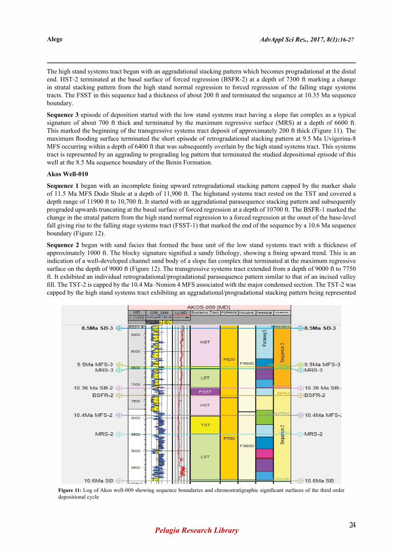
Akos Well-009
Sequence 2, the low stand systems tract began the sequence. A prograding complex capped the LST with a maximum regressive surface at a depth of 8500 ft (Figure 11). The low stand fan portion of well 009 is interpreted to be a localized region of interest for hydrocarbon bearing deposit in Akos field.
The early transgressive systems tract was characterized by an incised valley fill composed of a sand wedge of about 250 ft thick. Additionally, it was further capped by other retrograding facies that formed a seal on the underlying LST-2 deposit and terminated by the 10.4 Ma Nonion 4 maximum flooding surface at depth 8100 ft associated with warm condensed section embedded with some marine shales.

Alege AdvAppl Sci Res., 2017, 8(1):16-27
Pelagia Research Library23
Figure 9: Log of Akos well-002 showing sequence boundaries and chronostratigraphic significant surfaces of the third order depositional cycle
Figure 10: Akos well-007 showing sequence boundaries and chronostratigraphic significant surfaces of the third order depositional cycle
Alege AdvAppl Sci Res., 2017, 8(1):16-27
Pelagia Research Library24
The high stand systems tract began with an aggradational stacking pattern which becomes progradational at the distal end. HST-2 terminated at the basal surface of forced regression (BSFR-2) at a depth of 7300 ft marking a change in stratal stacking pattern from the high stand normal regression to forced regression of the falling stage systems tracts. The FSST in this sequence had a thickness of about 200 ft and terminated the sequence at 10.35 Ma sequence boundary.
Sequence 3 episode of deposition started with the low stand systems tract having a slope fan complex as a typical signature of about 700 ft thick and terminated by the maximum regressive surface (MRS) at a depth of 6600 ft. This marked the beginning of the transgressive systems tract deposit of approximately 200 ft thick (Figure 11). The maximum flooding surface terminated the short episode of retrogradational stacking pattern at 9.5 Ma Uvigerina-8 MFS occurring within a depth of 6400 ft that was subsequently overlain by the high stand systems tract. This systems tract is represented by an aggrading to prograding log pattern that terminated the studied depositional episode of this well at the 8.5 Ma sequence boundary of the Benin Formation.
Akos Well-010
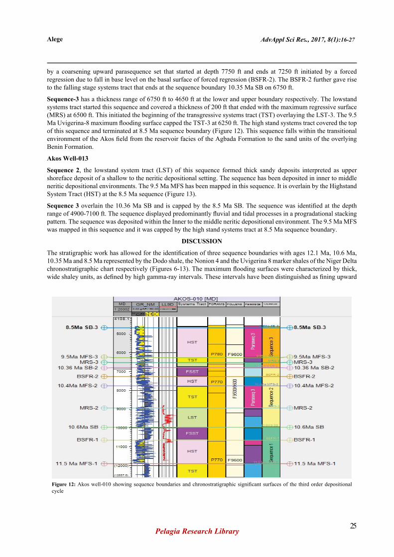
Sequence 1 began with an incomplete fining upward retrogradational stacking pattern capped by the marker shale of 11.5 Ma MFS Dodo Shale at a depth of 11,900 ft. The highstand systems tract rested on the TST and covered a depth range of 11900 ft to 10,700 ft. It started with an aggradational parasequence stacking pattern and subsequently prograded upwards truncating at the basal surface of forced regression at a depth of 10700 ft. The BSFR-1 marked the change in the stratal pattern from the high stand normal regression to a forced regression at the onset of the base-level fall giving rise to the falling stage systems tract (FSST-1) that marked the end of the sequence by a 10.6 Ma sequence boundary (Figure 12).
Sequence 2 began with sand facies that formed the base unit of the low stand systems tract with a thickness of approximately 1000 ft. The blocky signature signified a sandy lithology, showing a fining upward trend. This is an indication of a well-developed channel sand body of a slope fan complex that terminated at the maximum regressive surface on the depth of 9000 ft (Figure 12). The transgressive systems tract extended from a depth of 9000 ft to 7750 ft. It exhibited an individual retrogradational/progradational parasequence pattern similar to that of an incised valley fill. The TST-2 is capped by the 10.4 Ma–Nonion 4 MFS associated with the major condensed section. The TST-2 was capped by the high stand systems tract exhibiting an aggradational/progradational stacking pattern being represented
Figure 11: Log of Akos well-009 showing sequence boundaries and chronostratigraphic significant surfaces of the third order depositional cycle
Alege AdvAppl Sci Res., 2017, 8(1):16-27
Pelagia Research Library25
Figure 12: Akos well-010 showing sequence boundaries and chronostratigraphic significant surfaces of the third order depositional cycle
by a coarsening upward parasequence set that started at depth 7750 ft and ends at 7250 ft initiated by a forced regression due to fall in base level on the basal surface of forced regression (BSFR-2). The BSFR-2 further gave rise to the falling stage systems tract that ends at the sequence boundary 10.35 Ma SB on 6750 ft.
Sequence-3 has a thickness range of 6750 ft to 4650 ft at the lower and upper boundary respectively. The lowstand systems tract started this sequence and covered a thickness of 200 ft that ended with the maximum regressive surface (MRS) at 6500 ft. This initiated the beginning of the transgressive systems tract (TST) overlaying the LST-3. The 9.5 Ma Uvigerina-8 maximum flooding surface capped the TST-3 at 6250 ft. The high stand systems tract covered the top of this sequence and terminated at 8.5 Ma sequence boundary (Figure 12). This sequence falls within the transitional environment of the Akos field from the reservoir facies of the Agbada Formation to the sand units of the overlying Benin Formation.
Akos Well-013
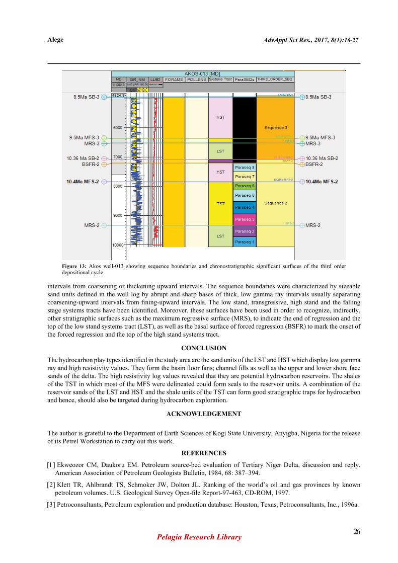
Sequence 2, the lowstand system tract (LST) of this sequence formed thick sandy deposits interpreted as upper shoreface deposit of a shallow to the neritic depositional setting. The sequence has been deposited in inner to middle neritic depositional environments. The 9.5 Ma MFS has been mapped in this sequence. It is overlain by the Highstand System Tract (HST) at the 8.5 Ma sequence (Figure 13).
Sequence 3 overlain the 10.36 Ma SB and is capped by the 8.5 Ma SB. The sequence was identified at the depth range of 4900-7100 ft. The sequence displayed predominantly fluvial and tidal processes in a progradational stacking pattern. The sequence was deposited within the Inner to the middle neritic depositional environment. The 9.5 Ma MFS was mapped in this sequence and it was capped by the high stand systems tract at 8.5 Ma sequence boundary.
DISCUSSION
The stratigraphic work has allowed for the identification of three sequence boundaries with ages 12.1 Ma, 10.6 Ma, 10.35 Ma and 8.5 Ma represented by the Dodo shale, the Nonion 4 and the Uvigerina 8 marker shales of the Niger Delta chronostratigraphic chart respectively (Figures 6-13). The maximum flooding surfaces were characterized by thick, wide shaley units, as defined by high gamma-ray intervals. These intervals have been distinguished as fining upward
Alege AdvAppl Sci Res., 2017, 8(1):16-27
Pelagia Research Library26
Figure 13: Akos well-013 showing sequence boundaries and chronostratigraphic significant surfaces of the third order depositional cycle
intervals from coarsening or thickening upward intervals. The sequence boundaries were characterized by sizeable sand units defined in the well log by abrupt and sharp bases of thick, low gamma ray intervals usually separating coarsening-upward intervals from fining-upward intervals. The low stand, transgressive, high stand and the falling stage systems tracts have been identified. Moreover, these surfaces have been used in order to recognize, indirectly, other stratigraphic surfaces such as the maximum regressive surface (MRS), to indicate the end of regression and the top of the low stand systems tract (LST), as well as the basal surface of forced regression (BSFR) to mark the onset of the forced regression and the top of the high stand systems tract.
CONCLUSION
The hydrocarbon play types identified in the study area are the sand units of the LST and HST which display low gamma ray and high resistivity values. They form the basin floor fans; channel fills as well as the upper and lower shore face sands of the delta. The high resistivity log values revealed that they are potential hydrocarbon reservoirs. The shales of the TST in which most of the MFS were delineated could form seals to the reservoir units. A combination of the reservoir sands of the LST and HST and the shale units of the TST can form good stratigraphic traps for hydrocarbon and hence, should also be targeted during hydrocarbon exploration.
ACKNOWLEDGEMENT
The author is grateful to the Department of Earth Sciences of Kogi State University, Anyigba, Nigeria for the release of its Petrel Workstation to carry out this work.
REFERENCES
[1] Ekweozor CM, Daukoru EM. Petroleum source-bed evaluation of Tertiary Niger Delta, discussion and reply. American Association of Petroleum Geologists Bulletin, 1984, 68: 387–394.
[2] Klett TR, Ahlbrandt TS, Schmoker JW, Dolton JL. Ranking of the world’s oil and gas provinces by known petroleum volumes. U.S. Geological Survey Open-file Report-97-463, CD-ROM, 1997.
[3] Petroconsultants, Petroleum exploration and production database: Houston, Texas, Petroconsultants, Inc., 1996a.

Alege AdvAppl Sci Res., 2017, 8(1):16-27
Pelagia Research Library27
[4] Doust H, Omatsola E. Niger Delta. In: Divergent/passive margin basins: American Association of Petroleum Geologists Bulletin Memoir, Edwards JD, Santogrossi PA (edtrs.), 1990, 48: 239-248.
[5] Michele LWT, Ronald RC, Michael EB. The Niger Delta Petroleum System: Niger Delta Province, Nigeria Cameroon, and Equatorial Guinea, Africa. USGS Open-File Report 99-50-H, 1999.
[6] Kulke H. Nigeria. In: Regional petroleum geology of the world. Part II: Africa, America, Australia and Antarctica, Berlin, Gebruder Borntraeger, Kulke H (edtr), 1995, 143-172.
[7] Evamy BD, Haremboure J, Kamerling P, Knaap WA, Molloy FA, et al. Hydrocarbon habitat of Tertiary Niger Delta. American Association of Petroleum Geologists Bulletin, 1978, 62: 1-39.
[8] Avbovbo AA. Tertiary lithostratigraphy of Niger Delta. American Association of Petroleum Geologists Bulletin, Tulsa, Oklahoma, 1978, 96-200.
[9] Helland-Hansen W, Martinsen OJ. Shoreline trajectories and sequences: Description of variable depositional-dip scenarios. Journal of Sedimentary Research, 1996, 66: 670–688.
[10] Hunt, Tucker. Stranded parasequences and the forced regressive wedge systems tract: deposition during base-level fall. Sedimentary Geology, 1992, 81: 1–9.
[11] Plint AG, Nummedal D. The falling stage systems tract: recognition and importance in sequence stratigraphic analysis. In: Sedimentary Responses to forced regressions, Hunt D, Gawthorpe R (edtrs), Geological Society of London, Special Publications, 2000, 172: 1-17.
[12] Catuneanu O, Willis AJ, Miall AD. Temporal significance of sequence boundaries. Sedimentary Geology,1998, 121: 157–178.
[13] Vail PR, Wonardt W. An integrated approach to exploration and development in the 90s: Well log-seismic sequence stratigraphy analysis. Gulf Goast Assoc of Geol Soc Trans, 1991, 41: 630–650.
[14] Van Wagoner JC, Mitchum RM, Campion KM, Rahmanian VD. Siliciclastic Sequence Stratigraphy in Well Logs, Cores and Outcrops. American Association of Petroleum Geologists, Tulsa, 1990, 55.
[15] Catuneanu O. Principles of Sequence Stratigraphy, Elsevier, Amsterdam, 2006, 375.
[16] Haq BU, Hardenbol J, Vail PR. Mesozoic and cenozoic chronostratigraphy and cycles of sea-level change. In: Sea-Level changes: an integrated approach: Society of Economic Paleontologists and Mineralogists, Wilgus CK(edtr), Special Publication, Miall, 1988, 42: 71-108.
[17] SEPM STRATA, 2016.