SeQual SAROS Oxygen System - Parnisari Arms RESCUE/9705_C_Saros... · TECHNICAL MANUAL SeQual®...
39
TECHNICAL MANUAL SeQual ® Technologies Inc. SAROS ™ Oxygen System Model 3000
Transcript of SeQual SAROS Oxygen System - Parnisari Arms RESCUE/9705_C_Saros... · TECHNICAL MANUAL SeQual®...

TECHNICAL MANUAL
SeQual® Technologies Inc.
SAROS™ Oxygen SystemModel 3000

GENERAL INFORMATION -----------------------------------------------2
SAROS OXYGEN SYSTEM SPECIFICATIONS -------------------------3
ELECTROMAGNETIC COMPATIBILITY --------------------------------5
HOW SAROS WORKS ----------------------------------------------------6
BASIC THEORY OF OPERATON ----------------------------------------6
ATF® CONCENTRATION MODULE -------------------------------7
COMPRESSOR -------------------------------------------------------7
BRUSHLESS COMPRESSOR MOTOR DRIVER (BCMD) -------7
COOLING FAN -------------------------------------------------------7
POWER BOARD -----------------------------------------------------7
SYSTEM BOARD-----------------------------------------------------7
CONTROL PANEL ---------------------------------------------------8
CONTINUOUS FLOW MODE -------------------------------------8
PULSE FLOW MODE WITH AUTOSAT TECHNOLOGY ------8
UTILITY MODE ------------------------------------------------------8
POWER SUPPLIES --------------------------------------------------9
AC POWER ADAPTER ----------------------------------------------9
24 VDC CABLE ------------------------------------------------------9
RECHARGEABLE BATTERY ----------------------------------------9
CHARGING ALGORITHM ---------------------------------------- 10
TRAINING INTRODUCTION ------------------------------------------ 11
TRAINING CHECKLIST ------------------------------------------------- 12
IMPORTANT SAFETY INSTRUCTIONS ------------------------------ 13
SYMBOLS USED -------------------------------------------------------- 13
INDICATIONS FOR USE ------------------------------------------------ 14
CONTRAINDICATIONS ------------------------------------------------ 14
SAFETY GUIDELINES --------------------------------------------------- 15
BATTERY SAFETY ----------------------------------------------- 16
TAbLE Of CONTENTS
INTRODUCTION TO YOUR SAROS OXYGEN SYSTEM -------- 16
DESCRIPTION OF THE SAROS (9400-SEQ)
ASSEMBLY (SHIPPABLE) ------------------------------------------ 17
INPUT/OUTPUT CONNECTIONS ---------------------------------- 19
USER-CONTROLS AND SYSTEM STATUS INDICATORS ------ 19
EXAMPLES OF LCD DISPLAY --------------------------------------- 21
RECOMMENDED OPERATING ENVIRONMENTS --------------- 22
OPERATION CHARACTERISTICS AT EXTREME
TEMPERATURES --------------------------------------------- 22
THE PROPER LOCATION ------------------------------------------
OPERATING INSTRUCTIONS ---------------------------------------- 23
POWERING ON SAROS ----------------------------------------- 23
GENERAL CHARGING INFORMATION ---------------------- 24
TYPICAL NEW BATTERY OPERATING TIME ---------------- 25
TYPICAL BATTERY RECHARGE TIME ------------------------ 26
INITIAL BATTERY CHARGING --------------------------------- 26
LOW BATTERY ALERTS ----------------------------------------- 27
OPERATING THE SAROS FOR THE FIRST TIME ----------- 27
ALERTS, ALARMS AND TROUBLESHOOTING TABLE --------- 31
SYSTEM TROUBLESHOOTING GUIDE ---------------------------- 31
SAROS OPTIONAL ACCESSORIES --------------------------------- 32
CLEANING, CARE AND ROUTINE MAINTENANCE ------------ 33
BATTERY CLEANING, CARE AND MAINTENANCE------------- 34
SHIPPING AND TRANSPORTING SAROS -------------------------- 34
STORING THE SAROS -------------------------------------------------- 35
DISCARDING THE SAROS --------------------------------------------- 35
ALARM INDICATIONS AND CODES -------------------------------- 35

Oxygen System Technical Manual
2
GENERAL INfORMATION
SeQual = Chart SeQual Technologies
This Technical Manual will familiarize you with information regarding the SAROS Oxygen System, Model 3000. Instructions in this manual are intended to help ensure that:
• Users are familiar with the SAROS system components and system principles of operation • Users are given proper guidance in the use of the SAROS and its accessories • Users are made aware of the care, maintenance, service and repair of the SAROS Oxygen System.
WARNING Important safety information for hazards that might cause serious injury. CAUTION Important information for preventing damage to the SAROS. DO NOT: Information needing special attention.
IMPORTANT! Clarifying information, specific instructions, or user reference information. WARRANTY 1 year or 1,000 hours, whichever comes first.

3
SAROS OXYGEN SYSTEM SPECIfICATIONSOxygen Concentrator
Dimensions • With battery • Without battery
26.80” long x 4.375” diameter23.25” long x 4.375” diameter
Weight • With Battery • Without Battery
12.25 pounds 10.00 pounds
Flow Settings • Continuous Flow • Pulse flow
• 1, 2, 3 LPM • 16, 32, 48, 64, 80, 96 ml
Continuous Flow Accuracy +/- 10% or 200ml/min, whichever is greater
Oxygen Concentration 93% +/- 3% for all flow settings
Maximum System Pressure 15 psig (103.5 kPa)
Oxygen Output Pressure 4.0 psig (27.6 kPa) nominal
Oxygen Concentration Status Indicator Green Light = Normal OperationYellow Light Flashing = Warning or Caution, less than 85% ± 3% Red Light = Abnormal Operation, less than 70% ± 5%
Nominal Sound Level <59 dB(A)
Operating Environment • Temperature • Humidity
32º F to 109º F (0° to 43°C) 10% to 95%, Non-condensing, 82.4°F (28°C) Maximum Dew point
Storage Environment • Temperature • Humidity
-4º F to 140º F (-20° to 60°C) Up to 95% Non-condensing
Nominal Power 3 LPM Continuous Flow ≤130 Watts
Nominal Battery operating time at 3 LPM Continuous Flow 30 Minutes
Continuous Flow Indication Expressed in liters per minute (LPM)
Audible Alarm Indicators • Loss of Power/Hot Battery • Low Battery • Low Oxygen Output • No breath detected • O2 Flow Outside Normal Limits • Low 9V battery • Unit Malfunction
Back-Up Alarm Power 9V Internal Battery
Filters Air Inlet Filter, HEPA and Exhaust Filter
Device Classification IEC Class I, Type B Applied Part, IPX1

Oxygen System Technical Manual
4
Pulse Mode Specifications
Pulse Settings 16, 32, 48, 64, 80, 96 ml
autoSAT Technology Servo-control to maintain consistent FiO2
Trigger Sensitivity Adjustable settings of 1 (most sensitive), 2 and 3 (least sensitive)
Trigger CriteriaCannula pressure has dropped below the trigger point (typically between 0.15 – 0.45 cm of H2O of negative pressure)
Minimum time between breaths 1.25 seconds (max. 3 consecutive breaths)
Response to Missing BreathsSwitch to Continuous Mode if no inspiration has been detected for 60 seconds with an audible alarm.
Bolus Volume and Breath Rates
bolus Size ml (± 15%) Max breath Rate
16 40
32 40
48 40
64 40
80 37
96 31
NOTE: At breath rate above Max Breath Rate, bolus size will be reduced proportionally.
Power Accessory Specifications
AC Power Adapter
Input Voltage 100- 240 VAC, 50 – 60 Hz
Input Power 245 – 260 VA
Output Voltage 24 VDC
Output Power 200 W
Battery Specifications
Output Voltage 14.8 VDC
Capacity 86 W-hours
Nominal Battery Life 80% Capacity after 200 Charge/Discharge cycles
Battery Recharge Time 1.5 hours to achieve 80% capacity from a fully discharged battery
24 VDC Cable
Input Voltage 20 – 28 VDC
Input Current 10 A

5
Independent Safety Testing
SAROS System and SAROS Concentrator, Model 3000
SafetyIEC 60601-1 : + A1, 1991 + A2, + Corrigendum EN 60601-1 + A1+ A2+ A12+ A13+ Corrigenda
Electromagnetic CompatibilityFCC 15B (Sec. 107 & 109), EN55011, EN60601-1-2 , EN6100-3-2, EN61000-3-3, IEC61000-4-2, IEC61000-4-3, IEC61000-4-4, IEC61000-4-5, IEC61000-4-6, IEC61000-4-8, IEC61000-4-11, IEC 60601-1- 2, RTCA DO 160 Rev F
AC Power Adapter
Safety IEC 60601-1 + A1 + A2:
Electromagnetic CompatibilityFCC 15B (Sec. 107 & 109), EN55011, EN60601-1-2, EN6100-3-2, EN61000-3-3, IEC61000-4-2, IEC61000-4-3, IEC61000-4-4, IEC61000-4-5, IEC61000-4-6, IEC61000-4-8, IEC61000-4-11, EN55014-1
24 VDC Cable
Safety Portions of IEC 60601-1 + A1 + A2
Electromagnetic Compatibility FCC 15B (Sec. 109), EN55011, EN60601-1-2, IEC61000-4-2, IEC61000-4-3, IEC61000-4-4, IEC61000- 4-6, IEC 60601-1-2
battery
Safety UL2054, UL60950-1, First Edition (UL File MH29443), IEC 60601-1 + A1 + A2, UN Transportation Tests T1-T8
Electromagnetic Compatibility EN 61000-6-3, (EN55022), EN61000-6-1, EN61000-4- 2, EN61000-4-3.
ELECTROMAGNETIC COMPATIbILITYThis equipment complies with the limits for medical devices to the IEC60601-1-2 Electromagnetic Compatibility Standard. These limits are designed to provide reasonable protection against harmful interference in a typical medical installation. The equipment generates, uses and radiates radio frequency energy and, if not installed according with the instructions, may cause harmful interference to other devices in the vicinity. However, there is no guarantee that interference will not occur in a particular installation. If this equipment does cause harmful interference to other devices, which can be determined by turning the equipment off and on, the user is encouraged to try to correct the interference by one or more of the following measures:
- Reorient or relocate the receiving device.
- Increase the separation distance between the equipment.
- Connect the equipment into an outlet on a circuit different from that which the other device(s) are connected.
- Consult with SeQual Technical Support for help.
Guidance and Manufacturer’s declaration - electromagnetic emissions
The SeQual SAROS Oxygen System is intended for use in the electromagnetic environment specified below. The customer or the user of the SeQual Technologies SAROS Oxygen System should assure that it is used in such an environment.
Emissions Test Compliance Electromagnetic environment - guidance
RF emissions EN 55011
Group 1
The SeQual Technologies SAROS Oxygen System uses RF energy only for its internal function. Therefore, its RF emissions are very low and are not likely to cause any interference in nearby electronic equipment.
RF emissions EN 55011
Class B The SeQual Technologies SAROS Oxygen System is suitable for use in all establishments, including domestic establishments and those directly connected to the public low - voltage power supply network that supplies buildings used for domestic purposes.
Harmonic emissions IEC 61000-3-2 Class A
Voltage fluctuations/ flicker emissions IEC 61000-3-3 Complies

Oxygen System Technical Manual
6
HOW SAROS WORKS
INTRODUCTIONThe SAROS Oxygen System, Model 3000 with autoSAT Technology is a portable medical device used to extract oxygen from the atmosphere, concentrate it to greater than 90% and flow it through the oxygen outlet port. The device will operate in Continuous flow or Pulse flow modes. In Continuous Flow Mode the oxygen is provided at a constant flow rate of 1, 2, or 3 LPM. In Pulse flow Mode, oxygen is supplied in a bolus at the beginning of each inspiration, providing a selectable range setting of flow between 16 ml and 96 ml, in increments of 16 ml.
SAROS is BTP (Body, Temperature, and Pressure) compensated. It delivers oxygen by accounting for difference between ambient conditions and those found in the patient’s lungs (37°C).
SAROS operates from external power, AC or 24VDC, or from a rechargeable Battery. The system includes a “Smart Battery” charger that recharges the Battery whenever the SAROS is connected to external power. The system monitors and controls both the power source and the Battery Charger.
BASIC THEORY OF OPERATIONSAROS Oxygen System uses a variable speed compressor to provide both positive and negative air pressure and is driven by a Brushless DC Motor (BLDC) and drive system.
The ATF® Concentrator Module accepts positively and negatively pressurized air and extracts oxygen from this air using the Pressure Swing Adsorption (PSA) process. The ATF module sub-components consist of patented rotary valves, manifold, housing, sieve beds, and a stepper motor / gear drive system. The rotary valve system channels the gas in a sequential manner to each of the sieve beds. Each bed is pressurized to force the oxygen through the sieve and into the product tank while most of the nitrogen is separated and remains in the sieve. Once the process is maximized then the sieve beds are purged of the nitrogen. The purged nitrogen is then vented to atmosphere through the exhaust vent. The process is continuously repeated in each sieve bed.
The flow of produced oxygen passes from the product tank to a flow and concentration monitoring and control system which utilizes a proprietary ultrasonic flow and concentration sensor. It then continues through a flow control valve to accurately control the flow of oxygen in continuous and pulse flow modes. The oxygen then passes through a HEPA filter and is delivered to the oxygen outlet port.
The oxygen flow rate and mode are selected by the user. In continuous flow mode, oxygen is delivered continuously at rates of 1, 2, and 3 LPM and, in pulse flow mode; a bolus is delivered at the beginning of each inspiration with selectable volume delivery approximately equivalent to rates between 16 and 96 mL.
The SAROS electronic system, together with embedded operational firmware, provide the means to manage power, control oxygen production, monitor safety functions and interface with the user. Power management functions include switching between various power inputs, driving the compressor, ATF stepper motor, and proportional valve, monitoring battery status and charging when power is available from an external source. System management functions include monitoring all flow, pressures, concentrations and safety functions. User Interface components such as buttons, illuminated indicators, LCD display and audio transducer are also monitored or controlled. The User Interface informs the user of the system status, allows the user to select a continuous flow or pulse mode flow setting and the ability to set the desired flow rate. The Utility Button the User Interface also allows the User to obtain information about the system – hours of operation, software version and 9V battery status - or make selections on various features such as Tactical or Normal Mode, Trigger Sensitivity Adjustments, Buzzer loudness and LCD Brightness and Contrast.

7
ATF® CONCENTRATOR MODULEThe SAROS Oxygen System, Model 3000 with autoSAT Technology uses a passive system to separate oxygen from air. Air flows into the SAROS where it is filtered and then enters the compressor. Pressurized air flows from the compressor into the ATF Concentrator Module where it is separated into oxygen and nitrogen components. The air separation process uses a rotary valve system to force air through a series of pressurized sieve beds. Through a process known as “pressure swing adsorption,” nitrogen molecules are collected on an adsorbent material or zeolite allowing the concentrated oxygen to be forced through a sieve bed into the product tank. The nitrogen molecules are then purged from the adsorbent material using a vacuum pressure cycle.
Oxygen flows from the product tank through a sensor that measures flow and concentration and then through a HEPA filter. A flow control valve regulates the flow of concentrated oxygen. The process is continuously repeated during operation.
COMPRESSORThe SAROS compressor is a two-head variable speed compressor driven by a highly efficient Brushless DC (BLDC) motor. When air flows into the compressor, it passes through an air inlet mesh filter that filters out impurities. Using one head, the compressor takes in filtered air, compresses it and channels the compressed gas to the ATF Module. The second head pulls a vacuum on the ATF module and exhausts nitrogen rich gas through an exhaust outlet muffler to suppress the noise and then to the exhaust vent at the bottom of the device.
BRUSHLESS COMPRESSOR MOTOR DRIVER (BCMD)The BCMD drives the compressor motor based on the input power from either the battery, the AC Power Adapter or the 24 VDC Cable.
COOLING FANA cooling fan is installed in the SAROS to provide forced air cooling to the various components in the system that generate heat.
POWER BOARDThe Power Board takes external power that comes into the SAROS from the AC Power Adapter, 24 VDC Cable or Battery and monitors and controls power distribution to the rest of the SAROS system. The Power Board also drives the cooling fan.
SYSTEM BOARDThe System Board is the center of nearly all the SAROS functions. The System Board is a microcontroller-based system that monitors system dynamics such as temperatures, pressures, ATF stepper motor and proportional valve, product flow and concentration, and the Users’ input, indicators and buzzer operation and external communications. It measures temperature of the oxygen, compressor motor, ambient temperature, and ATF temperature, BCMD, Power Board and the Battery.
The System Board utilizes a proprietary ultrasonic flow and concentration sensor and a flow control valve to accurately control the flow oxygen in the various flow delivery modes.

Oxygen System Technical Manual
8
CONTROL PANELThe Control Panel provides a user interface consisting of a membrane panel keyboards, Liquid Crystal Display (LCD), external power present indicator, Battery capacity indicator, alarm status indicators, and a buzzer. The user interface informs the user of the system status and allows the user to set the desired flow modes and flow rate – continuous or pulse, display mode – normal or tactical, set up system parameters and acquire system information.
CONTINUOUS FLOW MODEThe user may set the SAROS oxygen flow rate and mode. Continuous Flow Mode delivers a constant flow of oxygen to the Oxygen Outlet Port at settings of 1, 2, and 3 LPM. Within the SAROS, concentrated oxygen is stored in a product tank at pressures in the range of 5 – 9 psi and is back-pressure compensated. This pressure gives Continuous Flow Mode the capability to deliver the indicated flow rate to the patient even if extension tubing is used, up to 50 feet long. In addition, the SAROS Continuous Flow Mode is fully compatible with humidifier use.
PULSE FLOW MODE WITH autoSAT TECHNOLOGYThe SAROS Pulse Flow Mode with autoSAT Technology delivers a high flow of oxygen at the very beginning of each inspiratory effort. The approach is based on the manner in which gas is delivered into a patient’s airway. The user may select pulse volume delivery rates between 16 and 96 ml. Pulse durations vary between 100 milliseconds and 500 milliseconds due to dead space considerations. The fundamental approach to triggering and controlling the oxygen bolus in Pulse Flow Mode is:
The user may select pulse trigger sensitivity in settings 1 (most sensitive), 2, or 3 (least sensitive). The pulse will be triggered when the system meets all the following criteria:
• The cannula pressure has dropped below the trigger point (typically between 0.15 and 0.45 cmH2O). • At lest 1.25 seconds has passed since the last pulse began.
The SAROS autoSAT Technology consistently maintains the FiO2 by adjusting to the patient’s respiratory rate. As their rate increases, the autoSAT feature servo controls the device to automatically increase oxygen output to ensure uninterrupted delivery of the set bolus volume. autoSAT provides the patient with unparalleled performance without limiting available oxygen, enabling the system to automatically adjust to increased oxygen demands that often occur.
UTILITY MODEA User or Service Technician can access the Utility Mode function by pressing using the Utility Button on the control panel. All information is displayed on the LCD. Advance to the next feature in the Utility Mode by depressing the Utility Button. The “+” or “-“ button is used to toggle when a feature is selected. Pressing the Flow Mode button takes you back one step.

9
POWER SUPPLIESSAROS may operate from either an AC Power Adapter, 24 VDC Cable or Battery. When power is available from an external supply, the SAROS will draw from the external source rather than depleting the Battery. Connection to external power is indicated when the External Power Present Indicator located on the Control Panel is illuminated.
AC POWER ADAPTERThe AC Power Adapter is a universal input type, capable of accepting 100 – 240 VAC, 50/60 Hz. It is capable of delivering up to 200W at 24 VDC output. The input cord requires a grounded receptacle. Country specific cords may be used with the AC Power Adapter, as the supply is equipped with a universal input receptacle. When used in a medical care facility, international safety standards require the use of hospital grade AC power cord with the SAROS. The AC Power Adapter contains protection circuits for output over-current, input over-voltage, and internal over-temperature conditions. If any of these conditions exist, output power will be a Loss of Power Alarm. Refer to Alert, Alarms and Troubleshooting Table. These three conditions are self-resetting, such that output power will resume when protection circuits fall back into acceptable operating ranges.
24 VDC CABLE The 24 VDC Cable is intended for use with 24 volt power sources, such as those found in various vehicles.
RECHARGEABLE BATTERYThe Battery allows operating the SAROS away from AC or DC power. The Battery used with the SAROS contains Lithium Ion battery cells, similar to those used in laptop computers and cell phones. The SAROS Battery is approximately 86 W-hours in capacity and provides an output voltage of 12V to 16.6V. The Battery connects to the bottom of the SAROS and is secured by a mechanical latching mechanism. The Battery can be recharged when the SAROS is connected to the AC Power Adapter or the 24 VDC Cable. The Battery Gauge indicator on the SAROS LCD will have a “waterfall” effect when the Battery is charging. The fastest way to recharge the Battery is using the AC Power Adapter.
The Battery has an integral safety circuit that prevents over charge, over discharge or damage due to an external short circuit of the pack. An Integral fuel gauge communicates battery voltage, current, charge state, and temperature. Based on the voltage supplied by the Battery, the system is configured to optimize battery charging by regulating the charging voltage and current as follows:

Oxygen System Technical Manual
10
battery Pack Output Voltage (VDC) Charging Voltage (VDC) Charging Current (A)
< 10.0 FAULT FAULT
10.0 – 11.9 16.6 0.55 to 0.70
> 12.0 16.6 5.60
When the SAROS is operating on Battery power, the LCD displays an estimate of the amount of time the unit can operate at the current settings, within +/- 5 minutes. When the SAROS is operating on Battery and the time on battery falls below 15 minutes, the LCD time on battery characters will flash to indicate a low battery condition.
The capacity of the SAROS Battery is determined by electronics and software. While the SAROS Battery allows the concentrator to operate at its full range of capabilities, the primary purpose of the Battery is to allow an autonomous system while moving between AC or DC power sources. The SAROS’s Battery, like all lithium ion batteries, is susceptible to permanent damage from excessive heat. Exposure to excessive heat may shorten the Battery’s service life.
The Battery contains multiple temperature sensors to monitor battery cell temperature. The amount of heat the Battery can safely endure varies depending on how the Battery is being used. During discharge, the SAROS software will shut the system down if internal battery cell temperature exceeds 59°C. While the Battery is charging, software will interrupt charger operation when the internal battery temperature exceeds 40°C or temperature is less than 5°C. In both of these cases, when internal battery cell temperature returns within these limits, the SAROS will resume normal operation. Operation near these temperature limits will not damage the Battery, but are in place to ensure that the service life of the Battery is preserved.Heat in the Battery is generated during discharge, and can also be the result of operating the SAROS in high ambient temperatures. The amount of internally generated heat varies with the flow setting – higher flows induce greater Battery heating. While high ambient temperatures are typically the result of operation on a hot day, running the SAROS with inadequate ventilation can also cause additional heat. Always ensure that the SAROS is operated in a well-ventilated space, the air intake filter is clean, and intake and exhaust vents are unobstructed.
CHARGING ALGORITHMThe charging algorithm is performed by the Power Board software and involves three basic decisions:
1. When to start charging
2. How fast to charge
3. When to stop charging
Charging begins when Battery voltage falls below 90% relative capacity. The charging current is limited by the charger capability and the rated capacity of the Battery. Under certain conditions, the SAROS may not have enough external power available to charge the batteries at the full rate. In this case, the charging rate will be limited to the available power. As the Battery accumulates charge, the charging current required will eventually fall. Battery charging will cease when the Battery voltage is greater than 16V, charge current is less than 0.66A, and relative charge is greater than 93%.
The software will only charge when the Battery temperature is at or below 40°C. The software will always run the cooling fan whenever the charger is enabled. The Battery Charger is disabled and the cooling fan is set to maximum whenever the Battery temperature exceeds 40°C. The Battery charger is disabled when temperature is less than 5°C.
All lithium ion batteries self-discharge at very low rates when not in use. SAROS Batteries are shipped from SeQual in a partially charged state (nominally 40%). When the Battery is stored in a cool, dry location, it is recommended to recharge the Battery every 3 months. SeQual recommends a first in, first out rotation of Battery inventory for maximum service life.

11
TRAINING INTRODuCTION
Basic Concept TrainingThe following section is intended to assist the Trainer to provide a basic overview of the SAROS Oxygen System for Set up, use, routine maintenance and trouble shooting. A Check List is provided to assist you in covering various aspects of the system. Proper training of the users will result in fewer service calls, improved compliance and utilization of the SAROS to its fullest capability.
Pre-Delivery Check ListBefore delivering the device, check and log the status of the following:
Parts Inventory – Verify that each SAROS is provided with the following items: • Technical Manual • Maintenance Manual • SAROS Concentrator • Cannula • AC Power Cord • AC Power Adapter • 24 VDC Cable • Battery • Spare Filter Set
Power Sources – Insert and check the following for proper operation: • AC Power Adapter with Power Cord • 24 VDC Cable • Battery
Electrical System – Use the Control Panel to check and/or adjust the following:
feature factory Default
Alarm Codes AC=NONE
Pulse Sensitivity Setting 2
LCD Contrast 3
Normal Mode Brightness 3
Tactical Mode Brightness 2
Tactical Buzzer Volume 2
Tactical or Normal Mode TACT OFF
9V Battery Status GOOD
Hours of Operation Actual Hours
System Software Part Number and Revision Latest Revision
Motor Software Part Number and Revision Latest Revision

Oxygen System Technical Manual
12
TRAINING CHECK LIST
TRAINING TOPIC INITIALS/DATE
Pre-Delivery check List
Indications for Use
Contraindications
bASIC CONCEPT TRAINING
Read the Technical Manual
Device Specifications
Safety Guidelines, Warnings/Cautions
Locating Device
User Panel Buttons and Indicators
Alerts and Alarms
Attaching the AC Power Adapter
Attaching the 24 VDC Cable
Attaching and removing the Battery
Turning the device ON and OFF
Selecting Flow Mode and Settings
- Selecting Continuous Flow Mode
- Selecting Pulse Flow Mode with autoSAT
Reading the Display
Accessing the Utility Menu
- Alarm codes
- Pulse Sensitivity Setting
- LCD Contrast
- Normal Mode Brightness
- Tactical Mode Brightness
- Tactical Buzzer Volume
- Turn ON Tactical Mode
- 9V Battery Status
- Hours of Operation
- System Software Part Number and Revision
- Motor Software Part Number and Revision
CLEANING, CARE AND MAINTENANCE
- Device and accessory cleaning
- Replacing the filters and 9V battery
TROubLESHOOTING AND REPAIR
TRAINED bY:

13
IMPORTANT SAfETY INSTRuCTIONSSeQual® Technologies Inc. (SeQual) recommends that this Technical Manual be given to each user receiving a SAROS Oxygen System. This manual provides all of the necessary information needed for a user or clinician to successfully operate the SAROS.
SYMbOLS uSED IN THE TECHNICAL MANuAL AND ON SAROSRefer to this section for an explanation of the symbols and the Warnings that accompany them.
Read Instructions Please consult the Technical Manual instructions provided with the product.
Attention or Caution Indicates important information that requires the user to take special precautions when certain conditions are present.
No Smoking or Open flames The use of oxygen requires that special care be taken to reduce the risk of fire. Materials that burn in air, and even some materials that will not burn in air, are easily ignited and burn more rapidly in high concentrations of oxygen. For safety concerns, all possible sources of ignition must be kept away from the SAROS and preferably out of the room in which it is being used. Smoking in the proximity of an operating SAROS is dangerous, and can permanently damage the device and void the warranty.
use No Oils or Grease Indicates important information about the possibility of spontaneous and violent ignition that may occur if oils, grease or other petroleum based substances come into contact with oxygen under pressure.
IPX2 Dripping Rain The SAROS Battery will provide protection against water ingress according to the specifications indicated. Water sprayed at an angle up to 15° on the outside shall have no harmful effects.
IPX1 Drip Proof Equipment-IPX1 The SAROS, the AC Power Adapter and 24 VDC Cable provides protection against the harmful effects of the ingress of liquids.
IEC Icon for DC Power (Input) Indicates equipment providing a particular degree of protection against electric shock, particularly regarding: • Allowable leakage current; • Reliability of the protective earth connection (grounding).
Type b Equipment
Amperes
Alternating Current
Audible Alarm An audible indicator is provided to announce a reduction in oxygen concentration or when the power has been interrupted or lost.
ON/Off (Standby) Powers the device ON or OFF, but does not directly disconnect the mains power.
Increase flow Setting Increases the flow setting by 1 LPM and pulse volume by 16 mL increments each time the button is pressed.
Decrease flow Setting Decreases the flow setting by 1 LPM and pulse volume by 16 mL increments each time the button is pressed.
flow Mode Activates either Continuous Flow Mode or Pulse Flow Mode Operation.

Oxygen System Technical Manual
14
External Power is Present Indicator
Indicates the presence of external power.
battery Status Gauge Shows the amount of charge remaining in the Battery.
O2Oxygen Output The port from which the oxygen flows and where the tubing or interface (standard nasal cannula) is
attached.
utility The Button that activates a Utility Menu to access information or to change settings.
Recycle Symbol
Do Not Discard, Recycle. Contact the local city or town offices for instructions on proper disposal of the Battery, electrical or electronic equipment.
EC REP Authorized European Representative
Name and Address of Manufacturer
INDICATIONS fOR uSE
SAROS OXYGEN SYSTEM IS INDICATED FOR THE ADMINISTRATION OF SUPPLEMENTAL OXYGEN. THE DEVICE IS NOT INTENDED FOR LIFE SUPPORT NOR DOES IT PROVIDE ANY PATIENT MONITORING CAPABILITIES.
A PHYSICIAN HAS PRESCRIBED A SPECIFIC OXYGEN FLOW SETTING TO MEET AN INDIVIDUAL’S NEEDS. OXYGEN FLOW SETTINGS SHOULD BE ADJUSTED ONLY UNDER THE DIRECTION OF A PHYSICIAN
WARNING FEDERAL U.S. LAW RESTRICTS THIS DEVICE TO SALE BY OR ON THE ORDER OF A PHYSICIAN.
CONTRAINDICATIONS
WARNING IN CERTAIN CIRCUMSTANCES, THE USE OF NON-PRESCRIBED OXYGEN CAN BE HAZARDOUS. THIS DEVICE SHOULD ONLY BE USED UNDER THE DIRECTION OF A PHYSICIAN OR QUALIFIED CLINICIAN.
NOT FOR USE IN THE PRESENCE OF FLAMMABLE ANESTHETICS.
AS WITH ANY ELECTRICALLY POWERED DEVICE, THE USER MAY EXPERIENCE PERIODS OF NON-OPERATION AS A RESULT OF ELECTRICAL POWER INTERRUPUTION, OR THE NEED TO HAVE THE SAROS SERVICED BY A QUALIFIED TECHNICIAN. SAROS IS NOT APPROPRIATE FOR ANY PATIENT WHO WOULD EXPERIENCE ADVERSE HEALTH CONSEQUENCES AS THE RESULT OF SUCH TEMPORARY INTERRUPTION.
USE OF AN OXYGEN MASK IS CONTRAINDICATED DUE TO THE POSSIBILITY OF REBREATHING EXHALED CARBON DIOXIDE.

15
SAfETY GuIDELINES
These are WARNINGS and CAUTIONS that apply to hazards or unsafe practices that could result in serious injury or property damage.
• Keep SAROS and the power cord away from hot surfaces or open flames.
• SAROS should be located in a well-ventilated area to allow for adequate air intake.
• Avoid the intake of airborne pollutants, smoke and fumes.
• ONLY use this device with accessories specified by, or recommended by, SeQual.
• If SAROS has been dropped, damaged or exposed to water, please contact a qualified technician for inspection or possible repair of the device.
• When using SAROS in any vehicle, be sure it is properly secured, belted or restrained.
• DO NOT use SAROS if it has a damaged power cord or plug. • DO NOT drop or insert any objects into any opening on the device.
• DO NOT block the air inlet or the exhaust vent of the SAROS when it is on a soft surface, such as a litter, bed, chair, carpet, couch or vehicle seat.
• DO NOT cover the device with a blanket, towel or sheet, etc.
• DO NOT overfill the optional humidifier. Fill the optional humidifier with water to the level shown by the manufacturer of the humidifier.
WARNING DO NOT REMOVE THE COVER. THERE ARE NO USER-SERVICEABLE PARTS INSIDE THE DEVICE. ONLY QUALIFIED SERVICE PERSONNEL SHOULD REMOVE THE COVER OF THE DEVICE.
DO NOT OPERATE THE DEVICE, COMPONENTS OR ACCESSORIES ON WET SURFACES OR IN STANDING WATER AND DO NOT SUBMERSE IN WATER.
PROTECT ELECTRICAL POWER CORDS FROM SHARP EDGES. ELECTRICAL SHOCK AND SERIOUS PHYSICAL INJURY MAY OCCUR.
ONLY USE THE SEQUAL SUPPLIED AC POWER ADAPTER AND 24 VDC CABLE WITH THE SAROS. USE OF ANY OTHER AC POWER ADAPTER OR DC CABLE MAY BE HAZARDOUS, CAUSE SERIOUS DAMAGE TO THE SAROS AND WILL VOID THE WARRANTY.
AVAILABILITY OF AN ALTERNATE, OR BACK-UP, SOURCE OF SUPPLEMENTAL OXYGEN IS RECOMMENDED IN CASE OF A POWER OUTAGE OR A MECHANICAL FAILURE OF THE DEVICE.

Oxygen System Technical Manual
16
CAUTION LOCATE OXYGEN SUPPLY TUBING AND ALL POWER CORDS IN A MANNER TO PREVENT TRIPPING HAZARDS.
DO NOT PLACE THE SAROS IN A SMALL, ENCLOSED SPACE, SUCH AS A BATHROOM, CLOSET, BAG OR BOX WITH THE OXYGEN CANNULA OR TUBING LEADING OUT OF THE ENCLOSED SPACE.
DO NOT EXPOSE THE DEVICE TO TEMPERATURES OUTSIDE OF THE SPECIFIED RANGE OF OPERATING OR STORAGE TEMPERATURES AS THIS MAY DAMAGE THE DEVICE.
bATTERY SAfETY
WARNING DO NOT DISASSEMBLE, PUNCTURE, OR CRUSH THE BATTERY. BATTERY ELECTROLYTES MAY BE TOXIC IF SWALLOWED AND CAN BE HARMFUL TO SKIN AND EYES. KEEP THE BATTERY AWAY FROM CHILDREN.
DO NOT SHORT-CIRCUIT THE BATTERY’S METAL CONTACTS WITH METALLIC OBJECTS, SUCH AS KEYS OR COINS. THIS MAY CAUSE SPARKS OR EXCESSIVE HEAT TO BE GENERATED.
USE OF A DAMAGED BATTERY MAY CAUSE PERSONAL INJURY
THE BATTERY MAY EXPLODE AND CAUSE POTENTIAL INJURY IF EXPOSED TO A FIRE, OR DISPOSED OF IN A FIRE.
EXPOSING THE BATTERY TO WATER OR OTHER LIQUIDS MAY CAUSE PERSONAL INJURY.
CAUTION DO NOT EXPOSE THE BATTERY TO TEMPERATURES ABOVE 140° F (60°C), SUCH AS IN A VEHICLE PARKED IN THE SUN ON A HOT DAY.
IT IS NOT RECOMMENDED THAT THE BATTERY IS CHARGED BELOW 41 F° (5° C) OR ABOVE 104° F (40° C).
ONLY USE THE BATTERY FOR ITS INTENDED PURPOSE.
PUSH LOCKING/UNLOCKING BUTTON BEFORE INSTALLATION
INTRODuCTION TO YOuR SAROS OXYGEN SYSTEM This Technical Manual will inform you about the use and care of the SAROS, its standard components and the optional accessories. Please read thoroughly all of the information in this manual before operating the SAROS and receive proper training on the use and care of this device.
A PHYSICIAN HAS PRESCRIBED SUPPLEMENTAL OXYGEN AS PART OF A TREATMENT PLAN TO MEET AN INDIVIDUAL’S CLINCIAL NEEDS. OXYGEN FLOW MODES AND SETTINGS SHOULD BE ADJUSTED ONLY UNDER THE ADVICE OF A PHYSICIAN OR CLINICIAN.

17
Saros Shell
9VBattery
(9257-SEQ)
ParticulateMesh/Inlet
Filter (9798-SEQ)
Cover
OxygenOutlet Port
HEPAFilter
(9765-SEQ)
Simplified UserInstructions
Label (behind)
Main/Rating Label
(underneath)Battery(9723SN-SEQ)
A representation of the major features of the SAROS hardware interface are shown below: • Membrane Panel containing: - Five tactile buttons allow control of all user controllable settings - Five variable intensity LED indicators provide overall status - An 8 character LCD display shows settings • 9V Battery • Oxygen Outlet Port • External Power Connector • Data Communications Connector • Battery • Simplified User Instructions Label • Main / Rating Label • Particulate Mesh/Inlet Filter
DESCRIPTION Of THE SAROS (9400-SEQ) ASSEMbLY—SHIPPAbLE
Become familiar with the key features of the SAROS and the user control panel.
ADDITIONAL PARTSDC Power Supply: 9727SN-SEQAC Power Supply: 9726SN-SEQ with Power Cord 3588-SEQ

Oxygen System Technical Manual
18
FRONT – CONTROL PANEL BACK – SIMPLIFIED INSTRUCTIONS
TOP BOTTOM – WITHOUT BATTERY
SERVICE PORT (USB) BOTTOM - WITH BATTERY
Air Inlet
Oxygen Outlet Port
Main/RatingLabel
BatteryConnector
ExternalPower
Connector

19
INPuT/OuTPuT CONNECTIONS
Oxygen Outlet Port Oxygen supply tubing or a cannula is attached to this port.
Particulate Mesh/ Inlet Filter Ambient air is drawn into the device through the air inlet located at the top of the device. This air inlet filter prevents dust /debris from entering the SAROS and should be cleaned regularly.
Service Port This connection is designed for factory use only.
External Power Receptacle The SAROS AC Power Adapter or 24 VDC Cable connects to this receptacle.
Exhaust Vent Exhaust air from the SAROS leaves the device from this vent.
uSER CONTROLS AND SYSTEM STATuS INDICATORSThe SAROS User Control Panel displays important operating information. This section will help you understand this operating information.
Normal Mode provides all LED indications with full brightness, full audio indicator sound and LCD backlight. The system always starts up in Normal Mode. Normal Mode can be changed to Tactical Mode by depressing the Utility Button and then the Decrease button to change from TACT=ON to TACT=OFF. Normal Mode is indicated by an “N” on the LCD.
Tactical Mode is provided for operation where noise and light may compromise a situation. In these situations, the LED indicators will be off and the audio indicator sound is reduced. Tactical Mode can be changed to Normal Mode by depressing the Utility Button and then the Decrease button to change from TACT=ON to TACT=OFF. Tactical Mode is indicated by a “T” on the LCD.
Green, Yellow, and Red Indicators on the front panel indicate the operating condition of the device. For additional information on these indicators see the Alerts, Alarms and Troubleshooting Table in this manual. ON/Off (Standby) button -Green Indicator: This button powers the device ON or powers it OFF. The Green Indicator
Exhaust Vent
Push Buttonto Release
Battery

Oxygen System Technical Manual
20
is illuminated when the device is powered ON and operating in the Normal Mode and off when operating in Tactical Mode.
Increase or Decrease flow Setting button: Use these buttons to set the flow or to make selections in the Utility Menu.
Delivery Mode button and Indicator (blue): The SAROS contains a button to toggle between Continuous Flow and Pulse Flow mode. The Pulse Flow mode activates autoSAT Technology – as breath rate changes, the system adjusts to provide a consistent bolus size. The Pulse Flow Mode allows a significant increase in operating time when powered by a Battery. When the Pulse Flow Mode is activated, the blue Flow Mode Indicator illuminates and a pulse of oxygen is delivered with each inspiratory effort. When the pulse of oxygen is delivered, the flow mode indicator turns off.
ALERT (Yellow) Indicator - Low and Medium Priority Alerts: In Normal Mode, when illuminated, this indicates a low priority awareness condition or Caution. Continue to use your system and refer to the Alerts, Alarms, and Troubleshooting Table for the proper response. A flashing yellow indicates a medium priority alert. A prompt response is necessary. In Tactical Mode, a blinking star “*” indicates an alert.
ALARM (Red) Indicator – High Priority Alarms: In Normal Mode, when illuminated, this indicates a high priority alarm condition. An immediate response is necessary. Refer to the Alerts, Alarms, and Troubleshooting Table and contact a qualified service technician. In Tactical Mode, a blinking star “*” indicates an alert.
buzzer: An audible alarm (or buzzer) is used to alert you to the operating condition of the device, either a warning or failure, and to confirm a valid key press by the user.
flow Setting Indicator: This is the main focus on your control panel. A clinician will correctly set the prescribed flow for either the CX - Continuous Flow Mode at X LPM (1, 2 or 3) and/or the PXXX - Pulse Flow Mode XXX ml (16, 32, 48, 64, 80, 96) settings. Each time the device is turned ON, it will operate at C3 (3 LPM) continuous flow in the Normal Display Mode.
battery Status Gauge: This indicator displays the charge remaining in the Battery. When the Battery is fully charged all 5 gray bars are illuminated. Each gray bar represents approximately 20% of the total Battery charge. When the Battery is being charged, the charge indicator bars will waterfall. If the Battery is not installed, or if it is improperly installed, the Battery Status Gauge will not be illuminated and Time on Battery is not displayed.
External Power is Present Indicator: When the SAROS is properly plugged in and is using the AC or 24 VDC Cable, this indicator will illuminate on the User Control Panel in Normal Mode.
EXAMPLES Of LCD DISPLAY AT POWER uP

21
Example of LCD Display indicates the following information:
Continuous Flow at 3 LPM, Tactical Mode, Battery between 81% and 100% of capacity, 29 minutes of battery operating time remains. Battery symbol is animated with a waterfall effect when charging.
Example of LCD display during Continuous Mode
Example of LCD Display indicates the following information:
Continuous Flow at 2 LPM, Normal Mode, Battery between 61% and 80% of capacity, 24 minutes of battery operating time remains. Battery symbol is animated with a waterfall effect when charging.
Example of LCD display during Pulse Mode
Example of LCD Display indicates the following information:
Pulse mode at bolus size of 48 mL, Tactical Mode, Battery between 61% and 80% of capacity, 1.1 hours of battery operating time remains. Battery symbol is animated with a waterfall effect when charging.

Oxygen System Technical Manual
22
RECOMMENDED OPERATING ENVIRONMENTS
The following chart provides important information concerning the recommended operating environments, or operating conditions, for optimum use of the device.
Operating Temperature 0º C to 43º C
Operating Humidity 10% - 95% at an 82.4° F (28° C) dew point
Transport/Storage Temperature -4º F to 140º F (-20º C to 60º C) Humidity: Up to 95% Non-Condensing
Electrical Use no extension cords or electrical outlets controlled by a switch.
Altitude 0 – 18,000 feet (0 - 5,486 meters)
Placement DO NOT block the air inlet or the exhaust vent. Place device a minimum of 3 inches (7.5 cm) away from walls, draperies, furniture, other equipment, etc.)
Environment Must be smoke, pollutant, and fume free.
Operating Time 24-hours per day when connected to an external AC Power Adapter or 24 VDC Cable.
NOTE: When moving the SAROS from an extreme temperature environment, please allow time for your device to acclimate to the recommended operating temperature environment.
WARNING OPERATING THE SAROS OUTSIDE OF THE RECOMMENDED OPERATING TEMPERATURE ENVIRONMENT MAY NEGATIVELY IMPACT DEVICE PERFORMANCE, MAY CAUSE DAMAGE TO THE DEVICE AND WILL VOID THE WARRANTY IF THIS OCCURS.
OPERATING THE SAROS UNDER HIGH AMBIENT TEMPERATURE CONDITIONS MAY RESULT IN HIGH PRODUCT GAS TEMPERATURE.
OPERATION CHARACTERISTICS AT EXTREME TEMPERATuRES
SAROS has been designed to optimally operate at temperatures between 0ºC – 43ºC. When operating the system in environments outside these temperatures, the system performance is characterized as follows:
While operating in temperatures between -13ºC – 0ºC and 43ºC – 49ºC, SAROS is capable of maintaining flow and purity in continuous and pulse flow modes, while operating on all power sources with the exception of Battery charging.
While operating in temperatures above 49ºC the purity of the oxygen may fall below 90% and the operating time on the battery may be reduced. If SAROS is operating on external power at this temperature, the system may not transition to battery operation due to the safety circuit in the Battery being too hot.

23
While operating in temperatures up to 60ºC, the purity of the oxygen may fall below 90% and the unit may not operate on battery due to the high temperature and internal safety circuit in the battery. If the unit does operate on battery, the time may be greatly reduced.
THE PROPER LOCATION
Select a location for the device that avoids the intake of smoke, fumes and pollutants. Correct placement of the device should allow intake of air through the air inlet filter at the top and allow exhaust air to freely leave the exhaust vent at the bottom of the device.
Locate the device such that the alarms can be heard and position the oxygen supply tubing in such a way that it does not kink or occlude. Keep the SAROS at least five (5) feet (1.5 m) away from hot, sparking objects or open flames.
DO NOT locate the device near flammable materials or cleaning agents or in the direct path of any heat source, such as a stove, range, heat register or vehicle heater.
OPERATING INSTRuCTIONS
BEFORE OPERATING
This Technical Manual serves as your reference to help you operate and maintain the device. If you have any questions or concerns please contact a qualified representative, or SeQual Technologies Inc.
WARNING PROTECT THE SAROS AND THE AC POWER ADAPTER AND 24 VDC CABLE FROM ALL FLUID SPILLS OR FLUID DRIPS TO AVOID POSSIBLE SHOCK HAZARDS.
CAUTION ALWAYS CHECK THAT THE AIR INLET AND THE EXHAUST VENT OF THE DEVICE ARE NOT BLOCKED AND THE AIR INLET FILTER IS CLEAN BEFORE USING YOUR DEVICE.
POWERING ON YOuR SAROS
The SAROS comes complete with the concentrator, AC Power Adapter, power cord, 24 VDC Cable, Battery, and extra filters. The SAROS is a lightweight portable and stationary source of supplemental oxygen. The device is capable of being operated directly from three different power sources:

Oxygen System Technical Manual
24
Shippable Saros System (9400-SEQ)
CONCENTRATOR STANDARD POWER SOuRCES
AC Power Adapter(9726SN-SEQ)
24 VDC Cable(9727SN-SEQ)
battery(9723SN-SEQ)
GENERAL CHARGING INfORMATION
The SAROS charges the Battery when external power (AC or DC) is present and when the Battery temperature is below a safe charging temperature. When external power is disconnected, the device will automatically switch over to the Battery, if installed and charged. When external power is restored, by plugging into an AC or DC outlet, the device will accept power from the external power source and recharge the Battery while operating the device if adequate AC or DC power is available.
WARNING DO NOT TOUCH THE POWER CONNECTOR ON THE BOTTOM OF THE UNIT WITH THE BATTERY REMOVED AND WHEN THE DEVICE IS CONNECTED TO AN EXTERNAL AC OR DC POWER SOURCE.
(1) AC POWER ADAPTER: The SAROS includes a universal AC Power Adapter for use wherever standard AC power is available. To connect to an AC power source, be sure the AC Power Adapter device cord is securely inserted into the recessed power receptacle on the top of the device and that the AC power cord from the AC Power Adapter is plugged into a grounded AC outlet. When the device is plugged in properly, the External Power is Present Indicator will appear on the user control panel in Normal Mode.
CAUTION THE AC POWER CORDS USED WITH THE SAROS MUST MEET THE ELECTRICAL REQUIREMENTS OF THE COUNTRY WHERE THE DEVICE IS USED.
USE ONLY WITH A GROUNDED, 3-PIN RECEPTACLE. DO NOT REMOVE THE GROUNDING PIN FROM THE POWER CORD. USE ONLY WITH SEQUAL SUPPLIED POWER CORDS.

25
(2) DC POWER SUPPLY: A 24 VDC Cable allows the system to operate from DC outlets, such as those found in vehicles. Start the vehicle. Insert the 24 VDC cable into the power receptacle on the top of the device. Next, insert the 24 VDC Cable plug into the DC power outlet in your vehicle. When the device is properly connected and receiving power from the DC power source, a green indicator light on the External Power is Present Indicator, on the control panel will illuminate in Normal Mode.
WARNING SECURE THE SAROS AND THE DC POWER SUPPLY IN YOUR VEHICLE AND BE SURE THERE IS ADEQUATE AIR FLOW TO THE DEVICE AND THAT THE AIR INLET AND EXHAUST VENTS ARE NOT BLOCKED. BLOCKING OF THE AIR INLET OR EXHAUST VENT MAY IMPAIR DEVICE PERFORMANCE.
DO NOT LEAVE THE SAROS OR 24 VDC CABLE PLUGGED INTO THE VEHICLE WITHOUT THE ENGINE RUNNING OR ATTEMPT TO START THE VEHICLE WHILE THE DC CABLE IS CONNECTED TO THE VEHICLE. DOING SO WILL DRAIN THE VEHICLE’S BATTERY.
IF THE VEHICLE’S DC POWER SOURCE DROPS BELOW 20.0 VOLTS (BROWNOUT CONDITION) THE SAROS WILL REVERT TO BATTERY OPERATION IF THE BATTERY IS PRESENT.
TYPICAL NEW bATTERY OPERATING TIME
Battery Operating Time: The operating time of the Battery is displayed on the user control panel. A variety of factors, such as flow setting, Pulse or Continuous Flow Mode, temperature or age will impact the operating time. The following table provides operating time estimates for the SAROS operating on a fully charged Battery given certain flow settings and nominal operating conditions.
CONTINuOuS fLOW SETTING
(LPM)
CONTINuOuS fLOWbATTERY
OPERATING TIME
PuLSE fLOW bATTERY
OPERATING TIME
PuLSE fLOW MODE SETTING (ML)
1.0 1.1 hours 1.2 hours 16
2.0 45 min 1.1 hours 32
3.0 30 min 53 min 48
47 min 64
46 min 80
37 min 96
NOTE: Battery run time will degrade under high temperature use and as the battery cells age.
CAUTION STORE THE BATTERY IN A COOL AND DRY LOCATION. THIS WILL HELP TO ASSURE THE LONGEVITY OF THE BATTERY.
U.S. DEPARTMENT OF TRANSPORTATION (DOT) AND UNITED NATIONS (UN) REGULATIONS REQUIRE THE REMOVAL OF THE BATTERY FROM THE DEVICE FOR ALL INTERNATIONAL AIRLINE TRAVEL WHEN THE SAROS IS CHECKED AS LUGGAGE. WHEN SHIPPING THE SAROS, THE BATTERY MUST ALSO BE REMOVED FROM THE DEVICE AND PACKAGED PROPERLY.
DO NOT ATTEMPT TO OPEN THE BATTERY; THERE ARE NO SERVICEABLE PARTS INSIDE THE BATTERY.

Oxygen System Technical Manual
26
ONLY REPLACE THE SEQUAL BATTERY SUPPLIED WITH THE DEVICE WITH A SEQUAL BATTERY.
RETURN THE BATTERY TO AN AUTHORIZED SERVICE CENTER OR SEQUAL TECHNOLOGIES FOR PROPER DISPOSAL.
DO NOT DISASSEMBLE, INCINERATE, OR HEAT THE BATTERY ABOVE 140° F (60° C). THE BATTERY, USED IN THIS DEVICE, MAY PRESENT A RISK OF FIRE OR CHEMICAL BURN IF MISTREATED.
TYPICAL bATTERY RECHARGE TIME
The typical time to recharge your Battery, in order to achieve 80% capacity, from a fully discharged Battery is 1.5 hours, when operating at 3 LPM continuous flow.
If the Battery becomes too warm during discharging, recharging will not begin until the Battery sufficiently cools. Removing the Battery and allowing it to cool may expedite this cooling process.
INITIAL bATTERY CHARGING
The new Battery supplied with the SAROS is not fully charged when it is shipped from the factory. Pushing the Test Button on the Battery will indicate the level of Charge within. Before using the SAROS for the first time, fully charge the Battery.
Attach the Battery by aligning the connector on the battery to the mating part on the bottom of the SAROS. The Battery will click into place.
Power the SAROS ON, with the AC Power Adapter plugged in, and the Battery correctly installed. With the device powered ON, allow the Battery to completely charge. The Battery is fully charged when the Battery Status Gauge Indicator on the Control Panel is completely illuminated or the device has been charging for a minimum of 5 hours.
NOTE: The SAROS can be used when either discharging or recharging of the Battery is taking place.
CAUTION DO NOT LEAVE THE SAROS, OR BATTERY, IN THE SEATING AREA OF A MOTOR VEHICLE OR IN THE TRUNK OF A MOTOR VEHICLE DURING A HOT DAY.
NOTE: THE STORAGE TEMPERATURE RANGE FOR THE DEVICE IS -4°F (-20°C) TO +140°F (+60°C) AND 95% NON-CONDENSING HUMIDITY.
In the event of an external power interruption, the SAROS will automatically switch to the Battery operation. When external power is restored, the Battery will automatically start recharging. If the Battery is not present, or fully discharged, during an external power interruption, the SAROS will shut down.

27
LOW bATTERY ALERTSThe table below describes the LCD Display and Alarm for Low Battery Conditions.
MINIMUM REMAINING TIME ON BATTERY
< 6 Minutes 7 Minutes < X < 15 Minutes > 15 Minutes
Time Remaining (Min) Flash Flash Solid
battery Icon Flash Solid Solid
Alarm ON OFF OFF
NOTE: Momentarily press the Utility Button to silence the Loss of Power alarm for 2 minutes. Connecting the SAROS to an external AC power supply will also eliminate this alarm.
When replacing the Battery without the device being externally powered, push the ON/OFF (Standby) to restart the SAROS.
BATTERY INSTALLATION ONTO SAROS
1. IMPORTANT: Press the Latching Pin Release Button inward on the bottom of the Battery prior to installing onto the SAROS.
2. Insert the Battery onto the SAROS by aligning the Battery Connector of the Battery into the connector opening at the bottom of the unit. Battery is properly engaged when the latch pin is snapped into place. NOTE: Remove Connector and Pin caps.
OPERATING THE SAROS fOR THE fIRST TIME
STEP 1: Locating the SAROS.
Place the SAROS in a well-ventilated area. Be sure the air inlet and exhaust vent are not obstructed.
Position the SAROS so all audible and visual indicators or alarms can be easily seen and heard.
Connect the AC Power Adapter to External Power Receptacle located on top of the device and plug the device into a grounded AC Power outlet, connect to a DC Power source with the 24 VDC Cable, or be sure there is a fully charged Battery installed.
Latching Pin Release Button
BatteryConnector
Battery Connector of SAROS

Oxygen System Technical Manual
28
STEP 2: Power ON the Device and allow it to Warm Up
Oxygen Monitoring – The SAROS has an oxygen concentration status indicator (OCSI) built-in to the device. The OCSI continually monitors the oxygen output of the device.
Press and hold the “ON/OFF” Button to power ON your SAROS. The SAROS will start up in Normal Mode and Continuous Flow of 3 LPM. Allow five (5) minutes minimum for the device to reach its performance specifications. The five (5) minute warm up time is a stabilization period during which no alerts or codes are to be expected. If the device fails to reach its performance specifications after five (5) minutes, the unit will alarm according to the mode it is in.
STEP 3: CONNECT THE OXYGEN SUPPLY TUBING TO THE OXYGEN.
Clean and Replace the cannula and oxygen supply tubing regularly, as recommended by the Manufacturers’ Instructions.
STEP 4: SELECT THE FLOW DELIVERY MODE
Press the Flow Mode button to select the desired flow mode – Continuous or Pulse. Pressing this button repeatedly will toggle you back and forth between the flow modes.
When operating in the Continuous Flow Mode, a continuous supply of oxygen measured in liters per minute (LPM) will flow from the Oxygen Outlet Port.
When the Control Panel settings are changed, the SAROS re-enters the stabilization mode during which no alerts or codes are to be expected.
WARNING DO NOT USE SUPPLY TUBING OR CANNULA EXTENSIONS THAT ARE MORE THAN 50’ (15.2M) IN LENGTH IN THE CONTINUOUS FLOW MODE.
PuLSE fLOW MODE OPERATION:
When operating in Pulse Flow Mode and there is no inspiratory effort detected by the device after 60 seconds total time, the device will switch to the Continuous Flow Mode and will produce at an equivalent minute volume. The alert will cease at this time.
When operating in Pulse Flow Mode, a bolus of oxygen measured in mL will be delivered from the Oxygen Outlet Port, each time an inspiratory effort, or negative pressure, is detected.
PuLSE fLOW MODE fEATuRES:
The SAROS Pulse Flow Mode delivers a high flow oxygen bolus at the beginning of each inspiration. Your SAROS Pulse Flow Mode has a feature, called autoSAT Technology and a Pulse Flow Mode Sensitivity Setting to easily trigger the oxygen bolus delivery.
These features are provided to ensure that patients can easily trigger a delivery of an oxygen bolus and that the oxygen bolus maintains consistency over higher breath rates.
autoSAT Technology provides a consistent bolus volume of oxygen as a patients’ breath rate increases or decreases.
29
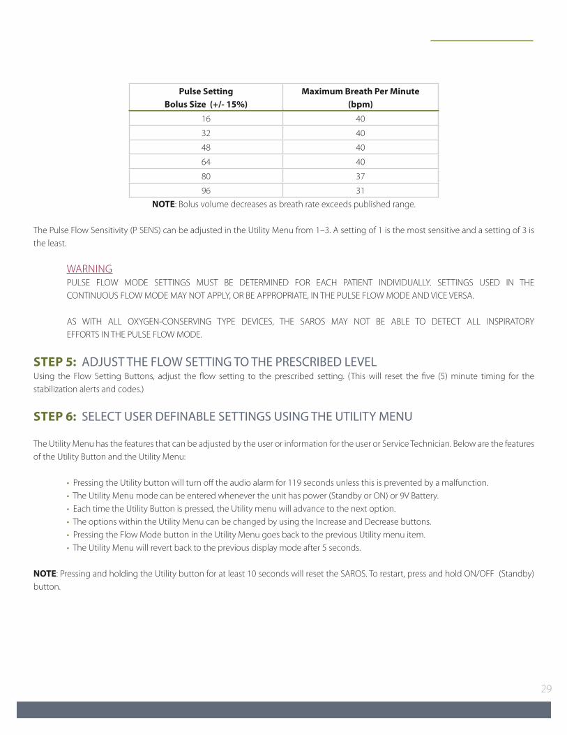
Pulse Setting bolus Size (+/- 15%)
Maximum breath Per Minute (bpm)
16 40
32 40
48 40
64 40
80 37
96 31NOTE: Bolus volume decreases as breath rate exceeds published range.
The Pulse Flow Sensitivity (P SENS) can be adjusted in the Utility Menu from 1–3. A setting of 1 is the most sensitive and a setting of 3 is the least.
WARNING PULSE FLOW MODE SETTINGS MUST BE DETERMINED FOR EACH PATIENT INDIVIDUALLY. SETTINGS USED IN THE CONTINUOUS FLOW MODE MAY NOT APPLY, OR BE APPROPRIATE, IN THE PULSE FLOW MODE AND VICE VERSA.
AS WITH ALL OXYGEN-CONSERVING TYPE DEVICES, THE SAROS MAY NOT BE ABLE TO DETECT ALL INSPIRATORY EFFORTS IN THE PULSE FLOW MODE.
STEP 5: ADJUST THE FLOW SETTING TO THE PRESCRIBED LEVELUsing the Flow Setting Buttons, adjust the flow setting to the prescribed setting. (This will reset the five (5) minute timing for the stabilization alerts and codes.)
STEP 6: SELECT USER DEFINABLE SETTINGS USING THE UTILITY MENU
The Utility Menu has the features that can be adjusted by the user or information for the user or Service Technician. Below are the features of the Utility Button and the Utility Menu:
• Pressing the Utility button will turn off the audio alarm for 119 seconds unless this is prevented by a malfunction. • The Utility Menu mode can be entered whenever the unit has power (Standby or ON) or 9V Battery. • Each time the Utility Button is pressed, the Utility menu will advance to the next option. • The options within the Utility Menu can be changed by using the Increase and Decrease buttons. • Pressing the Flow Mode button in the Utility Menu goes back to the previous Utility menu item. • The Utility Menu will revert back to the previous display mode after 5 seconds.
NOTE: Pressing and holding the Utility button for at least 10 seconds will reset the SAROS. To restart, press and hold ON/OFF (Standby) button.

Oxygen System Technical Manual
30
The following sequence of screens shall be displayed on the LCD when the Utility Menu is displayed.
Alarm Codes:Format: AC=XXXXSee Alarm Code Table definitions. When more than one alarm code is present, pressing the Increase key will show the next highest priority code and pressing the Decrease key will show the next lowest priority code.
Pulse Sensitivity Format: P SENS = X (where X is the value of 1 thru 3)
LCD ContrastFormat: LCD CT = X (where X is the value from 1 thru 6)
Normal Mode brightness:Format N BRT = X (where X is 1 thru 6)Selects the LED and LCD backlight Light intensity used in Normal Mode.
Tactical Mode brightness:Format T BRT= X (where X is 0 thru 6)Selects the LED and LCD backlight Light intensity used in Tactical Mode.
Tactical buzzer VolumeFormat: T VOL=X (where X is the value from 0 thru 6)
Tactical Mode On / Off selection:Format: TACT=ON Format: TACT=OFF
9V battery Status: Format: 9V = GOOD Format: 9V = RPLC
Hours of OperationFormat: HR= XXXXX
System Software Part Number and Revision:Format: SPPPP Mm (where SPPPP = System Software Part Number, M = Major Version, and m = minor Version)
Motor Software Part Number and Revision:Format: MPPPP Mm (where MPPPP = Motor Software Part Number, M = Major Version, and m = minor Version)
STEP 7: BEGIN USING THE SAROSNOTE: You will achieve longer operating time on the Battery if you operate in the Pulse Flow Mode.
STEP 8: POWER OFF THE DEVICE Press and hold the “ON/OFF” Standby Button for two (2) seconds to power OFF the SAROS. (SAROS should be run for one (1) hour every month. Run down battery and recharge.)
Store the SAROS in a cool and dry location.
Tactical mode is ONNormal mode is ON
Battery is goodReplace 9v battery

31
ALERTS, ALARMS, AND TROubLESHOOTING TAbLEThe tables show the possible audible and visual alerts and alarms, their conditions and suggest appropriate troubleshooting responses. If you are unsure about any alerts or alarm conditions, or responses please contact an authorized service technician or go to www.sequal.com.
ALARM LEVELS
Type Level Green LED Yellow LED Red LED Audio Alarm LCD Description
High Alarm 0 OFF OFF ON
ON (may shutdown electronics after
10 seconds)
Flashing star replaces T or N
Malfunction
Med Alarm 1 OFF Blink OFF2 beeps every 119
secFlashing star
replaces T or N Attention is required
Low Alarm 2 OFF Blink OFF 1 beep every 119sFlashing star
replaces T or N Attention is required
Status 3 ON OFF OFF OFF NC All OK
NC= NO CHANGE
WARNING AVAILABILITY OF A BACK-UP SOURCE OF OXYGEN IS RECOMMENDED IN CASE OF POWER OUTAGE OR A DEVICE FAILURE. CONSULT YOUR PROVIDER FOR BACK-UP OXYGEN SYSTEM.
DO NOT Ignore Alarms. System will attempt to produce oxygen under fault condition but may not be at purity or flow.
SYSTEM TROubLESHOOTING GuIDE
SYMPTOM PRObAbLE CAuSE REMEDY
SAROS does not power on when ON/Off button
is pressed(constant tone)
No Battery installed Install Battery or plug into external power
Battery is discharged or no external power is present
Plug into external power
Other Contact an authorized Service Technician
No Oxygen
Air Inlet or HEPA Filter Blocked Clean Air Inlet Filter or replace HEPA Filter
Humidifier Check humidifier attachment and tubing
SAROS not ON Power SAROS ON
Tubing or cannula is not properly connected or is kinked
Check tubing, cannula and connections
Other Contact an authorized Service Technician

Oxygen System Technical Manual
32
SYMPTOM PRObAbLE CAuSE REMEDY
Low Oxygen Concentration
Restriction in tubing or humidifierRepair or replace tubing or humidifier. Place your SAROS so there is adequate air flow.
Air Inlet or HEPA Filter restrictedClean air inlet filter or replace HEPA Filter. Place your SAROS so there is adequate air flow.
Inadequate VentilationPlace your SAROS so that there is adequate air flow, i.e. not covered by a blanket or a poncho.
Hot environment Allow SAROS to cool
Other Contact an authorized Service Technician
Low Oxygen flow
Restriction in humidifier or tubing Repair or replace humidifier or tubing
Air Inlet or HEPA Filter Blocked Clean Air Inlet Filter or replace HEPA Filter
Other Contact an authorized Service Technician
No Oxygen delivered in Pulse flow Mode
Tubing/cannula longer than 7 feet (2.1m)
Attach 7 foot (2.1m) tubing/cannula
Humidifier attached Remove humidifier
No inspiration detected Contact an authorized Service Technician
battery Status Gauge never indicates fully charged
Battery is agingContact an authorized Service Technicianto replace Battery
Heat related failures, i.e. Compressor too hot
Ambient condition is too hotPlace unit in cool environment or out of direct sunlight, if possible.
battery will not latch onto SAROS
Battery Latching Pin Release is stuck in the wrong position
Press the Latching Pin Release Button inward to free the latch mechanism and re-install Battery
Oxygen production is limited due to power limitations
External power source cannot supply enough power
Check air inlet filter and check the external power source
SAROS OPTIONAL ACCESSORIESVisit us at www.sequal.com for more information about optional accessories. There are many different types of oxygen tubing, cannula, and humidifiers. The following items are recommended by SeQual Technologies for use with your SAROS.
Salter Labs® Humidifier, Part Number 7600, or equivalent: If an optional humidifier is prescribed, follow the manufacturer’s instructions for use. Attach the humidifier to the oxygen outlet port of the SAROS. Use of optional humidifiers not recommended for the SAROS may impair performance of the device and may void the warranty.
DO NOT use a humidifier in the Pulse Flow Mode. The SAROS will not detect inspiratory effort. The device will alarm and default to the Continuous Flow Mode for continuing operation.
SeQual Technologies Humidifier Adapter – Part Number 3509: If prescribed an optional humidifier is prescribed, use the SeQual Humidifier Adapter. Follow the instructions for use. Attach the Humidifier Adapter to the oxygen outlet port of the SAROS and then to the humidifier.

33
Attach the cannula, or oxygen tubing to the humidifier outlet.Salter Labs Oxygen Supply Tubing, Part Number Series 2000, or equivalent: The internal diameter should be no less than 3/16” (0.48 cm). Connect the oxygen tubing to the outlet port of the humidifier or directly to the oxygen outlet port of the SAROS if you do not use a humidifier. Connect the other end of the tube to the nasal cannula, if oxygen supply tubing is not already attached to the cannula. Tubing not specified for use with this SAROS may impair the performance of the device.
WARNING THE TUBE FITTING MAY BE TIGHT - DO NOT USE OILS OR GREASE TO LUBRICATE TUBING OR OXYGEN OUTLET PORT.
IF TUBING BECOMES DISCONNECTED DURING OPERATION, THE SAROS DOES NOT ALARM. CHECK FLOW AT THE CANNULA TO VERIFY OXYGEN DELIVERY.
Salter Labs Oxygen Cannula, Part Number 1600 Series, or equivalent: A cannula is typically used to deliver oxygen to the patient. In most cases they are already attached to the oxygen tubing. If not, follow the instructions included with the cannula to attach it to the oxygen tubing. Use of an oxygen cannula not specified for use with this SAROS may impair the performance of the device.
WARNING USE OF AN OXYGEN MASK IS CONTRAINDICATED DUE TO THE POSSIBILITY OF REBREATHING EXHALED CARBON DIOXIDE.
CLEANING, CARE AND ROuTINE MAINTENANCE
ROUTINE MAINTENANCE
• Servicing of the internal components of this device must be conducted by a trained and qualified service technician.
• A qualified technician will perform inspections and maintenance of the ATF compressor, PCB set, alarms, internal 9 volt battery, Battery and other parts every six (6) months or as needed, whichever comes first.
• Operate the device once a month by running the device on battery power until drained. Plug in to recharge while operating or off.
WARNING DO NOT DISASSEMBLE THE SAROS OR ATTEMPT TO PERFORM ANY MAINTENANCE TASKS OTHER THAN THOSE DESCRIBED IN THE USER CARE AND CLEANING OF THE DEVICE SECTION BELOW. DISASSEMBLING THE SAROS MAY CREATE AN ELECTRICAL SHOCK HAZARD AND WILL VOID YOUR WARRANTY. CONTACT A QUALIFIED TECHNICIAN FOR ANY INSPECTION, MAINTENANCE, OR REPAIR REQUIRED.
USER CARE AND CLEANING OF THE DEVICE
Cannula Replacement: Clean and Replace your supply tubing and cannula on a regular basis as recommended by the manufacturer’s instructions.
Air Inlet filter: Check daily and clean once a week. Ambient air is drawn into the device through the air inlet located on the top of the device. Cleaning the air inlet filter is the most important maintenance activity to keep the SAROS performing properly. Check this air inlet filter daily and clean it at least once a week using the following procedure: 1. Remove the four screws on the Cover on the top of the device and remove the air inlet filter; 2. Wash the filter in warm tap water;

Oxygen System Technical Manual
34
3. Allow the filter to air dry; 4. Reinsert the filter in the location it was removed; 5. Cleaning tip - keep a clean second filter as a replacement for use when one filter is drying.
CAUTION THE AIR INLET FILTER SHOULD BE FREE OF LIQUID WATER AND DRY TO THE TOUCH BEFORE REINSTALLATION. EXCESS MOISTURE IN THE FILTER MAY IMPAIR THE PROPER OPERATION OF THE SAROS.
The air inlet filter should be replaced as needed. If the SAROS is used in a dusty environment, the filter may need to be replaced or cleaned more often.
AC Power Adapter, 24 VDC Cable and Power Cord: Turn OFF the SAROS and disconnect from AC or DC power before any cleaning or disinfection activity. Use a damp (not soaking wet) cloth or sponge. Spray the cloth or sponge with a mild detergent solution to clean the exterior and power supplies. To disinfect the SAROS use Lysol® Brand II disinfectant. Proceed as directed by the manufacturer.
WARNING UNPLUG POWER CORDS, AC OR DC POWER SUPPLIES BEFORE CLEANING THE EXTERIOR.
DO NOT USE DENATURED ALCOHOL OR APPLY LIQUID SPRAY OR AEROSOL CLEANERS TO THE CORDS OR POWER SUPPLIES.
Optional Humidifier: If used, clean the humidifier daily to reduce the possibility of contamination. Follow the cleaning recommendations by the manufacturer of the humidifier. Replace the humidifier monthly, or as recommended by the manufacturer.
bATTERY CLEANING, CARE AND MAINTENANCE
The Battery in the SAROS requires special care to assure a longer life and the highest level of performance. The SeQual Battery is the only approved Battery recommended for use with the SAROS.
Use a damp (not soaking wet) cloth or sponge. First spray the cloth or sponge with a mild detergent and then clean the Battery case and the latch.
battery Disposal: Your Battery is rechargeable and can be recycled. Always return it to an authorized service center or SeQual Technologies for proper disposal. You can also contact your local city or town offices for instructions on proper disposal of the Battery.
battery Storage: Your Battery should be stored in a cool and dry location.
SHIPPING AND TRANSPORTING THE SAROS
When shipping the SAROS use original packaging if possible. Always remove the Battery from the SAROS before shipping.
If original packaging material is available repack the SAROS, Battery and power supplies in the designated packaging area.
If original packaging material or other SeQual authorized shipping container is not available, contact SeQual for replacement shipping container.

35
STORING THE SAROS
Heat and humidity may degrade the performance or severely damage the SAROS. Store the device in a cool, dry protected area away from high temperatures, moisture and humidity. Remove the Battery when storing the device.
DISCARDING THE SAROS
SAROS bATTERY: Contact the local city, town or country offices for instructions on proper disposal of the Battery. Alternately, SeQual may be contacted for the Battery disposal.
SAROS: Local environmental laws may prohibit disposal of electrical and/or electronic equipment such as the SAROS and AC Power Adapter. Contact the local city, town or country offices for instructions on proper disposal of electrical or electronic equipment. Alternately, SeQual may be contacted for disposal information.
ALARM INDICATIONS AND CODES
This table is arranged accordingly to alarm priority.
Description Level Audio indicator
Ext. Power LED
battery Icon Alarm Code Description
External voltage too high 0 ON Blink NC AC00
This alarm shall activate when the external voltage is greater than 32V. O2 production and battery charging
shall not begin and the electronics shall shut down after 10 seconds.
Loss of Power 0 ON NC NC 4000
This alarm shall activate during production when the system determines that valid power has been lost. O2 production and battery charging shall stop, and the
electronics shall shut down after 10 seconds.
Missing Power 0 ON NC NC 4010
This alarm shall activate if the user attempts to start the unit while there is no usable power source connected. O2 production and battery charging shall not begin and the
electronics shall shut down after 10 seconds.
Compressor Too Hot 0 ON NC NC 9100 O2 production shall stop or cannot be started.
Power Board Too Hot 0 ON NC NC 9200
O2 production and battery charging shall stop or cannot be started. The electronics shall shut down after 10
seconds when on battery power. The display shall be blanked after 10 seconds when on external power.
Motor Driver Board Too Hot
0 ON NC NC 9300O2 production and battery charging shall stop or cannot
be started.
IPC Failure 0 ON NC NCA000A010
O2 production and battery charging shall stop or cannot be started. The electronics shall shut down after 10
seconds when on battery power. The display shall be blanked after 10 seconds when on external power.
%02 < 70% 0 ON NC NC 0400
The alarm shall activate only when concentration has been less than 70% for more than 60 seconds. It shall
clear immediately if the concentration goes above 70%.The unit shall continue production.
Ultrasonic Failure 0 ON NC NC A300 O2 production shall stop or cannot be started.
Motor Controller Fails Post 0 ON NC NC FD00 O2 production shall not be started.
Compressor Stall 0 ON NC NC 9194 O2 production shall stop or cannot be started.
Compressor Driver Fault 0 ON NC NC 9195 O2 production shall stop or cannot be started.

Oxygen System Technical Manual
36
Description Level Audio indicator
Ext. Power LED
battery Icon Alarm Code Description
Compressor Temperature Sensor Failure
0 ON NC NC 9110 O2 production shall continue.
ATF Temperature Sensor Failure
0 ON NC NC 8900 O2 production shall continue.
Compressor and ATF Temperature Sensor Failure
0 ON NC NC91108900
O2 production shall stop or not be started depending on Compressor Temperature Sensor and ATF Temperature
Sensor condition.
Ambient Pressure Sensor Failure
0 ON NC NC AB00 O2 production shall continue.
Product Temperature Sensor Failure
0 ON NC NC A400 O2 production shall continue.
Ambient Temperature Sensor Failure
0 ON NC NC AB10 O2 production shall continue.
Product and Ambient Temperature Sensor Failure
0 ON NC NCA410AB10
O2 production shall stop or not be started depending on Product Temperature Sensor and Ambient Temperature
Sensor condition.
Unable to Achieve or Maintain Product Tank
Pressure0 ON NC NC A500 O2 production shall stop.
Purity Calibration Data Failure
0 ON NC NC A600 The unit shall produce using default data.
Flow Calibration Data Failure 0 ON NC NC A700 The unit shall produce using default data.
Watchdog Timeout 0 ON NC NC 9000
O2 production and battery charging shall stop or cannot be started. The electronics shall shut down within 15 seconds when on battery power. The display shall be blanked within 15 seconds when on external power.
Invalid Reset 0 ON NC NC 8000
O2 production and battery charging shall not start. The electronics shall shut down within 15 seconds when on
battery power. The display shall be blanked within 15 seconds when on external power.
I/O Port Failure 0 ON NC NC 8100
O2 production and battery charging shall not start. The electronics shall shut down within 15 seconds when on
battery power. The display shall be blanked within 15 seconds when on external power.
RAM Failure 0 ON NC NC 8200
O2 Production and battery charging shall stop. The electronics shall shut down within 15 seconds when on
battery power. The display shall be blanked within 15 seconds when on external power.
Program Memory Failure 0 ON NC NC 8310
O2 Production and battery charging shall stop. The electronics shall shut down within 15 seconds on when on battery power. The display shall be blanked within 15
seconds when on external power.
Battery Too Hot 0 OFF NCNo
Waterfall9510 Battery shall not be charged or discharged.
SSI Requested Alarm High 0 ON NC NC F000 This is an alarm test and shall not affect operation.
Pulse Mode Disabled 12 beeps every
119sNC NC A200
This alarm shall activate when a breath sensor malfunction is detected. The system shall not enter pulse
mode.
Battery Communication Error
12 beeps every
119sBlink Blink 9500 Battery shall not be charged or discharged.
Battery Too Hot to Charge 1 N/A OFFNo
WaterfallNone The battery shall not be charged.

37
Description Level Audio indicator
Ext. Power LED
battery Icon Alarm Code Description
Battery Too Cold to Use 1 OFF OFFNo
Waterfall95C0 The battery shall not be charged or discharged.
Battery Too Cold to Charge 1 NA OFFNo
WaterfallNone The battery shall not be charged.
Flow Rate Error 12 beeps
every 119sNC NC 2000
The alarm shall activate when the difference between the desired flow rate and the measured flow rate exceeds
10% for a minimum duration of 60 seconds.
Cannot Charge Battery 12 beeps every
119sNC Blink 952C
This alarm shall activate if system is attempting to charge the battery, but can’t detect battery current.
Low Battery 12 beeps every
119sNC Blink 9540
The alarm shall activate when the time remaining on battery is ≤ 6 minutes. The alarm shall cease when the
time remaining is ≥12 minutes.
70%< O2 <85% 12 beeps every
119sNC NC 0800
The alarm shall activate only when concentration has been less than 85% for more than 60 seconds. It shall
clear immediately if the concentration goes above 85%.
Key Stuck On 12 beeps every
119sNC NC 8110
This alarm shall activate when a key is active for greater than 7 seconds. A stuck Utility Key cannot activate this
alarm.
Run Log Storage Failure 12 beeps every
119sNC NC 8300
Production shall continue. Battery charging if required shall continue.
Breath Pressure Sensor Failure
12 beeps every
119sNC NC A210
The alarm shall activate when a breath pressure sensor failure.
Power Board Thermistor Failure
12 beeps every
119sNC NC 9210
Production shall continue. Battery charging if required shall continue.
Motor Driver Board Thermistor Failure
12 beeps every
119sNC NC 9310
Production shall continue. Battery charging if required shall continue.
Battery Thermistor failure 12 beeps
every 119sNC Blink 9550
The system shall not use the battery if the reported independent battery thermistor value is
>433K or <222K.
Battery Chip Thermistor failure
12 beeps every
119sNC Blink 9560
The system shall not use the battery if the reported battery chip thermistor value is >433K or <250K.
EEPROM Data Write Failure 12 beeps every
119sNC NC 8400
Production shall continue. Battery charging if required shall continue.
Event Log Storage Failure 12 beeps
every 119sNC NC 8320
Production shall continue. Battery charging if required shall continue.
SSI Requested Alarm Medium
12 beeps
every 119sNC NC F100 This is an alarm test and shall not affect operation.
All OK 3 OFF NC NC None This indication shall exist when no alarms are detected.
Initialization 3 OFF NC NC NonePurity alarms shall be inhibited during the initialization
period.
DO NOT Ignore Alarms. System will attempt to produce oxygen under fault condition but may not be at purity or flow.

Manufactured by:SeQual Technologies Inc.
2200 Airport Industrial DriveSuite 500
Ball Ground, GA 30107 USA1-800-482-2473
Worldwide: www.sequal.com
SeQual® and autoSAT® are trademarks of CHART SeQual Technologies Inc. Ball Ground, GA 30107.Salter Labs® is a registered mark of Salter Labs, Arvin, CA 92303.
Lysol® is a registered trademark of Reckitt Benckiser, UK.
PN 9705 Rev.C