Sentinel Operator Manual (S/N 000000-010999) - Choose …€¦ · · 2018-04-01TACHOMETER 36........
139
*331000* 331000 Rev. 13 (3-2018) SENTINEL R Sweeper Operator Manual Machine Serial Number Range (S/N 000000−010999) Tennant True R Parts North America / International For latest Parts manual or other language Operator manual, visit: www.tennantco.com/manuals
-
Upload
truongnguyet -
Category
Documents
-
view
215 -
download
1
Transcript of Sentinel Operator Manual (S/N 000000-010999) - Choose …€¦ · · 2018-04-01TACHOMETER 36........

*331000*
331000Rev. 13 (3-2018)
SENTINEL�
SweeperOperator Manual
Machine Serial Number Range
(S/N 000000−010999)
TennantTrue� Parts
North America / InternationalFor latest Parts manual or otherlanguage Operator manual, visit:
www.tennantco.com/manuals

INTRODUCTION
This manual is furnished with each new model. It provides necessary operation and maintenance instructions.
Read this manual completely and understand the machine before operating or servicing it.
This machine will provide excellent service. However, the best results will be obtained at minimum costs if:
� The machine is operated with reasonable care.
� The machine is maintained regularly - per the machine maintenance instructions provided.
� The machine is maintained with manufacturer supplied or equivalent parts.
PROTECT THE ENVIRONMENTPlease dispose of packaging materials,old machine components and fluids inan environmentally safe way accordingto local waste disposal regulations.
Always remember to recycle.
Model No. −
Serial No. −
Installation Date −
Please fill out at time of installation for future reference.MACHINE DATA
Tennant CompanyPO Box 1452Minneapolis, MN 55440Phone: (800) 553−8033www.tennantco.com
CALIFORNIA PROPOSITION 65 WARNING: Engine exhaust from this product contains chemicals known to the State of California to cause cancer,birth defects, or other reproductive harm.
Thermo−Sentry, Total View and Vario Sweeping Brush are trademarks of Tennant Company.
Specifications and parts are subject to change without notice.
Original instructions, Copyright � 2003, 2005−2010, 2013 − 2016, 2018 TENNANT, Printed in U.S.A.

CONTENTS
1Sentinel 331000 (5−10)
CONTENTS
PageSAFETY PRECAUTIONS 4. . . . . . . . . . . . . . . .OPERATION 8. . . . . . . . . . . . . . . . . . . . . . . . . . .
OPERATOR RESPONSIBILITY 8. . . . . . . .MACHINE COMPONENTS 9. . . . . . . . . . . .CONTROL PANEL SYMBOLS 10. . . . . . . . .CONTROLS AND INSTRUMENTS 12. . . . .OPERATION OF CONTROLS 17. . . . . . . . .
OPERATOR SEAT 17. . . . . . . . . . . . . . . . .SEAT BELTS 17. . . . . . . . . . . . . . . . . . . . .STEERING WHEEL 18. . . . . . . . . . . . . . .STEERING WHEEL TILT LEVER
(For machines serial number 007053 and below) 18. . . . . . . . . . .
STEERING WHEEL TILT LEVER (For machines serial number
007054 and above) 18. . . . . . . . . . .PARKING LIGHTS, HEADLIGHTS,
BRIGHT HEADLIGHTS, SIGNAL, AND HORN SWITCH 19. . . . . . . . . . .
WINDSHIELD WIPER AND WASHER SWITCH 19. . . . . . . . . . . . .
IGNITION SWITCH (For machines serial number 007709 and below) 20.
IGNITION SWITCH (For machines serial number 007710 and above) 20.
PROPELLING PEDAL 20. . . . . . . . . . . . .BRAKE PEDAL 21. . . . . . . . . . . . . . . . . . .ACCESSORY POWER SOCKET 21. . . .DIRECTIONAL LEVER 21. . . . . . . . . . . . .THROTTLE LEVER 22. . . . . . . . . . . . . . . .VARIO SWEEPING BRUSH LOCK PIN
(OPTION) 22. . . . . . . . . . . . . . . . . . . . .VARIO SWEEPING BRUSH
TILT/ARM SWITCH (OPTION) 22. . .VARIO SWEEPING BRUSH
JOYSTICK (OPTION) 23. . . . . . . . . . .VARIO SWEEPING BRUSH
ON−OFF SWITCH (OPTION) 24. . . .VARIO SWEEPING BRUSH
RAISE−LOWER SWITCH (OPTION) 24. . . . . . . . . . . . . . . . . . .
BRIGHT HEADLIGHTS LIGHT 25. . . . . .PARKING BRAKE LIGHT 25. . . . . . . . . . .SIGNAL LIGHT 25. . . . . . . . . . . . . . . . . . .GLOW PLUG LIGHT 26. . . . . . . . . . . . . . .CLOGGED ENGINE AIR FILTER
LIGHT 26. . . . . . . . . . . . . . . . . . . . . . . . .WATER TANK LOW LIGHT (OPTION) 26VACUUM WAND DOOR LIGHT
(OPTION) 27. . . . . . . . . . . . . . . . . . . . .HOPPER OVERLOAD LIGHT 27. . . . . . .HEATER KNOB 27. . . . . . . . . . . . . . . . . . .FAN KNOB 28. . . . . . . . . . . . . . . . . . . . . . .AIR CONDITIONER KNOB (OPTION) 28
PageAIR CIRCULATION VENTS 28. . . . . . . . .LOW BRAKE PRESSURE LIGHT 29. . .INCLINE LIGHT (High Dump Model) 29.ENGINE SHUTDOWN
OVERRIDE SWITCH 30. . . . . . . . . . . .PARKING BRAKE SWITCH 30. . . . . . . . .LEFT SIDE BRUSH WATER VALVE
KNOB (OPTION) 31. . . . . . . . . . . . . . .VARIO SWEEPING BRUSH LEFT
WATER VALVE KNOB (OPTION) 31.VARIO SWEEPING BRUSH RIGHT
WATER VALVE KNOB (OPTION) 32.RIGHT SIDE BRUSH WATER
VALVE KNOB (OPTION) 32. . . . . . . .FUSES 33. . . . . . . . . . . . . . . . . . . . . . . . . . .ENGINE WATER TEMPERATURE
GAUGE 34. . . . . . . . . . . . . . . . . . . . . . .FUEL LEVEL GAUGE 34. . . . . . . . . . . . . .ENGINE OIL PRESSURE GAUGE 34. .VOLTMETER 35. . . . . . . . . . . . . . . . . . . . .HOURMETER 35. . . . . . . . . . . . . . . . . . . .ODOMETER 35. . . . . . . . . . . . . . . . . . . . . .SPEEDOMETER 35. . . . . . . . . . . . . . . . . .TACHOMETER 36. . . . . . . . . . . . . . . . . . .SWITCH PANEL 37. . . . . . . . . . . . . . . . . .HOPPER TILT BACK SWITCH 37. . . . . .HOPPER TILT FORWARD SWITCH 37.HOPPER LIFT SWITCH
(High Dump Model) 38. . . . . . . . . . . . .HOPPER LOWER SWITCH
(High Dump Model) 38. . . . . . . . . . . . .HOPPER DOOR OPEN SWITCH 39. . . .HOPPER DOOR CLOSE SWITCH 39. .WATER PUMP SWITCH (OPTION) 39. .LEFT SIDE BRUSH SWITCH
(OPTION) 40. . . . . . . . . . . . . . . . . . . . .RIGHT SIDE BRUSH SWITCH 40. . . . . .FILTER SHAKER SWITCH 40. . . . . . . . .CONVEYOR REVERSE SWITCH 41. . .VACUUM FAN SWITCH 41. . . . . . . . . . . .SWEEP SWITCH 42. . . . . . . . . . . . . . . . . .4-WAY WARNING LIGHTS SWITCH 43.HAZARD LIGHT SWITCH 43. . . . . . . . . .SIDE BRUSH SPOT LIGHT(S)
SWITCH 43. . . . . . . . . . . . . . . . . . . . . . .REAR NIGHT SWEEPING LIGHT
SWITCH (OPTION) 44. . . . . . . . . . . . .FRONT NIGHT SWEEPING LIGHT
SWITCH (OPTION) 44. . . . . . . . . . . . .HIGH PRESSURE WASHER SWITCH
(OPTION) 44. . . . . . . . . . . . . . . . . . . . .DOME AND MAP LIGHT SWITCH 45. . .RADIO AND COMPACT DISK PLAYER
(OPTION) 45. . . . . . . . . . . . . . . . . . . . .LATCHES 45. . . . . . . . . . . . . . . . . . . . . . . .

CONTENTS
Sentinel 331000 (5−10)2
PageTRAFFIC ADVISOR SIGNAL LIGHT
SWITCH (OPTION) 46. . . . . . . . . . . . .TRAFFIC ADVISOR SIGNAL LIGHT
FUNCTION KNOB (OPTION) 46. . . .HOPPER SUPPORT PIN 47. . . . . . . . . . .HOPPER SUPPORT BAR
(High Dump Model) 48. . . . . . . . . . . . .HOW THE MACHINE WORKS 49. . . . . . . . .PRE-OPERATION CHECKLIST 50. . . . . . . .STARTING THE MACHINE 51. . . . . . . . . . . .SWEEPING AND BRUSH INFORMATION 54SWEEPING 55. . . . . . . . . . . . . . . . . . . . . . . . .STOP SWEEPING 59. . . . . . . . . . . . . . . . . . .EMPTYING THE HOPPER 61. . . . . . . . . . . .STOP THE MACHINE 65. . . . . . . . . . . . . . . .POST-OPERATION CHECKLIST 67. . . . . . .ENGAGING HOPPER SUPPORT PIN 68. .DISENGAGING HOPPER SUPPORT PIN 70ENGAGING HOPPER SUPPORT BAR
(High Dump Model) 71. . . . . . . . . . . . . . . .DISENGAGING HOPPER SUPPORT BAR
(High Dump Model) 73. . . . . . . . . . . . . . . .OPERATION ON INCLINES 74. . . . . . . . . . .OPTIONS 75. . . . . . . . . . . . . . . . . . . . . . . . . . .
VARIO SWEEPING BRUSH 75. . . . . . . .WET DUST CONTROL SYSTEM 77. . . .VACUUM WAND 79. . . . . . . . . . . . . . . . . .CAB JACK 82. . . . . . . . . . . . . . . . . . . . . . . .TILTING THE CAB (MANUALLY) 84. . . .
MACHINE TROUBLESHOOTING 86. . . . . .MAINTENANCE 88. . . . . . . . . . . . . . . . . . . . . . . .
MAINTENANCE CHART 89. . . . . . . . . . . . . .LUBRICATION 91. . . . . . . . . . . . . . . . . . . . . . .
A. HOPPER TILT (LOW DUMP) 92. . . .B. HOPPER LIFT/TILT (HIGH
DUMP OPTION) 92. . . . . . . . . . . . . . . .C. AXLE LEAF SPRINGS 92. . . . . . . . . .D. STEERING CYLINDER 93. . . . . . . . .E. WHEEL PIVOTS POINTS 93. . . . . . .F. SIDE BRUSH PIVOT 93. . . . . . . . . . . .G. VARIO SWEEPING BRUSH
(OPTION) 94. . . . . . . . . . . . . . . . . . . . .H. CONVEYOR BEARINGS 94. . . . . . . .I. CONVEYOR CHAIN 95. . . . . . . . . . . . .J. ENGINE 95. . . . . . . . . . . . . . . . . . . . . . .K. DIFFERENTIAL 96. . . . . . . . . . . . . . . .L. MAIN BRUSH SUPPORT RODS 96.
HYDRAULICS 97. . . . . . . . . . . . . . . . . . . . . . .HYDRAULIC FLUID RESERVOIR 97. . .REPLACING HYDRAULIC FLUID
FILTER 98. . . . . . . . . . . . . . . . . . . . . . . .HYDRAULIC FLUID 99. . . . . . . . . . . . . . .HYDRAULIC HOSES 100. . . . . . . . . . . . . .PURGING AIR FROM THE
HYDRAULIC CONVEYOR LIFT SYSTEM 100. . . . . . . . . . . . . . . . . . .
PageENGINE 101. . . . . . . . . . . . . . . . . . . . . . . . . . . .
COOLING SYSTEM 101. . . . . . . . . . . . . . .AIR FILTER 102. . . . . . . . . . . . . . . . . . . . . . .AIR INTAKE SCREEN 103. . . . . . . . . . . . .FUEL FILTER 103. . . . . . . . . . . . . . . . . . . . .FUEL WATER SEPARATOR 103. . . . . . . .FUEL LINES 104. . . . . . . . . . . . . . . . . . . . . .ENGINE VALVE 104. . . . . . . . . . . . . . . . . . .
CAB FILTERS 105. . . . . . . . . . . . . . . . . . . . . . .WET DUST CONTROL FILTER
(OPTION) 105. . . . . . . . . . . . . . . . . . . . . . . .WINDSHIELD WIPER BLADES 106. . . . . . . .WINDSHIELD WASHER FLUID 106. . . . . . . .
BATTERY 106. . . . . . . . . . . . . . . . . . . . . . . .BELTS AND CHAINS 107. . . . . . . . . . . . . . . . .
ALTERNATOR/FAN BELTS 107. . . . . . . . .AIR CONDITIONER BELT (OPTION) 107STATIC DRAG CHAIN 107. . . . . . . . . . . . .
DEBRIS HOPPER 108. . . . . . . . . . . . . . . . . . . .HOPPER DUST FILTER 108. . . . . . . . . . . .
TO CLEAN THE HOPPER DUST FILTER 108. . . . . . . . . . . . . . .
TO REMOVE OR REPLACE HOPPER DUST FILTER 108. . . . . .
THERMO SENTRY 109. . . . . . . . . . . . . . . .CONVEYOR 110. . . . . . . . . . . . . . . . . . . . . . . . .BRUSHES 111. . . . . . . . . . . . . . . . . . . . . . . . . . .
MAIN BRUSH 111. . . . . . . . . . . . . . . . . . . . .TO REPLACE MAIN BRUSH 111. . . . .TO CHECK AND ADJUST MAIN
BRUSH PATTERN 114. . . . . . . . . . .SIDE BRUSH 115. . . . . . . . . . . . . . . . . . . . .
TO REPLACE SIDE BRUSH 115. . . . .SKIRTS AND SEALS 116. . . . . . . . . . . . . . . . .
BRUSH ACCESS DOOR SKIRTS 116. . .DRY DUST CONTROL SKIRTS
(OPTION) 116. . . . . . . . . . . . . . . . . . . . .BRUSH COMPARTMENT REAR
SKIRT 116. . . . . . . . . . . . . . . . . . . . . . . . .CONVEYOR SKIRTS 117. . . . . . . . . . . . . .DOOR SEALS 117. . . . . . . . . . . . . . . . . . . .CONVEYOR SEALS 118. . . . . . . . . . . . . . .HOPPER SEALS 118. . . . . . . . . . . . . . . . . .
SKIDS 119. . . . . . . . . . . . . . . . . . . . . . . . . . . . . .BRAKES AND TIRES 119. . . . . . . . . . . . . . . . .
SERVICE BRAKES 119. . . . . . . . . . . . . . . .PARKING BRAKE 119. . . . . . . . . . . . . . . . .TIRES 120. . . . . . . . . . . . . . . . . . . . . . . . . . .WHEEL ALIGNMENT 120. . . . . . . . . . . . . .WHEEL NUTS 120. . . . . . . . . . . . . . . . . . . .
PUSHING, TOWING, AND TRANSPORTING THE MACHINE 121. . .PUSHING OR TOWING THE
MACHINE 121. . . . . . . . . . . . . . . . . . . . .TRANSPORTING THE MACHINE 122. . . . . .MACHINE JACKING 124. . . . . . . . . . . . . . . . . .

CONTENTS
3Sentinel 331000 (5−10)
PageSTORING MACHINE 125. . . . . . . . . . . . . . . . .
FREEZE PROTECTION FOR WET DUST CONTROL SYSTEM 125. . . . . .
FREEZE PROTECTION FOR THE HIGH PRESSURE WASHER OPTION 125. . . . . . . . . . . . . . . . . . . . . . .
SPECIFICATIONS 126. . . . . . . . . . . . . . . . . . . . . .GENERAL MACHINE
DIMENSIONS/CAPACITIES 126. . . . . . . .GENERAL MACHINE PERFORMANCE 127.HYDRAULIC SYSTEM 127. . . . . . . . . . . . . . . .POWER TYPE (S/N 000000−008499) 127. . .POWER TYPE (S/N 008500− ) 128. . . .STEERING 128. . . . . . . . . . . . . . . . . . . . . . . . . .BRAKING SYSTEM 128. . . . . . . . . . . . . . . . . .TIRES 128. . . . . . . . . . . . . . . . . . . . . . . . . . . . . .MACHINE DIMENSIONS 129. . . . . . . . . . . . . .
INDEX 130. . . . . . . . . . . . . . . . . . . . . . . . . . . . . . . . .

SAFETY PRECAUTIONS
Sentinel 331000 (2−2016)4
SAFETY PRECAUTIONS
The following precautions are used throughoutthis manual as indicated in their description:
WARNING: To warn of hazards orunsafe practices which could result insevere personal injury or death.
FOR SAFETY: To identify actions whichmust be followed for safe operation ofequipment.
The machine is suited to sweep disposabledebris. Do not use the machine other thandescribed in this Operator Manual.
The following information signals potentiallydangerous conditions to the operator orequipment:
FOR SAFETY:1. Do not operate machine:
− Unless trained and authorized.− Unless operation manual is read and
understood.− Under the influence of alcohol or
drugs.− While using a cell phone or other
types of electronic devices.− Unless mentally and physically
capable of following machineinstructions.
− If it is not in proper operatingcondition.
− In areas where flammablevapors/liquids or combustible dustsare present.
− In areas that are too dark to safely seethe controls or operate the machineunless operating / headlights areturned on.
− In flammable or explosive areas unlessdesigned for use in those areas.
2. Before starting machine:− Check for fuel leaks.− Keep sparks and open flame away
from refueling area.− Make sure all safety devices are in
place and operate properly.− Check brakes and steering for proper
operation.− Adjust seat and fasten seat belt.
3. When starting machine:− Keep foot on brake and directional
pedal in neutral.
4. When using machine:− Use only as described in this manual.− Do not pick up burning or smoking
debris, such as cigarettes, matches orhot ashes.
− Use brakes to stop machine.− Reduce speed when turning.− Keep all parts of body inside operator
station while machine is moving.− Always be aware of surroundings
while operating machine.− Use care when reversing machine.− Move machine with care when hopper
is raised.− Make sure adequate clearance is
available before raising hopper.− Do not raise hopper when machine is
on an incline.− Keep children and unauthorized
persons away from machine.− Go slow on inclines and slippery
surfaces.− Use care when reversing machine.− Do not carry riders on machine.− Always follow safety and traffic rules.− Report machine damage or faulty
operation immediately.
5. Before leaving or servicing machine:− Do not park near combustible
materials, dust, gases, or liquids.− Stop on level surface.− Set parking brake.− Turn off machine and remove key.
6. When servicing machine:− Avoid moving parts. do not wear loose
jackets, shirts, or sleeves.− Block machine tires before jacking
machine up.− Jack machine up at designated
locations only. Block machine up withjack stands.
− Use hoist or jack that will support theweight of the machine.
− Do not push or tow the machinewithout an operator in the seatcontrolling the machine.
− Do not power spray or hose offmachine near electrical components.
− Wear eye and ear protection whenusing pressurized air or water.
− Disconnect battery connections beforeworking on machine.
− Avoid contact with battery acid.− Avoid contact with hot engine coolant.− Do not remove cap from radiator when
engine is hot.

SAFETY PRECAUTIONS
5Sentinel 331000 (2−2016)
− Allow engine to cool.− Keep flames and sparks away from
fuel system service area. Keep areawell ventilated.
− Use cardboard to locate leakinghydraulic fluid under pressure.
− All repairs must be performed bytrained personnel.
− Do not modify the machine from itsoriginal design.
− Use Tennant supplied or approvedreplacement parts.
7. When loading/unloading machineonto/off truck or trailer:− Turn off machine.− Use truck or trailer that will support
the weight of the machine.− Use winch. Do not drive the machine
onto/off the truck or trailer unless theload height is 380 mm (15 in) or lessfrom the ground.
− Set parking brake after machine isloaded.
− Block machine tires.− Tie machine down to truck or trailer.− Wear personal protective equipment
as needed and where recommended inthis manual.
8. When loading/unloading machineonto/off truck or trailer:− Empty debris hopper before loading
machine.− Turn off machine and remove key.− Use ramp, truck or trailer that will
support the weight of the machine andoperator.
− Do not load/unload on ramp inclinesthat exceed 11% grade.
− Use winch. Do not drive the machineonto/off the truck or trailer unless theload height is 380 mm (15 in) or lessfrom the ground.
− Set parking brake (if equipped) aftermachine is loaded.
− Block machine tires.− Tie machine down to truck or trailer.
WARNING: Machine can emit excessivenoise. Consult with your regulatoryagency for exposure limits. Hearing losscan result. Wear hearing protection.
WARNING: Raised hopper may fall.Engage hopper support bar.
WARNING: Raised hopper may fall.Engage hopper support pin.
WARNING: Brush linkage pinch points.Stay clear when linkage is moving.
WARNING: Side brush can move. Donot step on side brush.
WARNING: Hopper door pinch point.Stay clear of hopper door.
WARNING: High dump verticalclearance. Stay clear of overheadobstructions and power lines.
WARNING: Conveyor throws debris.Conveyor pinch point. Stay clear whenin operation.
WARNING: Flammable materials cancause explosion or fire. Do not useflammable materials in tank. Only usewater.
WARNING: Engine emits toxic gases.Severe respiratory damage orasphyxiation can result. Provideadequate ventilation. Consult with yourregulatory agency for exposure limits.Keep engine properly tuned.
WARNING: Lift arm pinch point. Stayclear of hopper lift arms.
WARNING: Raised cab may fall. Engagecab support bar.
WARNING: Do not spray people oranimals. Severe personal injury canresult. Wear eye protection. Holdsprayer with two hands.
Warning: This product containschemicals known to the state ofCalifornia to cause cancer, birth defects,or other reproductive harm.

SAFETY PRECAUTIONS
Sentinel 331000 (3−2015)6
The following safety labels are mounted on themachine in the locations indicated. If these or anylabel becomes damaged or illegible, install a newlabel in its place.
BRUSH LINKAGE LABEL (VARIO SWEEPING BRUSH) − Located on the front of the machine.
HIGH DUMP LABEL − Located on the upper console.EMISSIONS LABEL −
Located on the upper console.
354168
FOR SAFETY LABEL − Located on the upper console.
SIDE BRUSH LABEL − Located above the side brush(es).
HOPPER DOOR LABEL − Located below the hopper door.
RAISED CAB LABEL − Located below the cab on the frame.
HIGH PRESSURESPRAY HAZZARDLABEL − Locatedon the frame ofmachine.

SAFETY PRECAUTIONS
7Sentinel 331000 (3−2015)
HOPPER SUPPORT BAR LABEL (High Dump) − Located on bothsides of the support bar, on therear center of the hopper lift, andon both sides of the hopper lift.
VACUUM WAND OPTION NOISELABEL − Located on the vacuum wand.
CONVEYOR LABEL − Located at the back of the conveyor.
354168
FLAMMABLE MATERIALS LABEL(Wet Dust Control Option) − Located on the drivers sidebelow the water fill spout.
HOPPER SUPPORT PIN LABEL −Located on both sides of the support pin.On low dump models, one is located onthe upper support cylinder.On high dump models, one is located onthe drivers side of the hopper lift.
LIFT ARMS LABEL (High Dump) −Located on the side of the hopper lift.
OPERATION
Sentinel 331000 (6−03)8
OPERATION
OPERATOR RESPONSIBILITY
� The operator’s responsibility is to take careof the daily maintenance and checkups ofthe machine to keep it in good workingcondition. The operator must inform theservice mechanic or supervisor when therequired maintenance intervals occur asstated in the MAINTENANCE section of thismanual.
� Read this manual carefully before operatingthis machine. View the operation videosupplied with the machine.
FOR SAFETY: Do not operate machine,unless operation manual is read andunderstood.
� Check the machine for shipping damage.Check to make sure machine is completeper shipping instructions.
� Keep your machine regularly maintained byfollowing the maintenance information in thismanual. We recommend taking advantageof a regularly scheduled service contractfrom your TENNANT representative.
� Order parts and supplies directly from yourauthorized TENNANT representative. Usethe parts manual provided when orderingparts.
� The model SENTINEL has a GVWR of 9072kg (20,000 lb) or 4536 kg (10,000 lb) peraxle. Operate only on surfaces capable ofsupporting this weight.
07324

OPERATION
9Sentinel 331000 (3−2015)
MACHINE COMPONENTS
M
I
A B C E FG
H
J
K
L
N
D
A. CabB. Diesel EngineC. ConveyorD. HopperE. Dust FiltersF. Vacuum FanG. Hopper DoorH. Vacuum Wand (Option)I. Hopper LiftJ. Main BrushK. Side Brush(es)L. Water Tank (right side)M. Fuel Tank (right side)N. Vario Sweeping Brush (Option)

OPERATION
Sentinel 331000 (6−06)10
CONTROL PANEL SYMBOLS
These symbols identify controls and displays onthe machine:
Vario Sweeping Brush Fast Engine Speed
Vario Sweeping Brush Arm Idle Engine Speed
Vario Sweeping Brush Front Tilt Down Bright Headlights
Vario Sweeping Brush Front Tilt Up Parking Brake
Vario Sweeping Brush Side Tilt Left Signal Light
Vario Sweeping Brush Side Tilt Right Glow Plug (Preheat)
Vario Sweeping Brush Arm Slide Left Clogged Engine Air Cleaner
Vario Sweeping Brush Arm Slide Right Water Tank Low
Vario Sweeping Brush Arm Swing Left Vacuum Wand Door
Vario Sweeping Brush Arm Swing Right Hopper Overload
Vario Sweeping Brush Up−Down Heater
Vario Sweeping Brush Rotation Fan
Forward Air Conditioner
Reverse Flow Rate

OPERATION
11Sentinel 331000 (6−03)
Incline Light Hopper Door Open
Low Brake Pressure Hopper Door Close
Engine Shutdown Override Left Side Brush
Water Spray Right Side Brush
Left Side Brush Filter Shaker
Right Side Brush Conveyor Reverse
Engine Water Temperature Sweep
Fuel 4−way Warning Lights
Engine Oil Pressure Hazard Light
Voltmeter Side Brush Spot Light
Hourmeter Rear Night Sweeping Light
Brush Down Front Night Sweeping Light
Hopper Tilt Back High Pressure Washer
Hopper Tilt Forward
Hopper Lift
Hopper Lower

OPERATION
Sentinel 331000 (9−08)12
CONTROLS AND INSTRUMENTS
NM
RIGHT HAND STEER MACHINES
D
A
B
C
E
F
G
I
J
H
K
L
A. Steering WheelB. Vario Sweeping Brush Tilt/Arm Switch (Option)C. Vario Sweeping Brush Joystick (Option)D. Windshield Wiper And Washer SwitchE. Vario Sweeping Brush Raise−Lower Switch (Option)F. Vario Sweeping Brush On−Off Switch (Option)G. Ignition SwitchH. Brake PedalI. Propelling PedalJ. Steering Wheel Tilt LeverK. Parking Lights, Headlights, Bright Headlights, Signal And Horn SwitchL. Throttle LeverM. Directional LeverN. Accessory Power Socket

OPERATION
13Sentinel 331000 (9−08)
M
LEFT HAND STEER MACHINES
I
H
K
A
C
G
L
B D
EJ
N
F
A. Steering WheelB. Accessory Power SocketC. Directional LeverD. Throttle LeverE. Windshield Wiper And Washer SwitchF. Ignition SwitchG. Brake PedalH. Propelling PedalI. Steering Wheel Tilt LeverJ. Parking Lights, Headlights, Bright Headlights, Signal And Horn SwitchK. Vario Sweeping Brush On−Off Switch (Option)L. Vario Sweeping Brush Raise−Lower Switch (Option)M. Vario Sweeping Brush Joystick (Option)N. Vario Sweeping Brush Tilt/Arm Switch (Option)

OPERATION
Sentinel 331000 (6−06)14
L
B
C
D
K
A
L
N
O
Q
R
T
U
S
P
MJ
I
H
E
G
F
A. Bright Headlights LightB. Parking Brake LightC. Signal LightD. Glow Plugs LightE. Clogged Engine Air Cleaner LightF. Water Tank Low Light (Option)G. Vacuum Wand Door Light (Option)H. Hopper Overload LightI. Heater KnobJ. Fan KnobK. Air Conditioner Knob (Option)L. Air Circulation VentsM. Low Brake Pressure LightN. Incline Light (High Dump Model)O. Engine Shutdown Override SwitchP. Parking Brake SwitchQ. Left Side Brush Water Valve Knob (Option)R. Vario Sweeping Brush Left Water Valve Knob (Option)S. Vario Sweeping Brush Right Water Valve Knob (Option)T. Right Side Brush Water Valve Knob (Option)U. Fuses (Under cover)

OPERATION
15Sentinel 331000 (6−03)
B
C
D
E FG
H
I
J
K
M
N
O
PQ R
S TUV
A
L
A. Engine Water Temperature GaugeB. Fuel Level GaugeC. Engine Oil Pressure GaugeD. VoltmeterE. HourmeterF. OdometerG. SpeedometerH. TachometerI. Switch PanelJ. Hopper Tilt Back SwitchK. Hopper Tilt Forward SwitchL. Hopper Lift Switch (High Dump Model)M. Hopper Lower Switch (High Dump Model)N. Hopper Door Open SwitchO. Hopper Door Close SwitchP. Water Pump Switch (Option)Q. Left Side Brush SwitchR. Right Side Brush SwitchS. Filter Shaker SwitchT. Conveyor Reverse SwitchU. Vacuum Fan SwitchV. Sweep Switch

OPERATION
Sentinel 331000 (6−03)16
AB
CD
EF
H
G
RIGHT HAND STEER MACHINES
G
AB
CD
EF
LEFT HAND STEER MACHINES (OPTION)
H
A. 4-way Warning Lights SwitchB. Hazard Light SwitchC. Side Brush Spot Light(s) SwitchD. Rear Night Sweeping Light Switch (Option)E. Front Night Sweeping Light Switch (Option)F. High Pressure Washer Switch (Option)G. Dome Light And Map SwitchH. Radio And Cassette Player (Option)

OPERATION
17Sentinel 331000 (6−03)
OPERATION OF CONTROLS
OPERATOR SEAT
The operator seat has two adjustments. Theadjustments are for the front to rear seat positionand ride stiffness.
NOTE: The machine will not propel unless theoperator is in the seat.
The seat front-to-rear position is adjusted by theseat position lever.
Adjust: Push the lever to the left, slide the seatbackward or forward to the desired position andrelease the lever.
The ride stiffness is adjusted with the stiffnessknob.
Adjust: Turn the knob clockwise to increase theride stiffness, and counter-clockwise to decreasethe ride stiffness.
SEAT BELTS
The seat belts are located on each seat. Alwaysfasten the seat belts and adjust them for proper fitbefore operating the machine.

OPERATION
Sentinel 331000 (9−08)18
STEERING WHEEL
The steering wheel controls the machine’sdirection. The machine is very responsive to thesteering wheel movements.
Left: Turn the steering wheel to the left.
Right: Turn the steering wheel to the right.
NOTE: The machine has 4-wheel steering.Watch the swing of the rear corners of themachine when turning.
STEERING WHEEL TILT LEVER (For machinesserial number 007053 and below)
The steering wheel tilt lever is used to adjust theangle of the steering wheel. To tilt the steeringwheel, pull the lever slightly downward and towardthe operator seat. Position the steering wheel atthe desired position, then release the lever.
STEERING WHEEL TILT LEVER (For machinesserial number 007054 and above)
The steering wheel tilt lever, located under thesteering boot, is used to adjust the angle of thesteering wheel. To tilt the steering wheel, pushstraight in on lever under the boot. Position thesteering wheel at the desired position, thenrelease the lever.

OPERATION
19Sentinel 331000 (9−08)
PARKING LIGHTS, HEADLIGHTS, BRIGHTHEADLIGHTS, SIGNAL, AND HORN SWITCH
The parking lights, headlights, bright headlights,signal, and horn switch controls the parking lights,headlights, signals, and horn.
Parking and Headlights On: Rotate the switchknob counter−clockwise.
Parking Lights On: Turn the switch knob to thefirst click.
Headlights On: Turn the switch knob to thesecond click.
Bright Headlights On: Push the switch lever down.
Bright Headlights Off: Pull the switch lever up.
Flash Bright Headlights: Pull the switch lever up,then release.
Signals: Push the switch lever forward for the rightsignal. Pull the switch lever back for the leftsignal.
Horn: Push the switch end towards the steeringcolumn.
WINDSHIELD WIPER AND WASHER SWITCH
The windshield wiper and washer switch controlsthe windshield wipers and windshield washer fluidspray.
Windshield Wipers Off: Push the lever all the waydown.
Windshield Wipers Slow Speed: Pull the switchlever to the first position.
Windshield Wipers Slow Speed: Pull the switchlever to the second position.
Windshield Washer Fluid Spray: Push the switchlever end in.

OPERATION
Sentinel 331000 (9−08)20
IGNITION SWITCH (For machines serialnumber 007709 and below)
The ignition switch starts and stops the enginewith a key. When the ignition switch is turned off,the parking brake will come on automatically.
Preheat: Turn the key counter-clockwise. Theglow plugs light will come on. When the glow pluglight goes out, usually for 5 to 30 secondsdepending on the weather conditions, the engineis ready to start.
NOTE: The preheat is not necessary if thetemperature is above 10� C (50� F).
Start: Turn the key all the way clockwise. Releasethe key as soon as the engine starts.
Stop: Turn the key counter-clockwise.
IGNITION SWITCH (For machines serialnumber 007710 and above)
The ignition switch starts and stops the enginewith a key. When the ignition switch is turned off,the parking brake will come on automatically.
Preheat: Turn the key counter-clockwise. Theglow plugs light will come on. When the glow pluglight goes out, usually for 5 to 30 secondsdepending on the weather conditions, the engineis ready to start.
NOTE: The preheat is not necessary if thetemperature is above 10� C (50� F).
Start: Turn the key all the way clockwise. Releasethe key as soon as the engine starts.
Stop: Turn the key counter-clockwise.
PROPELLING PEDAL
The propelling pedal controls the propelling speedof the machine. You change the speed of themachine with the pressure of your foot; the harderyou press the pedal, the faster the machinetravels. The travel speed is indicated with thespeedometer. See the SPEEDOMETER sectionof this manual.
NOTE: The machine’s travel speed is limited to 5 mph when the hopper is tilted or raised.
OPERATION
21Sentinel 331000 (9−07)
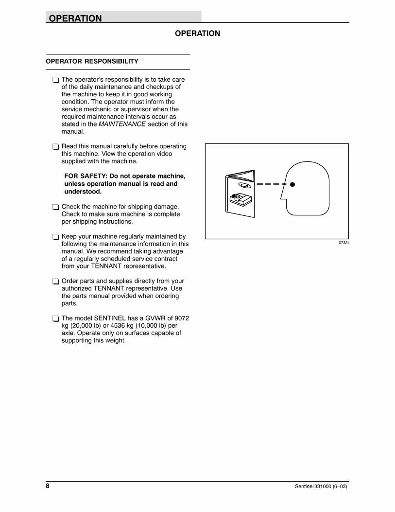
BRAKE PEDAL
The brake pedal stops the machine.
NOTE: The hopper lift and tilt switches will notoperate unless the parking brake is set or theservice brake is applied.
Stop: Take your foot off the propelling pedal andstep on the brake pedal.
ACCESSORY POWER SOCKET
The accessory power socket can be used as acigarette lighter or as an electrical accessorypower outlet.
DIRECTIONAL LEVER
The directional lever controls the forward-reversedirection of travel of the sweeper.
Neutral: Place the lever in the middle, or Neutralposition.
FOR SAFETY: When starting machine,keep foot on brake and directional leverin neutral.
Forward: Push the lever up into the Forwardposition.
NOTE: Machine will not start unless thedirectional lever is in the neutral position. Themachine will not propel with the parking brake on.
Reverse: Pull the lever down into the Reverseposition.
OPERATION
Sentinel 331000 (6−06)22
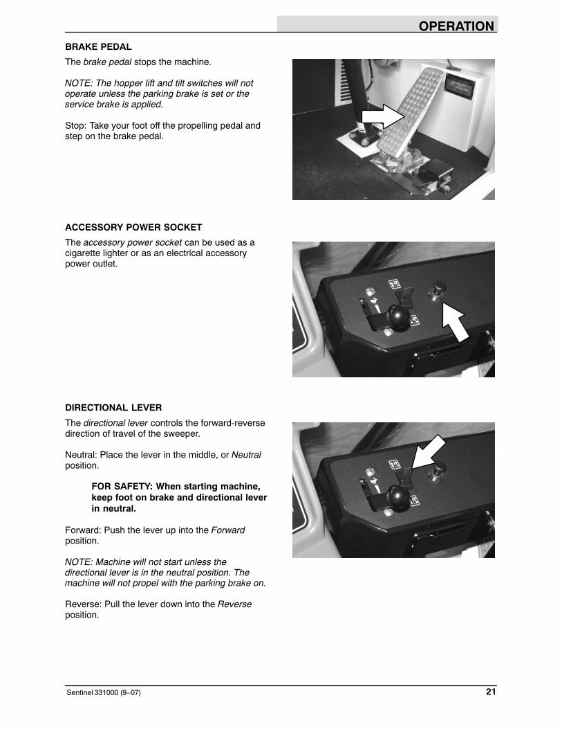
THROTTLE LEVER
The throttle lever controls the engine RPM. Movethe throttle lever till the tachometer shows thedesired engine RPM for transporting or sweeping.See the TACHOMETER section of this manual.
Fast: Push the lever forward.
Idle: Pull the lever backward.
VARIO SWEEPING BRUSH LOCK PIN(OPTION)
The Vario Sweeping Brush lock pin keeps thebrush arm locked in the storage position duringtransport of the machine, or when the brush is notbeing used. Unlock the brush arm before usingthe Vario Sweeping Brush.
Unlock: Pull out the hair cotter pin out of the endof the lock pin.
Lock: Insert the lock pin and secure with the haircotter pin.
WARNING: Brush linkage pinch points.Stay clear when linkage is moving.
VARIO SWEEPING BRUSH TILT/ARM SWITCH(OPTION)
The Vario Sweeping Brush tilt/arm switchtransfers the joystick control between thesweeping brush tilt controls and the sweepingbrush arm movement controls.
Brush Tilt: Press the left side of the switch tocontrol the brush tilt with the joystick.
Brush Arm: Press the right side of the switch tocontrol the brush arm movement with the joystick.

OPERATION
23Sentinel 331000 (6−06)
VARIO SWEEPING BRUSH JOYSTICK(OPTION)
The Vario Sweeping Brush joystick controls theVario Sweeping Brush tilt and the VarioSweeping Brush� arm movement.
When the Vario Sweeping Brush tilt/arm switch isset to the brush tilt position, the Vario SweepingBrush joystick will control the angle of thesweeping brush.
Tilt Brush Front Edge Down: Move and hold thelever forward until the brush has moved into thedesired position.
Tilt Brush Rear Edge Down: Move and hold thelever back until the brush has moved into thedesired position.
Tilt Brush Left: Move and hold the lever to the leftuntil the brush has moved into the desiredposition.
Tilt Brush Right: Move and hold the lever to theright until the brush has moved into the desiredposition.
WARNING: Brush linkage pinch points.Stay clear when linkage is moving.
When the Vario Sweeping Brush tilt/arm switch isset to the sweeping brush arm position, the VarioSweeping Brush joystick will control themovement of the sweeping brush arm.
Swing Sweeping Brush Arm Left: Move and holdthe lever forward until the arm swings into thedesired position.
Swing Sweeping Brush Arm Right: Move andhold the lever back until the arm swings into thedesired position.
Slide Sweeping Brush Arm Left: Move and holdthe lever to the left until the arm slides into thedesired position.
Slide Sweeping Brush Arm Right: Move and holdthe lever to the right until the arm slides into thedesired position.
WARNING: Brush linkage pinch points.Stay clear when linkage is moving.

OPERATION
Sentinel 331000 (6−06)24
VARIO SWEEPING BRUSH ON−OFF SWITCH(OPTION)
The Vario Sweeping Brush on−off switch controlsthe power of the sweeping brush and alsodetermines the direction of brush rotation.
On (right hand sweep): Push the right side of theswitch. The brush will turn on and rotate in acounter−clockwise direction.
On (left hand sweep): Push the left side of theswitch. The brush will turn on and rotate in aclockwise direction.
Off: Place the switch in the middle position. Thebrush turn off.
VARIO SWEEPING BRUSH RAISE−LOWERSWITCH (OPTION)
The Vario Sweeping Brush raise−lower switchcontrols the height of the sweeping brush.
Lower brush: Push the left side of the switch. Thebrush will lower to ground level into thefree−floating position.
Raise brush: Press and hold the right side of theswitch. Release the switch when the brush israised to the desired height.
OPERATION
25Sentinel 331000 (6−03)
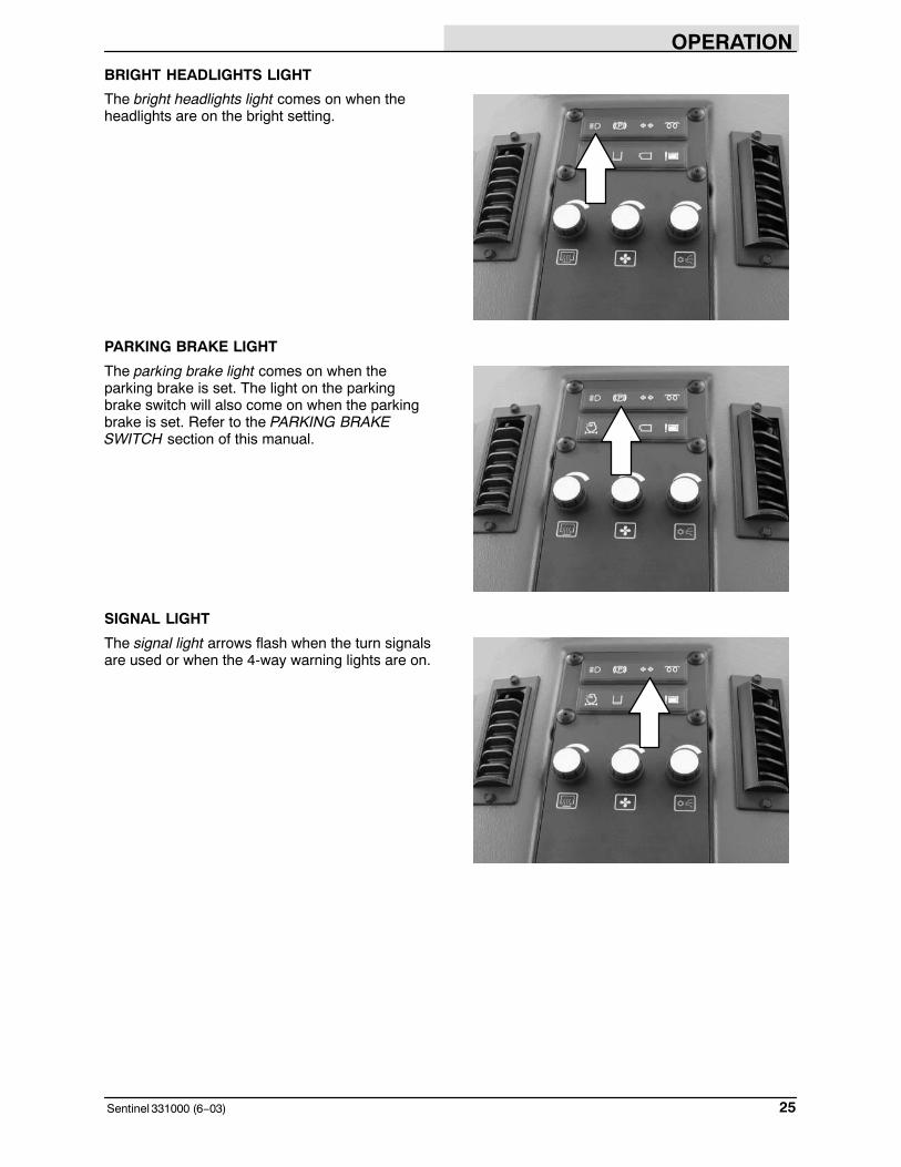
BRIGHT HEADLIGHTS LIGHT
The bright headlights light comes on when theheadlights are on the bright setting.
PARKING BRAKE LIGHT
The parking brake light comes on when theparking brake is set. The light on the parkingbrake switch will also come on when the parkingbrake is set. Refer to the PARKING BRAKESWITCH section of this manual.
SIGNAL LIGHT
The signal light arrows flash when the turn signalsare used or when the 4-way warning lights are on.

OPERATION
Sentinel 331000 (6−03)26
GLOW PLUG LIGHT
The glow plug light comes on when the ignitionswitch is turned counter-clockwise to theaccessories position. The light will go out whenthe engine is ready to start, usually 5 to 30 seconds depending on the weather conditions.
CLOGGED ENGINE AIR FILTER LIGHT
The clogged engine air filter light comes on whenthe engine air filter gets clogged. To clean thefilter, see AIR FILTER in the MAINTENANCEsection of this manual.
WATER TANK LOW LIGHT (OPTION)
The water tank low light comes on when the watertank level is low. The water pump will shut offsoon after this light comes on. If the machine isequipped with a high pressure washer option, it’spump will also shut off if this light comes on.
WARNING: Flammable materials cancause explosion or fire. Do not useflammable materials in tank. Only usewater.

OPERATION
27Sentinel 331000 (6−03)
VACUUM WAND DOOR LIGHT (OPTION)
The vacuum wand door light comes on when thevacuum wand door is closed. Make sure thevacuum wand door is open and the vacuum wanddoor light is off before sweeping with the machine.
HOPPER OVERLOAD LIGHT
The hopper overload light comes on when thehopper reached it’s weight capacity.
For high dump machines, the hopper light willcome on when loaded with more than 1815 kg(4000 lb). When the hopper overload light is on,the hopper can only be tilted to low dump.
For low dump machines, the hopper light willcome on when loaded with more than 3175 kg(7000 lb). The hopper should be dumped whenthe overload light comes on.
HEATER KNOB
The heater knob controls the heater temperature.
Increase: Turn the heater knob clockwise.
Decrease: Turn heater the knobcounter-clockwise.

OPERATION
Sentinel 331000 (6−03)28
FAN KNOB
The fan knob controls the fan speed for the heaterand air conditioner.
Increase: Turn the fan knob clockwise.
Decrease: Turn the fan knob counter-clockwise.
NOTE: This switch does not turn off when theignition is turned off.
AIR CONDITIONER KNOB (OPTION)
The air conditioner knob controls the airconditioner temperature.
Increase The Cool Temperature: Turn the airconditioner knob clockwise.
Decrease The Cool Temperature: Turn airconditioner the knob counter-clockwise.
NOTE: The air conditioner will NOT work unlessthe fan is turned on.
AIR CIRCULATION VENTS
There are numerous air circulation vents in theoperator cab. There is a set for both thepassenger and the driver. If desired, the vents canbe closed on the passenger side of the cab formore air flow to the drivers side of the cab. Thevents in front of the dash panel are for defrosting.

OPERATION
29Sentinel 331000 (6−03)
LOW BRAKE PRESSURE LIGHT
The low brake pressure light indicates low brakepressure. If this light comes on when the machineis started, do not move the machine until the lightgoes out. If the light comes on during operation ofthe machine, proceed with caution out ofintersections or traffic and park the machine. Ifbrake pressure drops too low, the parking brakewill come on automatically and will not releaseuntil brake pressure is restored. Contact yourservice personnel to restore the brake pressure.
INCLINE LIGHT (High Dump Model)
The incline light will come on when the machine ison an incline that is unsafe for high dumping thehopper. It will come on when the front to backincline is more than 11� and the side to sideincline is more than 4�. The machine will not highdump when this light is on.
FOR SAFETY: Only dump the hopper ona level surface.

OPERATION
Sentinel 331000 (6−06)30
ENGINE SHUTDOWN OVERRIDE SWITCH
The engine shutdown override switch will bypassthe high water temperature and low oil pressureshutdown feature. Press and hold the switch bothto start and operate the machine. This switch isfor use if the machine’s automatic shutdownfeature happens in an intersection or in traffic. DoNOT use this switch for more than a few secondsor damage to the engine could occur. SeeENGINE WATER TEMPERATURE GAUGE andENGINE OIL PRESSURE GAUGE sections ofthis manual.
PARKING BRAKE SWITCH
The parking brake switch sets and releases thefront axle as well as disables the propellingsystem. When the ignition switch is turned off, theparking brake will come on automatically.
NOTE: The hopper lift and tilt switches will notoperate unless the parking brake is set or theservice brake is applied.
NOTE: The high pressure washer option will notoperate unless the parking brake is set.
Set: Press the top part of the parking brakeswitch. The indicator light in the switch as well asthe parking brake light will come on.
FOR SAFETY: Before leaving orservicing machine, stop on levelsurface, set parking brake, turn offmachine and remove key.
Release: Press the bottom part of the parkingbrake switch. The indicator light in the switch aswell as the parking brake light will turn off.
NOTE: If brake pressure drops too low, theparking brake will come on automatically and willnot release until brake pressure is restored. Whenthis happens, this switch will NOT indicate that itis set. See LOW BRAKE PRESSURE LIGHTsection of this manual.

OPERATION
31Sentinel 331000 (6−03)
LEFT SIDE BRUSH WATER VALVE KNOB(OPTION)
The left side brush water valve knob controls theamount of water spray to the left side brush.
Increase Water Spray: Turn the left side brushwater valve knob counter-clockwise.
Decrease Water Spray: Turn the left side brushwater valve knob clockwise.
Stop Water Spray: Turn the water valve knobclockwise until it comes to a complete stop toclose the water supply. If this is NOT done whenthe machine is shut off, water will continue to flow.
NOTE: The water pump switch needs to be onfor the water valves to operate.
VARIO SWEEPING BRUSH LEFT WATERVALVE KNOB (OPTION)
The Vario Sweeping Brush left water valve knobcontrols the amount of water spray to thesweeping brush when it is on left side of themachine.
Increase Water Spray: Turn the water valve knobcounter-clockwise.
Decrease Water Spray: Turn the water valveknob clockwise.
Stop Water Spray: Turn the water valve knobclockwise until it comes to a complete stop toclose the water supply. If this is NOT done whenthe machine is shut off, water will continue to flow.
NOTE: The water pump switch needs to be onfor the water valves to operate.

OPERATION
Sentinel 331000 (6−06)32
VARIO SWEEPING BRUSH RIGHT WATERVALVE KNOB (OPTION)
The Vario Sweeping Brush right water valve knobcontrols the amount of water spray to thesweeping brush when the it is on the right side ofthe machine.
Increase Water Spray: Turn the water valve knobcounter-clockwise.
Decrease Water Spray: Turn the water valveknob clockwise.
Stop Water Spray: Turn the water valve knobclockwise until it comes to a complete stop toclose the water supply. If this is NOT done whenthe machine is shut off, water will continue to flow.
NOTE: The water pump switch needs to be onfor the water valves to operate.
RIGHT SIDE BRUSH WATER VALVE KNOB(OPTION)
The right side brush water valve knob controls theamount of water spray to the right side brush.
Increase Water Spray: Turn the right side brushwater valve knob counter-clockwise.
Decrease Water Spray: Turn the right side brushwater valve knob clockwise.
Stop Water Spray: Turn the water valve knobclockwise until it comes to a complete stop toclose the water supply. If this is NOT done whenthe machine is shut off, water will continue to flow.
NOTE: The water pump switch needs to be onfor the water valves to operate.

OPERATION
33Sentinel 331000 (12−03)
FUSES
Fuses are a one-time protection device designedto stop the flow of current in the event of a circuitoverload. This machine uses automotive ATOtype fuses. Never substitute higher value fusesthan specified.
The fuses are located in the fuse box under thefuse cover on the center console.
Fuse Rating Circuit Protected
FU-1 30 A Accessory
FU-2 30 A Accessory
FU−3 25 A Turn Signals
FU-4 15 A Night Lights
FU-5 20 A Rotating / Sidebrush
FU-6 20 A Headlight
FU-7 15 A Taillight / Marker
FU-8 10 A Water Pump
FU-9 15 A Accessory Power Socket
FU-10 10 A Horn
FU-11 10 A Domelight / Radio
FU-12 5 A Auto Lube (option)
FU-13 Traffic Advisor
FU-14 Open
FU-15 30 A Heater / Air Conditioner
FU-16 15 A Logic Power
FU-17 15 A Hopper Control
FU-18 10 A Logic
FU-19 10 A Sensors
FU-20 Key Cntrld Optn (Open)
FU-21 Key Cntrld Optn (Open)
FU-22 Traffic Advisor
FU-23 10 A Auto Lube (option)
FU-24 10 A Vario Front Brush
FU-25 10 A Radio
FU-26 10 A Wipers
FU-27 15 A Neutral Start Propel
FU-28 15 A Daytime Running Lights
FU-29 80 A Preheat

OPERATION
Sentinel 331000 (6−03)34
ENGINE WATER TEMPERATURE GAUGE
The engine water temperature gauge shows theengine coolant temperature. If the engine coolanttemperature is too hot, the LED indicator light willblink. If this happens, stop the engine, locate theproblem and have it corrected. If the engine is notturned off, the machine is equipped with anautomatic shutdown feature that will turn off theengine. This keeps the engine from beingdamaged. To override this automatic shutdown,refer to the ENGINE SHUTDOWN OVERRIDESWITCH section of this manual.
FUEL LEVEL GAUGE
The fuel level gauge indicates how much fuel is inthe fuel tank. The LED indicator light will blinkwhen the fuel level is low.
NOTE: Do not let the fuel tank empty completely.Air can enter the fuel system and requirebleeding, before the next engine start.
ENGINE OIL PRESSURE GAUGE
The engine oil pressure gauge displays the engineoil pressure. If the oil pressure falls too low, theLED light will blink. If this happens, stop theengine, locate the problem and have it corrected.If the engine is not turned off, the machine isequipped with an automatic shutdown feature thatwill turn off the engine. This keeps the enginefrom being damaged. To override this automaticshutdown, refer to the ENGINE SHUTDOWNOVERRIDE SWITCH section of this manual.
RPML
H
F
E L
H
L
H
MPHkm/h
1800
000239
5
150
351927
RPML
H
F
E L
H
L
H
MPHkm/h
1800
000239
5
150
351927
RPML
H
F
E L
H
L
H
MPHkm/h
1800
000239
5
150
351927

OPERATION
35Sentinel 331000 (6−03)
VOLTMETER
The voltmeter displays the existing voltage of thebattery. When the voltage is not within the normalrange − 12 to 14 Volts, the LED light will blink. Ifthis happens, stop operating the machine, locatethe problem and have it corrected.
HOURMETER
The hourmeter records the number of hours themachine has been operated. Use this informationto determine machine maintenance intervals.
ODOMETER
The odometer records the distance that themachine has been driven. Use this information todetermine machine maintenance intervals such astire wear.
SPEEDOMETER
The speedometer displays the machines travelspeed. Use this for determining the properoperating speed for sweeping and transporting.
RPML
H
F
E L
H
L
H
MPHkm/h
1800
000239
5
150
351927
RPML
H
F
E L
H
L
H
MPHkm/h
1800
000239
5
150
351927
RPML
H
F
E L
H
L
H
MPHkm/h
1800
000239
5
150
351927
RPML
H
F
E L
H
L
H
MPHkm/h
1800
000239
5
150
351927

OPERATION
Sentinel 331000 (6−03)36
TACHOMETER
The tachometer consists of a numeric display, anLED visual display, and a green SWEEP light.The numeric display shows the engine RPM.Move the throttle lever till the tachometer showsthe desired engine RPM for transporting orsweeping. See the THROTTLE LEVER section ofthis manual.
The tachometer’s LED visual display indicateswhen the engine RPM is set for proper sweeping.When the amber LED light is in the middle of thegauge (between the blue markings), the enginethrottle is at a proper setting for sweeping. Thedesired sweeping speed is between 1600 and2000 RPM. Refer to the chart in the SWEEPINGsection.
The tachometer’s green SWEEP light willilluminate when the engine RPM is set for propersweeping. If the engine speed is operating below1600 RPM, the green SWEEP light will turn offwhile the sweeping functions will continue tooperate. If the engine speed is operating too fastfor sweeping (above 2000 RPM), the greenSWEEP light will blink and an audio alarm willsound. This will continue for 15 seconds, then thesweeping functions will stop and raise.
RPML
H
F
E L
H
L
H
MPHkm/h
1800
000239
5
150
351927
RPML
H
F
E L
H
L
H
MPHkm/h
1800
000239
5
150
351927
RPML
H
F
E L
H
L
H
MPHkm/h
1800
000239
5
150
351927
OPERATION
37Sentinel 331000 (6−03)
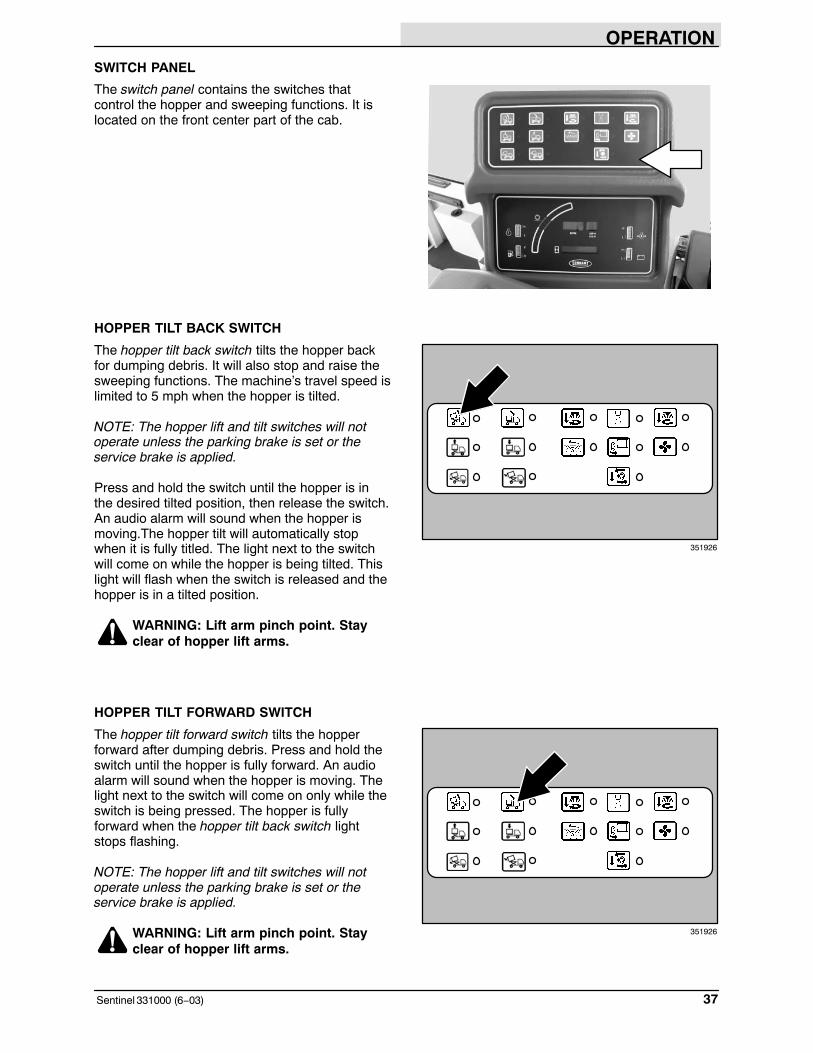
SWITCH PANEL
The switch panel contains the switches thatcontrol the hopper and sweeping functions. It islocated on the front center part of the cab.
HOPPER TILT BACK SWITCH
The hopper tilt back switch tilts the hopper backfor dumping debris. It will also stop and raise thesweeping functions. The machine’s travel speed islimited to 5 mph when the hopper is tilted.
NOTE: The hopper lift and tilt switches will notoperate unless the parking brake is set or theservice brake is applied.
Press and hold the switch until the hopper is inthe desired tilted position, then release the switch.An audio alarm will sound when the hopper ismoving.The hopper tilt will automatically stopwhen it is fully titled. The light next to the switchwill come on while the hopper is being tilted. Thislight will flash when the switch is released and thehopper is in a tilted position.
WARNING: Lift arm pinch point. Stayclear of hopper lift arms.
HOPPER TILT FORWARD SWITCH
The hopper tilt forward switch tilts the hopperforward after dumping debris. Press and hold theswitch until the hopper is fully forward. An audioalarm will sound when the hopper is moving. Thelight next to the switch will come on only while theswitch is being pressed. The hopper is fullyforward when the hopper tilt back switch lightstops flashing.
NOTE: The hopper lift and tilt switches will notoperate unless the parking brake is set or theservice brake is applied.
WARNING: Lift arm pinch point. Stayclear of hopper lift arms.
351926
351926

OPERATION
Sentinel 331000 (6−03)38
HOPPER LIFT SWITCH (High Dump Model)
The hopper lift switch will raise the hopper for highdumping. It will also stop and raise the sweepingfunctions. The machine’s travel speed is limited to3 mph when the hopper is in the raised position.
NOTE: The hopper lift and tilt switches will notoperate unless the parking brake is set or theservice brake is applied.
NOTE: The minimum clearance height needed tohigh dump the hopper is 5060 mm (16.6 in).
WARNING: High dump verticalclearance. Stay clear of overheadobstructions and power lines.
Press and hold the switch until the hopper is atthe desired raised position, then release theswitch. An audio alarm will sound when thehopper is moving. The hopper lift willautomatically stop when it is it is fully raised. Thelight next to the switch will come on while thehopper is being raised. This light will flash whenthe switch is released with the hopper in a raisedposition.
NOTE: The hopper will not lift if the optionalhopper incline or overload light is on. Thisindicates that the machine is either on an inclinethat is unsafe or that the hopper is too heavy forhigh dumping the hopper.
HOPPER LOWER SWITCH (High Dump Model)
The hopper lower switch lowers the hopper afterhigh dumping. Press and hold the switch until thehopper is fully lowered. An audio alarm will soundwhen the hopper is moving. The light next to theswitch will come on only while the switch is beingpressed. The hopper is fully lowered when thehopper lift switch light stops flashing.
NOTE: The hopper lift and tilt switches will notoperate unless the parking brake is set or theservice brake is applied.
WARNING: Lift arm pinch point. Stayclear of hopper lift arms.
351926
351926
OPERATION
39Sentinel 331000 (6−03)
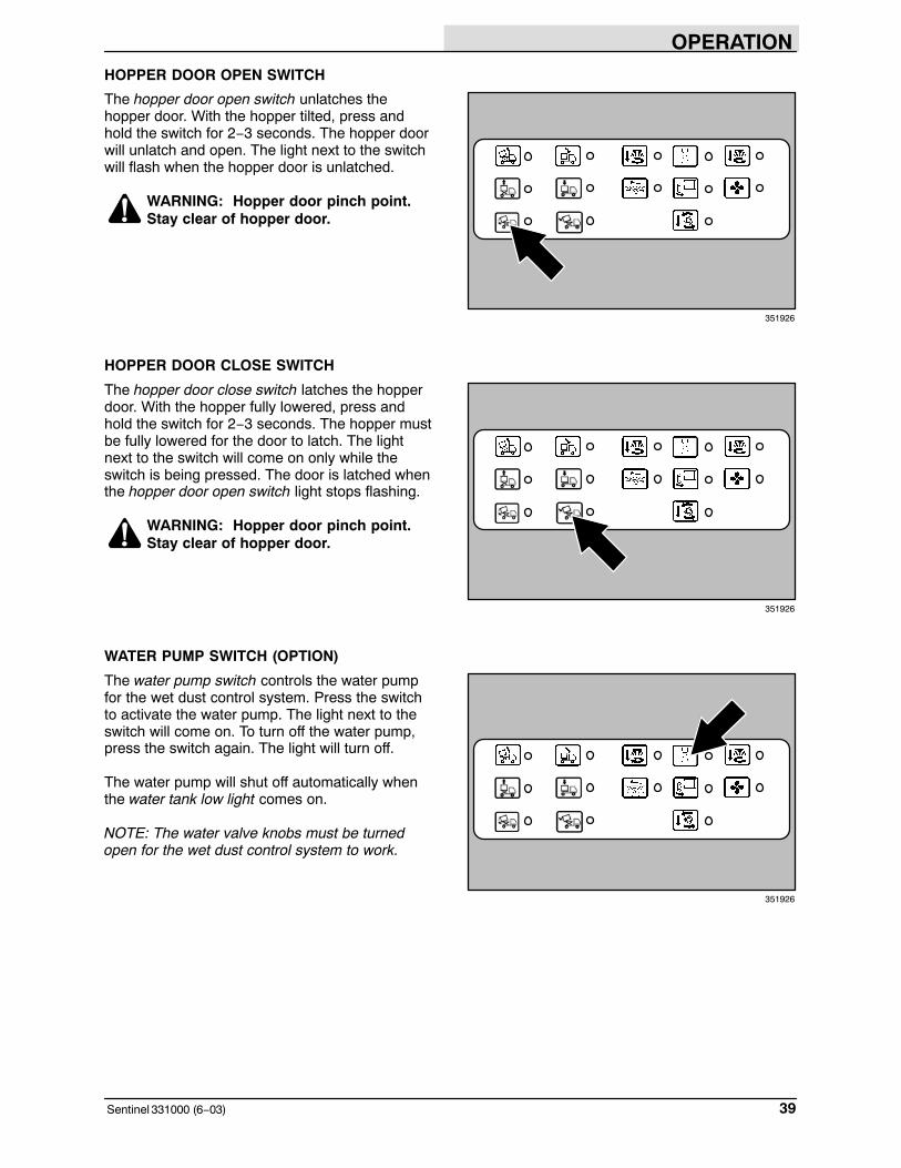
HOPPER DOOR OPEN SWITCH
The hopper door open switch unlatches thehopper door. With the hopper tilted, press andhold the switch for 2−3 seconds. The hopper doorwill unlatch and open. The light next to the switchwill flash when the hopper door is unlatched.
WARNING: Hopper door pinch point.Stay clear of hopper door.
HOPPER DOOR CLOSE SWITCH
The hopper door close switch latches the hopperdoor. With the hopper fully lowered, press andhold the switch for 2−3 seconds. The hopper mustbe fully lowered for the door to latch. The lightnext to the switch will come on only while theswitch is being pressed. The door is latched whenthe hopper door open switch light stops flashing.
WARNING: Hopper door pinch point.Stay clear of hopper door.
WATER PUMP SWITCH (OPTION)
The water pump switch controls the water pumpfor the wet dust control system. Press the switchto activate the water pump. The light next to theswitch will come on. To turn off the water pump,press the switch again. The light will turn off.
The water pump will shut off automatically whenthe water tank low light comes on.
NOTE: The water valve knobs must be turnedopen for the wet dust control system to work.
351926
351926
351926

OPERATION
Sentinel 331000 (6−03)40
LEFT SIDE BRUSH SWITCH (OPTION)
The left side brush switch controls the left sidebrush. Press the switch to lower and turn on theleft side brush. The light next to the switch willcome on. To lift and turn off the left side brush,press the switch again. The light will turn off.
NOTE: The side brushes will automatically turn onwith the SWEEP SWITCH IF they were in the “on”position when the sweep switch was last turnedoff.
WARNING: Side brush can move. Donot step on side brush.
RIGHT SIDE BRUSH SWITCH
The right side brush switch controls the right sidebrush. Press the switch to lower and turn on theright side brush. The light next to the switch willcome on. To lift and turn off the right side brush,press the switch again. The light will turn off.
NOTE: The side brushes will automatically turn onwith the SWEEP SWITCH IF they were in the “on”position when the sweep switch was last turnedoff.
WARNING: Side brush can move. Donot step on side brush.
FILTER SHAKER SWITCH
The filter shaker switch controls the hopper dustfilter shaker system. It is used to shake clean thedust from the filter. With the throttle in the idleposition, press and hold the switch for 1 to 2seconds to activate the system. The light next tothe switch will come on while the filter is shaking.The filter will shake for about 30 seconds, then itwill stop and the light will turn off.
351926
351926
351926
OPERATION
41Sentinel 331000 (6−03)
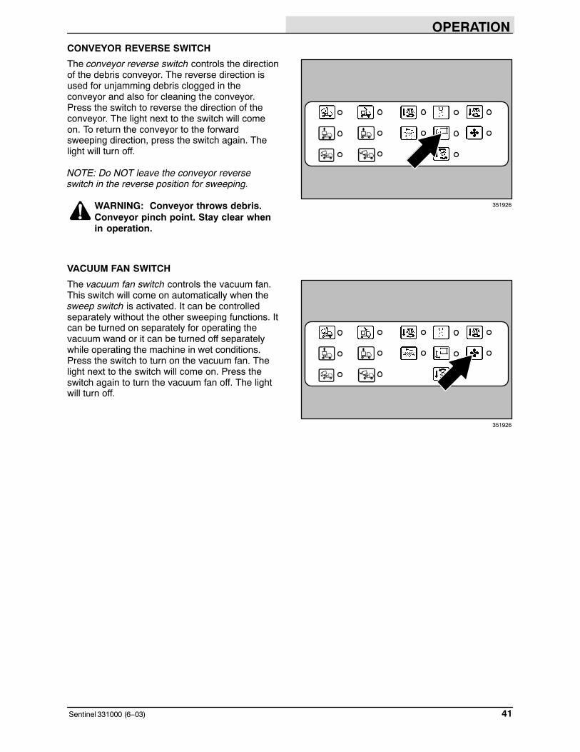
CONVEYOR REVERSE SWITCH
The conveyor reverse switch controls the directionof the debris conveyor. The reverse direction isused for unjamming debris clogged in theconveyor and also for cleaning the conveyor.Press the switch to reverse the direction of theconveyor. The light next to the switch will comeon. To return the conveyor to the forwardsweeping direction, press the switch again. Thelight will turn off.
NOTE: Do NOT leave the conveyor reverseswitch in the reverse position for sweeping.
WARNING: Conveyor throws debris.Conveyor pinch point. Stay clear whenin operation.
VACUUM FAN SWITCH
The vacuum fan switch controls the vacuum fan.This switch will come on automatically when thesweep switch is activated. It can be controlledseparately without the other sweeping functions. Itcan be turned on separately for operating thevacuum wand or it can be turned off separatelywhile operating the machine in wet conditions.Press the switch to turn on the vacuum fan. Thelight next to the switch will come on. Press theswitch again to turn the vacuum fan off. The lightwill turn off.
351926
351926

OPERATION
Sentinel 331000 (6−03)42
SWEEP SWITCH
The sweep switch controls the sweepingfunctions of the machine. These functions includethe vacuum fan, the main brush, the conveyor,and side brushes. They do NOT control the Variobrush.
NOTE: The sweep switch can NOT be activated ifany of the hopper control switches are lit. Thehopper must be in the fully forward and loweredposition with the hopper door latched beforesweeping.
To start the sweeping functions, press the sweepswitch. The vacuum fan will come on, the mainbrush and conveyor will lower and will also comeon. The lights next to these switches will come on.The side brushes will also automatically turn onwith the sweep switch IF they were in the onposition when the sweep switch was last turnedoff.
NOTE: If the engine speed is operating too fastfor sweeping, the sweeping functions will lift andturn off after 15 seconds. See the TACHOMETERsection of this manual.
To stop and raise the sweeping functions, pressthe sweep switch again. The lights next to thesesweeping function switches will turn off.
351926

OPERATION
43Sentinel 331000 (6−03)
4-WAY WARNING LIGHTS SWITCH
The 4-way warning lights switch powers on andoff the warning lights.
On: Press the top of the 4-way warning lightsswitch. The light will come on.
Off: Press the bottom of the 4-way warning lightsswitch. The light will go off.
HAZARD LIGHT SWITCH
The hazard light switch powers on and off thehazard light.
On: Press the top of the hazard light switch. Thelight will come on.
Off: Press the bottom of the hazard light switch.The light will go off.
SIDE BRUSH SPOT LIGHT(S) SWITCH
The side brush spot light(s) switch powers on andoff the side brush spot light(s).
On: Press the top of the side brush spot light(s)switch. The light(s) will come on.
Off: Press the bottom of the side brush spotlight(s) switch. The light(s) will go off.

OPERATION
Sentinel 331000 (6−03)44
REAR NIGHT SWEEPING LIGHT SWITCH(OPTION)
The rear night sweeping light switch powers onand off the rear sweeping light.
On: Press the top of the rear night sweeping lightswitch. The light will come on.
Off: Press the bottom of the rear night sweepinglight switch. The light will go off.
FRONT NIGHT SWEEPING LIGHT SWITCH(OPTION)
The front night sweeping light switch powers onand off the front sweeping light.
On: Press the top of the front night sweepinglight switch. The light will come on.
Off: Press the bottom of the front night sweepinglight switch. The light will go off.
HIGH PRESSURE WASHER SWITCH (OPTION)
The high pressure washer switch powers on andoff the high pressure washer.
On: Press the top of the high pressure washerswitch. The light will come on.
NOTE: The high pressure washer option will notoperate unless the parking brake is set.
Off: Press the bottom of the high pressurewasher switch. The light will go off.
FOR SAFETY: When using pressurizedair or water, wear eye and earprotection.

OPERATION
45Sentinel 331000 (9−07)
DOME AND MAP LIGHT SWITCH
The dome and map light switch controls the domeand map light on the ceiling of the cab.
Map Light On: Push the switch toward thepassenger side of the cab.
Dome and Map Light On: Pull the switch towardthe operator side of the cab.
Off: Place the switch to the middle position.
RADIO AND COMPACT DISK PLAYER(OPTION)
The radio and compact disk player is locatedabove the operator. Refer to the radio/compactdisk player’s manual for operation.
LATCHES
The cab doors, side doors, and main brushaccess doors are secured with latches.
Open the Cab Doors: Pull out on the latch handleand turn the latch handle 90°.
Open the Side Doors: Push in the button and pullon the latch handle.
Open the Main Brush Access Doors: Pull on therubber latch until the door is loose. Remove thedoor by pulling the door from the pins in themachine frame.

OPERATION
Sentinel 331000 (6−03)46
TRAFFIC ADVISOR SIGNAL LIGHT SWITCH(OPTION)
The traffic advisor signal light switch controls thetraffic advisor signal light on the back of themachine.
Lights On (High): Press the top of the switch.
Lights On (Low): Press the bottom of the switch.
Off: Press the switch to the middle position.
TRAFFIC ADVISOR SIGNAL LIGHT FUNCTIONKNOB (OPTION)
The traffic advisor signal light function knob allowsthe machine operator to choose between the fourdifferent signal light patterns.
Use the traffic advisor signal light function knob toselect between the LEFT, RIGHT, SPLIT andFLASH patterns.
The light strip in the lower right hand corner of thecontroller mirrors the light pattern that is beingdisplayed on the traffic advisor signal light on theback of the machine.

OPERATION
47Sentinel 331000 (6−03)
HOPPER SUPPORT PIN
The hopper support pin holds the hopper in the tiltback position to allow work under the hopper. DONOT rely on the machine hydraulic system tokeep the hopper raised. See ENGAGINGHOPPER SUPPORT PIN section of this manual.
WARNING: Raised hopper may fall.Engage hopper support pin.
The hopper support pin is stored on the right rearfender under the hopper.
OPERATION
Sentinel 331000 (6−03)48
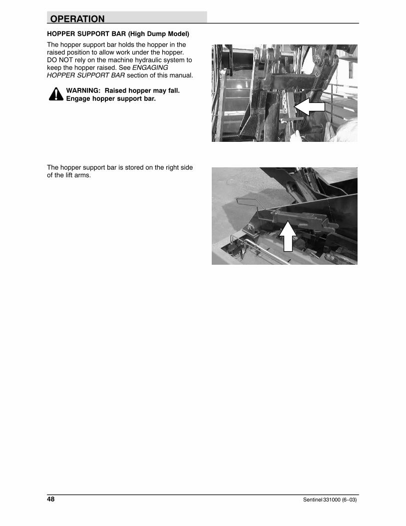
HOPPER SUPPORT BAR (High Dump Model)
The hopper support bar holds the hopper in theraised position to allow work under the hopper.DO NOT rely on the machine hydraulic system tokeep the hopper raised. See ENGAGINGHOPPER SUPPORT BAR section of this manual.
WARNING: Raised hopper may fall.Engage hopper support bar.
The hopper support bar is stored on the right sideof the lift arms.

OPERATION
49Sentinel 331000 (6−03)
D
AB
C
E
F
G
H
I
J K
HOW THE MACHINE WORKS
The steering wheel (A) controls the direction ofmachine travel. The directional lever (B) controlsthe forward/reverse direction. The propelling pedal(C) controls machine speed. The brake pedal (D)slows and stops the machine.
The side brush (E) and vario brush (option) (F)sweep debris into the path of the main brush (G).The main brush (G) sweeps debris from thesurface onto the conveyer (H), which transfers thedebris into the hopper (I). The vacuum system (J)pulls dust and air through the hopper (I) and thehopper dust filter (K).
The machine has a right side brush (E), anoptional Vario Sweeping Brush� (F), and anoptional left side brush. There is also either a wetor dry dust control system.
When sweeping is finished, clean the hopper dustfilter (K) and empty the hopper (I).

OPERATION
Sentinel 331000 (6−03)50
PRE-OPERATION CHECKLIST
� Check the engine oil level.
� Check the engine coolant level.
� Check the windshield washer fluid level.
� Check the radiator and hydraulic cooler finsfor debris.
� Check the hydraulic fluid level.
� Check the air filter indicator.
� Check the skirts and seals for damage andwear.
� Check the condition of the sweepingbrushes. Remove any string, banding,plastic wrap, or other debris wrapped around them.
� Check the sweeping brush patterns foradjustment.
� Check the condition of the hopper dust filterand seals. Clean as required.
� Check the brakes and steering for properoperation.
� Check the fuel level.
� Empty the debris hopper.
� Check the service records to determinemaintenance requirements.

OPERATION
51Sentinel 331000 (9−07)
STARTING THE MACHINE
1. Check the directional lever to make sure it isin the middle neutral position.
NOTE: Machine will not start unless thedirectional lever is in the neutral position.
2. Sit in the operator’s seat and fasten the seatbelt. Place your foot on the brake pedal orset the parking brake.
NOTE: The machine will not propel unless theoperator is in the seat.
3. Move the throttle lever back to the idleposition.

OPERATION
Sentinel 331000 (9−08)52
4. Turn the key counter-clockwise. The glowplugs light will come on. When the glow pluglight goes out, usually for 5 to 30 secondsdepending on the weather conditions, theengine is ready to start.
NOTE: The preheat is not necessary if thetemperature is above 10� C (50� F).
5. Turn the ignition switch key clockwise untilthe engine starts.
NOTE: Do not operate the starter motor for morethan 10 seconds at a time or after the engine hasstarted. Allow the starter to cool between startingattempt or damage to the starter motor mayoccur.
6. Turbo Charged Engines: Allow the engine tooperate for at least 30 seconds at low idlebefore adjusting the throttle lever.
7. Allow the engine and hydraulic system towarm up three to five minutes.
WARNING: Engine emits toxic gases.Severe respiratory damage orasphyxiation can result. Provideadequate ventilation. Consult with yourregulatory agency for exposure limits.Keep engine properly tuned.
8. Adjust the throttle lever to the desiredengine speed.

OPERATION
53Sentinel 331000 (9−07)
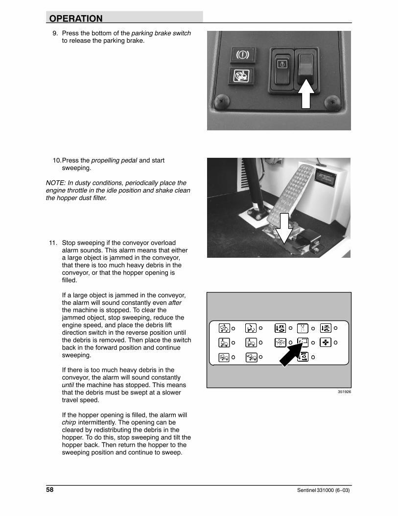
9. Press the bottom of the parking brake switchto release the parking brake.
10.Place the directional lever in the Forwardposition.
11.Release the brake pedal and press on thepropelling pedal to transport the machine.The more foot pressure, the faster themachine will travel.
NOTE: The machine will not propel unless theoperator is in the seat and the parking brake isreleased.
12. Drive the machine to the area to be swept.When transporting to the sweeping area andequipped with the Vario Sweeping Brush�,lock the brush into the travel support withthe guide pin.
FOR SAFETY: When using machine,always follow safety and traffic rules.

OPERATION
Sentinel 331000 (6−03)54
SWEEPING AND BRUSH INFORMATION
The model Sentinel has a GVWR of 9072 kg (20,000 lb) or 4536 kg (10,000 lb) per axle.Operate only on surfaces capable of supportingthis weight.
Avoid bulky debris such as crates, boxes, treebranches, and very heavy material. Avoid piecesof straps, twine, rope, etc., which could becomeentangled in brush, brush plugs or the conveyor.
Plan the sweeping in advance. Try to arrange longruns with minimum stopping and starting. Sweepas straight a path as possible. Overlap the brushpaths.
Avoid turning the steering wheel too sharply whenthe machine is in motion. The machine is veryresponsive to the movement of the steeringwheel. Avoid sudden turns, except inemergencies.
Use the wet dust control option in dustyconditions. With wet roads, do not use the wetdust control option.
For best results, use the correct brush type foryour sweeping application. The main sweepingbrush is a polypropylene brush. The following arerecommendations for side brush and VarioSweeping Brush�.
Polypropylene and Wire Side Brush −Recommended for general purpose sweeping.Best combination of sweeping andaggressiveness.
Flat Wire Side Brush − Recommended foroutside and curb-side sweeping where soilage isheavy or compacted. The stiff wire bristles dig outsoilage. This brush does not sweep as good asthe Polypropylene and Wire Side Brush but isrecommended for foundry sweeping where heatmay melt synthetic bristles.
Polypropylene Side Brush − Recommended forsweeping where you cannot have wire fragments.This brush does not sweep as good as thePolypropylene and Wire Side Brush but isrecommended for areas such as airports.
OPERATION
55Sentinel 331000 (6−03)
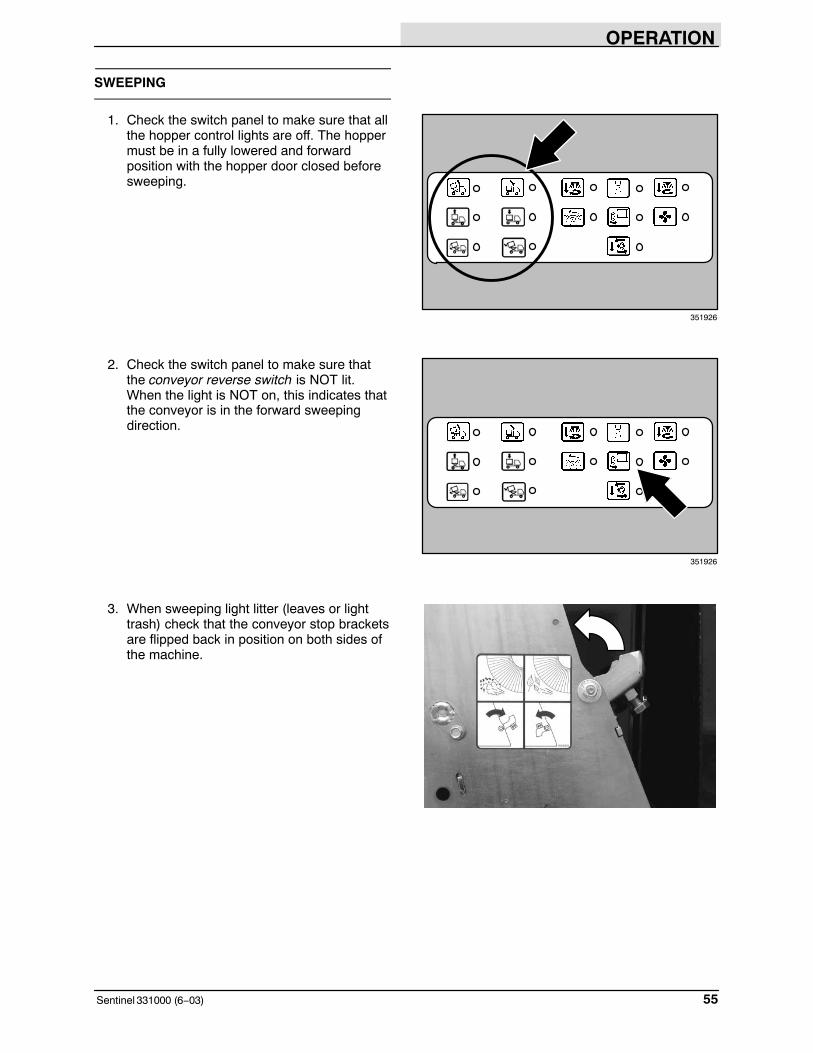
SWEEPING
1. Check the switch panel to make sure that allthe hopper control lights are off. The hoppermust be in a fully lowered and forwardposition with the hopper door closed beforesweeping.
2. Check the switch panel to make sure thatthe conveyor reverse switch is NOT lit.When the light is NOT on, this indicates thatthe conveyor is in the forward sweepingdirection.
3. When sweeping light litter (leaves or lighttrash) check that the conveyor stop bracketsare flipped back in position on both sides ofthe machine.
351926
351926

OPERATION
Sentinel 331000 (9−07)56
4. Adjust and start the Vario Sweeping Brush ifequipped. Refer to the Vario SweepingBrush section of this manual.
5. Move the throttle lever till the tachometershows the desired engine RPM for the typeof sweeping you are doing. Refer to thefollowing chart.
DebrisEngine
RPMTravelSpeed
General Debris 1600−1800RPM
(5−13 kmh)3−5 mph
Fine Dust 1500−1800RPM
(5−13 kmh)3−5 mph
Light Debris (Leaves, grass)
(Shake filter often)
1800−2000RPM
(5−13 kmh)3−5 mph
Wet Sweeping(Vacuum fan on)
1800−2000RPM
(5−13 kmh)3−5 mph
Heavy Debris 1800−2000RPM
Slower than5 kph
(3 mph)
Vacuum Wand(Ear plugs manda-
tory)
2300−2400RPM
None
NOTE: Do NOT sweep with engine speed higherthan 2000 RPM. If the engine speed is operatingabove 2000 RPM, the green SWEEP light willblink and an audio alarm will sound. This willcontinue for 15 seconds, then the main sweepingfunctions will lift and turn off.
351927
RPML
H
F
E L
H
L
H
MPHkm/h
1800
000239
5
150

OPERATION
57Sentinel 331000 (6−03)
6. Press the sweep switch. This will lower andstart the sweeping functions. The lights nextto these switches will come on.
NOTE: The side brushes will automatically turn onwith the SWEEP SWITCH IF they were in the onposition when the sweep switch was last turnedoff.
7. Start the wet dust control system ifequipped. Refer to the wet dust controlsystem section of this manual.
8. Press the side brush switch(es). This willlower and start the side brush(es). Thelight(s) next to the switch(es) will come on.
NOTE: The side brushes will automatically turn onwith the SWEEP SWITCH IF they were in the onposition when the sweep switch was last turnedoff.
351926
351926
351926
OPERATION
Sentinel 331000 (6−03)58
9. Press the bottom of the parking brake switchto release the parking brake.
10.Press the propelling pedal and startsweeping.
NOTE: In dusty conditions, periodically place theengine throttle in the idle position and shake cleanthe hopper dust filter.
11. Stop sweeping if the conveyor overloadalarm sounds. This alarm means that eithera large object is jammed in the conveyor,that there is too much heavy debris in theconveyor, or that the hopper opening isfilled.
If a large object is jammed in the conveyor,the alarm will sound constantly even afterthe machine is stopped. To clear thejammed object, stop sweeping, reduce theengine speed, and place the debris liftdirection switch in the reverse position untilthe debris is removed. Then place the switchback in the forward position and continuesweeping.
If there is too much heavy debris in theconveyor, the alarm will sound constantlyuntil the machine has stopped. This meansthat the debris must be swept at a slowertravel speed.
If the hopper opening is filled, the alarm willchirp intermittently. The opening can becleared by redistributing the debris in thehopper. To do this, stop sweeping and tilt thehopper back. Then return the hopper to thesweeping position and continue to sweep.
351926

OPERATION
59Sentinel 331000 (6−03)
STOP SWEEPING
1. Press the sweep switch. This will raise andstop the sweeping functions. The lights nextto these sweeping function switches will turnoff.
2. Stop the wet dust control system ifequipped. Refer to the wet dust controlsystem section of this manual.
3. Check to make sure all the sweepingfunction lights are out. If any lights are lit,press the switch to turn it off.
351926
351926
351926

OPERATION
Sentinel 331000 (6−06)60
4. Stop the Vario Sweeping Brush if equipped.Refer to the Vario Sweeping Brush sectionof this manual.
5. Place the engine throttle in the idle positionand press the filter shaker switch to cleanthe hopper filter. The filter will shake forabout 30 seconds. The light next to theswitch will come on while the filter isshaking, then turn off.
NOTE: Shake the dust filter before tilting thehopper.
351926

OPERATION
61Sentinel 331000 (6−03)
EMPTYING THE HOPPER
1. Drive the machine slowly to the debriscollection site or debris container. Make surethe machine is on level ground beforedumping the hopper.
FOR SAFETY: Only dump the hopper ona level surface.
2. Press and hold the brake pedal with yourfoot, then push the throttle lever forward toincrease the engine speed.
NOTE: The hopper will not lift or tilt unless theparking brake is set or the service brake isapplied.
3. For High Dump Model: Press and hold thehopper lift switch until the hopper is at thedesired raised position, then release theswitch. An audio alarm will sound when thehopper is moving.
NOTE: The hopper will not lift if the optionalhopper incline or overload light is on. Thisindicates that the machine is either on an inclinethat is unsafe or that the hopper is too heavy forhigh dumping the hopper.
NOTE: The minimum clearance height needed tohigh dump the hopper is 5060 mm (16.6 in).
WARNING: High dump verticalclearance. Stay clear of overheadobstructions and power lines.
351926

OPERATION
Sentinel 331000 (9−07)62
4. Place the directional lever in the reverseposition, release the brake and slowly backthe machine up to the debris site orcontainer.
FOR SAFETY: Move machine with carewhen hopper is raised.
5. Press and hold the brake pedal with yourfoot.
NOTE: The hopper will not lift or tilt unless theparking brake is set or the service brake isapplied.
6. Press and hold the hopper tilt back switchuntil the hopper is in the desired tiltedposition, then release the switch. An audioalarm will sound when the hopper is moving.
351926

OPERATION
63Sentinel 331000 (9−07)
7. Press and hold the hopper door open switchfor 2−3 seconds. The hopper door will openand the debris will fall out.
8. Place the directional lever in the forwardposition, release the brake and slowly drivethe machine away from the debris site orcontainer.
FOR SAFETY: Move machine with carewhen hopper is raised.
9. Press and hold the brake pedal with yourfoot.
NOTE: The hopper will not lift or tilt unless theparking brake is set or the service brake isapplied.
351926

OPERATION
Sentinel 331000 (6−03)64
10.Press and hold the hopper tilt forward switchuntil the hopper is fully forward, then releasethe switch. An audio alarm will sound whenthe hopper is moving.
11.Press and hold the hopper door close switchfor 2−3 seconds. The hopper door will latchin the closed position.
WARNING: Hopper door pinch point.Stay clear of hopper door.
12.For High Dump Model: Press and hold thehopper lower switch until the hopper is fullylowered, then release the switch. An audioalarm will sound when the hopper is moving.
351926
351926
351926

OPERATION
65Sentinel 331000 (9−07)
13.Check the switch panel to make sure that allthe hopper control lights are off. The hoppermust be in a fully lowered and forwardposition with the hopper door closed beforesweeping again.
STOP THE MACHINE
1. Stop sweeping. Refer to the STOPSWEEPING section of this manual.
2. Take your foot off the propelling pedal. Stepon the brake pedal.
3. Move the throttle lever back to the idleposition.
4. Turbo Charged Engines: Allow the engine tooperate for at least 30 seconds at low idlebefore shutting the engine off.
351926

OPERATION
Sentinel 331000 (9−08)66
5. Press on the top part of the parking brakeswitch to set the parking brake.
6. Turn the ignition switch keycounter-clockwise to stop the engine.Remove the switch key.
FOR SAFETY: Before leaving orservicing machine, stop on levelsurface, set parking brake, turn offmachine and remove key.
7. Turn off all accessories such as lights, watervalves, and the cab fan. Even with themachine off, many of these accessories willcontinue to operate unless turned off.

OPERATION
67Sentinel 331000 (11−09)
POST-OPERATION CHECKLIST
� Check the engine oil level.
� Check the engine coolant level.
� Check the radiator and hydraulic cooler finsfor debris.
� Check the hydraulic fluid level
� Check the air filter indicator.
� Check the skirts and seals for damage andwear.
� Check the condition of the sweepingbrushes. Remove any string, banding,plastic wrap, or other debris wrapped around them.
� Check the sweeping brush patterns foradjustment.
� Check the condition of the hopper dust filterand seals. Clean as required.
� Lubricate the conveyor chain.
� Check the brakes and steering for properoperation.
� Check the fuel level
� Empty the debris hopper.
� Check the service records to determinemaintenance requirements.

OPERATION
Sentinel 331000 (9−07)68
ENGAGING HOPPER SUPPORT PIN
1. Press on the top part of the parking brakeswitch to set the parking brake.
FOR SAFETY: Before leaving orservicing machine, stop on levelsurface, set parking brake, turn offmachine and remove key.
2. Start the engine and push the throttle leverforward to increase the engine speed.
3. Press and hold the hopper tilt back switchuntil the hopper is in the fully tilted position.An audio alarm will sound when the hopperis moving.
NOTE: The hopper will not lift or tilt unless theparking brake is set or the service brake isapplied.
351926

OPERATION
69Sentinel 331000 (9−08)
4. Remove the hopper support pin from thestorage location on the right rear fender andplace it into the hole of the hopper supportcylinder.
WARNING: Raised hopper may fall.Engage hopper support pin.
5. Pull the throttle lever back to the idleposition, then turn the ignition switch keycounter-clockwise to stop the engine.Remove the switch key.
6. Turn the ignition switch keycounter-clockwise to stop the engine.Remove the switch key.
FOR SAFETY: Before leaving orservicing machine, stop on levelsurface, set parking brake, turn offmachine and remove key.
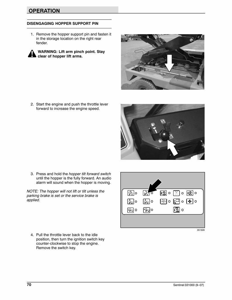
OPERATION
Sentinel 331000 (9−07)70
DISENGAGING HOPPER SUPPORT PIN
1. Remove the hopper support pin and fasten itin the storage location on the right rearfender.
WARNING: Lift arm pinch point. Stayclear of hopper lift arms.
2. Start the engine and push the throttle leverforward to increase the engine speed.
3. Press and hold the hopper tilt forward switchuntil the hopper is the fully forward. An audioalarm will sound when the hopper is moving.
NOTE: The hopper will not lift or tilt unless theparking brake is set or the service brake isapplied.
4. Pull the throttle lever back to the idleposition, then turn the ignition switch keycounter-clockwise to stop the engine.Remove the switch key.
351926
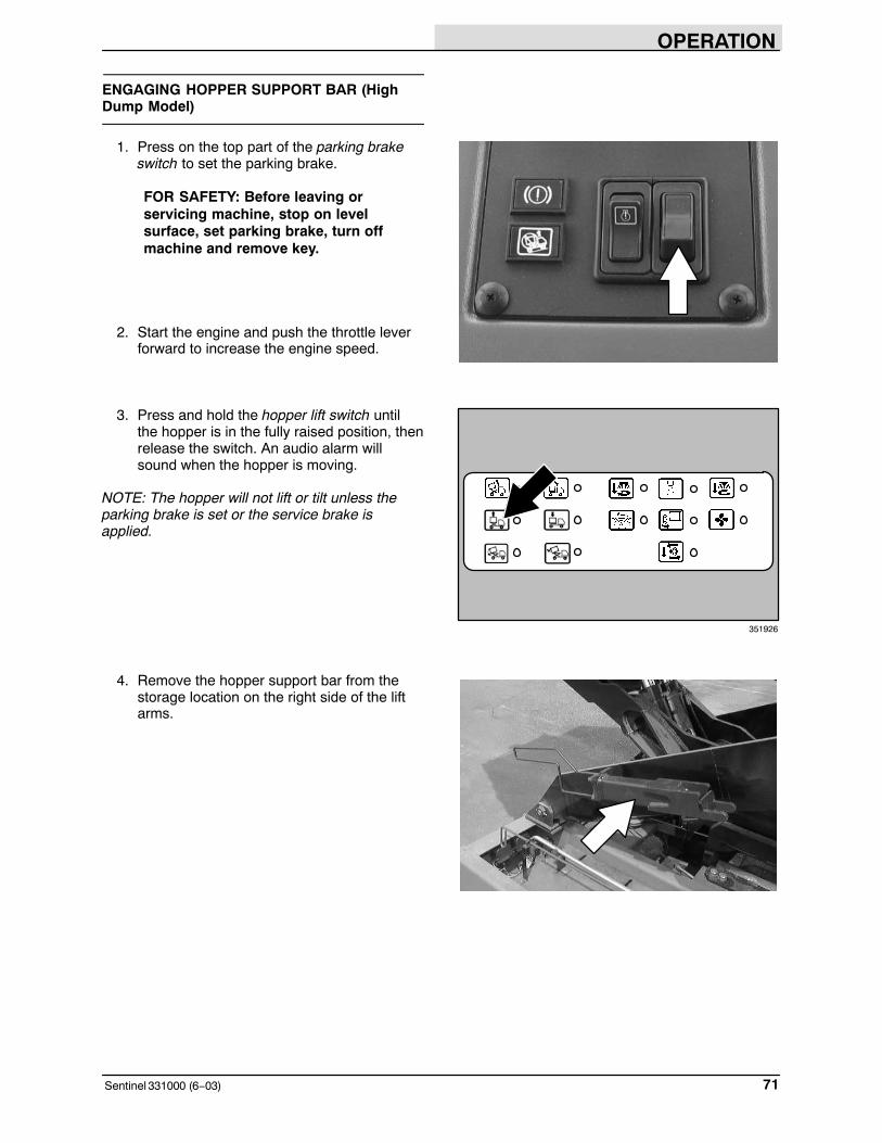
OPERATION
71Sentinel 331000 (6−03)
ENGAGING HOPPER SUPPORT BAR (HighDump Model)
1. Press on the top part of the parking brakeswitch to set the parking brake.
FOR SAFETY: Before leaving orservicing machine, stop on levelsurface, set parking brake, turn offmachine and remove key.
2. Start the engine and push the throttle leverforward to increase the engine speed.
3. Press and hold the hopper lift switch untilthe hopper is in the fully raised position, thenrelease the switch. An audio alarm willsound when the hopper is moving.
NOTE: The hopper will not lift or tilt unless theparking brake is set or the service brake isapplied.
4. Remove the hopper support bar from thestorage location on the right side of the liftarms.
351926

OPERATION
Sentinel 331000 (6−03)72
5. Install the support bar from the rear of themachine by first placing it behind thehorizontal bar of the lift arms.
WARNING: Raised hopper may fall.Engage hopper support bar.
6. Align the tabs of the support bar with theshaft of the lift arms. The longer tabs gotoward the front of the machine.
7. Place the base part of the support bar on topof the lift cylinders. Then release the bar.
8. Pull the throttle lever back to the idleposition, then turn the ignition switch keycounter-clockwise to stop the engine.Remove the switch key.

OPERATION
73Sentinel 331000 (9−07)
DISENGAGING HOPPER SUPPORT BAR (High Dump Model)
1. Remove the support bar from lift arms andfasten it in the storage location on the rightrear fender.
WARNING: Lift arm pinch point. Stayclear of hopper lift arms.
2. Start the engine and push the throttle leverforward to increase the engine speed.
3. Press and hold the hopper lower switch untilthe hopper is fully lowered, then release theswitch. An audio alarm will sound when thehopper is moving.
NOTE: The hopper will not lift or tilt unless theparking brake is set or the service brake isapplied.
4. Pull the throttle lever back to the idleposition, then turn the ignition switch keycounter-clockwise to stop the engine.Remove the switch key. 351926

OPERATION
Sentinel 331000 (6−03)74
OPERATION ON INCLINES
Drive the machine slowly on inclines and makesure your seat belt is fastened. Use the brakepedal to control machine speed on descendinginclines.
The maximum rated incline when driving themachine with the hopper down is 11� (20%).
Do not drive the machine on inclines with thehopper raised.
FOR SAFETY: Move machine with carewhen hopper is raised.
The incline light will come on when the machine ison an incline that is unsafe for high dumping thehopper. It will come on when the front to backincline is more than 11� (20%) and the side toside incline is more than 4�. The machine will nothigh dump when this light is on.

OPERATION
75Sentinel 331000 (6−06)
OPTIONS
VARIO SWEEPING BRUSH
The Vario Sweeping Brush allows side brushsweeping on the left or right side of the machine.The brush arm moves along the front of themachine. The brush angle, movement, front andside tilt, and direction of rotation are adjusted forthe right or left side.
NOTE: The brush arm is locked to the front of themachine during transport. Make sure to take thehair cotter pin from the lock pin before the brush isoperated.
WARNING: Brush linkage pinch points.Stay clear when linkage is moving.
1. Start the brush with the Vario SweepingBrush on−off switch. Push the right part ofthe switch to rotate the brushcounterclockwise. Push the left part of theswitch to rotate the brush clockwise.
2. Move the Vario Sweeping Brush from thestorage position with the joystick. Then useVario Sweeping Brush tilt/arm switch and thejoystick to move the brush to the desiredleft−right and up−down position.

OPERATION
Sentinel 331000 (6−06)76
3. Set the Vario Sweeping Brush tilt/arm switchto the sweeping brush arm position. Slide orswing the Vario Sweeping Brush to theright or left side of the machine as neededwith the Vario Sweeping Brush joystick .
4. Set the Vario Sweeping Brush tilt/arm switchto the brush tilt position and adjust the frontand side angle of the brush with the VarioSweeping Brush joystick.

OPERATION
77Sentinel 331000 (6−06)
WET DUST CONTROL SYSTEM
The wet dust control system is useful in dustyconditions to control the dust created by the sidebrushes and Vario Sweeping Brush. The systemconsists of a water tank, a water pump, and spraynozzles for each of the side brushes.
1. Press on the top part of the parking brakeswitch to set the parking brake and turn themachine off.
FOR SAFETY: Before leaving orservicing machine, stop on levelsurface, set parking brake, turn offmachine and remove key.
2. Fill the water tank. The fill spout is located inbehind the engine access door on the rightside of the machine.
WARNING: Flammable materials cancause explosion or fire. Do not useflammable materials in tank. Only usewater.
3. The water level can easily be seen on theside of the water tank. The water tank islocated behind the access door on the leftside of the machine.

OPERATION
Sentinel 331000 (6−03)78
4. Start the machine and turn on the waterpump with the water pump switch. The lightnext to the switch will come on.
5. Adjust the amount of water spray to each ofthe brushes with the water valve knobs. Turnthe water valve knob clockwise until itcomes to a complete stop to close the watersupply. If this is NOT done when themachine is shut off, water will continue toflow.
NOTE: The water pump switch needs to be onfor the water valves to operate.
6. The optional water tank low light will comeon when the water level is low in the tank.The water pump will shut off soon after thislight comes on.
NOTE: Do not use the water system on wetroads. Turn off the water pump and water valves.
351926

OPERATION
79Sentinel 331000 (6−03)
VACUUM WAND
The vacuum wand uses the machine’s vacuumsystem to allow the pick-up of debris that is out ofreach of the machine.
1. Press on the top part of the parking brakeswitch to set the parking brake.
FOR SAFETY: Before leaving orservicing machine, stop on levelsurface, set parking brake, turn offmachine and remove key.
2. Press and hold the hopper tilt back switchuntil the hopper is tilted enough to allow thevacuum door to open.
NOTE: The hopper will not lift or tilt unless theparking brake is set or the service brake isapplied.
3. Remove the vacuum wand door tool fromthe storage location on the right rear fender.
WARNING: Lift arm pinch point. Stayclear of hopper lift arms.
351926

OPERATION
Sentinel 331000 (3−05)80
4. Close the vacuum door with the vacuumwand door tool. Place the tool back in itsstorage location under the hopper.
WARNING: Conveyor throws debris.Conveyor pinch point. Stay clear whenin operation.
NOTE: Do not engage sweep mode while thevacuum wand door is covering the conveyoropening. Damage to the machine can occur.
5. Press and hold the hopper tilt forward switchuntil the hopper is fully forward.
NOTE: The hopper will not lift or tilt unless theparking brake is set or the service brake isapplied.
6. Press the vacuum fan switch to turn on thevacuum fan. The light next to the switch willcome on.
351926
351926

OPERATION
81Sentinel 331000 (9−07)
7. Move the throttle lever until the enginespeed is between 2300 − 2400 RPM.
WARNING: Machine can emit excessivenoise. Consult with your regulatoryagency for exposure limits. Hearing losscan result. Wear hearing protection.
8. Remove the wand from the hopper door andvacuum as required.
9. Place the vacuum wand back on the hopperdoor when finished.
10. Pull the throttle lever to the idle position.
11. Press the vacuum fan switch to turn off thevacuum fan. The light next to the switch willturn off.
12. Press and hold the hopper tilt back switchuntil the hopper is in the fully tilted position.
13. Open the vacuum door with the vacuumwand door tool. Place the tool back in thestorage location on the right rear fender.
WARNING: Lift arm pinch point. Stayclear of hopper lift arms.
14. Press and hold the hopper tilt forward switchuntil the hopper is fully forward.
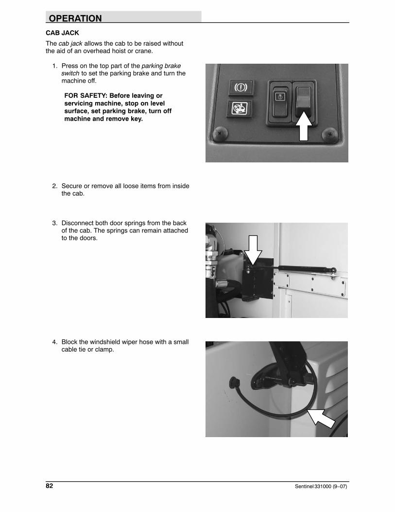
OPERATION
Sentinel 331000 (9−07)82
CAB JACK
The cab jack allows the cab to be raised withoutthe aid of an overhead hoist or crane.
1. Press on the top part of the parking brakeswitch to set the parking brake and turn themachine off.
FOR SAFETY: Before leaving orservicing machine, stop on levelsurface, set parking brake, turn offmachine and remove key.
2. Secure or remove all loose items from insidethe cab.
3. Disconnect both door springs from the backof the cab. The springs can remain attachedto the doors.
4. Block the windshield wiper hose with a smallcable tie or clamp.

OPERATION
83Sentinel 331000 (9−07)
5. Remove the hardware securing the rear ofthe cab.
6. Locate the cab jack handle near the left doorof the machine. Insert it into the cab jack,twist the handle clockwise, and pump thecab to the fully elevated position. Engagethe cab support bar.
WARNING: Raised cab may fall. Engagecab support bar.
7. To lower the cab, disengage the cab supportbar and twist the handle counter clockwise.
8. Reinstall the hardware to secure the cab,remove the cable tie from the windshieldwiper fluid hose, and reinstall both doorsprings to the back of the cab.

OPERATION
Sentinel 331000 (5−10)84
TILTING THE CAB (MANUALLY)
The cab can be tilted forward to accesscomponents under the cab. The cab must be tiltedmanually with an overhead hoist if the machine isnot equipped with the cab jack option.
CAUTION; DO NOT ATTEMPT TO TILTTHE CAB WITHOUT THE USE OF ANOVERHEAD MOTORIZED TROLLYHOIST.
FOR SAFETY: Before leaving orservicing machine, stop on levelsurface, set parking brake, and turn offmachine.
1. Secure or remove all loose items from insidethe cab.
2. Disconnect both door springs from the backof the cab. The springs can remain attachedto the doors.
3. Block the windshield wiper hose with a smallcable tie or clamp.

OPERATION
85Sentinel 331000 (5−10)
4. Remove the hardware securing the rear ofthe cab.
5. Attach a chain from the overhead hoist tothe hook on the top rear part of the cab. Tiltthe cab far enough to engage the cabsupport bar.
6. Align the lower hole of the support bar withthe machine frame, then engage the cabsupport bar by installing the pin into lowerhole.
WARNING: Raised cab may fall. Engagecab support bar.
7. Keep the chain from the overhead hoistattached as added support.

OPERATION
Sentinel 331000 (6−06)86
MACHINE TROUBLESHOOTING
Problem Cause Remedy
Machine does not start Directional lever in forward orreverse
Place directional lever in neutral
Glow plug not heated Heat glow plug
Fuel tank empty Fill fuel tank
Engine oil pressure too low Check engine oil level
Engine temperature too high Check coolant level
Excessive dusting Brush skirts and dust seals worn,damaged, out of adjustment
Replace or adjust brush skirts ordust seals
Hopper dust filter clogged Shake and/or clean or replacedust filter
Hopper not down completely Lower hopper completely
Hopper rear door open Close and latch hopper rear door
Vacuum wand door closed Open vacuum wand door
Vacuum fan not on Turn vacuum fan on
Vacuum fan failure Contact TENNANT service per-sonnel
Thermo Sentry tripped Reset Thermo Sentry
Water tank empty Fill water tank
Wet dust water pump or valvesnot turned on
Turn on the wet dust control waterpump and valves
Wet dust control filter clogged Clean or replace filter
Sweeping functions keep rais-ing and turning off
Engine speed too fast Reduce engine speed
Sweep switch will not activate Hopper raised or not fully forward Lower and move hopper fully for-ward
Engine throttle to high Decrease engine throttle
Hopper will not lift or tilt Machine on too steep of an incline Move machine to a level surface
Park or service brake not applied Apply park or service brake
Hopper overloaded Remove debris from hopper
Engine throttle too low Increase engine throttle
Machine will not propel Brake pressure too low Contact service personnel
Operator not in seat Sit in seat
Parking brake on Release parking brake
Directional lever in neutral Move directional lever in forwardor reverse position
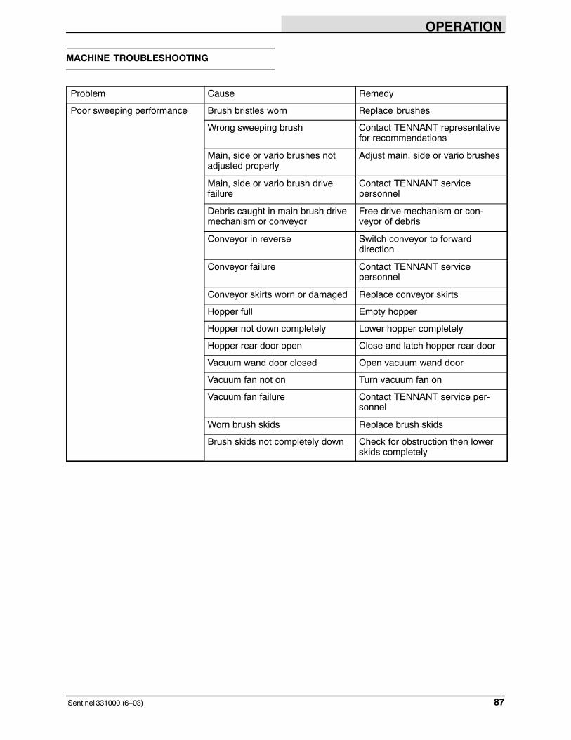
OPERATION
87Sentinel 331000 (6−03)
MACHINE TROUBLESHOOTING
Problem Cause Remedy
Poor sweeping performance Brush bristles worn Replace brushes
Wrong sweeping brush Contact TENNANT representativefor recommendations
Main, side or vario brushes notadjusted properly
Adjust main, side or vario brushes
Main, side or vario brush drivefailure
Contact TENNANT servicepersonnel
Debris caught in main brush drivemechanism or conveyor
Free drive mechanism or con-veyor of debris
Conveyor in reverse Switch conveyor to forwarddirection
Conveyor failure Contact TENNANT servicepersonnel
Conveyor skirts worn or damaged Replace conveyor skirts
Hopper full Empty hopper
Hopper not down completely Lower hopper completely
Hopper rear door open Close and latch hopper rear door
Vacuum wand door closed Open vacuum wand door
Vacuum fan not on Turn vacuum fan on
Vacuum fan failure Contact TENNANT service per-sonnel
Worn brush skids Replace brush skids
Brush skids not completely down Check for obstruction then lowerskids completely

MAINTENANCE
Sentinel 331000 (11−09)88
MAINTENANCE
2
1
158
7
6
1812
14
13
5
17
4
1011
3
16
9
7
NOTE: Numbered references for maintenance chart pages 87, 88.

MAINTENANCE
89Sentinel 331000 (3−05)
MAINTENANCE CHART
Interval Key Description ProcedureLubricant/
Fluid
No. ofServicePoints
Daily 10 Conveyor Check chain and ratchetts − 2Lubricate chain EO 2Wash internally − 1Lubricate bearings WBG 4
10 Conveyor skirts and paddles Check for damage and wear − All16 Engine air intake screen Check and clean − 13 Engine crankcase Check oil level EO 13 Fuel water separator Check for water, drain − 13 Radiator Check and clean core exterior − 1
Check coolant level in overflowreservoir
WG 1
3 Hydraulic fluid cooler Check and clean cooler fins − 13 Air conditioner condenser
(option)Check and clean cooler fins − 1
11 Hydraulic fluid reservoir Check fluid level HYDO 19 Brush compartment skirts Check for damage and wear − 3
Main brush Check for damage, wear, andadjustment
− 1
Check brush pattern − 1Lubricate support rods − 1
12 Side brush(es) Check for damage and wear − 1−34 Hopper dust filter Shake − 1
13 Windshield washer reservoir Check fluid level WF 150 Hours 3 Fuel lines and clamps Check for tightness and wear − 1
7 Tires Check pressure − 48 Steering Check wheel alignment 1
17 Cab filters Clean − 11 Main brush/conveyor lift Purge hydraulic fluid air − 1
100 Hours 9 Brush compartment, convey-or and hopper seals, skidflap
Check for damage or wear − All
3 Alternator/fan belt Check tension − 13 Air conditioner belt (option) Check tension − 13 Engine air filter Check the dust cap − 16 Hopper tilt Lubricate WBG 86 Hopper lift (option) Lubricate WBG 137 Wheels Check wheel nut torque − 4
18 Skids Check for wear − 2

MAINTENANCE
Sentinel 331000 (5−10)90
Interval Key Description ProcedureLubricant/
Fluid
No. ofServicePoints
200 Hours 3 Radiator hoses and clamps Check for tightness and wear − 28 Steering Lubricate steering cylinder WBG 28 Suspension Lubricate leaf springs and pivots WBG 16
14 Vario sweeping brush Lubricate rotation and guides WBG 212 Side brush(es) Lubricate pivot WBG 27 Tires Check wear and rotate − 4− Hydraulic hoses Check for wear and damage − All2 Battery **Clean and tighten battery cable
connections− 1
8 Wet dust control system(option)
Clean water filter − 1
5 Windshield wiper blades Check for wear − 2250 Hours 3 Engine crankcase **Change oil and filter element EO 1
3 Fuel filter Replace − 1400 Hours 15 Differential Check oil level − 1
7 Service brakes Check fluid level − 4800 Hours 11 Hydraulic reservoir Replace filler cap − 11000Hours
3 Engine valves Valve lash adjustment − 1
1200Hours
16 Hydraulic fluid filter * Change filter element − All
1600Hours
15 Differential Change gear lubricant GL 17 Service brakes Change fluid level UTF 43 Cooling system Flush WG 1
2400Hours
15 Hydraulic fluid reservoir * Replace suction strainer − 1* Change hydraulic fluid HYDO 1
NOTE: Change the hydraulic fluid, filter, and suction strainer, indicated (*), after every 800 hours formachines NOT originally equipped with TennantTrue premium hydraulic fluid. (See Hydraulics section).
NOTE: Also check procedures indicted (**) after the first 50-hours of operation, and procedures indicated(**) after the first 250 hours of operation.
LUBRICANT/FLUID
UTF Universal tractor fluid (Mobil 424). . .EO Engine oil, API diesel classification CG4 or better. . . .HYDO TennantTrue premium hydraulic fluid or equivalent.WBG Waterproof bearing grease (TENNANT part no. 765819). .WG Distilled water, coolant conditioner (TENNANT part no. 770172) and permanent-type ethylene . . .
glycol anti-freeze, −34� C (−30� F)WF Automotive-type windshield washer fluid. . . .GL SAE 90 weight gear lubricant (Grade GL5). . . .
NOTE: More frequent intervals may be required in extremely dusty conditions.

MAINTENANCE
91Sentinel 331000 (11−09)
LUBRICATION
A
C
G
L
H
D DE
E
EE
J
H
B
CF
K
I
351930
NOTE: Lettered references for lubrication section of manual pages 89 thru 94.

MAINTENANCE
Sentinel 331000 (6−03)92
A. HOPPER TILT (LOW DUMP)
The hopper tilt has eight grease fittings. Fourgrease fittings are located on the tilt cylinders, oneon each end of the two cylinders. Two greasefittings are located on the hopper safety supportcylinders, one at each end. The last two greasefittings are located at the hopper tilt pivot, one oneach side. Lubricate these fittings with WaterproofBearing grease (TENNANT part no. 765819) afterevery 100 hours of operation.
WARNING: Raised hopper may fall.Engage hopper support pin.
B. HOPPER LIFT/TILT (HIGH DUMP OPTION)
The high dump hopper lift has thirteen greasefittings. Four grease fittings are located on theupper tilt cylinders, one on each end of the twocylinders. Two grease fittings are located on thelower lift cylinders, one at each base. One greasefitting is located at the top of the hopper safetysupport cylinder. Two grease fittings are located atthe hopper tilt pivot, one on each side. The lastfour grease fittings are located on the cross shaftpivots of the hopper lift arms, one at each of thefour pivots. Lubricate these fittings withWaterproof Bearing grease (TENNANT part no.765819) after every 100 hours of operation.
WARNING: Raised hopper may fall.Engage hopper support bar.
C. AXLE LEAF SPRINGS
The axle leaf springs have twelve grease fittings.Lubricate with Waterproof Bearing grease(TENNANT part no. 765819) after every 200hours of operation.
351933
351932

MAINTENANCE
93Sentinel 331000 (6−03)
D. STEERING CYLINDER
Each steering cylinder has one grease fitting.Lubricate with Waterproof Bearing grease(TENNANT part no. 765819) after every 200hours of operation.
E. WHEEL PIVOTS POINTS
The wheel pivots points have eight grease fittings.Lubricate with Waterproof Bearing grease(TENNANT part no. 765819) after every 200hours of operation.
F. SIDE BRUSH PIVOT
Each side brush pivot has a grease fitting.Lubricate with Waterproof Bearing grease(TENNANT part no. 765819) after every 200hours of operation.

MAINTENANCE
Sentinel 331000 (6−06)94
G. VARIO SWEEPING BRUSH (OPTION)
The brush pivot has two grease fittings. Lubricatewith Waterproof Bearing grease (TENNANT partno. 765819) after every 200 hours of operation.
H. CONVEYOR BEARINGS
There are four bearing grease fittings. Lubricatedaily with Waterproof Bearing grease (TENNANT part no. 765819).

MAINTENANCE
95Sentinel 331000 (6−03)
I. CONVEYOR CHAIN
The conveyor chains should be lubricated withengine oil daily.
Remove the access covers on the sides of theconveyor. Run the conveyor in reverse at idle. Oilthe chain making sure to lubricate the o-rings onthe chain. Put the access covers back on thesides of conveyor.
FOR SAFETY: When servicing machine,avoid moving parts. Do not wear loosejackets, shirts, or sleeves.
J. ENGINE
Check the engine oil level daily. The engine oildipstick can be accessed behind the right sideengine access door.
Change the engine oil and oil filter after the first50 hours of operation, then after every 250 hoursof machine operation after that. Use 10W30 APICG4/CH4, ACEA E3/E5 rated engine oil.
The engine oil drain is accessed through the rightside door.
Fill the engine with oil to the level indicated on theoil dipstick. The engine oil capacity is 11.7 L (12.4 qt) including the oil filter.
FOR SAFETY: When servicing machine,avoid moving parts. Do not wear loosejackets, shirts, or sleeves.

MAINTENANCE
Sentinel 331000 (6−03)96
K. DIFFERENTIAL
Check the lubricant level in the differential afterevery 400 hours of operation by removing the fillerplug.
Change the differential lubricant after every 1600hours of operation. Use SAE 90 weight gearlubricant.
L. MAIN BRUSH SUPPORT RODS
The main brush support rods have a total of eightgrease fittings, four on each side. Lubricate withWaterproof Bearing grease (TENNANT part no.765819) daily.

MAINTENANCE
97Sentinel 331000 (5−10)
HYDRAULICS
HYDRAULIC FLUID RESERVOIR
The reservoir is located on the right side of themachine next to the engine.
Check the hydraulic fluid level at operatingtemperature daily. Make sure the hopper is downwhen checking hydraulic fluid level. The sightgauge is marked with full, the black line, and add,the red line, levels to indicate the level of hydraulicfluid in the reservoir.
ATTENTION! Do not overfill thehydraulic fluid reservoir or operate themachine with a low level of hydraulicfluid in the reservoir. Damage to themachine hydraulic system may result.
Mounted on top of the reservoir is a filler cap witha built-in breather. Replace the cap after every800 hours of operation.
Lubricate the filler cap gasket with a film ofhydraulic fluid before putting the cap back on thereservoir.
Drain and refill the hydraulic fluid reservoir withnew TennantTrue premium hydraulic fluid afterevery 2400 hours of operation. Machines have ablue colored drop (left photo) on the hydraulic fluidlabel if originally equipped with TennantTruepremium hydraulic fluid.
TennantTrue Fluid Previous Fluid
NOTE: Change the hydraulic fluid, filter, andsuction strainer after every 800 hours for ALLmachines that have NOT consistently usedTennantTrue premium hydraulic fluid orequivalent.
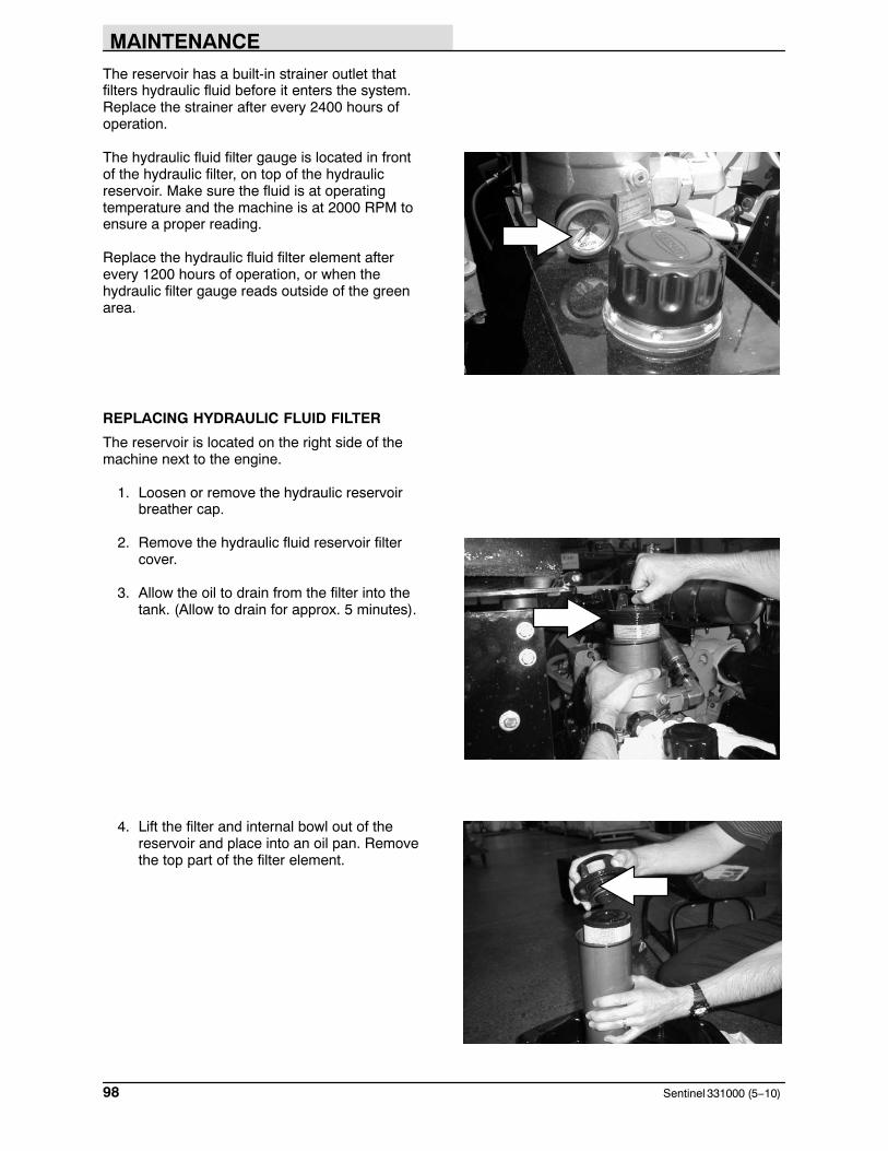
MAINTENANCE
Sentinel 331000 (5−10)98
The reservoir has a built-in strainer outlet thatfilters hydraulic fluid before it enters the system.Replace the strainer after every 2400 hours ofoperation.
The hydraulic fluid filter gauge is located in frontof the hydraulic filter, on top of the hydraulicreservoir. Make sure the fluid is at operatingtemperature and the machine is at 2000 RPM toensure a proper reading.
Replace the hydraulic fluid filter element afterevery 1200 hours of operation, or when thehydraulic filter gauge reads outside of the greenarea.
REPLACING HYDRAULIC FLUID FILTER
The reservoir is located on the right side of themachine next to the engine.
1. Loosen or remove the hydraulic reservoirbreather cap.
2. Remove the hydraulic fluid reservoir filtercover.
3. Allow the oil to drain from the filter into thetank. (Allow to drain for approx. 5 minutes).
4. Lift the filter and internal bowl out of thereservoir and place into an oil pan. Removethe top part of the filter element.

MAINTENANCE
99Sentinel 331000 (9−2014)
5. Pour out any residual oil into the oil pan.
6. Remove and replace the filter element.
7. Replace the new filter element and internalbowl assembly back into the hydraulic fluidreservoir.
HYDRAULIC FLUID
There are two fluids available for differenttemperature ranges:
TennantTrue premium hydraulic fluid (Extended Life)
Partnumber
Ambient airtemperature
ISOGradeViscosityIndex(VI)
Ca-pacity
1057707 all temperatures ISO 32VI 163 orHigher
3.8 L(1 gal)
1057708 all temperatures ISO 32VI 163 orHigher
19 L (5 gal)
9000119Synthetic
all temperatures ISO 68VI 158
19 L (5 gal)

MAINTENANCE
Sentinel 331000 (NIL)100
If using a locally−available hydraulic fluid, be surethe specifications match the Tennant hydraulicfluid specifications. Substitute fluids can causepremature failure of hydraulic components.
Synthetic fluids offer several advantages.Synthetic fluids can operate in a wider range ofextreme temperatures. This feature isadvantageous in states with wide seasonaltemperature changes.
NOTE: DO NOT Mix Synthetic HydraulicFluid With TENNANT TRUE PremiumHydraulic Fluid.
ATTENTION! Hydraulic componentsdepend on system hydraulic fluid forinternal lubrication. Malfunctions,accelerated wear, and damage will resultif dirt or other contaminants enter thehydraulic system.

MAINTENANCE
101Sentinel 331000 (6−06)
HYDRAULIC HOSES
Check the hydraulic hoses every 200 hours ofoperation for wear or damage.
Fluid escaping at high pressure from a very smallhole can be almost invisible, and can causeserious injuries.
See a doctor at once if injury results fromescaping hydraulic fluid. Serious infection orreaction can develop if proper medical treatmentis not given immediately.
FOR SAFETY: When servicing machine,use cardboard to locate leakinghydraulic fluid under pressure.
If you discover a fluid leak, contact yourmechanic/supervisor.
PURGING AIR FROM THE HYDRAULICCONVEYOR LIFT SYSTEM
If a hydraulic component in the lift system hasbeen replaced, air will get into the hydraulic fluid.This air must be purged from the system.
Purge air from the hydraulic system after ahydraulic component in the lift system has beenchanged. To purge air from the hydraulic system,start the machine and press the sweep switch tolower the conveyor. Leave the machine in thesweep mode and shut off the machine to collapsethe lift cylinders. Turn the ignition switch to ON,but do not start the engine. Press the sweepswitch to activate solenoid valve (SV31) on thecontrol block, allowing hydraulic fluid to flowthrough the valve. Disconnect the hose from thetop fitting of the right lift cylinder and drain thehydraulic fluid into a pan to purge air from thehose. Reconnect the hose to the right lift cylinder.Disconnect the hose from the top fitting of the leftlift cylinder and drain the hydraulic fluid into a panto purge air from the hose. Reconnect the hose tothe left lift cylinder. Start the engine and checkhydraulic system for leaks. Cycle the sweep modeand observe the conveyor lift for proper operation.
00002
351926

MAINTENANCE
Sentinel 331000 (6−03)102
ENGINE
COOLING SYSTEM
Check the radiator coolant level daily in theoverflow reservoir. Use distilled water mixed witha permanent-type, ethylene glycol antifreeze to a−34� C (−30� F) rating. Add coolant to theoverflow reservoir. Add one pint of conditioner(TENNANT part no. 770172) to each coolantchange.
FOR SAFETY: When servicing machine,avoid contact with hot engine coolant.
Check the radiator hoses and clamps every 200 hours of operation. Tighten the clamps if theyare loose. Replace the hoses and clamps if thehoses are cracked, harden, or swollen.
Check the radiator core exterior and hydrauliccooler fins for debris daily. If the machine isequipped with air conditioning, check thecondenser as well. The condenser hinges out forcleaning. Blow or rinse all dust, which may havecollected on the radiator or condenser, in throughthe grille and radiator fins, opposite the directionof normal air flow. Be careful not to bend thecooling fins when cleaning. Clean thoroughly toprevent the fins becoming encrusted with dust.Clean the radiator, cooler, and condenser onlyafter they have cooled to avoid cracking.
FOR SAFETY: When using pressurizedair or water, wear eye and earprotection.
ATTENTION! Do not wash the fuelinjection pump or turbocharger whenthe engine is running or warm. Thiscould damage these components.
Flush the radiator and the cooling system every1600 hours of operation, using a dependablecleaning compound. Add one pint of conditioner(TENNANT part no. 770172) to each coolantchange.

MAINTENANCE
103Sentinel 331000 (6−03)
AIR FILTER
The engine air filter housing has an end cap, arubber dust cap and a dry cartridge-type air filterelement. Check the dust cap every 100 hours ofoperation to make sure it is expelling dust.Replace the dust cap if the rubber is worn.
The air filter element must be replaced wheneverit is damaged. Inside the air filter element is asafety element. Replace this element, do notclean it, after the regular element has beendamaged or changed three times.
Replace the air filter element only when theclogged engine air filter light shows restriction inthe air intake system. Do not remove the air filterelement from the housing unless it is restricting airflow.
On standard engines, install the end cap on theair filter housing with the rubber dust cap facingdownward. On turbo engines, the dust cap is onthe housing.

MAINTENANCE
Sentinel 331000 (6−03)104
AIR INTAKE SCREEN
Check the air intake screen for obstructions daily.It is located on top of the engine air cleaner.
FUEL FILTER
The fuel filter has an element that filters impuritiesfrom the diesel fuel. It is located on the conveyorside of the engine.
Replace the fuel filter element after every 250hours of operation.
FOR SAFETY: Keep flames and sparksaway from fuel system service area.Keep area well ventilated.
FUEL WATER SEPARATOR
The fuel water separator separates water from thediesel fuel. It is located on the bottom of the fuelfilter.
Open the separator daily to allow anyaccumulated water to drain out.

MAINTENANCE
105Sentinel 331000 (11−09)
FUEL LINES
Check the fuel lines every 50 hours of operation.If the clamp band is loose, apply oil to the screwof the band, and securely tighten the band.
The fuel lines are made of rubber, and maybecome worn out whether the engine has beenused much or not. Replace the fuel lines andclamp bands every two years.
FOR SAFETY: Keep flames and sparksaway from fuel system service area.Keep area well ventilated.
If the fuel lines and clamp bands are found wornor damaged before two years’ time, replace orrepair them at once. When the fuel lines are notinstalled, plug both ends with clean cloth or paperto prevent dirt from entering the lines. Dirt in thelines can cause fuel injection pump malfunction.
ENGINE VALVE
Engine valve lash adjustment is required after thefirst 250 hours of operation, then after every 1000hours of operation after that. Allow the valves tocool before checking valves.
Refer to the manufacturer’s maintenance manual.

MAINTENANCE
Sentinel 331000 (6−03)106
CAB FILTERS
The fresh air cab filters are located in the front ofthe cab.
WARNING: Brush linkage pinch points.Stay clear when linkage is moving.
Clean these filters with soap and water. Checkand clean the cab filters after every 50 hours ofoperation. Replace when necessary.
WET DUST CONTROL FILTER (OPTION)
The wet dust control filter is located under the cabbetween the front wheels.
Clean the water filter every 200 hours ofoperation by removing it and flushing it with cleanwater.

MAINTENANCE
107Sentinel 331000 (6−03)
WINDSHIELD WIPER BLADES
Check the windshield wiper blades for wear every200 hours of operation. Replace when necessary.
WINDSHIELD WASHER FLUID
The windshield washer fluid is located behind theoperator cab and can be accessed through theright engine access door. Check the windshieldwasher fluid level daily. Fill with automotive-typewindshield washer fluid.
BATTERY
The battery is located behind the operator caband can be accessed through the right engineaccess door.
After the first 50 hours of operation, and every200 hours after that, clean and tighten the batteryconnections.
FOR SAFETY: When servicing machine,avoid contact with battery acid. Weareye and ear protection.
NOTE: When the battery is disconnected, theparking brake will come on automatically.
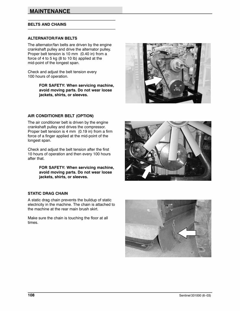
MAINTENANCE
Sentinel 331000 (6−03)108
BELTS AND CHAINS
ALTERNATOR/FAN BELTS
The alternator/fan belts are driven by the enginecrankshaft pulley and drive the alternator pulley.Proper belt tension is 10 mm (0.40 in) from aforce of 4 to 5 kg (8 to 10 lb) applied at themid-point of the longest span.
Check and adjust the belt tension every 100 hours of operation.
FOR SAFETY: When servicing machine,avoid moving parts. Do not wear loosejackets, shirts, or sleeves.
AIR CONDITIONER BELT (OPTION)
The air conditioner belt is driven by the enginecrankshaft pulley and drives the compressor.Proper belt tension is 4 mm (0.19 in) from a firmforce of a finger applied at the mid-point of thelongest span.
Check and adjust the belt tension after the first 10 hours of operation and then every 100 hoursafter that.
FOR SAFETY: When servicing machine,avoid moving parts. Do not wear loosejackets, shirts, or sleeves.
STATIC DRAG CHAIN
A static drag chain prevents the buildup of staticelectricity in the machine. The chain is attached tothe machine at the rear main brush skirt.
Make sure the chain is touching the floor at alltimes.

MAINTENANCE
109Sentinel 331000 (6−03)
DEBRIS HOPPER
HOPPER DUST FILTER
The hopper dust filter filters the air pulled up fromthe hopper. The dust filter is equipped with ashaker to remove the accumulated dust particles.To clean the dust filter, with the engine in the idleposition, press the filter shaker switch.
Shake the dust filter before tilting or dumping thehopper and at the end of every work shift. Whensweeping in dusty conditions, shake the filtermore often.
Filters may become plugged up with mud andheavy material when sweeping in wet conditions.Light fiberous material can also become inbeddedin between the filter pleats.
TO CLEAN THE HOPPER DUST FILTER
1. Stop the engine and set the machine parkingbrake.
2. Tip the hopper back and release the hopperdoor.
3. Secure the door with the door support cable.
4. Use a garden hose or broom to clean thehopper filter from the inside of the hopper.
TO REMOVE OR REPLACE HOPPER DUSTFILTER
1. Stop the engine and set the machine parkingbrake.
FOR SAFETY: Before leaving orservicing machine, stop on levelsurface, set parking brake, turn offmachine and remove key.
2. Remove the top hopper cover.
3. Remove the nuts holding the filter shakerframe in the hopper.
4. Pull the filter shaker frame and filter out ofthe hopper.
5. Drill out the rivets holding the filter to theshaker frame.
351931

MAINTENANCE
Sentinel 331000 (6−06)110
6. Put the new separators into the new filterbag pockets.
7. Take the rods out of the old filter, and putthem in the new filter.
8. Put the filter into the shaker frame.
9. Stretch the filter over the edges of theshaker frame. Pull the drawstring tight.
10. Drill and rivet the filter to the shaker frame.
11. Put the filter shaker frame and filter in thehopper.
12. Install the retaining nuts for the filter shakerframe and tighten.
13. Check the seals on the top hopper coverand the hopper. Replace any that is worn ordamaged.
14. Put the top hopper cover back on thehopper. Make sure the cover has a goodseal before tightening the hardware.
THERMO SENTRY
The Thermo Sentry senses the temperature of theair pulled up from the hopper. It is located at therear of the hopper. If the air temperature in thehopper reaches 71° ± 3° C (160° ± 5° F), theThermo Sentry stops the vacuum fan and cuts offthe air flow. The sweeping functions will stop, thebrushes will raise and the vacuum fan icon willstart blinking.
The Thermo Sentry will automatically reset whenthe air temperature in the hopper falls below 60° ±3° C (140° ± 5° F).

MAINTENANCE
111Sentinel 331000 (6−03)
CONVEYOR
The conveyor transports debris picked up by themain brush to the hopper, by means of a paddlesystem. Check tension, clean and lubricate theconveyor chain daily. To lubricate, refer to theConveyor Chain in the Lubrication section of thismanual.
The conveyor chain is tensioned automaticallywhile operating, with the hydraulic cylinders.When the sweeping system is turned off, theconveyor is equipped with a locking ratchetmechanism to keep the conveyor chain fromdisengaging the drive sprockets.
As the conveyor chain wears, the locking ratchetmechanisms move up the pins mounted on theslide rails on both sides of the machine. Clean theratchet mechanisms daily. Check the ratchet tipsand pins for damage and wear daily.
Check the conveyor skirts and paddles fordamage and wear daily.
WARNING: Conveyor throws debris.Conveyor pinch point. Stay clear whenin operation.
Clean the conveyor thoroughly with a garden hosedaily. To do this, tilt the hopper back engage thehopper tilt support bar, and turn the machinepower off. Remove the top conveyor panel fromrear of the conveyor to access the inside of theconveyor.
FOR SAFETY: When servicing machine,wear eye and ear protection when usingpressurized air or water.

MAINTENANCE
Sentinel 331000 (11−09)112
BRUSHES
MAIN BRUSH
The main brush is cylindrical and spans the widthof the machine, sweeping debris into theconveyor, which deposits the debris into thehopper.
Check the brush daily for wear or damage.Remove any string or wire tangled on the mainbrush, main brush drive hub, or main brush idlerhub.
Check the main brush pattern daily. Refer to theTO CHECK AND ADJUST MAIN BROOMPATTERN section of the manual. The patternshould be 100 to 125 mm (4 to 5 in) wide. Adjustthe main brush pattern with the main brush downpressure nut located under the hopper.
Replace the brush when it no longer cleanseffectively.
TO REPLACE MAIN BRUSH
1. Park the machine on level ground and setthe machine parking brake.
2. Press the sweep switch to lower the mainbrush.
3. Stop the engine.
FOR SAFETY: Before leaving orservicing machine, stop on levelsurface, set parking brake, turn offmachine and remove key.
4. Remove the right side main brush accessdoor.
351926
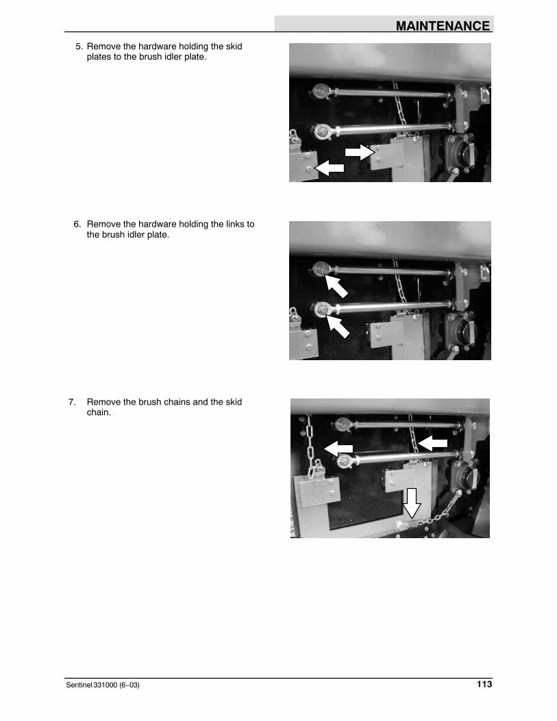
MAINTENANCE
113Sentinel 331000 (6−03)
5. Remove the hardware holding the skidplates to the brush idler plate.
6. Remove the hardware holding the links tothe brush idler plate.
7. Remove the brush chains and the skidchain.

MAINTENANCE
Sentinel 331000 (6−03)114
8. Remove the hardware holding the idler plateonto the machine.
9. Remove the brush idler plate.
10. Grasp the main brush; pull it off the brushdrive plug and out of the main brushcompartment.
11. Put the new brush on the ground next to theaccess door.
12. Slide the main brush onto the drive plug.Rotate the brush until it engages the driveplug, and push it all the way onto the plug.
13. Slide the main brush idler plate plug onto themain brush.
14. Mount the idler plate onto the machine withthe hardware removed earlier.
15. Mount the brush chains and the skid chain.
16. Mount the links to the idler plate with thehardware removed earlier.
17. Mount the skid plates to the idler plate withthe hardware removed earlier.
18. Put the right side main brush access doorback on the machine.
19. Check and adjust the main brush pattern.

MAINTENANCE
115Sentinel 331000 (6−03)
TO CHECK AND ADJUST MAIN BRUSHPATTERN
1. Park the machine on level ground and setthe machine parking brake.
2. Press the sweep switch to lower and startthe main brush. Allow the brush to rotate inone place for 2 minutes.
3. Press the sweep switch again to raise andstop the main brush.
4. Drive the machine off the test area.
5. Observe the width of the brush pattern. Theproper brush pattern width is 100 to 125 mm(4 to 5 in) along the entire length of thebrush pattern.
6. To increase the width of the main brushpattern, turn the main brush down pressurenut counter-clockwise.
To decrease the width of the main brushpattern, turn the main brush down pressurenut clockwise.
351926

MAINTENANCE
Sentinel 331000 (11−09)116
SIDE BRUSH
The side brush sweeps debris along edges intothe path of the main brush.
Check the brush daily for wear or damage.Remove any string or wire found tangled on theside brush or side brush drive hub.
The side brush pattern is set at the factory.
Replace the brush when it no longer cleanseffectively.
TO REPLACE SIDE BRUSH
1. Raise and stop the side brush.
2. Stop the engine and set the machine parkingbrake.
FOR SAFETY: Before leaving orservicing machine, stop on levelsurface, set parking brake, turn offmachine and remove key.
3. Remove the dry dust control skirt assembly(option) if equipped.
4. Remove the side brush retaining hardwareholding the brush to the drive hub.
WARNING: Side brush can move. Donot step on side brush.
5. Mount the new side brush to the drive hubwith the hardware removed earlier.
6. Check the sidebrush linkage for wear andloose hardware.

MAINTENANCE
117Sentinel 331000 (6−03)
SKIRTS AND SEALS
BRUSH ACCESS DOOR SKIRTS
The brush access door skirts are located on thebottom and front of each of the two main brushaccess doors. The bottom skirts should touch theskid plates on either side of the machine.
Check the skirts for wear or damage daily.
DRY DUST CONTROL SKIRTS (OPTION)
The dry dust control skirts (option) are mountedover the side brushes on each side of themachine. The skirts should clear the ground byless than 3 mm (0.125 in).
Check the skirts for wear or damage daily.
BRUSH COMPARTMENT REAR SKIRT
The brush compartment skirt is located at the rearof the brush compartment. The skirt should clearthe ground by 3 mm (0.125 in).
Check the skirt for wear or damage daily.
NOTE: Tire pressure and a full hopper will affectskirt clearances.

MAINTENANCE
Sentinel 331000 (6−03)118
CONVEYOR SKIRTS
The conveyor has a lip skirt located at the bottomrear of the conveyor and two side skirts. Theskirts should touch the ground when the conveyoris lowered into the sweeping position.
Check the skirts for wear or damage daily.
Replace the skirts when they no longer touch theground.
NOTE: Tire pressure and a full hopper will affectskirt clearances.
DOOR SEALS
The brush access doors have seals located alongtheir door edges.
Check the seals for wear or damage every 100 hours of operation.
The cab doors have seals located along their dooredges.
Check the seals for wear or damage every 100 hours of operation.

MAINTENANCE
119Sentinel 331000 (6−03)
CONVEYOR SEALS
The conveyor seals are located on the machineframe where the conveyor makes contact with theframe.
Check the seals for wear or damage every 100 hours of operation.
HOPPER SEALS
The hopper seals are located on the hopper door,the hopper filter cover, the dust filter, and the frontopening of the hopper.
Check the seals for wear or damage every 100 hours of operation.

MAINTENANCE
Sentinel 331000 (6−03)120
SKIDS
SKIDS
The skids are located on either side of the brushcompartment. They skim the ground when theconveyor is lowered into the sweeping positionand are designed to contain debris between themain brush and the conveyor lip.
Check the skids for wear after every 100 hours ofoperation. The skids should be replaced when thethickness is less than 1 mm (0.04 in).
The skids are attached to the upper plate bymeans of a rubber gusset that absorbs shock.Check the rubber gussets every 100 hours ofoperation for damage or wear.
BRAKES AND TIRES
SERVICE BRAKES
This machine is equipped with wet multi−discservice brakes located on all four wheels. Thesebrakes are filled with universal tractor fluid (Mobil 424). The fill/check ports are located on theside of the wheel hubs. The drain ports arelocated on the bottom of the wheel hubs. The fluidlevel should be checked after every 400 hours ofoperation. Change the fluid after every 1600 hoursof operation.
PARKING BRAKE
The parking brake is set with the parking brakeswitch. The dry multi−disk brake unit is locatedbetween the differential and the propelling motor.

MAINTENANCE
121Sentinel 331000 (6−06)
TIRES
The machine tires are pneumatic. The wheelsconsist of a 3-piece rim, flap, tube and tire.
Check the tire pressure every 50 hours ofoperation. The proper tire air pressure is:
bias ply tire 930−1000 kPa (135−145 psi)radial tire 930−1000 kPa (135−145 psi)
NOTE: The machine is equipped with 3-piecerims. If the tire pressure falls below 550 kPa (80 psi), the tire and wheel assembly should bebrought to an industrial tire service center forrepair and/or refilling.
Check the tires for wear and rotate every 200hours of operation.
WHEEL ALIGNMENT
When the machine has been used for some time,a number of things can cause the steering systemfrom tracking properly. Large temperature swings,continual turning in only one direction and cylinderleakage. The front axle is equipped with ahydraulic valve for aligning the wheels. Thisshould be done after every 50 hours of operationor when the machine is not tracking properly.
To align the wheels, start the machine and whilemoving slowly forward, turn the steering wheelfully right. Stop and apply the parking brake. Findthe red valve handle and place it on the steeringvalve located on the front axle. Open the valve byturning the handle 90� in the counter-clockwisedirection. Release the parking brake and whileslowly moving forward turn the steering wheel fullleft then full right. Stop, set the parking brake andclose the valve by turning the handle 90� in theclockwise direction.
NOTE: It is important for the machine to bemoving while turning so that there is no wind upon the side wall of the tires.
Remove the red valve handle and store for futureuse. Drive the machine straight forward 100−200 ftbefore turning. This will settle the system.
WHEEL NUTS
Check the wheel nut torque on the four wheelsevery 100 hours of operation. The proper torqueis 260 − 305 Nm (190 − 225 ft lb).

MAINTENANCE
Sentinel 331000 (6−03)122
PUSHING, TOWING, AND TRANSPORTINGTHE MACHINE
PUSHING OR TOWING THE MACHINE
If the machine becomes disabled, it can bepushed from the rear or pulled from the front.
The propelling pump has bypass valves to preventdamage to the hydraulic system when themachine is being pushed or towed. The ignitionswitch must be turned to the on position torelease the parking brake before pushing ortowing. DO NOT exceed 1.6 kmh (1 mph) or 30meters (100 feet) in distance when moving themachine. The bypass feature is to be used incase of machine breakdown. DO NOT move themachine for any great distance or damage willoccur to the propel pump even though the bypassvalves are engaged.
ATTENTION! Do not push or towmachine for a long distance and withoutusing the bypass valve, or the machinehydraulic system may be damaged.
Loosen the nuts on the by-pass valves with a 13 mm wrench. Turn in the set screws with a 4 mm allen wrench until they are below thesurface of the nut. Tighten the nuts.
When finished pushing or towing, loosen the nutson the bypass valves with a 13 mm wrench. Turnout the set screws with a 4 mm allen wrench untilthey top out. Tighten the nuts.

MAINTENANCE
123Sentinel 331000 (6−03)
TRANSPORTING THE MACHINE
1. Position the front of the machine at theloading edge of the truck or trailer.
FOR SAFETY: Use truck or trailer thatwill support the weight of the machine.
NOTE: Empty the hopper and water tank beforetransporting the machine.
2. If the loading surface is not horizontal or ishigher than 380 mm (15 in) from the ground,use a winch to load machine.
If the loading surface is horizontal AND is380 mm (15 in) or less from the ground, themachine may be driven onto the truck ortrailer.
3. To winch the machine onto the truck ortrailer, attach the winching chains into thefront channel of the machine frame.
4. Open the bypass valves before winching themachine onto the truck or trailer. SeePUSHING OR TOWING THE MACHINEsection of this manual. Make sure themachine is centered.
FOR SAFETY: When loading machineonto truck or trailer, use winch. Do notdrive the machine onto the truck ortrailer unless the loading surface ishorizontal AND is 380 mm (15 in) or lessfrom the ground.
5. Position the machine onto the truck or traileras far as possible. If the machine starts toveer off the centerline of the truck or trailer,stop and turn the steering wheel to centerthe machine.
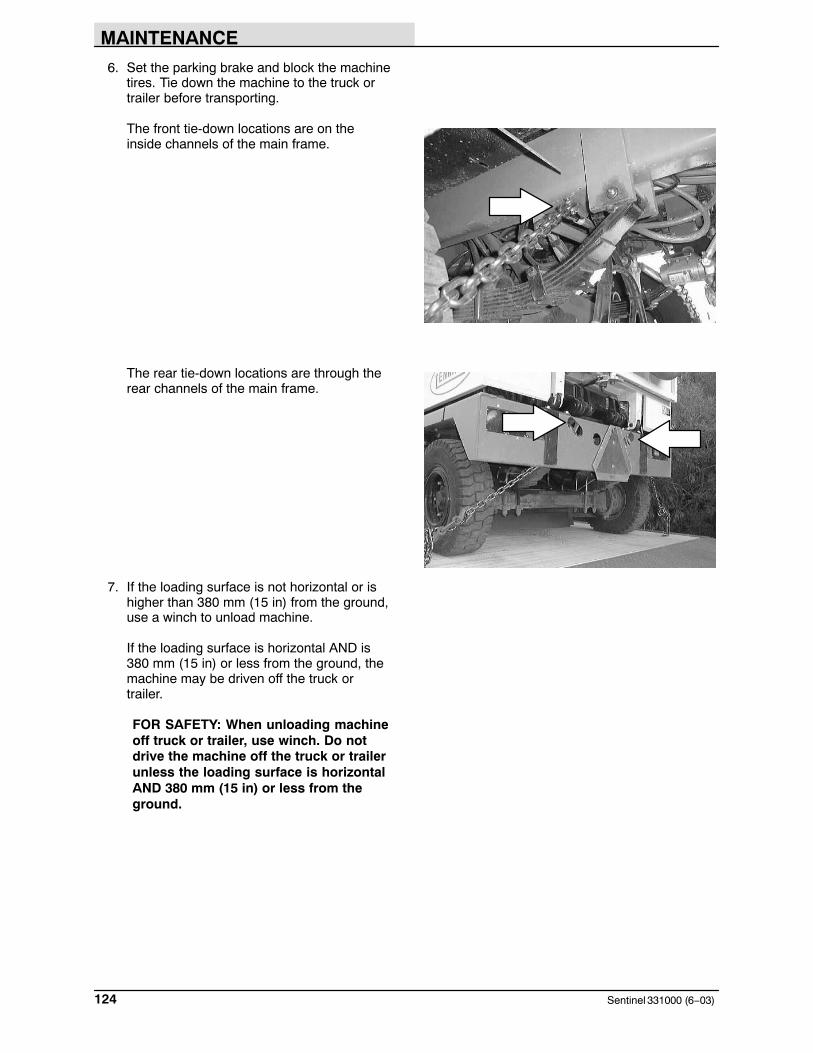
MAINTENANCE
Sentinel 331000 (6−03)124
6. Set the parking brake and block the machinetires. Tie down the machine to the truck ortrailer before transporting.
The front tie-down locations are on theinside channels of the main frame.
The rear tie-down locations are through therear channels of the main frame.
7. If the loading surface is not horizontal or ishigher than 380 mm (15 in) from the ground,use a winch to unload machine.
If the loading surface is horizontal AND is380 mm (15 in) or less from the ground, themachine may be driven off the truck ortrailer.
FOR SAFETY: When unloading machineoff truck or trailer, use winch. Do notdrive the machine off the truck or trailerunless the loading surface is horizontalAND 380 mm (15 in) or less from theground.

MAINTENANCE
125Sentinel 331000 (6−03)
MACHINE JACKING
You can jack up the machine for service at thedesignated locations. Use a Hoist or jack that willsupport the weight of the machine; a 4-ton jack forempty hopper, and a 6-ton jack with full hopper. Itis best to empty the hopper and water tank beforejacking the machine.
Always stop the machine on a flat, level surfaceand block the tires before jacking up the machine.
The front jacking locations are the front axle.
The rear jacking locations are the rear axle.
FOR SAFETY: When servicing machine,block machine tires before jackingmachine up.
FOR SAFETY: When servicing machine,jack machine up at designated locationsonly. Block machine up with jackstands.
351930
351930

MAINTENANCE
Sentinel 331000 (3−2015)126
STORING MACHINE
Before storing the machine for an extended periodof time, the machine needs to be prepped tolessen the chance of rust, sludge, and otherundesirable deposits from forming. ContactTENNANT service personnel.
1. Cover the engine air intake.
2. Cover the engine exhaust.
3. Disconnect the battery.
4. Fill the fuel tank and add a fuel stabilizationproduct.
NOTE: A cover storage kit is avaiable to provicean easy way to cover the machine.
FREEZE PROTECTION FOR WET DUSTCONTROL SYSTEM
1. Open the water valve knobs on the dashpanel to drain the lines.
2. Drain the water tank with the drain valvelocated under the tank.
3. Drain the water lines and pump by openingthe drain valve at the water pump under thecab.
4. Remove the water filter cap, located next tothe water pump, and empty it.
5. Leave the valves open if the machine is tobe stored, or not used for an extendedperiod.
FREEZE PROTECTION FOR THE HIGHPRESSURE WASHER OPTION
1. Flush the pump with a 50/50 mixture ofantifreeze and water before winter storage.
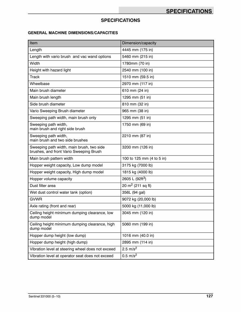
SPECIFICATIONS
127Sentinel 331000 (5−10)
SPECIFICATIONS
GENERAL MACHINE DIMENSIONS/CAPACITIES
Item Dimension/capacity
Length 4445 mm (175 in)
Length with vario brush and vac wand options 5460 mm (215 in)
Width 1780mm (70 in)
Height with hazard light 2540 mm (100 in)
Track 1510 mm (59.5 in)
Wheelbase 2970 mm (117 in)
Main brush diameter 610 mm (24 in)
Main brush length 1295 mm (51 in)
Side brush diameter 810 mm (32 in)
Vario Sweeping Brush diameter 965 mm (38 in)
Sweeping path width, main brush only 1295 mm (51 in)
Sweeping path width, main brush and right side brush
1750 mm (69 in)
Sweeping path width, main brush and two side brushes
2210 mm (87 in)
Sweeping path width, main brush, two sidebrushes, and front Vario Sweeping Brush
3200 mm (126 in)
Main brush pattern width 100 to 125 mm (4 to 5 in)
Hopper weight capacity, Low dump model 3175 kg (7000 lb)
Hopper weight capacity, High dump model 1815 kg (4000 lb)
Hopper volume capacity 2605 L (92ft3)
Dust filter area 20 m2 (211 sq ft)
Wet dust control water tank (option) 356L (94 gal)
GVWR 9072 kg (20,000 lb)
Axle rating (front and rear) 5000 kg (11,000 lb)
Ceiling height minimum dumping clearance, lowdump model
3045 mm (120 in)
Ceiling height minimum dumping clearance, highdump model
5060 mm (199 in)
Hopper dump height (low dump) 1016 mm (40.0 in)
Hopper dump height (high dump) 2895 mm (114 in)
Vibration level at steering wheel does not exceed 2.5 m/s2
Vibration level at operator seat does not exceed 0.5 m/s2

SPECIFICATIONS
Sentinel 331000 (11−2016)128
GENERAL MACHINE PERFORMANCE
Item Measure
Maximum forward speed 40.2 kmh (25 mph)
Maximum reverse speed 19.3 kmh (12 mph)
Minimum steering diameter 7.92 m (26 ft)
Minimum turning radius 3.96 m (13 ft)
Maximum rated climb and descent angle 11� (20%)
HYDRAULIC SYSTEM
System Capacity Fluid Type
Hydraulic reservoir 68.2 L (18 gal) ISO Grade 32 − below 7� C (45� F)ISO Grade 68 (Synthetic) − all temperaturesHydraulic total 121 L (32 gal)
POWER TYPE (S/N 000000−008499)
Engine Type Ignition Cycle Aspiration Cylinders Bore Stroke
CAT 3054C Piston Diesel 4 Natural(Turbo)
4 105 mm(4.13 in)
127 mm(5.00 in)
Displacement Tennant goverend power Gross intermittentpower per SAE J1995
4.41 L (269 cu in) −(Naturally aspirated)
56 kw (75 hp) @ 2200 rpm(Naturally aspirated)
60 kw (83 hp) @ 2400rpm (Naturallyaspirated)
4.41 L (269 cu in) −(Turbo)
89 kw (119 hp) @ 2200 rpm −(Turbo)
95 kw (127 hp) @2400 rpm − (Turbo)
Fuel Cooling system Electrical system
DieselFuel tank: 90.9 L (24 gal)
Water/ethylene glycol antifreeze w/conditioner
12 V nominal
Total capacity: Naturallyaspirated 17.8 L (4.7 gal)Turbo 15.52 L (4.1 gal)
130 A alternator
Radiatorcapacity: 5.68 L (1.5 gal)
12V Battery − 1000 cca
Idle speed, no load Governed speed, no load
850−900 rpm Naturally aspirated 2450−2500 rpmTurbo 2250−2350 rpm
Engine lubricating oil with filter
Naturally aspirated and Turbo:7.9 L (8.3 qt) w/o filter 10.9 L (11.5 qt) w/filter,
Naturally aspirated: API diesel classification CG4 or betterTurbo: API diesel classification CG4 or better
Air conditioner
Refrigerant R134a − total system capacity, 1.9 kg (4 lb)
PAG − Refrigerant oil, 59.148 ml (2 oz.)

SPECIFICATIONS
129Sentinel 331000 (11−2016)
POWER TYPE (S/N 008500− )
Engine Type Ignition Cycle Aspiration Cylinders Bore Stroke
CAT C4.4L Piston Diesel 4 Turbo 4 105 mm(4.13 in)
127 mm(5.00 in)
Displacement Tennant goverend power Gross intermittentpower per SAE J1995
4.4 L (269 cu in) −(Turbo)
73.1 kw (98 hp) @ 1800 rpm −(Turbo)
74.9 kw (100.4 hp) @2200 rpm − (Turbo)
Fuel Cooling system Electrical system
DieselFuel tank: 90.9 L (24 gal)
Water/ethylene glycol antifreeze w/conditioner
12 V nominal
Totalcapacity: Turbo 15.52 L (4.1 gal)
120 A alternator
Radiatorcapacity: 5.68 L (1.5 gal)
12V Battery − 1000 cca
Idle speed, no load Governed speed, no load
850−900 rpm Turbo 2250−2350 rpm
Engine lubricating oil with filter
Turbo:7.9 L (8.3 qt) w/o filter 10.9 L (11.5 qt) w/filter,
Turbo: API diesel classification CH4 or better
Air conditioner
Refrigerant R134a − total system capacity, 1.9 kg (4 lb)
PAG − Refrigerant oil, 59.148 ml (2 oz.)
STEERING
Type Power sourceFront and rear wheels, hydraulic cylinder, steeringrod, and rotary valve controlled
Hydraulic accessory pump
BRAKING SYSTEM
Type Fluid OperationService brakes Universal tractor fluid (Mobil 424) Hydraulic activated wet multi−disc
on all four wheels
Parking brake None Spring activated dry multi−disc onfront axle
TIRES
Location Type Size Ply Rating Pressure
Front and Rear (4) Bias Ply Pneumatic 7 x 12 in 16 930−1000 kPa (135−145 psi)
Front and Rear (4) Radial Pneumatic 7 x 12 in 16 930−1000 kPa (135−145 psi)

SPECIFICATIONS
Sentinel 331000 (6−03)130
5060 mm(199 in)
2540 mm(100 in)
2210 mm(87 in)
1750 mm(69 in)
Retracted1780 mm (70 in)
Extended3025 mm (119 in)
To Step1780 mm
(70 in)
2920 mm (115 in)
4440 mm (175 in)
5450 mm (215 in) Vac Wand To Aux. Brush
5230 mm (206 in)
SIDE VIEW
BOTTOM VIEW
1510 mm(59.5 in)
351930
MACHINE DIMENSIONS

INDEX
131Sentinel 331000 (5−10)
Numbers
4 way warning lights switch, 43
A
Accessory power socket, 21
Air circulation vents, 28
Air conditioner knob, 28
Air conditioning, Condensor, 101
Air filter, 102Dust cap, 102Element, 102Safety element, 102
Air intake screen, 103
Alarm, Conveyor overload, 58
Axle leaf springs, Lubrication, 92
B
Bar, Hopper support, 48
Battery, 106Voltmeter, Light, 35
Belt, Seat, 17
Belts, 107Air conditioner belt, 107Engine alternator/fan belt, 107
Blades, Windshield wiper, 106
Brackets, Conveyor stop, 55
Brake, Low brake pressure light, 29
Brake pedal, 21
Brakes, 50, 67, 119Parking, Adjustment, 119Parking brake switch, 30Service, 119System specifications, 128
Bright headlights light, 25
Brushes, 54–55, 111–116Checking main brush pattern, 114Checking side brush pattern, 115Door latch, 45Door skirts, 116Main brush, 111–115Main brush bristle length, 111Maintenance, 50, 67Pattern adjustment, 50, 67Rear skirt, 116Replacing main brush, 111–114Replacing side brush, 115Side brush, 115Side brush bristle length, 115
C
Cab, Filters, 105
Cab Jack, Operation, 82–84
Capacities, 126
CapsEngine air filter, 102Hydraulic filler, 97
CD player, 45
Chain, Conveyor, 95
Chains, 107Conveyor, 110Static drag, 107
Charging system, voltmeter, 35
Chart, Maintenance, 89–91
Cigarett, lighter, 21
Clogged engine air filter, 26
Condensor, Air conditioning, 101
Controls, 12–144 way warning lights switch, 43Accessory power socket, 21Air circulation vents, 28Air conditioner knob, 28Brake pedal, 21Bright headlights light, 25Conveyor reverse switch, 41, 58Directional lever, 21Dome and map light switch, 45Engine oil pressure gauge, 34Engine shutdown override switch, 30Engine water temperature gauge, 34Fan knob, 28Filter shaker switch, 40Front night sweeping light switch, 44Fuel level gauge, 34Fuse, 33Hazard light switch, 43Headlights switch, 19Heater knob, 27High pressure washer switch, 44Hopper door close switch, 39Hopper door open switch, 39Hopper lift switch, 38Hopper lower switch, 38Hopper overload light, 27Hopper tilt back switch, 37Hopper tilt forward switch, 37Horn, 19Hourmeter, 35Ignition switch, 20Incline light, 29Latches, 45Left side brush switch, 40Left side brush water valve knob, 31Low brake pressure light, 29

INDEX
Sentinel 331000 (5−10)132
Odometer, 35Operation, 17Parking brake light, 25Parking brake switch, 30Parking, headlights, signal lights, and horn
switch, 19Propelling pedal, 20Radio and CD player, 45Rear night sweeping light switch, 44Right side brush switch, 40Right side brush water valve knob, 32Seat belt, 17Side brush spot light(s) switch, 43Signal light, 25Speedometer, 35Steering wheel, 18Steering wheel tilt lever (For machines serial
number 007053 and below), 18Steering wheel tilt lever (For machines serial
number 007054 and above), 18Sweep switch, 42Switch panel, 37Symbols, 10–12Tachometer, 36Throttle lever, 22Traffic advisor signal light, 46Traffic advisor signal light function knob, 46Vacuum fan switch, 41Vacuum wand door light, 27Vairo sweeping brush lock pin, 22Vario sweeping brush joystick, 23Vario sweeping brush left water valve knob, 31Vario sweeping brush on−off switch, 24Vario sweeping brush raise−lower switch, 24Vario sweeping brush right water valve knob, 32Vario sweeping brush tilt/arm switch, 22Voltmeter, 35Water pump switch, 39Water tank low light, 26Windshield wiper and washer switch, 19
Conveyor, 110Bearings, Lubrication, 94Chain, Lubrication, 95Chains, 110Cleaning, 110Overload alarm, 58Paddles, 110Seals, 118Skirts, 110, 117
Conveyor overload alarm, 58
Conveyor reverse switch, 41, 58
Conveyor stop brackets, 55
Cylinder, Steering , Lubrication, 93
D
Debris, Conveyor reverse switch, 58
Debris hopper, 108–110
Differential, Lubrication, 96
Dimensions, 126
Dimensions, Machine, 129
Directional lever, 21
Disengaging hopper support bar, 73–75
Disengaging hopper support pin, 70–71
Dome and map light switch, 45
DoorsBrush
Latch, 45Skirts, 116
Cab, Latch, 45Seals, 117Side, Latch, 45
Dry dust control (option), Skirts, 116
Dust Control, WetLeft side water valve, 31Right side water valve, 32
Dust control, WetFilter, 105Operation, 77–79Pump switch, 39
Dust filter, 108Changing, 108–110Cleaning, 108–110
E
ElectricalBattery, 106Fuse, 33Ignition switch, 20
Emptying the hopper, 61–63
Engaging hopper support bar, 71–73
Engaging hopper support pin, 68–70
Engine, 101Air conditioner belt, 107Air filter, 50, 67, 102Air filter dust cap, 102Air filter element, 102Air filter intake screen, 103Alternator/fan belt, 107Clogged air filter light, 26Coolant level, 50, 67Cooling system, 101Engine shutdown override switch, 30engine valve, 104Fuel filter, 103
INDEX
133Sentinel 331000 (5−10)
Fuel level, 50, 67Fuel lines, 104Fuel water separator, 103Lubrication, 95Oil, 95Oil capacity, 95Oil level, 50, 67Oil pressure gauge, Light, 34Specifications, 127, 128Tachometer, 36Water temperature gauge, Gauge, 34
Engine oil pressure gauge, 34
Engine shutdown override switch, 30
Engine water temperature gauge, 34
F
Fan knob, 28
Filter, Clogged engine air, 26
Filter shaker switch, 40
FiltersCab, 105Hydraulic, 97Reservoir, hydraulic, 98Wet dust control, 105
Freeze protectionpressure washer, 125Wet dust control, 125
Front night sweeping light switch, 44
Fuel, Level gauge, 34
Fuel filter, 103
Fuel level gauge, 34
Fuel lines, 104
Fuel system, Fuel lines, 104
Fuel water separator, 103
Fuse, 33
G
GaugesEngine oil pressure, 34Engine water temperature, 34Fuel level, 34Hourmeter, 35Hydraulic filter, 98Odometer, 35Speedometer, 35Tachometer, 36Voltmeter, 35
Glow plugs light, 26
GVWR, 8, 54, 126
H
Hazard light switch, 43
Heater knob, 27
High pressure washer switch, 44
Hopper, 108–110Changing dust filter, 108–110Cleaning dust filter, 108–110Disengaging hopper support bar, 73–75Disengaging hopper support pin, 70–71Door close switch, 39Door open switch, 39Dust filter, 108Engaging hopper support bar, 71–73Engaging hopper support pin, 68–70Filter cleaning, 108Filter shaker switch, 40Incline light, 29Lift switch, 38Lower switch, 38Overload light, 27Seals, 118Support bar, 48Support pin, 47Thermo-Sentry, 109Tilt back switch, 37Tilt forward switch, 37
Hopper door close switch, 39
Hopper door open switch, 39
Hopper lift switch, 38
Hopper lift/tilt (high dump), Lubrication, 92
Hopper lower switch, 38
Hopper overload light, 27
Hopper support bar, 48
Hopper support pin, 47
Hopper Tilt, Lubrication, 92
Hopper tilt back switch, 37
Hopper tilt forward switch, 37
Horn, 19
Hoses, Hydraulic, 100
Hourmeter, 35
How the machine works, 49
Hydraulic cooler, Fins, 50, 67
Hydraulic fluid, 99
Hydraulic fluid reservoir, 97
Hydraulic fluid reservoir filter, 98
Hydraulic fluid reservoir filter gauge, 98
Hydraulic hoses, 100

INDEX
Sentinel 331000 (5−10)134
Hydraulics, 97–99Cooler, 101Filler cap, 97Filters, 97Fluid, 99Fluid filter guage, 98Fluid level, 50, 67, 97Hoses, 100Purging air from the hydraulic lift system, 100Reservoir, 97Reservoir filter, 98System specifications, 127
I
Ignition switch, 20
Incline light, 29, 74
Inclines, Operating on, 74
J
Jack points, 124
Joystick, 8
Joystick, Vario sweeping brush, 23
K
KnobsAir conditioner, 28Fan, 28Heater, 27Left side brush water valve, 31Right side brush water valve, 32Vario sweeping brush left water valve, 31Vario sweeping brush right water valve, 32
L
Latches, 45Cab doors, 45Main brush doors, 45Side doors, 45
Left side brush switch, 40
LeversDirectional, 21Steering wheel tilt (For machines serial number
007053 and below), 18Steering wheel tilt (For machines serial number
007054 and above), 18Throttle, 22
Lighter, cigarett, 21
Lights4 way warning lights, 43Bright headlights light, 25Clogged engine air filter, 26Dome and map light switch, 45Front night sweeping light switch, 44Glow plugs, 26Hazard light switch, 43Headlights, 19Hopper overload, 27Incline, 29Low brake pressure, 29Parking, 19Parking brake light, 25Rear night sweeping light switch, 44Side brush spot light(s) switch, 43Signal, 25Signals, 19Traffic advisor signal, 46Vacuum wand door, 27Water tank low, 26
Lock pin, Vairo sweeping brush, 22
Low brake pressure light, 29
Lubrication, 91Axle leaf springs, 92Conveyor bearings, 94Conveyor chain, 95Differential, 96Engine, 95Hopper tilt, 92Hopper lift/tilt (high dump), 92Main brush support rods, 96Side brush pivot, 93Steering cylinder, 93Vario sweeping brush, 94Wheel pivots points, 93
M
Machine components, 9
Machine dimensions, 129
Machine jacking, 124
Machine tie down location, 123
Machine troubleshooting, 86, 87
Main brush, 54, 111–115Bristle length, 111Checking brush pattern, 114Door latch, 45Door skirts, 116Maintenance, 111Replacing, 111–114Support rods, 96
INDEX
135Sentinel 331000 (5−10)
Maintenance, 88Intervals, 89–91Recommended, 8
Maintenance chart, 89–91
O
Odometer, 35
Oil pressure gauge, engine, 34
Operation, 8–60
Operation on inclines, 74
Operator Responsibility, 8
Operator seat, 17Seat belt, 17
OptionsAir conditioner belt, 107Air conditioner knob, 28Cab Jack, Operation, 82–84Dry dust control skirts, 116Front night sweeping light switch, 44High pressure washer switch, 44Hopper incline light, 29Hopper lift switch, 38Hopper lower switch, 38Left side brush switch, 40Left side brush water valve knob, 31Operation, 75–81Radio and CD player, 45Rear night sweeping light switch, 44Right side brush switch, 40Right side brush water valve knob, 32Tilting the Cab (Manually), Operation, 84–86Vacuum wand, Operation, 79–81Vacuum wand door light, 27Vairo sweeping brush lock pin, 22Vario sweeping brush, 94
Operation, 75–77Vario sweeping brush joystick, 23Vario sweeping brush left water valve knob, 31Vario sweeping brush on−off switch, 24Vario sweeping brush raise−lower switch, 24Vario sweeping brush right water valve knob, 32Vario sweeping brush tilt/arm switch, 22Water pump switch, 39Water tank low light, 26Wet dust control, Filter, 105Wet dust control system, Operation, 77–79
P
Parking brake, 119Light, 25
Parking brake light, 25
Parking brake switch, 30
Parking lights, headlights, signal, and horn switch,19
Pedal, Propelling, 20
Pedals, Brake, 21
Pin, Hopper support pin, 47
Post-operation checklist, 67
Pre-operation checklist, 50–53
Preheat, Glow plugs, 26
Propelling pedal, 20
Purging air from the hydraulic conveyor liftsystem, 100
Pushing machine, 121
Pushing or towing the machine, 121
Pushing, towing, and transporting machine, 121
R
RadiatorCoolant level, 101Coolant type, 101Exterior, 101Fins, 50, 67Flushing system, 101Hoses, 101
Radio, 45
Radio and CD player, 45
Re−phasing the conveyor lift system, 100
Rear night sweeping light switch, 44
Reservoir, hydraulic, 97
Right side brush switch, 40
S
Safety4 way warning lights switch, 43Disengaging hopper support bar, 73–75Disengaging hopper support pin, 70–71Engaging hopper support bar, 71–73Engaging hopper support pin, 68–70Hopper support bar, 48Hopper support pin, 47Labels, 6Precautions, 4Vario sweeping brush lock pin, 22

INDEX
Sentinel 331000 (5−10)136
Safety element, 102
Seals, 116–118Conveyor, 118Door, 117Hopper, 118
Seat, 17Adjustment, 17
Seat Belt, 17
Separator, Fuel water, 103
Service records, 50, 67
Side brush, 54, 115Bristle length, 115Checking brush pattern, 115Replacing, 115Vario, Lubrication, 94
Side brush pivot, Lubrication, 93
Side brush spot light(s) switch, 43
Side brush switch, left, 40
Side brush switch, right, 40
Signal light, 25
Skids, 119
Skirts, 116Brush compartment, 116Brush doors, 116Conveyor, 117Dry dust control (option), 116
Skirts and seals, 50, 67
Specifications, 126–127Braking system, 128GVWR, 126Hydraulic system, 127Machine capacities, 126Machine dimensions, 126Machine performance, 127Power type, 127, 128Steering, 128Tires, 128
Speedometer, 35
Starting the machine, 51–53
Static drag chain, 107
Steering, 50, 67Specifications, 128
Steering cylinder, Lubrication, 93
Steering wheel, 18
Steering wheel tilt lever (For machines serialnumber 007053 and below), 18
Steering wheel tilt lever (For machines serialnumber 007054 and above), 18
Stop sweeping, 59
Stop the machine, 65–67
Storing machine, 125Freeze protection, 125
Sweep switch, 42
Sweeping, 55–58
Sweeping and brush information, 54–55
Switch PanelConveyor reverse switch, 41Filter shaker switch, 40Hopper door close switch, 39Hopper door open switch, 39Hopper lift switch, 38Hopper lower switch, 38Hopper tilt back switch, 37Hopper tilt forward switch, 37Left side brush switch, 40Right side brush switch, 40Sweep switch, 42Vacuum fan switch, 41Water pump switch, 39
Switch panel, 37
Switches4 way warning lights, 43Conveyor reverse, 41, 58Dome and map light, 45Engine shutdown override switch, 30Filter shaker, 40Front night sweeping light, 44Hazard light, 43Headlights, 19High pressure washer, 44Hopper door close switch, 39Hopper door open switch, 39Hopper lift switch, 38Hopper lower switch, 38Hopper tilt back, 37Hopper tilt forward, 37Horn, 19Ignition, 20Left side brush, 40Parking and signal lights, 19Parking brake, 30Rear night sweeping light, 44Right side brush, 40Side brush spot light(s), 43Sweep, 42Switch panel, 37Traffic advisor signal light, 46Traffic advisor signal light function, 46Vacuum fan, 41Vario sweeping brush on−off, 24Vario sweeping brush raise−lower, 24Vario sweeping brush tilt/arm , 22Water pump, 39Windshield wiper and washer, 19

INDEX
137Sentinel 331000 (5−10)
T
Tachometer, 36
Thermo-sentry, 109
Throttle, Lever, 22
Throttle lever, 22
Tie down location, 123
Tilting the Cab (Manually), Operation, 84–86
Tires, 119–121Pressure, 120Specifications, 128
Towing machine, 121
Traffic advisor signal light, 46
Traffic advisor signal light function knob, 46
Transporting machine, 121
Transporting the machine, 122
Travel speed, 127
Troubleshooting, 86, 87
Turning radius, 127
V
Vacuum fan switch, 41
Vacuum wandDoor light, 27Operation, 79–81
Vacuum wand door light, 27
Vario sweeping brushJoystick, 23Left water valve knob, 31Lock pin, 22Lubrication, 94On−off switch, 24Operation, 75–77Raise−lower switch, 24Right water valve knob, 32Tilt/arm switch, 22
Vents, Air circulation, 28
W
Washer, High pressure washer switch, 44
Water pump switch, 39
Water separator, Fuel, 103
Water tank low light, 26
Weight limit, 8, 54, 126
Wet dust control filter, Filter, 105
Wet dust control system, Operation, 77–79
Wheel alignment, 120
Wheel nuts, 120Torque, 120
Wheel pivots, Lubrication points, 93
WheelsAlignment, 120Leaf springs, Lubrication, 92Nuts, 120Pivots points, Lubrication, 93
Windshield washer, 106
Windshield washer and wiper switch, 19
Windshield washer fluid level, 50
Windshield wiper, Blades, 106
Windshield wipers, Switch, 19