Sensors Porting Guide
18
Qualcomm Technologies, Inc. © 2015 Qualcomm Technologies, Inc. All rights reserved. Qualcomm Snapdragon is a product of Qualcomm Technologies, Inc. Other Qualcomm products referenced herein are products of Qualcomm Technologies, Inc. or its other subsidiaries. DragonBoard, Qualcomm and Snapdragon are trademarks of Qualcomm Incorporated, registered in the United States and other countries. All Qualcomm Incorporated trademarks are used with permission. Other product and brand names may be trademarks or registered trademarks of their respective owners. This technical data may be subject to U.S. and international export, re-export, or transfer (“export”) laws. Diversion contrary to U.S. and international law is strictly prohibited. Use of this document is subject to the license set forth in Exhibit 1. Questions or comments: https://www.96boards.org/DragonBoard410c/forum Qualcomm Technologies, Inc. 5775 Morehouse Drive San Diego, CA 92121 U.S.A. LM80-P0436-9 Rev C DragonBoard™ 410c based on Qualcomm ® Snapdragon™ 410 processor Sensors Porting Guide LM80-P0436-9 Rev C June 2015
-
Upload
vuongkhanh -
Category
Documents
-
view
244 -
download
1
Transcript of Sensors Porting Guide
Qualcomm Technologies, Inc.
© 2015 Qualcomm Technologies, Inc. All rights reserved.
Qualcomm Snapdragon is a product of Qualcomm Technologies, Inc. Other Qualcomm products referenced herein are products of Qualcomm Technologies, Inc. or its other subsidiaries.
DragonBoard, Qualcomm and Snapdragon are trademarks of Qualcomm Incorporated, registered in the United States and other countries. All Qualcomm Incorporated trademarks are used with permission. Other product and brand names may be trademarks or registered trademarks of their respective owners.
This technical data may be subject to U.S. and international export, re-export, or transfer (“export”) laws. Diversion contrary to U.S. and international law is strictly prohibited.
Use of this document is subject to the license set forth in Exhibit 1.
Questions or comments: https://www.96boards.org/DragonBoard410c/forum
Qualcomm Technologies, Inc. 5775 Morehouse Drive San Diego, CA 92121
U.S.A.
LM80-P0436-9 Rev C
DragonBoard™ 410c based on Qualcomm® Snapdragon™ 410 processor
Sensors Porting Guide
LM80-P0436-9 Rev C
June 2015
LM80-P0436-9 Rev C MAY CONTAIN U.S. AND INTERNATIONAL EXPORT CONTROLLED INFORMATION 2
Revision history
Revision Date Description
C June 12, 2015 Miscellaneous updates.
B May 22, 2015 Updated Revision history and © date for Rev B.
A May 6, 2015 Initial release
LM80-P0436-9 Rev C MAY CONTAIN U.S. AND INTERNATIONAL EXPORT CONTROLLED INFORMATION 3
Contents
1 Introduction ........................................................................................................................... 4
1.1 Purpose ..................................................................................................................................................... 4 1.2 Scope ......................................................................................................................................................... 4 1.3 Conventions ............................................................................................................................................... 4 1.4 Additional information ................................................................................................................................ 4
2 Native Sensors Framework .................................................................................................. 5
2.1 Background ................................................................................................................................................ 5
3 Sensor Drivers ...................................................................................................................... 6
3.1 Regulator configurations ............................................................................................................................ 6 3.1.1 Device tree configurations ........................................................................................................ 6 3.1.2 Regulator initializations ............................................................................................................. 7
3.2 Pinctrl configurations .................................................................................................................................. 7 3.2.1 Device tree configurations ........................................................................................................ 7 3.2.2 Pinctrl initializations .................................................................................................................. 8
3.3 Sensor class support ................................................................................................................................. 8 3.4 Other issues ............................................................................................................................................... 9
4 Native Sensors HAL .............................................................................................................10
4.1 CalibrationManager .................................................................................................................................. 10 4.1.1 Data structure ........................................................................................................................ 11 4.1.2 Calibration library .................................................................................................................... 13
4.2 NativeSensorManager ............................................................................................................................. 14 4.2.1 NativeSensorManager initialization ......................................................................................... 15 4.2.2 Command flow and data flow management ............................................................................ 15 4.2.3 Virtual sensor management .................................................................................................... 16
4.3 Virtual sensors ......................................................................................................................................... 16 4.3.1 Virtual sensor implementation in HAL ..................................................................................... 16 4.3.2 How does the virtual sensor work? .......................................................................................... 17 4.3.3 Add customized virtual sensors .............................................................................................. 17
Figures
Figure 2-1 Sensor software architecture on Android OS ................................................................................................. 5 Figure 3-1 General design Diagram ............................................................................................................................... 8 Figure 4-1 CalibrationManager structure ...................................................................................................................... 10 Figure 4-2 Stack of sensors ......................................................................................................................................... 14
LM80-P0436-9 Rev C MAY CONTAIN U.S. AND INTERNATIONAL EXPORT CONTROLLED INFORMATION 4
1 Introduction
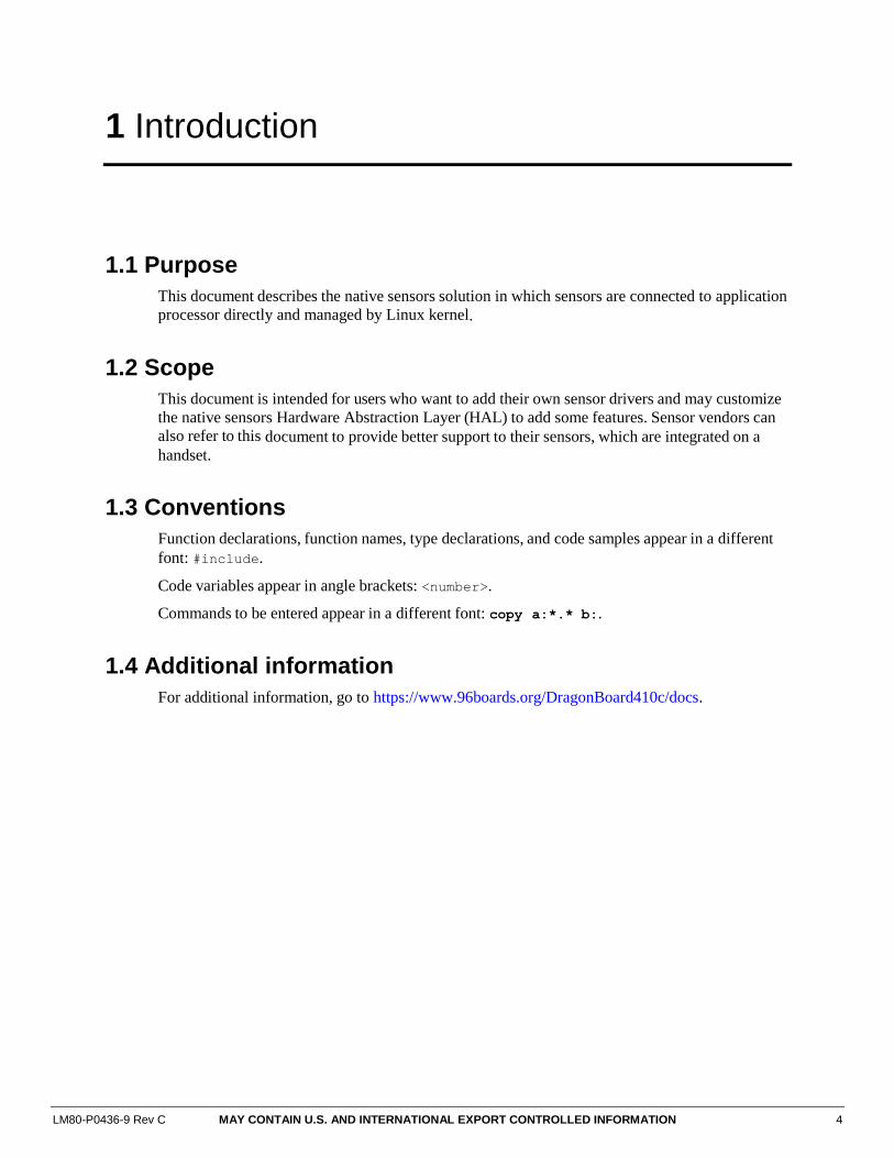
1.1 Purpose
This document describes the native sensors solution in which sensors are connected to application
processor directly and managed by Linux kernel.
1.2 Scope
This document is intended for users who want to add their own sensor drivers and may customize
the native sensors Hardware Abstraction Layer (HAL) to add some features. Sensor vendors can
also refer to this document to provide better support to their sensors, which are integrated on a
handset.
1.3 Conventions
Function declarations, function names, type declarations, and code samples appear in a different
font: #include.
Code variables appear in angle brackets: <number>.
Commands to be entered appear in a different font: copy a:*.* b:.
1.4 Additional information
For additional information, go to https://www.96boards.org/DragonBoard410c/docs.
LM80-P0436-9 Rev C MAY CONTAIN U.S. AND INTERNATIONAL EXPORT CONTROLLED INFORMATION 5
2 Native Sensors Framework
This section provides an overview of the native sensors, including the kernel drivers, native
sensors HAL, as well as the SensorService.
2.1 Background
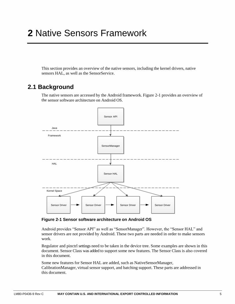
The native sensors are accessed by the Android framework. Figure 2-1 provides an overview of
the sensor software architecture on Android OS.
Sensor API
SensorManager
Sensor HAL
Sensor Driver Sensor Driver Sensor Driver Sensor Driver
Java
Framework
HAL
Kernel Space
Figure 2-1 Sensor software architecture on Android OS
Android provides “Sensor API” as well as “SensorManager”. However, the “Sensor HAL” and
sensor drivers are not provided by Android. These two parts are needed in order to make sensors
work.
Regulator and pinctrl settings need to be taken in the device tree. Some examples are shown in this
document. Sensor Class was added to support some new features. The Sensor Class is also covered
in this document.
Some new features for Sensor HAL are added, such as NativeSensorManager,
CalibrationManager, virtual sensor support, and batching support. These parts are addressed in
this document.
LM80-P0436-9 Rev C MAY CONTAIN U.S. AND INTERNATIONAL EXPORT CONTROLLED INFORMATION 6
3 Sensor Drivers
This section describes the sensor drivers in the Linux kernel, including regulator, pinctrl, and
sensor class configurations. Generally, the sensor drivers are present in drivers/input/misc/
directory in kernel source tree.
One sample driver will be refered to it in this document.
Please refer to this link for more details:
https://www.codeaurora.org/cgit/quic/la/kernel/msm-
3.10/tree/drivers/input/misc/mmc3416x.c?h=msm-3.10
3.1 Regulator configurations
Default initial sensor drivers do not have the power on/off routine for msm/apq chipsets. It is
better to add that for the sensors to correctly power on/off.
3.1.1 Device tree configurations
The power of sensor chips are initialized in a probe routine of the sensor driver. The MSM
chipsets use device trees to configure the power rail. Here is one sample to configure the
mmc3416xpj driver, which is a magnetometer sensor chip.
memsic@30 { /* Magnetic field sensor */
compatible = "memsic,mmc3416x";
reg = <0x30>;
vdd-supply = <&pm8916_l17>;
vio-supply = <&pm8916_l6>;
memsic,dir = "obverse-x-axis-forward";
memsic,auto-report;
};
The vdd-supply indicates the analog power supply needed to power-up the sensor device, while
the vio-supply indicates the digital power supply needed for IO and I2C. The pm8916_l17 and
pm8916_l6 are the regulators to use. Check the device board schematic to choose the correct
regulators for this sensor. The name of the regulator can be found in
arch/arm/boot/dts/qcom/xxxx-regulator.dtsi, the xxxx standing for the MSM chipset
you are using.
The sensor chip depends on the bus in use, such as the I2C bus and the SPI bus. The regulator of
the bus should also be voted on.
For more information about the device tree, refer to
kernel/Documentation/bindings/input/misc/.
DragonBoard™ 410c based on Qualcomm® Snapdragon™ 410 processor Sensors Porting Guide Sensor Drivers
LM80-P0436-9 Rev C MAY CONTAIN U.S. AND INTERNATIONAL EXPORT CONTROLLED INFORMATION 7
3.1.2 Regulator initializations
The regulator should be initialized before operating the sensor chip. The regulator_get,
regualator_count_voltages, regulator_set_voltages, regulator_enable, and
regulator_disable are the common regulator operation functions needed.
The regulator may also be configured during the enable/disable routine and the suspend/resume
routine to save power. The power of the sensor chip must be correctly handled to avoid power
leakage and sensor chip NACK issues.
Refer to drivers/input/misc/mmc3416x.c for details.
3.2 Pinctrl configurations
The MSM8916/APQ8016 chipset use pinctrl to manage the pin states. The sensor chips that have
a reset pin or interrupt pin must have their pins managed by pinctrl framework. The pins have an
“active” state and a “sleep” state. The drivers must configure the pin to be “active” when the
sensor chip is working. The “sleep” state must be selected if the sensors does not need to work
and enters into low power mode.
3.2.1 Device tree configurations akm@c {
compatible = "ak,ak09911";
reg = <0x0c>;
pinctrl-names = "default","sleep";
pinctrl-0 = <&akm_default>;
pinctrl-1 = <&akm_sleep>;
vdd-supply = <&pm8916_l17>;
vio-supply = <&pm8916_l6>;
akm,layout = <0x3>;
akm,gpio_rstn = <&msm_gpio 36 0x0>;
akm,auto-report;
};
akm_reset_pin {
qcom,pins = <&gp 36>;
qcom,pin-func = <0>;
qcom,num-grp-pins = <1>;
label = "akm_reset_pin";
akm_default: akm_default {
drive-strength = <6>;
bias-pull-up;
};
akm_sleep: akm_sleep {
drive-strength = <2>;
bias-pull-down;
};
};
DragonBoard™ 410c based on Qualcomm® Snapdragon™ 410 processor Sensors Porting Guide Sensor Drivers
LM80-P0436-9 Rev C MAY CONTAIN U.S. AND INTERNATIONAL EXPORT CONTROLLED INFORMATION 8
The pinctrl-names indicates the name of the pinctrl configurations for “pinctrl-0” and “pinctl-
1”. Drivers can use “default” and “sleep” to refer to the corresponding pinctrl configurations. The
akm_default and akm_sleep must be present in tlmm_pinmux device tree configurations. Refer
to arch/arm/boot/dts/qcom/msm8916-qrd-skuh.dtsi for more details.
3.2.2 Pinctrl initializations
The regulator should be initialized during the probe process during the driver initializations. The
following functions need to be called:
pinctrl_get() – retrieves the pinctrl handle for a device.
pinctrl_lookup_state() – retrieves a state handle from a pinctrl handle.
pinctrl_select_state() – select/activate/program a pinctrl state to HW.
Refer to the akm_pinctrl_init function and other pinctrl related functions in
drivers/input/misc/akm09911.c for more details.
3.3 Sensor class support
Sensor class support is part of general HAL support. Its main purpose is to make the Sensor HAL
more generic. All of the hardware related configurations are provided by kernel. To support this
feature, the kernel drivers need to follow the interfaces.
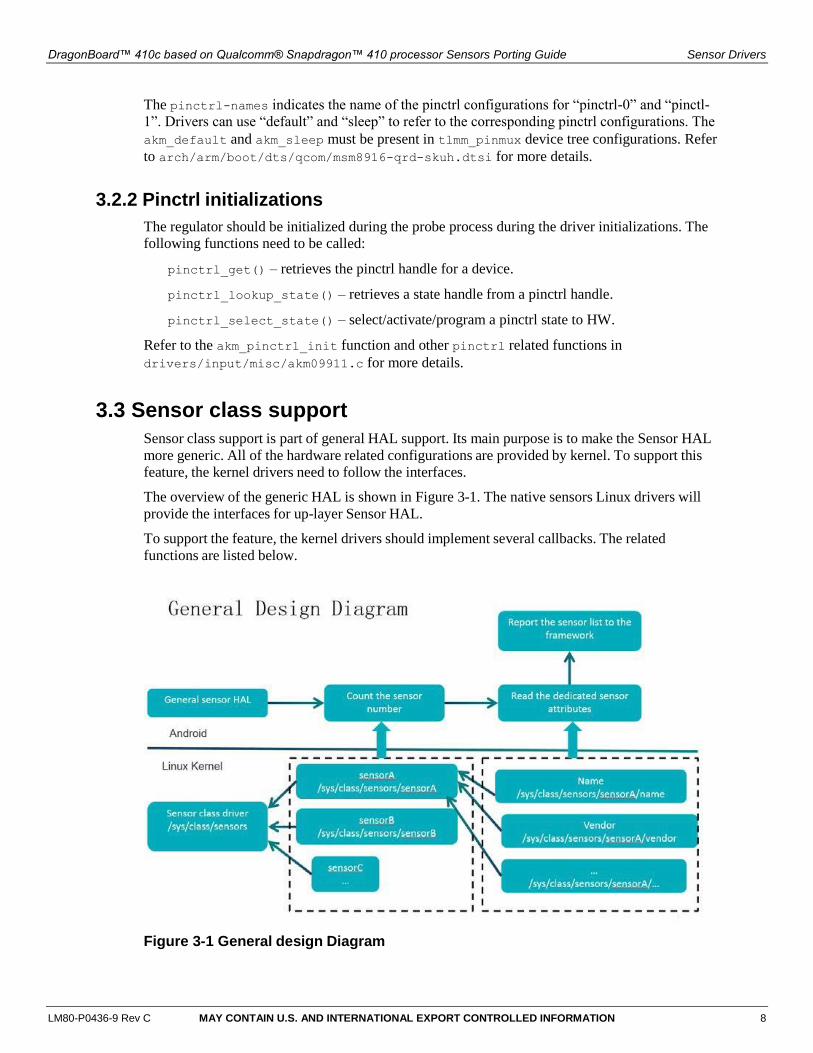
The overview of the generic HAL is shown in Figure 3-1. The native sensors Linux drivers will
provide the interfaces for up-layer Sensor HAL.
To support the feature, the kernel drivers should implement several callbacks. The related
functions are listed below.
Figure 3-1 General design Diagram
DragonBoard™ 410c based on Qualcomm® Snapdragon™ 410 processor Sensors Porting Guide Sensor Drivers
LM80-P0436-9 Rev C MAY CONTAIN U.S. AND INTERNATIONAL EXPORT CONTROLLED INFORMATION 9
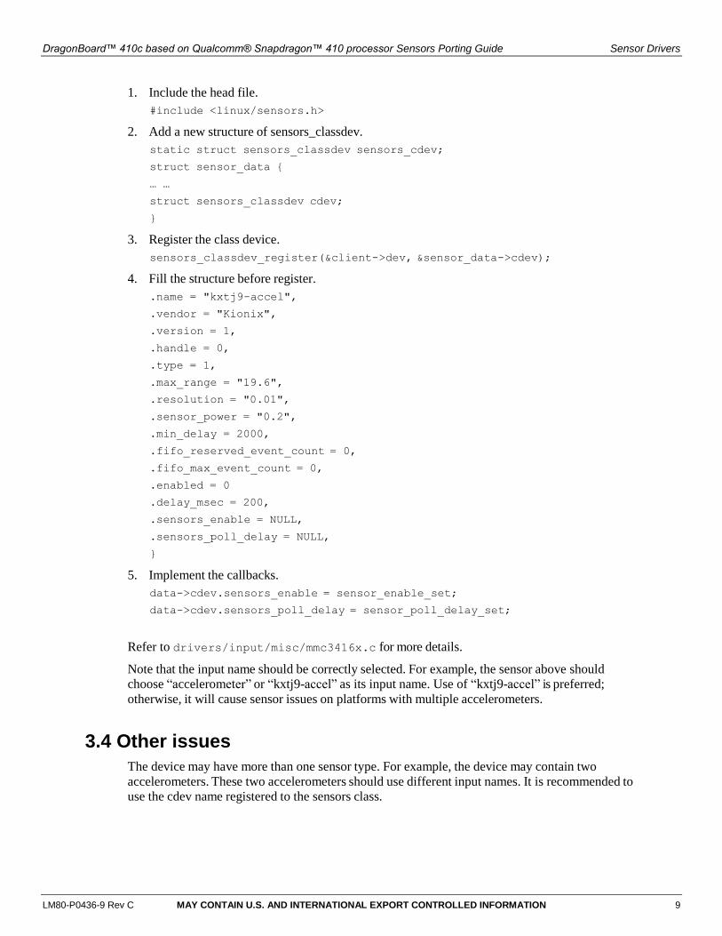
1. Include the head file.
#include <linux/sensors.h>
2. Add a new structure of sensors_classdev.
static struct sensors_classdev sensors_cdev;
struct sensor_data {
… …
struct sensors_classdev cdev;
}
3. Register the class device.
sensors_classdev_register(&client->dev, &sensor_data->cdev);
4. Fill the structure before register.
.name = "kxtj9-accel",
.vendor = "Kionix",
.version = 1,
.handle = 0,
.type = 1,
.max_range = "19.6",
.resolution = "0.01",
.sensor_power = "0.2",
.min_delay = 2000,
.fifo_reserved_event_count = 0,
.fifo_max_event_count = 0,
.enabled = 0
.delay_msec = 200,
.sensors_enable = NULL,
.sensors_poll_delay = NULL,
}
5. Implement the callbacks.
data->cdev.sensors_enable = sensor_enable_set;
data->cdev.sensors_poll_delay = sensor_poll_delay_set;
Refer to drivers/input/misc/mmc3416x.c for more details.
Note that the input name should be correctly selected. For example, the sensor above should
choose “accelerometer” or “kxtj9-accel” as its input name. Use of “kxtj9-accel” is preferred;
otherwise, it will cause sensor issues on platforms with multiple accelerometers.
3.4 Other issues
The device may have more than one sensor type. For example, the device may contain two
accelerometers. These two accelerometers should use different input names. It is recommended to
use the cdev name registered to the sensors class.
LM80-P0436-9 Rev C MAY CONTAIN U.S. AND INTERNATIONAL EXPORT CONTROLLED INFORMATION 10
4 Native Sensors HAL
The Sensor HAL connects the sensor driver and Android framework for sensors. It abstracts the
hardware and provides the callbacks provided by Android Sensor HAL interface. You can find
the definitions in hardware/libhardware/include/hardware/sensors.h.
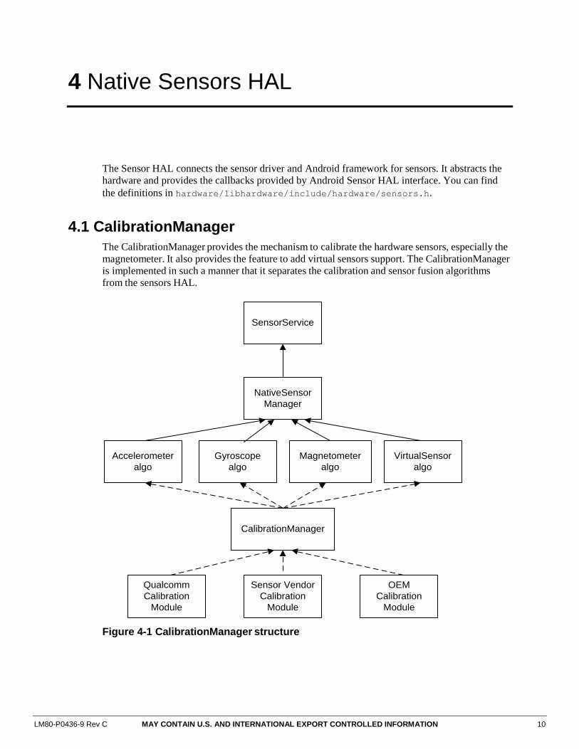
4.1 CalibrationManager
The CalibrationManager provides the mechanism to calibrate the hardware sensors, especially the
magnetometer. It also provides the feature to add virtual sensors support. The CalibrationManager
is implemented in such a manner that it separates the calibration and sensor fusion algorithms
from the sensors HAL.
SensorService
NativeSensor
Manager
VirtualSensor
algo
Magnetometer
algo
Gyroscope
algo
Accelerometer
algo
CalibrationManager
Qualcomm
Calibration
Module
Sensor Vendor
Calibration
Module
OEM
Calibration
Module
Figure 4-1 CalibrationManager structure
DragonBoard™ 410c based on Qualcomm® Snapdragon™ 410 processor Sensors Porting Guide Native Sensors HAL
LM80-P0436-9 Rev C MAY CONTAIN U.S. AND INTERNATIONAL EXPORT CONTROLLED INFORMATION 11
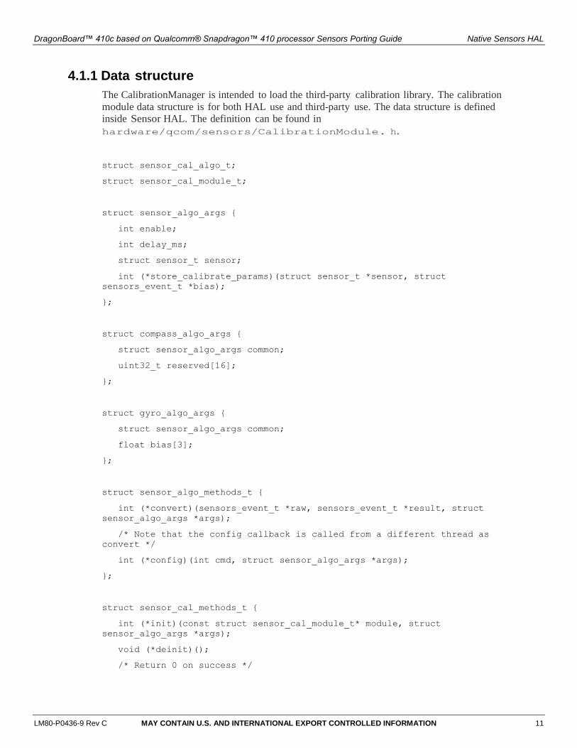
4.1.1 Data structure
The CalibrationManager is intended to load the third-party calibration library. The calibration
module data structure is for both HAL use and third-party use. The data structure is defined
inside Sensor HAL. The definition can be found in
hardware/qcom/sensors/CalibrationModule. h.
struct sensor_cal_algo_t;
struct sensor_cal_module_t;
struct sensor_algo_args {
int enable;
int delay_ms;
struct sensor_t sensor;
int (*store_calibrate_params)(struct sensor_t *sensor, struct
sensors_event_t *bias);
};
struct compass_algo_args {
struct sensor_algo_args common;
uint32_t reserved[16];
};
struct gyro_algo_args {
struct sensor_algo_args common;
float bias[3];
};
struct sensor_algo_methods_t {
int (*convert)(sensors_event_t *raw, sensors_event_t *result, struct
sensor_algo_args *args);
/* Note that the config callback is called from a different thread as
convert */
int (*config)(int cmd, struct sensor_algo_args *args);
};
struct sensor_cal_methods_t {
int (*init)(const struct sensor_cal_module_t* module, struct
sensor_algo_args *args);
void (*deinit)();
/* Return 0 on success */

DragonBoard™ 410c based on Qualcomm® Snapdragon™ 410 processor Sensors Porting Guide Native Sensors HAL
LM80-P0436-9 Rev C MAY CONTAIN U.S. AND INTERNATIONAL EXPORT CONTROLLED INFORMATION 12
int (*get_algo_list)(const struct sensor_cal_algo_t **algo);
};
struct sensor_cal_algo_t {
/* Tag of the algo */
int tag;
/* Version of the algo */
int version;
/* Type of sensor this algo supported*/
int type;
/* The compatible sensors */
const char **compatible;
/* Sensor calibration module */
struct sensor_cal_module_t *module;
/* Sensor algo methods */
struct sensor_algo_methods_t *methods;
};
struct sensor_cal_module_t {
/* Tag of the module */
uint32_t tag;
/* Id of the module */
char *id;
/* Version of the calibration module */
uint32_t version;
/* Vendor of the calibration lib */
char *vendor;
/* Point to the handle of this module */
void *dso;
/* Number of algos */
uint32_t number;
/* Callbacks of the calibration lib provided */
struct sensor_cal_methods_t *methods;
/* The compatible sensors list for this library */
int reserved[6];
};
DragonBoard™ 410c based on Qualcomm® Snapdragon™ 410 processor Sensors Porting Guide Native Sensors HAL
LM80-P0436-9 Rev C MAY CONTAIN U.S. AND INTERNATIONAL EXPORT CONTROLLED INFORMATION 13
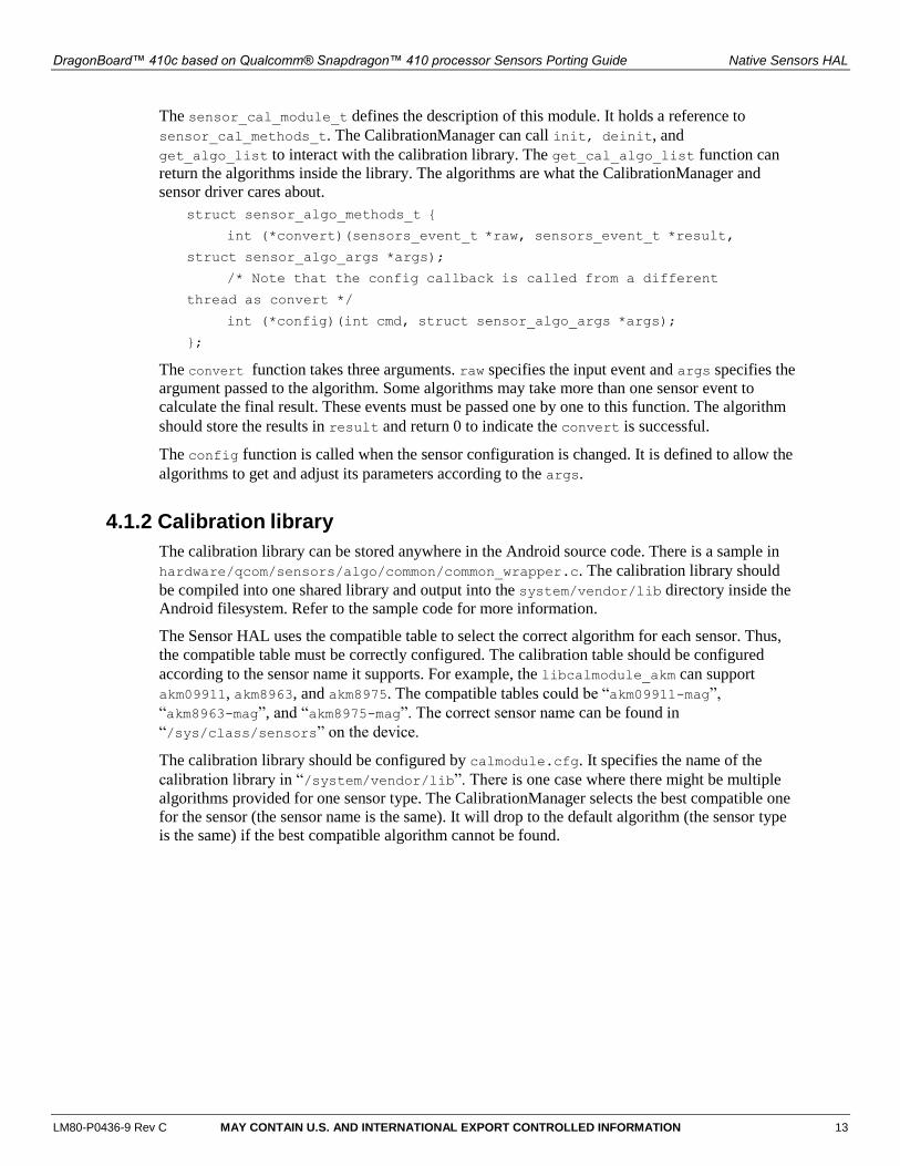
The sensor_cal_module_t defines the description of this module. It holds a reference to
sensor_cal_methods_t. The CalibrationManager can call init, deinit, and
get_algo_list to interact with the calibration library. The get_cal_algo_list function can
return the algorithms inside the library. The algorithms are what the CalibrationManager and
sensor driver cares about.
struct sensor_algo_methods_t {
int (*convert)(sensors_event_t *raw, sensors_event_t *result,
struct sensor_algo_args *args);
/* Note that the config callback is called from a different
thread as convert */
int (*config)(int cmd, struct sensor_algo_args *args);
};
The convert function takes three arguments. raw specifies the input event and args specifies the
argument passed to the algorithm. Some algorithms may take more than one sensor event to
calculate the final result. These events must be passed one by one to this function. The algorithm
should store the results in result and return 0 to indicate the convert is successful.
The config function is called when the sensor configuration is changed. It is defined to allow the
algorithms to get and adjust its parameters according to the args.
4.1.2 Calibration library
The calibration library can be stored anywhere in the Android source code. There is a sample in
hardware/qcom/sensors/algo/common/common_wrapper.c. The calibration library should
be compiled into one shared library and output into the system/vendor/lib directory inside the
Android filesystem. Refer to the sample code for more information.
The Sensor HAL uses the compatible table to select the correct algorithm for each sensor. Thus,
the compatible table must be correctly configured. The calibration table should be configured
according to the sensor name it supports. For example, the libcalmodule_akm can support
akm09911, akm8963, and akm8975. The compatible tables could be “akm09911-mag”,
“akm8963-mag”, and “akm8975-mag”. The correct sensor name can be found in
“/sys/class/sensors” on the device.
The calibration library should be configured by calmodule.cfg. It specifies the name of the
calibration library in “/system/vendor/lib”. There is one case where there might be multiple
algorithms provided for one sensor type. The CalibrationManager selects the best compatible one
for the sensor (the sensor name is the same). It will drop to the default algorithm (the sensor type
is the same) if the best compatible algorithm cannot be found.
DragonBoard™ 410c based on Qualcomm® Snapdragon™ 410 processor Sensors Porting Guide Native Sensors HAL
LM80-P0436-9 Rev C MAY CONTAIN U.S. AND INTERNATIONAL EXPORT CONTROLLED INFORMATION 14
4.2 NativeSensorManager
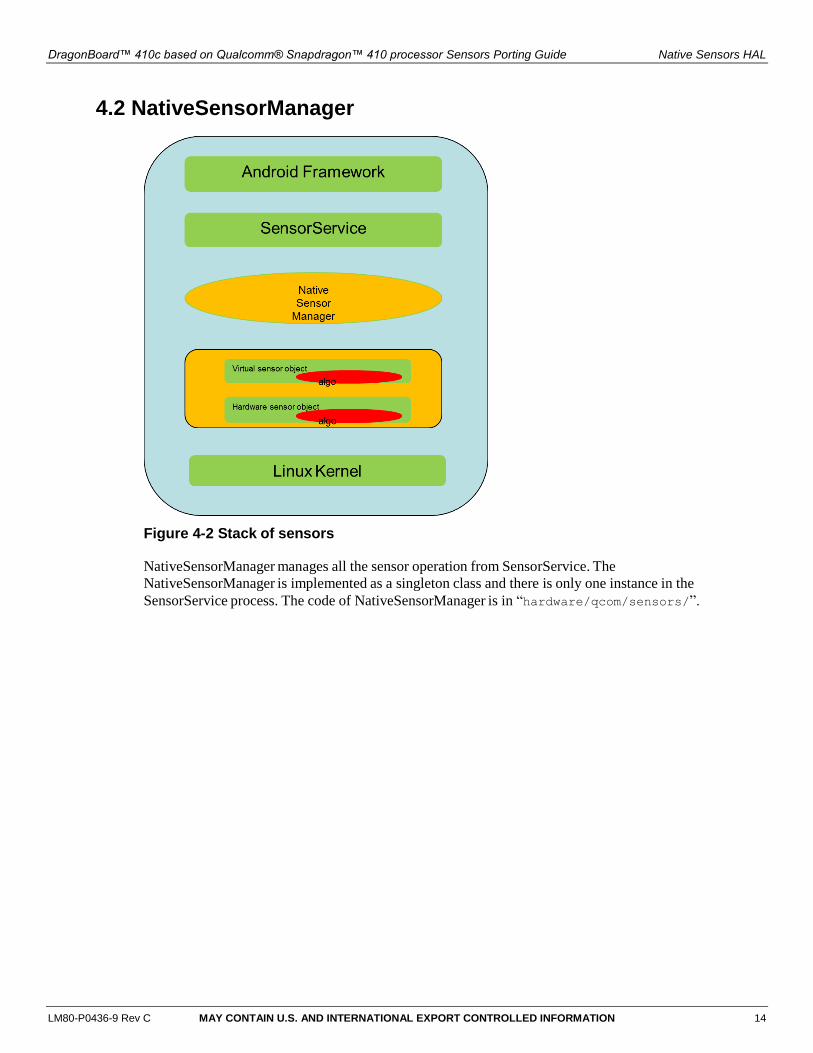
Figure 4-2 Stack of sensors
NativeSensorManager manages all the sensor operation from SensorService. The
NativeSensorManager is implemented as a singleton class and there is only one instance in the
SensorService process. The code of NativeSensorManager is in “hardware/qcom/sensors/”.
DragonBoard™ 410c based on Qualcomm® Snapdragon™ 410 processor Sensors Porting Guide Native Sensors HAL
LM80-P0436-9 Rev C MAY CONTAIN U.S. AND INTERNATIONAL EXPORT CONTROLLED INFORMATION 15
SensorServiceSensors_poll_c
otext_t
NativeSensor
ManagerSensorBase
activateactivate
activate
enable
Activate/Deactivate the
listeners/dependency
Read events from
sensor driver and inject
the sensor events to
listeners
readEvents
readEventspollEventspoll
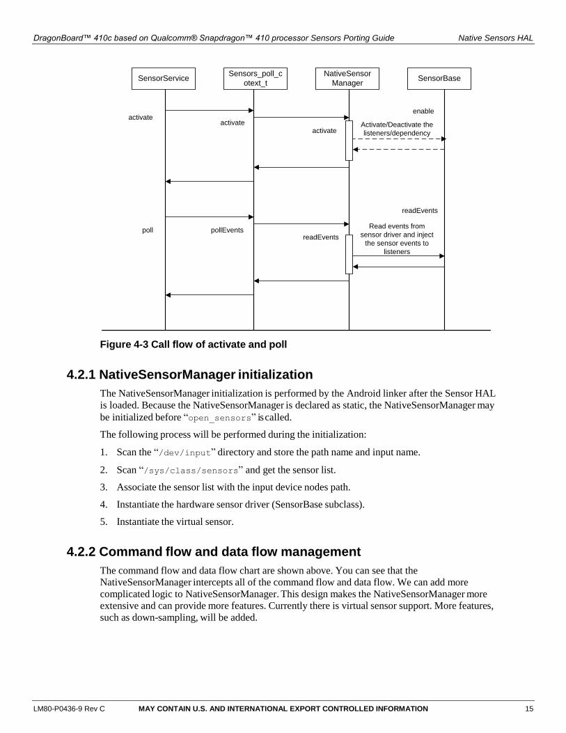
Figure 4-3 Call flow of activate and poll
4.2.1 NativeSensorManager initialization
The NativeSensorManager initialization is performed by the Android linker after the Sensor HAL
is loaded. Because the NativeSensorManager is declared as static, the NativeSensorManager may
be initialized before “open_sensors” is called.
The following process will be performed during the initialization:
1. Scan the “/dev/input” directory and store the path name and input name.
2. Scan “/sys/class/sensors” and get the sensor list.
3. Associate the sensor list with the input device nodes path.
4. Instantiate the hardware sensor driver (SensorBase subclass).
5. Instantiate the virtual sensor.
4.2.2 Command flow and data flow management
The command flow and data flow chart are shown above. You can see that the
NativeSensorManager intercepts all of the command flow and data flow. We can add more
complicated logic to NativeSensorManager. This design makes the NativeSensorManager more
extensive and can provide more features. Currently there is virtual sensor support. More features,
such as down-sampling, will be added.
DragonBoard™ 410c based on Qualcomm® Snapdragon™ 410 processor Sensors Porting Guide Native Sensors HAL
LM80-P0436-9 Rev C MAY CONTAIN U.S. AND INTERNATIONAL EXPORT CONTROLLED INFORMATION 16
4.2.3 Virtual sensor management
The virtual sensor is managed by the NativeSensorManager. The virtual sensors supported are
Orientation, Linear Acceleration, Gravity, Rotation Vector, Pseudo Gyroscope, and Uncalibrated
Magnetic Field. However, most of the virtual sensor algorithms are provided by a third party, such
as a sensor chip vendor. Some sample algorithms were also added, but the performance is not that
good.
Currently the logic is to query the calibration library to find out the supported algorithms. The
algorithms are defined in the calibration library provided a compatible list, which is to adapt to the
sensor list in HAL. For example, the rotation vector sensor algorithm may contain “oem-rotation-
vector” in the compatible list. The NativeSensorManager will select it as the default algorithm to
calculate the rotation vector sensor data. The NativeSensorManager will also select the algorithm
with the “rotation_vector” listed in compatible list, since it is the default name of rotation vector
sensor name. The full list of default compatible sensor name can be found in
“hardware/qcom/sensors/CalibrationModule.h”.
4.3 Virtual sensors
The virtual sensors are provided by the sensor fusion algorithms. These fusion algorithms could
be provided by SoC vendors and/or sensor vendors. Android also provides a default
implementation of rotation vector, gravity, and linear acceleration if the device does not have
these implementations. However, the implementation is only available when the device has a
gyroscope, accelerometer, and magnetometer. The default implementation does not have access
to all the data that other implementations do, and must run on the SoC, so it is not as accurate nor
as power efficient as the other implementations can be. As much as possible, device manufactures
should define their own fused sensors.
4.3.1 Virtual sensor implementation in HAL
Accelerometer
. . .
Magnetometer
Rotation Vector
Rotation Vector
Gravity
Orientation
Virtual Sensor Algorithms
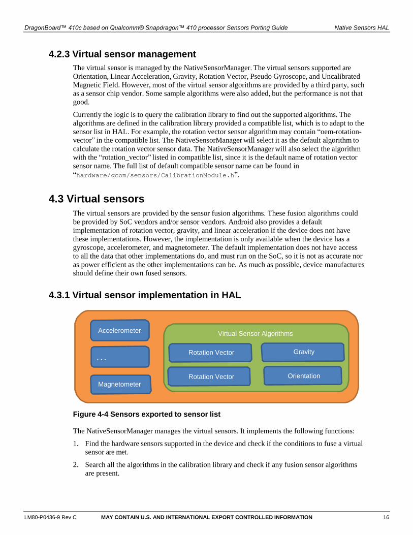
Figure 4-4 Sensors exported to sensor list
The NativeSensorManager manages the virtual sensors. It implements the following functions:
1. Find the hardware sensors supported in the device and check if the conditions to fuse a virtual
sensor are met.
2. Search all the algorithms in the calibration library and check if any fusion sensor algorithms
are present.
DragonBoard™ 410c based on Qualcomm® Snapdragon™ 410 processor Sensors Porting Guide Native Sensors HAL
LM80-P0436-9 Rev C MAY CONTAIN U.S. AND INTERNATIONAL EXPORT CONTROLLED INFORMATION 17
3. Register the virtual sensor algorithms.
4. Intercept the hardware sensors data flow and inject it into virtual sensor algorithms.
5. Send the calculated virtual sensor events to the Android framework.
6. Handle the virtual sensor enable/disable and polling delay settings.
4.3.2 How does the virtual sensor work?
Every virtual sensor has one or more background hardware sensors. Each hardware sensor
represents a Linux kernel implementation. These background sensors are called dependency
sensors. To activate a virtual sensor, the dependency sensor needs to be activated. The operation is
handled by Sensor HAL and is transparent to user space applications. The hardware sensor data
flows to the virtual sensor algorithms and calculates the result. The result will be sent to the
framework, which represents the sensor events of the virtual sensor.
4.3.3 Add customized virtual sensors
Customized virtual sensors can be added to the implementation. To add a customized virtual
sensor, follow these steps:
1. Add the algorithm to a calibration library. You can refer to: hardware/qcom/sensors/algo/common/common_wrapper.c.
2. Change calmodule.cfg to include the calibration library.
3. Modify the NativeSensorManager.cpp to add support for the virtual sensor. You can refer
to:
https://www.codeaurora.org/cgit/quic/la/platform/hardware/qcom/sensors/commit/?id=9be573f17
2ef7dd7dfe50c10f8469b7f21b5aa2a
LM80-P0436-9 Rev C MAY CONTAIN U.S. AND INTERNATIONAL EXPORT CONTROLLED INFORMATION 18
EXHIBIT 1
PLEASE READ THIS LICENSE AGREEMENT (“AGREEMENT”) CAREFULLY. THIS AGREEMENT IS A BINDING LEGAL AGREEMENT ENTERED INTO BY AND BETWEEN YOU (OR IF YOU ARE ENTERING INTO THIS AGREEMENT ON BEHALF OF AN ENTITY, THEN THE ENTITY THAT YOU REPRESENT) AND QUALCOMM TECHNOLOGIES, INC. (“QTI” “WE” “OUR” OR “US”). THIS IS THE AGREEMENT THAT APPLIES TO YOUR USE OF THE DESIGNATED AND/OR ATTACHED DOCUMENTATION AND ANY UPDATES OR IMPROVEMENTS THEREOF (COLLECTIVELY, “MATERIALS”). BY USING OR COMPLETING THE INSTALLATION OF THE MATERIALS, YOU ARE ACCEPTING THIS AGREEMENT AND YOU AGREE TO BE BOUND BY ITS TERMS AND CONDITIONS. IF YOU DO NOT AGREE TO THESE TERMS, QTI IS UNWILLING TO AND DOES NOT LICENSE THE MATERIALS TO YOU. IF YOU DO NOT AGREE TO THESE TERMS YOU MUST DISCONTINUE AND YOU MAY NOT USE THE MATERIALS OR RETAIN ANY COPIES OF THE MATERIALS. ANY USE OR POSSESSION OF THE MATERIALS BY YOU IS SUBJECT TO THE TERMS AND CONDITIONS SET FORTH IN THIS AGREEMENT.
1.1 License. Subject to the terms and conditions of this Agreement, including, without limitation, the restrictions, conditions, limitations and exclusions set forth in this Agreement, Qualcomm Technologies, Inc. (“QTI”) hereby grants to you a nonexclusive, limited license under QTI’s copyrights to use the attached Materials; and to reproduce and redistribute a reasonable number of copies of the Materials. You may not use Qualcomm Technologies or its affiliates or subsidiaries name, logo or trademarks; and copyright, trademark, patent and any other notices that appear on the Materials may not be removed or obscured. QTI shall be free to use suggestions, feedback or other information received from You, without obligation of any kind to You. QTI may immediately terminate this Agreement upon your breach. Upon termination of this Agreement, Sections 1.2-4 shall survive.
1.2 Indemnification. You agree to indemnify and hold harmless QTI and its officers, directors, employees and successors and assigns against any and all third party claims, demands, causes of action, losses, liabilities, damages, costs and expenses, incurred by QTI (including but not limited to costs of defense, investigation and reasonable attorney’s fees) arising out of, resulting from or related to: (i) any breach of this Agreement by You; and (ii) your acts, omissions, products and services. If requested by QTI, You agree to defend QTI in connection with any third party claims, demands, or causes of action resulting from, arising out of or in connection with any of the foregoing.
1.3 Ownership. QTI (or its licensors) shall retain title and all ownership rights in and to the Materials and all copies thereof, and nothing herein shall be deemed to grant any right to You under any of QTI's or its affiliates’ patents. You shall not subject the Materials to any third party license terms (e.g., open source license terms). You shall not use the Materials for the purpose of identifying or providing evidence to support any potential patent infringement claim against QTI, its affiliates, or any of QTI’s or QTI’s affiliates’ suppliers and/or direct or indirect customers. QTI hereby reserves all rights not expressly granted herein.
1.4 WARRANTY DISCLAIMER. YOU EXPRESSLY ACKNOWLEDGE AND AGREE THAT THE USE OF THE MATERIALS IS AT YOUR SOLE RISK. THE MATERIALS AND TECHNICAL SUPPORT, IF ANY, ARE PROVIDED "AS IS" AND WITHOUT WARRANTY OF ANY KIND, WHETHER EXPRESS OR IMPLIED. QTI ITS LICENSORS AND AFFILIATES MAKE NO WARRANTIES, EXPRESS OR IMPLIED, WITH RESPECT TO THE MATERIALS OR ANY OTHER INFORMATION OR DOCUMENTATION PROVIDED UNDER THIS AGREEMENT, INCLUDING BUT NOT LIMITED TO ANY WARRANTY OF MERCHANTABILITY OR FITNESS FOR A PARTICULAR PURPOSE OR AGAINST INFRINGEMENT, OR ANY EXPRESS OR IMPLIED WARRANTY ARISING OUT OF TRADE USAGE OR OUT OF A COURSE OF DEALING OR COURSE OF PERFORMANCE. NOTHING CONTAINED IN THIS AGREEMENT SHALL BE CONSTRUED AS (I) A WARRANTY OR REPRESENTATION BY QTI, ITS LICENSORS OR AFFILIATES AS TO THE VALIDITY OR SCOPE OF ANY PATENT, COPYRIGHT OR OTHER INTELLECTUAL PROPERTY RIGHT OR (II) A WARRANTY OR REPRESENTATION BY QTI THAT ANY MANUFACTURE OR USE WILL BE FREE FROM INFRINGEMENT OF PATENTS, COPYRIGHTS OR OTHER INTELLECTUAL PROPERTY RIGHTS OF OTHERS, AND IT SHALL BE THE SOLE RESPONSIBILITY OF YOU TO MAKE SUCH DETERMINATION AS IS NECESSARY WITH RESPECT TO THE ACQUISITION OF LICENSES UNDER PATENTS AND OTHER INTELLECTUAL PROPERTY OF THIRD PARTIES.
1.5 LIMITATION OF LIABILITY. IN NO EVENT SHALL QTI, QTI’S AFFILIATES OR ITS LICENSORS BE LIABLE TO YOU FOR ANY INCIDENTAL, CONSEQUENTIAL OR SPECIAL DAMAGES, INCLUDING BUT NOT LIMITED TO ANY LOST PROFITS, LOST SAVINGS, OR OTHER INCIDENTAL DAMAGES, ARISING OUT OF THE USE OR INABILITY TO USE, OR THE DELIVERY OR FAILURE TO DELIVER, ANY OF THE MATERIALS, OR ANY BREACH OF ANY OBLIGATION UNDER THIS AGREEMENT, EVEN IF QTI HAS BEEN ADVISED OF THE POSSIBILITY OF SUCH DAMAGES. THE FOREGOING LIMITATION OF LIABILITY SHALL REMAIN IN FULL FORCE AND EFFECT REGARDLESS OF WHETHER YOUR REMEDIES HEREUNDER ARE DETERMINED TO HAVE FAILED OF THEIR ESSENTIAL PURPOSE. THE ENTIRE LIABILITY OF QTI, QTI’s AFFILIATES AND ITS LICENSORS, AND THE SOLE AND EXCLUSIVE REMEDY OF YOU, FOR ANY CLAIM OR CAUSE OF ACTION ARISING HEREUNDER (WHETHER IN CONTRACT, TORT, OR OTHERWISE) SHALL NOT EXCEED US$10.
2. COMPLIANCE WITH LAWS; APPLICABLE LAW. You agree to comply with all applicable local, international and national laws and regulations and with U.S. Export Administration Regulations, as they apply to the subject matter of this Agreement. This Agreement is governed by the laws of the State of California, excluding California’s choice of law rules.
3. CONTRACTING PARTIES. If the Materials are downloaded on any computer owned by a corporation or other legal entity, then this Agreement is formed by and between QTI and such entity. The individual accepting the terms of this Agreement represents and warrants to QTI that they have the authority to bind such entity to the terms and conditions of this Agreement.
4. MISCELLANEOUS PROVISIONS. This Agreement, together with all exhibits attached hereto, which are incorporated herein by this reference, constitutes the entire agreement between QTI and You and supersedes all prior negotiations, representations and agreements between the parties with respect to the subject matter hereof. No addition or modification of this Agreement shall be effective unless made in writing and signed by the respective representatives of QTI and You. The restrictions, limitations, exclusions and conditions set forth in this Agreement shall apply even if QTI or any of its affiliates becomes aware of or fails to act in a manner to address any violation or failure to comply therewith. You hereby acknowledge and agree that the restrictions, limitations, conditions and exclusions imposed in this Agreement on the rights granted in this Agreement are not a derogation of the benefits of such rights. You further acknowledges that, in the absence of such restrictions, limitations, conditions and exclusions, QTI would not have entered into this Agreement with You. Each party shall be responsible for and shall bear its own expenses in connection with this Agreement. If any of the provisions of this Agreement are determined to be invalid, illegal, or otherwise unenforceable, the remaining provisions shall remain in full force and effect. This Agreement is entered into solely in the English language, and if for any reason any other language version is prepared by any party, it shall be solely for convenience and the English version shall govern and control all aspects. If You are located in the province of Quebec, Canada, the following applies: The Parties hereby confirm they have requested this Agreement and all related documents be prepared in English.