Sensor Technology and Axle ounting. We provide more than ...
26
www.pintsch.net AZ II Axle Counting System for use as track vacancy detection equipment Sensor Technology and Axle Counting. We provide more than just impulses.
Transcript of Sensor Technology and Axle ounting. We provide more than ...

www.pintsch.net
AZ II Axle Counting System for use as track vacancy detection equipment
Sensor Technology and Axle Counting.
We provide more than just impulses.
www.pintsch.net | 2
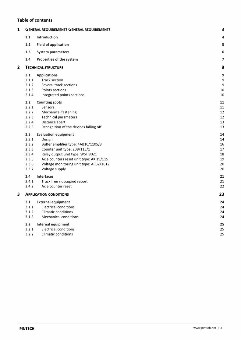
Table of contents
1 GENERAL REQUIREMENTS GENERAL REQUIREMENTS 3
1.1 Introduction 4
1.2 Field of application 5
1.3 System parameters 6
1.4 Properties of the system 7
2 TECHNICAL STRUCTURE 8
2.1 Applications 9 2.1.1 Track section 9 2.1.2 Several track sections 9 2.1.3 Points sections 10 2.1.4 Integrated points sections 10
2.2 Counting spots 11 2.2.1 Sensors 11 2.2.2 Mechanical fastening 12 2.2.3 Technical parameters 12 2.2.4 Distance apart 13 2.2.5 Recognition of the devices falling off 13
2.3 Evaluation equipment 14 2.3.1 Design 14 2.3.2 Buffer amplifier type: 4AB10/1105/3 16 2.3.3 Counter unit type: ZB8/115/1 17 2.3.4 Relay output unit type: WST 8021 18 2.3.5 Axle counters reset unit type: AK 19/115 19 2.3.6 Voltage monitoring unit type: AR32/1612 20 2.3.7 Voltage supply 20
2.4 Interfaces 21 2.4.1 Track free / occupied report 21 2.4.2 Axle counter reset 22
3 APPLICATION CONDITIONS 23
3.1 External equipment 24 3.1.1 Electrical conditions 24 3.1.2 Climatic conditions 24 3.1.3 Mechanical conditions 24
3.2 Internal equipment 25 3.2.1 Electrical conditions 25 3.2.2 Climatic conditions 25
www.pintsch.net | 3
1 General requirements General requirements
www.pintsch.net | 4
1.1 Introduction
The firm of PINTSCH GmbH makes axle counting systems based on double wheel sensors (DSS) and various electronic units for
processing the DSS-signals to give a track free/occupied report for tracks in railway operation. This product information
describes the AZ II (" Achs-Zählsystem Generation II") axle counting system, which comes from simplified technology for
shunting areas with Local electrically Operated Point-Switches (LOPS), and in its further developed version AZ in passenger traffic
is already installed in many places and has withstood its probationary test there.
The latest generation with name AZ II is an upgraded version of the AZ with new functions representing the state of the art in
axle counting systems.

www.pintsch.net | 5
1.2 Field of application
The electronic axle counting system AZ II is designed for vacancy detection equipment for use with any heavy railways and light
rail systems. The product was developed to meet the requirements of the following standards and specifications:
Standard/Specification Designation Publisher
EBO Railway construction and operating regulations Eisenbahn-
bundesamt
(EBA)
VDV 361 Railway signalling equipment
Signalling principles for non-state owned railways
VDV
DIN VDE 0106 Protection against electric shock DIN
DIN VDE 0110 Insulation co-ordinates for electrical equipment DIN
DIN VDE 0115 Railways DIN
DIN VDE 0831 Electric railway signalling equipment DIN
DIN VDE 0831A1 Electric railway signalling equipment DIN
DIN EN 50121 Railway applications: electromagnetic compatibility CENELEC
DIN EN 50124 Railway applications: Insulation co-ordinates CENELEC

www.pintsch.net | 6
1.3 System parameters
The AZ II axle counting system achieves the following functions:
- Registration of the occupation information and the counter impulses of connected double wheel sensors (DSS) and the processing of these impulses in an electronic axle counter.
- Management of a counting circuit to determine the track free/occupied condition for a section (counting circuit function).
- Installation in the speed range 0..250 km/h
- Counting capacity of 4096 axles for a counting circuit (ring counter)
- Two internal counting devices for simultaneous, direction dependent in and out counting over different counting spots of a
counting circuit
- A voltage free secure output interface for track free and occupied reporting
- Fail-safe input interface for RESET after defects

www.pintsch.net | 7
1.4 Properties of the system
Availability
When the AZ II axle counting system is operated as specified it has an availability of a maximum of one error counting per 107
axles for one counting circuit or a maximum of one system failure per year.
When considering the failure behaviour in respect of the operational availability it must be considered that for each axle
counting circuit there is a separate axle counting group. Theoretically possible defects consequently affect only one, or with
counting spot defects of double used rail contacts, a maximum of two axle counting circuits of a complete system. With two or
multitrack lines with bi-directional operation the neighbouring track can, in addition, be projected as independent segments of
axle counting systems and consequently the principle of topographical redundancy is achieved.
Maintenance cost
The internal equipment is maintenance free within the maintenance period up to the necessary checking of a monitoring
function ("Stö"-relay). The external equipment requires the DSS to be checked once within the maintenance period of one year
to see that it is working properly and securely fixed.
The modular construction of the axle counting system should limit the repair - when necessary - to the exchange of the plug-in
cards. The fault finding is reduced by the display of important system conditions by different LEDs, and is assisted by different
test buttons on the front of the unit cards so that the times required for fault finding are reduced. Due to the equipment works
without a micro computer, the high running times or times for the off-line tests after a repair are not required and the
equipment is immediately available for service again after operation of the RESET keys.
Systems design
The counting spots (DSS) are connected to the axle counting system in a standard way, which enables the use of ready-made
cables between the cable connection frame and the internal equipment. The assignment of the counting spots to the section
(counting direction) is done during the systems design.
Scaleability
For each counting circuit there are two independent counters available which enable simultaneous, direction independent, in or
out counting over the connected DSS A and B, as is necessary, for example with very short track vacancy detection sections
(points, intermediate tracks).
If a counting circuit needs more than two DSS (e.g. with a point or a point area) these can be connected parallel to the counting
units A and B. The number of counting spots which can be connected in parallel is theoretically unlimited. Parallel connected
counting spots must not, however, be run over at the same time which in the normal operating cases, and with corresponding
planning of the track vacancy detection section inside interlocking or block systems, does not occur.
Axle Counters Reset ACR
The conditions, under which an operation of the ACR key actually leads to the reset of the axle counter, are laid down in an
internal axle counter reset logic. They are modelled on the applicable operating requirements and specifications of the
individual railway companies. Independent of the data in the following overview the RESET occurs only when there are no
defects in all the counting spots that belong to the section and none of these counting spots is continuously occupied.
The following variants for the RESET can be planned:
a) Absolute axle counters reset:
After operation of the ACR key the counter of the axle counter circuit is set to zero and the track free report of the axle counting section is given
b) Conditional axle counter reset: After operation of the ACR key the counter of the axle counter circuit is set to zero, only when the last detected wheel has been an out counted wheel (minus). c) Preparatory axle counters reset:
After operation of the ACR key the counter of the axle counter circuit is set to zero. The track free report is given only when the next journey has led to the occupation, counting in at counting spot A, counting out at counting spot B (running through the complete section) and free running.

www.pintsch.net | 8
Double use of the counting spots
A segment of a buffer amplifier is assigned to each counting spot (DSS). A buffer amplifier card is thus made up of two
segments, that is to say two DSSs can be connected to a buffer amplifier independent of which counting circuit the segments are
used for.
The output signals of the buffer amplifiers can be connected to various counting groups, and in this way a repeated use of DSS
and buffer amplifiers is achieved. The switching of the counting groups is done by optoelectronic couplers that are potentially
separated and reactionless.
2 Technical structure The axle counting system consists of the DSS, the quasi two channel buffer amplifiers, a two channel electronic axle counter, the
relay track vacancy detection unit, the axle counter RESET unit and the voltage supply.
The following Figure shows the structure of the axle counter system.
Counter unit
Buffer amplifier
Axle countersreset unit
Relay output unit
Channel A Channel B
free occupied
Inside equipment
Voltage supply
230 V AC or 20-72 V DC
S I S II S I S II
Outside equipment
I II I II
DSS 1 DSS 2
ACR
free occupied
DSS 1 DSS 2 RESET
12 V DC 24 V DC
free occupied
Figure 1: AZ II block circuit diagram
www.pintsch.net | 9
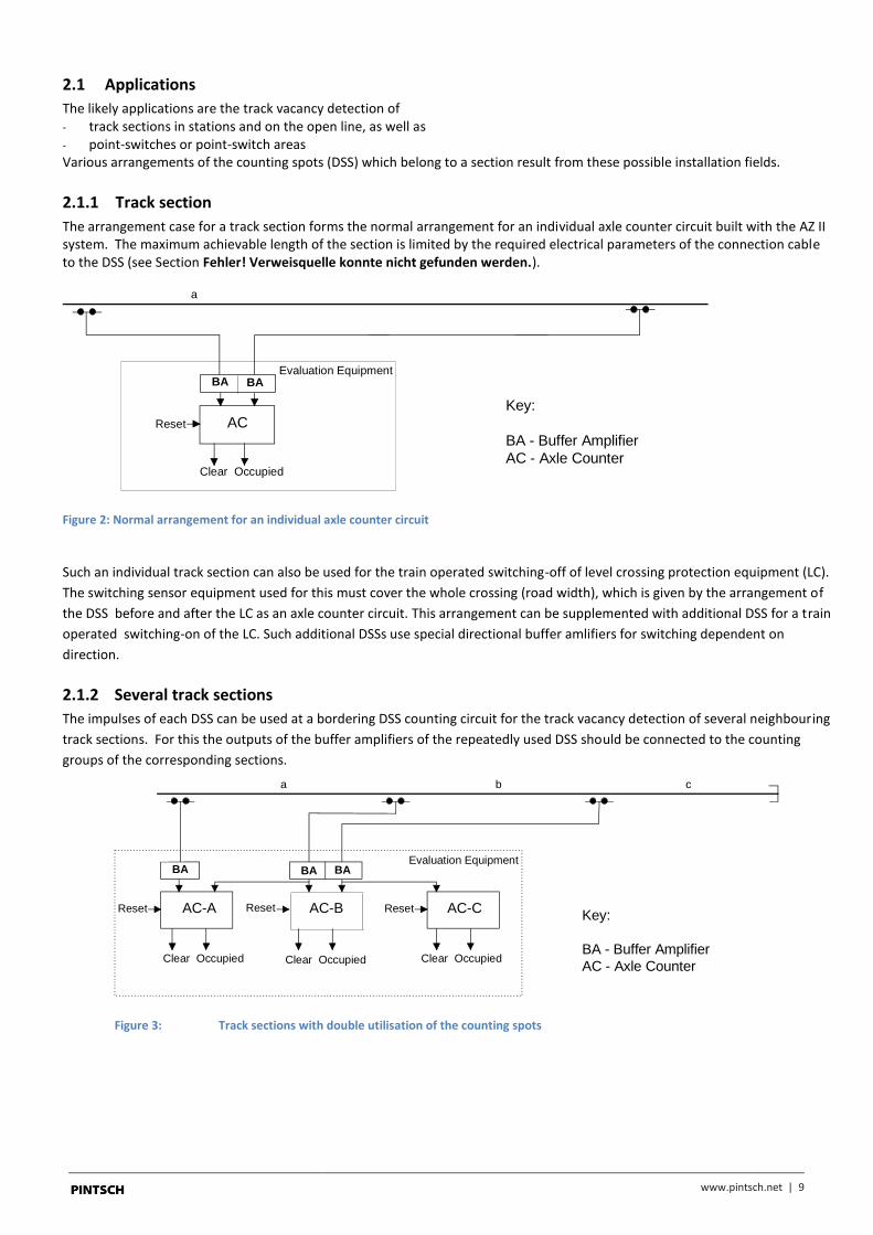
2.1 Applications
The likely applications are the track vacancy detection of - track sections in stations and on the open line, as well as - point-switches or point-switch areas Various arrangements of the counting spots (DSS) which belong to a section result from these possible installation fields.
2.1.1 Track section
The arrangement case for a track section forms the normal arrangement for an individual axle counter circuit built with the AZ II system. The maximum achievable length of the section is limited by the required electrical parameters of the connection cable to the DSS (see Section Fehler! Verweisquelle konnte nicht gefunden werden.).
ACReset
Clear Occupied
a
Evaluation EquipmentBA BA
Key:
BA - Buffer Amplifier
AC - Axle Counter
Figure 2: Normal arrangement for an individual axle counter circuit
Such an individual track section can also be used for the train operated switching-off of level crossing protection equipment (LC).
The switching sensor equipment used for this must cover the whole crossing (road width), which is given by the arrangement of
the DSS before and after the LC as an axle counter circuit. This arrangement can be supplemented with additional DSS for a train
operated switching-on of the LC. Such additional DSSs use special directional buffer amlifiers for switching dependent on
direction.
2.1.2 Several track sections
The impulses of each DSS can be used at a bordering DSS counting circuit for the track vacancy detection of several neighbouring
track sections. For this the outputs of the buffer amplifiers of the repeatedly used DSS should be connected to the counting
groups of the corresponding sections.
AC-A AC-BReset
Clear Occupied
ba c
Evaluation EquipmentBA
AC-C
Clear Occupied Clear Occupied
Reset Reset
BA BA
Key:
BA - Buffer Amplifier
AC - Axle Counter
Figure 3: Track sections with double utilisation of the counting spots

www.pintsch.net | 10
2.1.3 Points sections
Both individual points and double slip points can be fitted with the AZ II system.
AC-W1Reset
BA
AC-KW2 AC-W3
W1
KW2
W3
Clear Occupied
EvaluationEquipmentBA BA BA BA BA BA BA
Reset Reset
Clear Occupied Clear Occupied
Figure 4: Track vacancy detection of points ("W") and double slip points ("KW")
2.1.4 Integrated points sections
The arrangement as shown in Figure 6 offers the possibility of a cost effective solution for track vacancy detection in integrated
points sections. Up to 8 DSS can be connected to one evaluation unit to be integrated and processed simultaneously in such an
arrangement.
BA
AC-WBReset
Clear Occupied
Evaluation Equipment
BA BA BA BA BA
Key:
BA - Buffer Amplifier
AC - Axle Counter
Figure 5: Integrated points section (“WB”) with connected counting spots

www.pintsch.net | 11
2.2 Counting spots
2.2.1 Sensors
The Pintsch double wheel sensors (DSS) well-tried in thousands of applications (see DSS reference documents) are used in the
counting spots of the AZ II axle counting system. The DSSs enable direction dependent detection of rail wheels at the given
point.
The DSS is connected with its connection cables through a signal cable junction box directly with the signal cable that leads
directly to the assessment device (internal equipment). Beside the DSS no additional equipment is necessary on the track which
makes the system maintenance friendly.
Double wheel sensorCable junction box
Figure 6: DSS on the track (sketch)
The DSS consists of two galvanically separate sensor systems that are independent of one another. The independence of the
individual systems is the basis for certain safety considerations and therefore must not be cancelled by all the influences that
affect railway operation. One component of the DSS is a fixed connected, cast flexible connection cable 5 m long. No electronics
is necessary on the rail side for signal preparation or assessment.
www.pintsch.net | 12
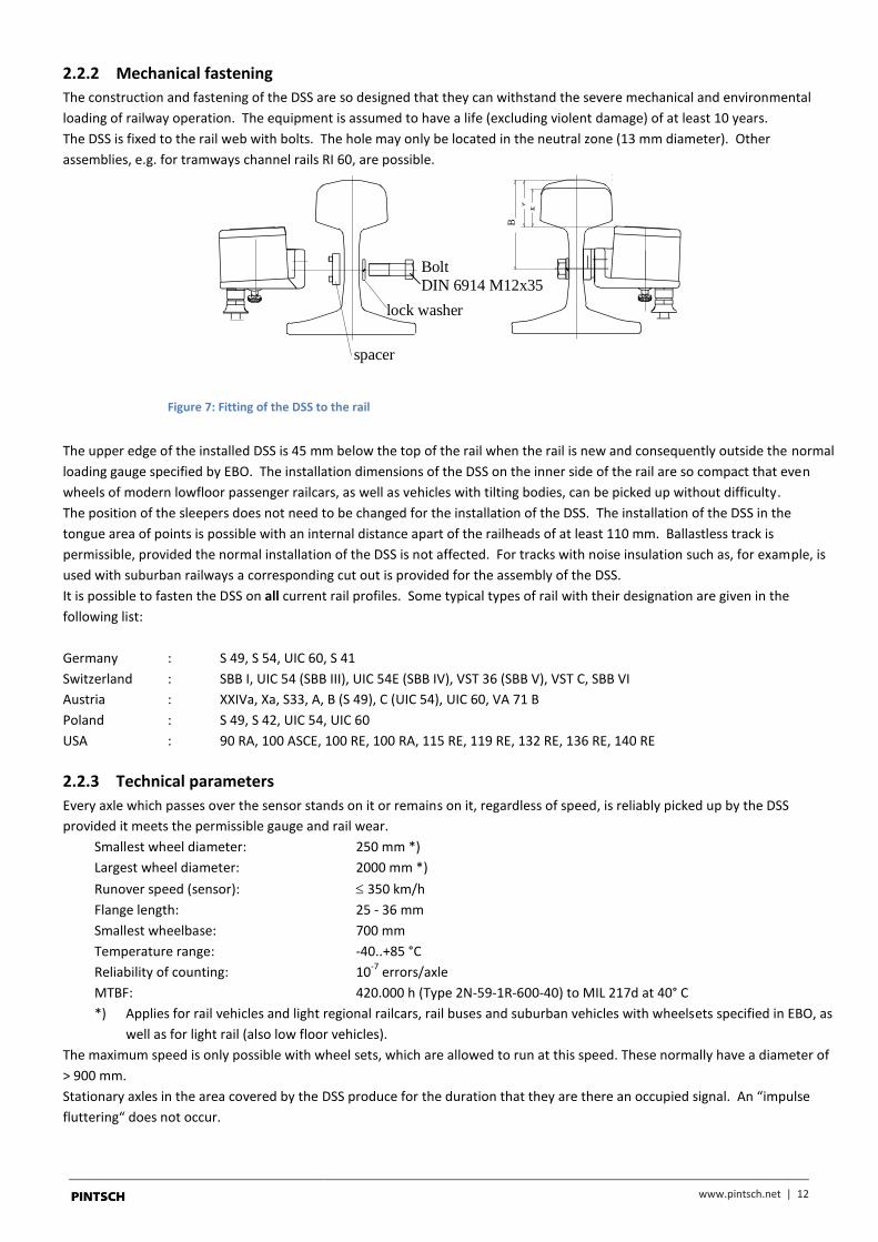
2.2.2 Mechanical fastening
The construction and fastening of the DSS are so designed that they can withstand the severe mechanical and environmental
loading of railway operation. The equipment is assumed to have a life (excluding violent damage) of at least 10 years.
The DSS is fixed to the rail web with bolts. The hole may only be located in the neutral zone (13 mm diameter). Other
assemblies, e.g. for tramways channel rails RI 60, are possible.
lock washer
Bolt
DIN 6914 M12x35
spacer
B
Figure 7: Fitting of the DSS to the rail
The upper edge of the installed DSS is 45 mm below the top of the rail when the rail is new and consequently outside the normal
loading gauge specified by EBO. The installation dimensions of the DSS on the inner side of the rail are so compact that even
wheels of modern lowfloor passenger railcars, as well as vehicles with tilting bodies, can be picked up without difficulty.
The position of the sleepers does not need to be changed for the installation of the DSS. The installation of the DSS in the
tongue area of points is possible with an internal distance apart of the railheads of at least 110 mm. Ballastless track is
permissible, provided the normal installation of the DSS is not affected. For tracks with noise insulation such as, for example, is
used with suburban railways a corresponding cut out is provided for the assembly of the DSS.
It is possible to fasten the DSS on all current rail profiles. Some typical types of rail with their designation are given in the
following list:
Germany : S 49, S 54, UIC 60, S 41
Switzerland : SBB I, UIC 54 (SBB III), UIC 54E (SBB IV), VST 36 (SBB V), VST C, SBB VI
Austria : XXIVa, Xa, S33, A, B (S 49), C (UIC 54), UIC 60, VA 71 B
Poland : S 49, S 42, UIC 54, UIC 60
USA : 90 RA, 100 ASCE, 100 RE, 100 RA, 115 RE, 119 RE, 132 RE, 136 RE, 140 RE
2.2.3 Technical parameters
Every axle which passes over the sensor stands on it or remains on it, regardless of speed, is reliably picked up by the DSS
provided it meets the permissible gauge and rail wear.
Smallest wheel diameter: 250 mm *)
Largest wheel diameter: 2000 mm *)
Runover speed (sensor): 350 km/h
Flange length: 25 - 36 mm
Smallest wheelbase: 700 mm
Temperature range: -40..+85 °C
Reliability of counting: 10-7
errors/axle
MTBF: 420.000 h (Type 2N-59-1R-600-40) to MIL 217d at 40° C
*) Applies for rail vehicles and light regional railcars, rail buses and suburban vehicles with wheelsets specified in EBO, as
well as for light rail (also low floor vehicles).
The maximum speed is only possible with wheel sets, which are allowed to run at this speed. These normally have a diameter of
> 900 mm.
Stationary axles in the area covered by the DSS produce for the duration that they are there an occupied signal. An “impulse
fluttering“ does not occur.

www.pintsch.net | 13
2.2.4 Distance apart
The distance apart is designated in the case of the AZ II axle counting system as the maximum cable length between the input
place (DSS) and output device (internal equipment). The distance apart is limited by the ohmic resistance of the connection
cable. The cable resistance of the cable may be up to 200 Ohms.
The achievable distance apart is obtained from this value and the type of star quad signal cable installed. In the following table
they are given for some typical core diameters as examples. The recommended core diameter is 0.9 mm.
wire diameter
d / mm
Loop resitance
R / Ohms
Distance apart
s / m
0,9 200 3563
1,4 200 8621
Table 1: Distance apart for typical copper cable
In special cases the achievable distance apart can be increased up to 15 km by connecting an amplifier module which is installed
in a cable junction box (for core diameters of 1.4 mm). However, the amplifier module requires a local supply voltage.
2.2.5 Recognition of the devices falling off
The sensor systems of the DSS are predamped by the metal mass of the rail. If this predamping is not present the sensor system
produces at its output a signal picture which corresponds to the permanent occupation of a stationary axle. If the DSS falls off or
is removed from the rails or is improperly assembled on the rail this is consequently recognised by the axle counting system.
The occupation produced is only lifted for all counting circuits affected after the operating staff have repaired the defect and put
the equipment into the RESET.
www.pintsch.net | 14
2.3 Evaluation equipment
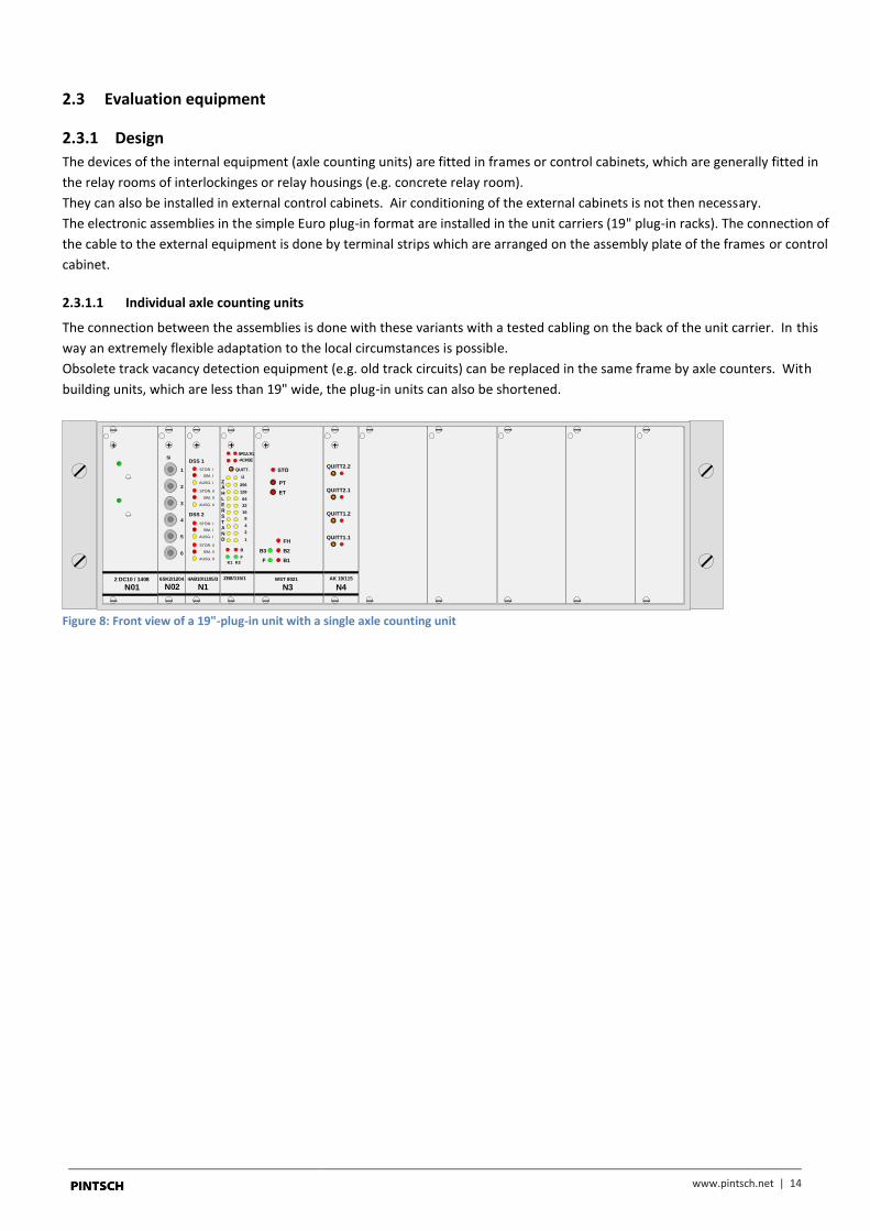
2.3.1 Design
The devices of the internal equipment (axle counting units) are fitted in frames or control cabinets, which are generally fitted in
the relay rooms of interlockinges or relay housings (e.g. concrete relay room).
They can also be installed in external control cabinets. Air conditioning of the external cabinets is not then necessary.
The electronic assemblies in the simple Euro plug-in format are installed in the unit carriers (19" plug-in racks). The connection of
the cable to the external equipment is done by terminal strips which are arranged on the assembly plate of the frames or control
cabinet.
2.3.1.1 Individual axle counting units
The connection between the assemblies is done with these variants with a tested cabling on the back of the unit carrier. In this
way an extremely flexible adaptation to the local circumstances is possible.
Obsolete track vacancy detection equipment (e.g. old track circuits) can be replaced in the same frame by axle counters. With
building units, which are less than 19" wide, the plug-in units can also be shortened.
DSS 1
DSS 2
STÖR. II
SIM. II
AUSG. II
STÖR. I
SIM. I
AUSG. I
STÖR. II
SIM. II
AUSG. II
STÖR. I
SIM. I
AUSG. I
N14AB10/1105/3
1
2
3
4
5
6
6SK2/1204
Si
N02WST 8021
STÖ
PT
ET
B2
B1F
FH
B3
N3
AK 19/115
QUITT2.2
QUITT2.1
QUITT1.2
QUITT1.1
N42 DC10 / 1408
N01 N2ZB8/115/1
B
F
QUITT.
SPG./LTG.
-ACHSE
1
2
4
8
16
32
64
128
256
Ü
K1 K2
ZÄ
H
LE
RS
TA
ND
Figure 8: Front view of a 19"-plug-in unit with a single axle counting unit

www.pintsch.net | 15
2.3.1.2 Multiple axle counting units
The connections between the assemblies of the unit carrier are done by backpanes. The cabling and the test work is kept low by
the use of standardised backplanes (84 TE) for each of 6 buffer amplifier cards (12 DSSs) and 4 axle counter units (assemblies for
a counting circuit).
The voltage supply of the individual function groups (Figure 10, upper plug-in unit left) is done by voltage supply cards plugged in
to a seperate rack and are connected to the backpanes by wireing.
Consequently the voltage supply units can be chosen to have different power levels depending on the number of axle counting
systems to be supplied.
ZB8/115/1
B
F
QUITT.
SPG./LTG.
-ACHSE
1
2
4
8
16
32
64
128
256
Ü
K1 K2
Z
ÄH
LE
R
ST
AN
D
ZB8/115/1
B
F
QUITT.
SPG./LTG.
-ACHSE
1
2
4
8
16
32
64
128
256
Ü
K1 K2
Z
ÄH
LE
R
ST
AN
D
N2ZB8/115/1
B
F
QUITT.
SPG./LTG.
-ACHSE
1
2
4
8
16
32
64
128
256
Ü
K1 K2
Z
ÄH
LE
R
ST
AN
D
N2ZB8/115/1
B
F
QUITT.
SPG./LTG.
-ACHSE
1
2
4
8
16
32
64
128
256
Ü
K1 K2
Z
ÄH
LE
R
ST
AN
D
1
2
3
4
5
6
6SK2/1204
Si
N01
DSS 1
DSS 2
4AB10/1105/3
STÖR. II
SIM. II
AUSG. II
STÖR. I
SIM. I
AUSG. I
STÖR. II
SIM. II
AUSG. II
STÖR. I
SIM. I
AUSG. I
N1 N1Ü1 N1Ü2 N1Ü3 N1Ü4 N1Ü7
Zp GL. 2
Zp 1100 Sp
Zp 1100 -
Zp 1100 +
Zp GL. 1
Zp 1101 -
Zp 1101 +
Zp 1102 Sp
E1
E2
N1Ü5
Zp 1104 Sp
Zp 1104 +
N1Ü6
Zp 1105 +
Zp 1105 -
DSS 1
DSS 2
4AB10/1105/3
STÖR. II
SIM. II
AUSG. II
STÖR. I
SIM. I
AUSG. I
STÖR. II
SIM. II
AUSG. II
STÖR. I
SIM. I
AUSG. I
N2
DSS 1
DSS 2
4AB10/1105/3
STÖR. II
SIM. II
AUSG. II
STÖR. I
SIM. I
AUSG. I
STÖR. II
SIM. II
AUSG. II
STÖR. I
SIM. I
AUSG. I
N3
DSS 1
DSS 2
4AB10/1105/3
STÖR. II
SIM. II
AUSG. II
STÖR. I
SIM. I
AUSG. I
STÖR. II
SIM. II
AUSG. II
STÖR. I
SIM. I
AUSG. I
N4
DSS 1
DSS 2
4AB10/1105/3
STÖR. II
SIM. II
AUSG. II
STÖR. I
SIM. I
AUSG. I
STÖR. II
SIM. II
AUSG. II
STÖR. I
SIM. I
AUSG. I
N5
DSS 1
DSS 2
4AB10/1105/3
STÖR. II
SIM. II
AUSG. II
STÖR. I
SIM. I
AUSG. I
STÖR. II
SIM. II
AUSG. II
STÖR. I
SIM. I
AUSG. I
N6
AK 19/115
QUITT2.2
QUITT2.1
QUITT1.2
QUITT1.1
WST 8021
STÖ
PT
ET
B2
B1F
FH
B3
1
2
3
4
4SK3/1004
Si
N01WST 8021
STÖ
PT
ET
B2
B1F
FH
B3
N1 N2 N3 N4 N5 Ü2Ü1AK 19/115
QUITT2.2
QUITT2.1
QUITT1.2
QUITT1.1
WST 8021
STÖ
PT
ET
B2
B1F
FH
B3
WST 8021
STÖ
PT
ET
B2
B1F
FH
B3
N6 N7 N8 N9 N10 Ü4Ü3
Verb.2/1100
Verb.1/1101
W 1101
W 1100
E3
DC17 / 1408
12V
DC18 / 1408
24V
N01 N02
SPU1ST1
SPU2ST2
SPU3ST3
SPU4ST4
SPU5ST5
SPU6ST6
AR32/1612
N03 E2
Figure 9: Design of a multiple axle counting unit

www.pintsch.net | 16
2.3.2 Buffer amplifier type: 4AB10/1105/3
The buffer amplifier units are allocated to the DSSs. A buffer amplifier unit contains two inputs for the switching of each double
wheel sensor (DSS). The two sensor systems of a DSS are taken over separate signal paths so that a quasi two channel system is
achieved regarding the failure revelation.
If one axle counting system receives its DSS impulses from buffer amplifiers of neighbouring DSS (multiple use), no dedicated
buffer amplifier needs to be provided for this counting circuit. The buffer amplifier adapts the analogue DSS signals to the digital
inputs of the counting unit and decouples the internal and external equipment. The DSS systems are fed with constant current.
Depending on the damping the internal resistance of the DSS systems changes and consequently the voltage drop across the
constant current source. From this voltage drop, the reports track free or occupied are produced for each part system of the
DSS.
In addition a monitoring of the sensor systems of the DSS takes place on the buffer amplifier for wire breakage, wire short
circuit, and depending on the corresponding DSS type, orderly fastening of the DSS to the rail.
The track occupied report of the axle counter circuit takes place by damping of one of the two sensor systems of the double
wheel sensor (DSS). The buffer amplifier works directly on the relay chain of the output assembly and on the input of the
counting unit through independent optocouplers.
The connection between the buffer amplifier cards and the terminal strip is usually done by ready made connection cables.
Front view LED/key Explanation
DSS 1
DSS 2
4AB10/1105/3
STÖR. II
SIM. II
AUSG. II
STÖR. I
SIM. I
AUSG. I
STÖR. II
SIM. II
AUSG. II
STÖR. I
SIM. I
AUSG. I
N1
DSS1
STÖR I
SIM I
AUSG I
STÖR II
SIM II
AUSG II
DSS 2
Red LED lights if a cable breaks or if a wire short circuits on DSS 1
System I
With this key an occupation of the DSS 1 System I can be simulated.
Yellow LED lights if there is a wire short circuit, wire break and with
DSS 1 System I occupied.
Red LED lights if a cable breaks or if a wire short circuits on DSS 1
System I
With this key an occupation of the DSS 1 System II can be simulated.
Yellow LED lights if there is a wire short circuit, wire break and with
DSS 1 System I occupied.
As DSS 1 however on DSS 2

www.pintsch.net | 17
2.3.3 Counter unit type: ZB8/115/1
The fail-safe electronic counter unit is the centre piece of the axle counting system. The counting direction is derived on the
counting unit from the position of the switchflanks of both DSS part systems to one another. By direction independent running
over the double wheel sensors the axles of two channel electronic counters are counted in or counted out. In this way it is
possible to count in or count out over two DSSs of the axle counter circuit at the same time.
A track free report is given after the same number of axles have come in and gone out by fail-safe comparison of the counter
condition in both channels, when the last recognised counting process was a counting out process.
Front view LED/key Explanation
N 2Z B 8 / 1 1 5 / 1
B
F
Q U I T T .
S P G . / L T G .
- A C H S E
1
2
4
8
1 6
3 2
6 4
1 2 8
2 5 6
Ü
K 1 K 2
Z
ÄH
LE
R
ST
AN
D
SPG.STÖ
- ACHSE
QUITT
Ü
ZÄHLER-
STAND
B
F
K1, K2
Red LED lights after switching on or after a voltage failure of the supply
voltage and after a minus axle.
A local reset signal is produced by the "Quitt" key. This resets the counter
as well as the flip-flops of the voltage and DSS wire defect.
”Überwacher” by means of “control relay”
Yellow LED lights if the control relay drops down due to the flank sequence
on the inputs does not occur in the correct sequence. (Touching one or
both DSS systems without completely passing over. DSS systems of
unequal switching distance).
"Count"; The LED's show the stages of a 9 stage binary counter (511 axles).
The counters adjacent to the LEDs indicate the significance.
”Besetzt” means “Occupied”; Red LED's light if the counter position of the
in and out counters is not the same or a monitoring relay is set.
“Frei” means “Clear”; Green LED's light if the counter position of the in and
out counters is the same and no monitor is on.
”Kanal 1, Kanal 2”, Column of LEDs shown for each of the two processing
chanels
(2 of 2 safety related device)
www.pintsch.net | 18
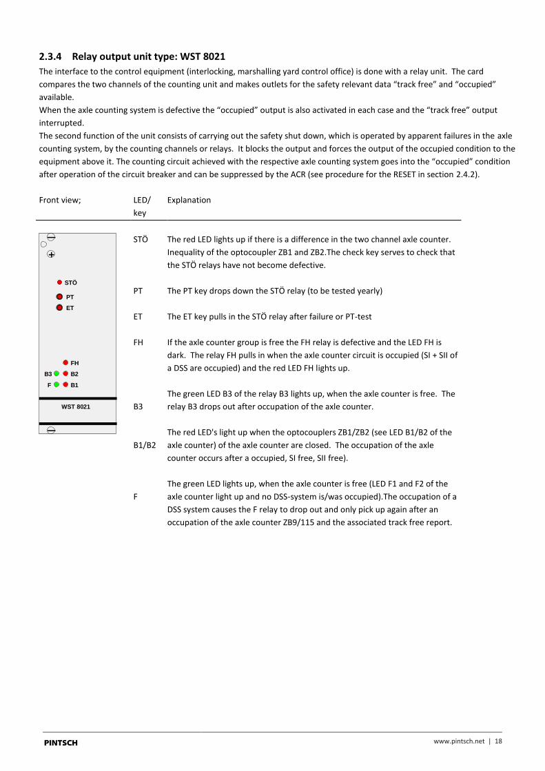
2.3.4 Relay output unit type: WST 8021
The interface to the control equipment (interlocking, marshalling yard control office) is done with a relay unit. The card
compares the two channels of the counting unit and makes outlets for the safety relevant data “track free” and “occupied”
available.
When the axle counting system is defective the “occupied” output is also activated in each case and the “track free” output
interrupted.
The second function of the unit consists of carrying out the safety shut down, which is operated by apparent failures in the axle
counting system, by the counting channels or relays. It blocks the output and forces the output of the occupied condition to the
equipment above it. The counting circuit achieved with the respective axle counting system goes into the “occupied” condition
after operation of the circuit breaker and can be suppressed by the ACR (see procedure for the RESET in section 2.4.2).
Front view; LED/
key
Explanation
WST 8021
STÖ
PT
ET
B2
B1F
FH
B3
STÖ
PT
ET
FH
B3
B1/B2
F
The red LED lights up if there is a difference in the two channel axle counter.
Inequality of the optocoupler ZB1 and ZB2.The check key serves to check that
the STÖ relays have not become defective.
The PT key drops down the STÖ relay (to be tested yearly)
The ET key pulls in the STÖ relay after failure or PT-test
If the axle counter group is free the FH relay is defective and the LED FH is
dark. The relay FH pulls in when the axle counter circuit is occupied (SI + SII of
a DSS are occupied) and the red LED FH lights up.
The green LED B3 of the relay B3 lights up, when the axle counter is free. The
relay B3 drops out after occupation of the axle counter.
The red LED's light up when the optocouplers ZB1/ZB2 (see LED B1/B2 of the
axle counter) of the axle counter are closed. The occupation of the axle
counter occurs after a occupied, SI free, SII free).
The green LED lights up, when the axle counter is free (LED F1 and F2 of the
axle counter light up and no DSS-system is/was occupied).The occupation of a
DSS system causes the F relay to drop out and only pick up again after an
occupation of the axle counter ZB9/115 and the associated track free report.

www.pintsch.net | 19
2.3.5 Axle counters reset unit type: AK 19/115
As input interface the axle counter reset unit offers a safe input for the Axle Counter Reset key (ACR). The external ACR-key or
the "Quit" keys on the front face of the unit causes not only a reset of the counter but simultaneously the controlled put back of
the switching and the track vacancy detection. A condition for the track vacancy detection is the correct functioning of the
counters. These are checked by simulation of the counting in and counting out procedures with 2 axles by the axle counter reset
unit.
The 2-axle check of the counter unit is not implemented in case of a systems design with preparing axle counters reset (see
section 1.4). In this case the pressed "Quit" keys or set ACR inputs only effect a reset of the counter unit to zero. The test
counting has to be done by the next train passing the whole axle counter circuit or by simulating axles with the "SIM" keys on
the buffer amplifier cards.
The axle counting reset unit can achieve the above mentioned functions for up to two counting circuits which leads to better
space utilisation of the units and contributes to a cost effective solution.
Front view; LED/
key
Explanation
AK 19/115
QUITT2.2
QUITT2.1
QUITT1.2
QUITT1.1
QUITT 1
QUITT 2
If the key QUITT 1 and QUITT 2 are operated the relays Q1.1
and Q1.2 pull in. Through the relay contacts the axle counter
is put back, the relay card is switched to the RESET and then
an in and out counting of 2 axles is simulated on the axle
counter.
The LED's are connected parallel to the relays Q1.1 and Q1.2.

www.pintsch.net | 20
2.3.6 Voltage monitoring unit type: AR32/1612
The relay unit AR32/1612 is set to monitor the supply voltage of the buffer amplifiers.
With double use of DSS this relay card causes a voltage switching of the axle counters concerned and consequently a track
occupied report of the axle counters
- when the supply voltage of the buffer amplifier fails or - if the buffer amplifier is missing (e.g. card taken out),
Front view; LED/
key
Explanation
SPU1ST1
SPU2ST2
SPU3ST3
SPU4
ST4
SPU5ST5
SPU6
ST6
AR32/1612
N03 E2
SPU 1-6
ST 1-6
The green LED`s light up when the SPU relay is closed, thus the
voltage supply is available for the buffer amplifiers.
With operation of an ST.. key a defect check of the
corresponding SPU relay takes place. The defect of the SPU ..
relay is indicated by a red LED SPU.. and the appropriate axle
counter circuit is occupied. With the release of the SPU.. key the
SPU.. relay again pulls in.
After carrying out the defect check of the SPU relay the axle
counter circuit must be brought into the RESET again by an
AzGrT operation.
2.3.7 Voltage supply
The voltage supply provides the supply voltages for the axle counting system. It is so designed that the different international
input voltages can be used. Units are designed for the following input voltages:
- 20-72 VDC (typically: 24 VDC or 60 VDC) - 170-265 VAC (typically: 230 VAC) - 110 VAC In general, the input voltage should be provided uninterupted (UPS). For applications in which that is not possible, a battery
buffered supply voltage can be used. The axle counting system can consequently continue to be operated when there are
failures of the voltage supply for the maximum necessary time without restriction.

www.pintsch.net | 21
2.4 Interfaces
2.4.1 Track free / occupied report
The issue of the track free and occupied report to the connected signalling equipment is done through voltage free relay
contacts. Safety versions of relays are used. One open contact of the output relay F and B3 is connected in a track vacancy
detection chain with further relays in series and produce the output signal track free report FM. In the track free condition (FM)
the relay chain is conducting. In this contact chain there are, moreover, still the contacts of the FH and of the STÖ relays, in the
interplay with F and B3 which serve, among other things, to reveal failures in the relay circuit. A break in the contact chain
represents the occupied condition (safe state).
The parallel connection of one closing contact of F and B3 produces the output signal FM . The parallel connection must,
therefore, be done externally. In the track free condition (FM) this relay chain is interrupted.
B3
F
FH
Stö
F
B3
Evaluation equipment
32
33
34
35
36
37
term
ina
l str
ipe FM
FM
Figure 10: Outputs for track free report
The two outputs provide to a connected device (interlocking, block etc.) an exclusive output signal for the track free / occupied
report, which can be used in the same way for the control of signal relays as for (exclusive) reading into fail-safe computer
inputs.
www.pintsch.net | 22
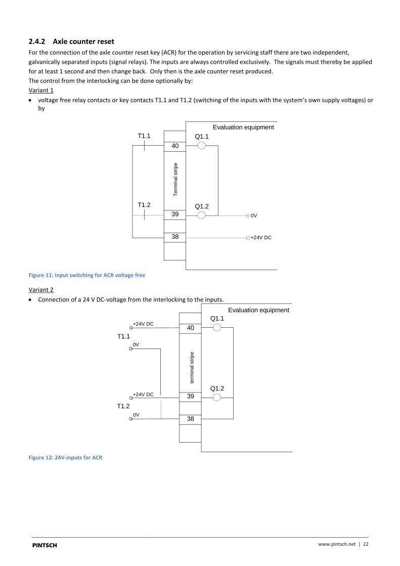
2.4.2 Axle counter reset
For the connection of the axle counter reset key (ACR) for the operation by servicing staff there are two independent,
galvanically separated inputs (signal relays). The inputs are always controlled exclusively. The signals must thereby be applied
for at least 1 second and then change back. Only then is the axle counter reset produced.
The control from the interlocking can be done optionally by:
Variant 1
voltage free relay contacts or key contacts T1.1 and T1.2 (switching of the inputs with the system’s own supply voltages) or by
Evaluation equipment
40
39
38
Te
rmin
al str
ipe
Q1.1
Q1.2
+24V DC
0V
T1.1
T1.2
Figure 11: Input switching for ACR voltage free
Variant 2
Connection of a 24 V DC-voltage from the interlocking to the inputs.
Evaluation equipment
40
39
38
term
ina
l str
ipe
Q1.1
Q1.2
+24V DC
+24V DC
0V
0V
T1.1
T1.2
Figure 12: 24V-inputs for ACR

www.pintsch.net | 23
3 Application conditions
www.pintsch.net | 24
3.1 External equipment
3.1.1 Electrical conditions
Electrical interference 250 Veff (continuous interface)
in the external plant (DSS): 1.6 kVeff (intermittent interface)
3,1 kV Shock
The DSS is resistant to defects caused by traction return currents, magnetic rail brakes, eddy current brakes and magnetised
wheelsets. The insensitivity to lightening flashes or overhead line short circuits is given to the required extent. The DSS can
withstand a test alternating voltage of 2 kV against earth or 1 kV between the systems. The DSS is watertight and dust tight
(protection class IP 67). Deposits of snow, ice, oil or dirt do not affect the ability of the DSS to operate.
EMC: Designed and tested according to EN 50121-4 (CENELEC) The test procedures to be used are the direct discharge, indirect discharge, burst, energy dense impulses and walky-talky test.
For the DSS it has already been shown that it was not affected by other cables laid parallel to it (e.g. telephone cables).
However, if heavy current cables of supply equipment, point motors, pump motors or similar are laid parallel over the complete
length to the DSS connection cable they should be kept at least 6 cm away.
3.1.2 Climatic conditions
Ambient temperature: +85°C to -40°C
Humidity: Water with occasional immersion (IP 67)
Air pressure: 700 to 1320 hPa (corresponds to 0 to 2200 m above sea level)
3.1.3 Mechanical conditions
Vibrations: 60g at a frequency band of 25-30 Hz Loading: < 200 kg in vertical direction

www.pintsch.net | 25
3.2 Internal equipment
3.2.1 Electrical conditions
Electrical interference: 250 Veff (continuous interference)
in the internal plant (assessment): 1.6 kVeff (intermittent interference)
2.3 kVShock (flash)
The air and creep paths in the internal equipment should be designed as specified in DIN VDE 0106 Part 101 with reinforced
insulation for degree of fouling 2 (DIN VDE 0110).
EMC: Designed and tested according to EN 50121-4 The test procedures to be used are the direct discharge, indirect discharge, burst, energy dense impulses and walky-talky-test.
Voltage supply: Interruption of over 1 ms, 10 times
(Buffer battery or with unbuffered at intervals of 2 s
operation the input voltage) Voltage reduction -20% over 20 min
3.2.2 Climatic conditions
Ambient temperature: +50°C to -25°C
Humidity: 10% to 100% relative humidity
Annual mean 75% relative air humidity
Dew formation possible
Air pressure: 700 to 1320 hPa (corresponds to 0 to 2200 m above sea level)
Mechanical conditions
Vibrations: 10 to 55 Hz, 5 g, 20 mmss
Shock: 10 g

www.schaltbaugroup.com
PINTSCH GmbH Hünxer Str. 149 46537 Dinslaken Germany
T +49 20 64 602-0 F +49 20 64 602-266
[email protected] www.pintsch.net