
Sensor Interface Conditioner For Distributed …granitesemi.com/SensorInterfaceConditioner.pdfSensor...
15
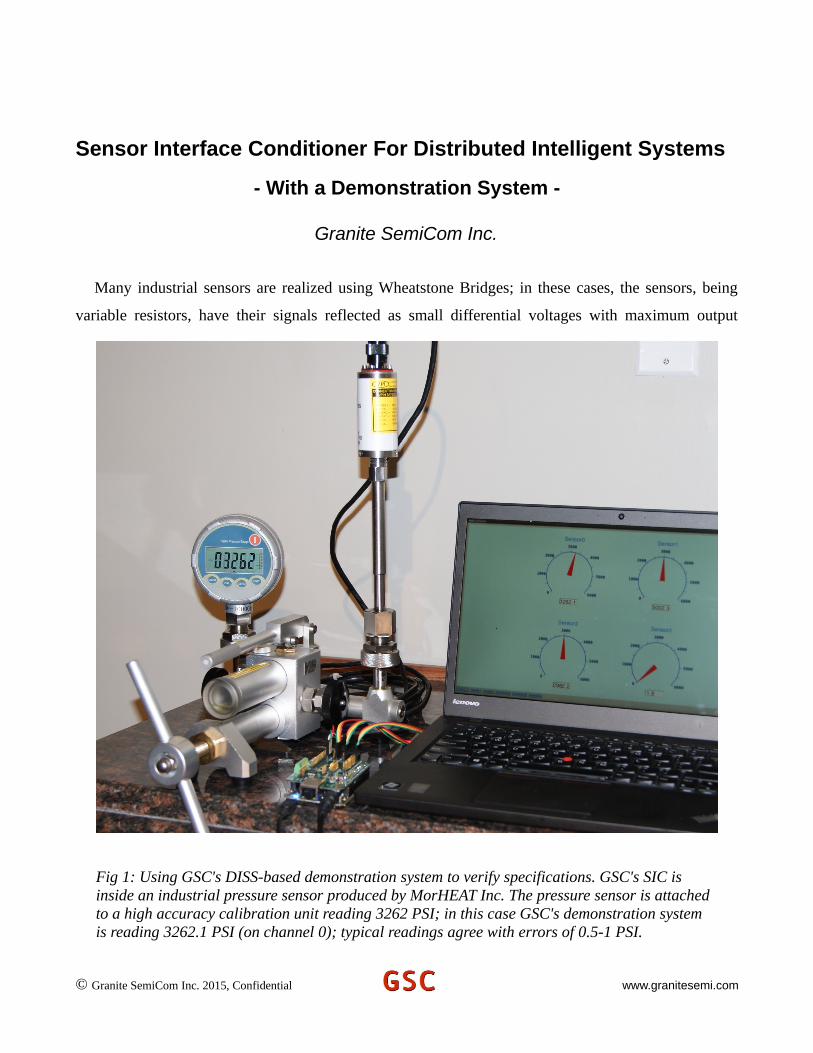
Sensor Interface Conditioner For Distributed Intelligent Systems - With a Demonstration System - Granite SemiCom Inc. Many industrial sensors are realized using Wheatstone Bridges; in these cases, the sensors, being variable resistors, have their signals reflected as small differential voltages with maximum output © Granite SemiCom Inc. 2015, Confidential www.granitesemi.com Fig 1: Using GSC's DISS-based demonstration system to verify specifications. GSC's SIC is inside an industrial pressure sensor produced by MorHEAT Inc. The pressure sensor is attached to a high accuracy calibration unit reading 3262 PSI; in this case GSC's demonstration system is reading 3262.1 PSI (on channel 0); typical readings agree with errors of 0.5-1 PSI.
Transcript of Sensor Interface Conditioner For Distributed …granitesemi.com/SensorInterfaceConditioner.pdfSensor...
Sensor Interface Conditioner For Distributed Intelligent Systems
- With a Demonstration System -
Granite SemiCom Inc.
Many industrial sensors are realized using Wheatstone Bridges; in these cases, the sensors, being
variable resistors, have their signals reflected as small differential voltages with maximum output
© Granite SemiCom Inc. 2015, Confidential www.granitesemi.com
Fig 1: Using GSC's DISS-based demonstration system to verify specifications. GSC's SIC is inside an industrial pressure sensor produced by MorHEAT Inc. The pressure sensor is attached to a high accuracy calibration unit reading 3262 PSI; in this case GSC's demonstration system is reading 3262.1 PSI (on channel 0); typical readings agree with errors of 0.5-1 PSI.
voltages in the range of 25-50mV. The function of a Sensor Interface Conditioner (SIC) is to amplify
and condition these signals so they can be communicated to an output device; often this means a
computer that might be a significant distance from the sensor. The SIC is usually close to the sensor,
and traditionally the communication to the output device would be done using the industry standard 4-
20mA 2-wire interface. Only recently, are SIC's becoming available where the communication to the
output device is done using digital signals and a serial interface. Granite SemiCom Inc. (GSC) has
developed a SIC with specifications close to the best in the industry, where the digital signals are
transmitted to the output device using an I2C digital serial link. Intended applications use an output
device that is either a digital controller or a small board computer. GSC has also developed a
Demonstration System based on Distributed Intelligent Sensor Systems (DISS's) that teaches how to
use the SIC's and to verify their excellent specifications, that can be used to program the SIC's using
either a Graphical User Interface (GUI) or a script from a file (or both), and that can also be used to for
Remote Control and Debug of DISS's from locations almost anywhere on earth; as long as an Internet
link exists.
© Granite SemiCom Inc. 2015, Confidential www.granitesemi.com
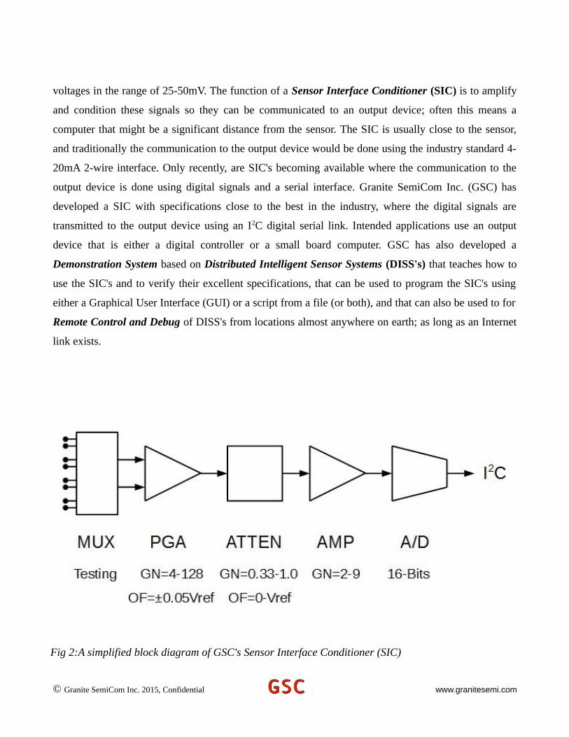
Fig 2:A simplified block diagram of GSC's Sensor Interface Conditioner (SIC)

Sensor Interface Conditioner
Fig 1 shows GSC's SIC being evaluated for use as the interface to an Industrial High-Pressure
Sensor produced by MorHEAT Inc. (www.morheat.com) for “Melt Pressure” applications; GSC''s SIC
is inside the sensor housing and connected to a smart computer board using the I2C interface; the
demonstration software all runs on the computer board but the higher levels can run on remote host
computers. In the Demonstration System, with all the GUI software running on the small computer
board, the output of the software is communicated to a host computer using a secure encrypted link
based on the SSH protocol with the -X option specified (that allows remote X-windows viewing). In
this picture, the SSH connection to the host computer is through a USB cable; alternatives that have
been developed are through 100Mbs Ethernet cables or wirelessly using WiFi. Any controller or smart
computer board that supports I2C can be connected to GSC's SIC; for the Demonstration System, the
controller is based on using the Beaglebone Black computer with a Controller Interface Board (CIB)
also developed by GSC and supplied with its Demonstration System. The CIB allows for 4 SIC's to be
interfaced with a single board; it also has an 8-bit GPIO parallel interface, temperature sensor,
programmable power supply, and supply voltage and temperature measurement feedback for robust
operation and remote debugging.
The GIC Sensor Interface Conditioner (SIC) is a high-accuracy highly reconfigurable interface that
includes self-debug capability allowing for remote debugging in the event of failure. A block diagram
of the SIC is shown in Fig. 2. A summary of its features are:
Sensor Interface Conditioner (SIC) Features:
• Connects directly to Wheatstone-bridge, no other electronics required.
• Connects to Cape Board using 4-wire digital I2C interface for both data and power.
• Highly accurate and linear with very low noise.
• Uses 16-bit A/D converter.
• Is digitally programmable in the field to accommodate a wide range of gains, and offsets; one design is widely applicable to many applications minimizing inventory costs
• Has three gain calibrations: front end programmable gain amplifier (4.0 to 128.0), output amplifier (2.0 to 9.0) and high-resolution (16 bits) attenuator (0.333 to 1.0). In addition, the gainsign can be inverted.
© Granite SemiCom Inc. 2015, Confidential www.granitesemi.com
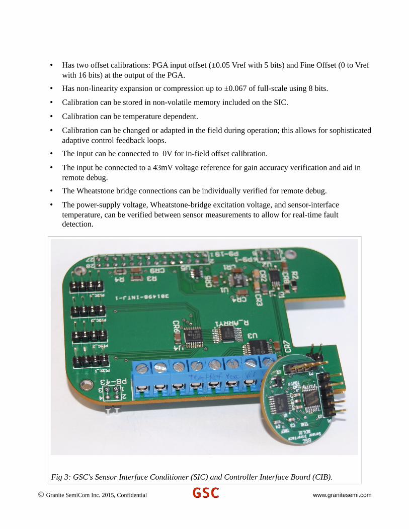
• Has two offset calibrations: PGA input offset (±0.05 Vref with 5 bits) and Fine Offset (0 to Vref with 16 bits) at the output of the PGA.
• Has non-linearity expansion or compression up to ±0.067 of full-scale using 8 bits.
• Calibration can be stored in non-volatile memory included on the SIC.
• Calibration can be temperature dependent.
• Calibration can be changed or adapted in the field during operation; this allows for sophisticatedadaptive control feedback loops.
• The input can be connected to 0V for in-field offset calibration.
• The input be connected to a 43mV voltage reference for gain accuracy verification and aid in remote debug.
• The Wheatstone bridge connections can be individually verified for remote debug.
• The power-supply voltage, Wheatstone-bridge excitation voltage, and sensor-interface temperature, can be verified between sensor measurements to allow for real-time fault detection.
© Granite SemiCom Inc. 2015, Confidential www.granitesemi.com
Fig 3: GSC's Sensor Interface Conditioner (SIC) and Controller Interface Board (CIB).

Pictures of the SIC and GIC's Sensor Interface Cape board are shown in Fig. 3. This round version of
the SIC is intended to be encapsulated in an industrial sensor using epoxy; alternative square versions
have holes for mounting to a chassis, a box, or a PCB.
Sensor Controller Interface Board (CIB)
A Sensor Controller Interface Board (CIB) has also been developed, and is supplied as part of GSC's
Demonstration System. The Demonstration System helps teach how to program the SIC's, and to
demonstrate their functionality and accuracy. GIC's Controller Interface Board (often called a “Cape” )
connects to the Beaglebone Black (BBB) computer board available from Sparkfun
(www.sparkfun.com) and other distributors. The BBB is relatively fast, has lots of memory, both RAM
and non-volatile (a 4Gbyte eMMMC), enables connecting to the Internet for remote control and
communication straight-forward, and with its Debian operating system, provides a wealth of open-
source software that greatly minimizes development time. For example, secure encrypted
communication to the Internet using SSH is used. However, using the BBB is just one alternative; the
SIC's can alternatively be connected to any controller that has an I2C interface, and GSC with its
Design Services business model readily supports program development for connecting to alternative
controllers. GSC's Demonstration System includes a preprogrammed BBB and Cape Interface Board to
simplify users getting started; the Demonstration System also includes 4 SIC's, and a Sensor Emulator
Board including a pressure sensor.
The Controller Interface Board (CIB) allows four SIC's to be connected to the CIB and used at the
same time, even when they have identical Device addresses. Indeed, each of the four I2C channels can
also be connected to multiple Devices, but all Devices on a single channel must have unique addresses.
The number of channels can be expanded on custom boards in response to a customer's request.
The CIB has a programmable power supply voltage, has an 8 pin GPIO, and has output voltage
verification and CIB temperature verification to support remote verification of correct functionality. A
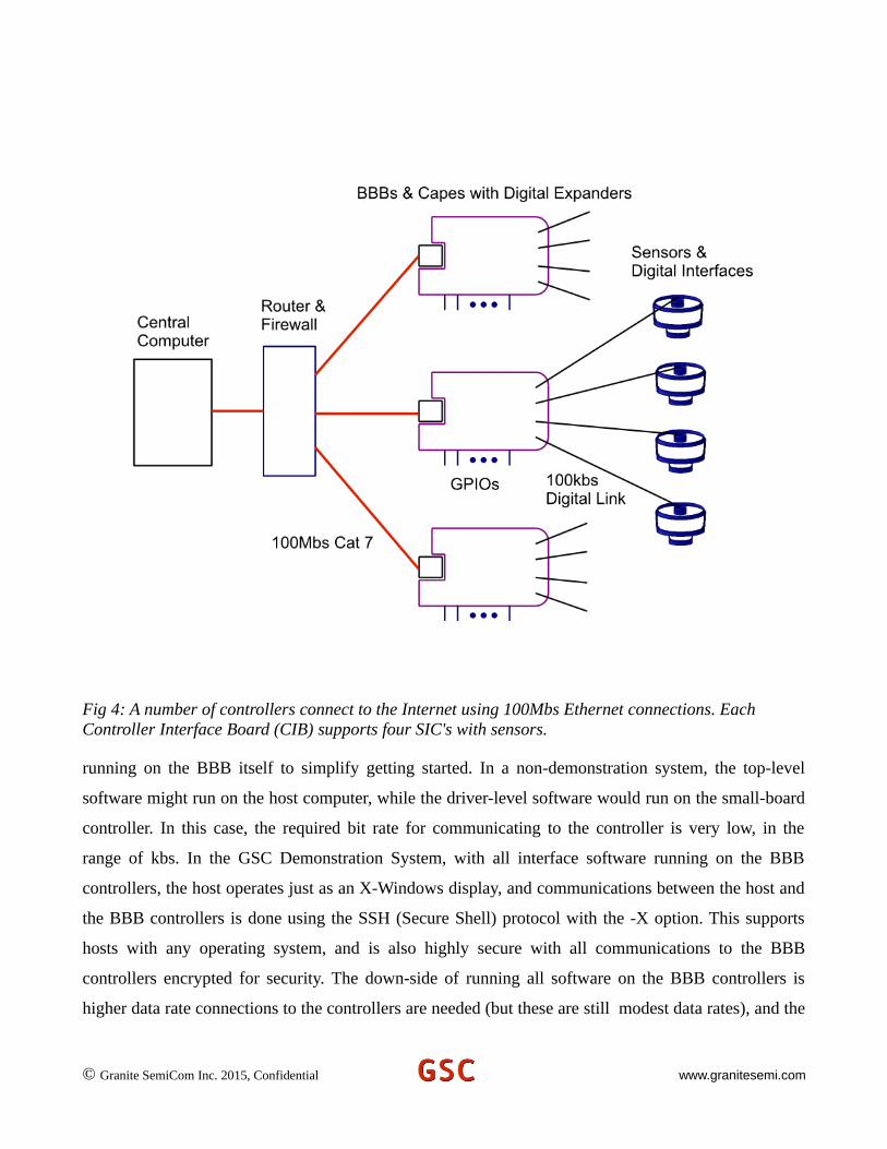
typical connection for the Demonstration System is shown in Fig. 4, where a number of small computer
controllers are connected using Ethernet Cat 7 cables to a router. Alternative connections for the BBB
controllers are through USB cables, or wirelessly using either a WiFi dongle or a Bluetooth dongle
plugged into the BBB's USB port. The GSC Demonstration System comes with software that is all
© Granite SemiCom Inc. 2015, Confidential www.granitesemi.com
running on the BBB itself to simplify getting started. In a non-demonstration system, the top-level
software might run on the host computer, while the driver-level software would run on the small-board
controller. In this case, the required bit rate for communicating to the controller is very low, in the
range of kbs. In the GSC Demonstration System, with all interface software running on the BBB
controllers, the host operates just as an X-Windows display, and communications between the host and
the BBB controllers is done using the SSH (Secure Shell) protocol with the -X option. This supports
hosts with any operating system, and is also highly secure with all communications to the BBB
controllers encrypted for security. The down-side of running all software on the BBB controllers is
higher data rate connections to the controllers are needed (but these are still modest data rates), and the
© Granite SemiCom Inc. 2015, Confidential www.granitesemi.com
Fig 4: A number of controllers connect to the Internet using 100Mbs Ethernet connections. Each Controller Interface Board (CIB) supports four SIC's with sensors.
controllers need to have more capabilities (which the BBB controllers do have). In applications where
less powerful controllers are used, the top level software would always run on the host computer.
Features of the BBB controller with GSC's Controller Interface Board include:
© Granite SemiCom Inc. 2015, Confidential www.granitesemi.com
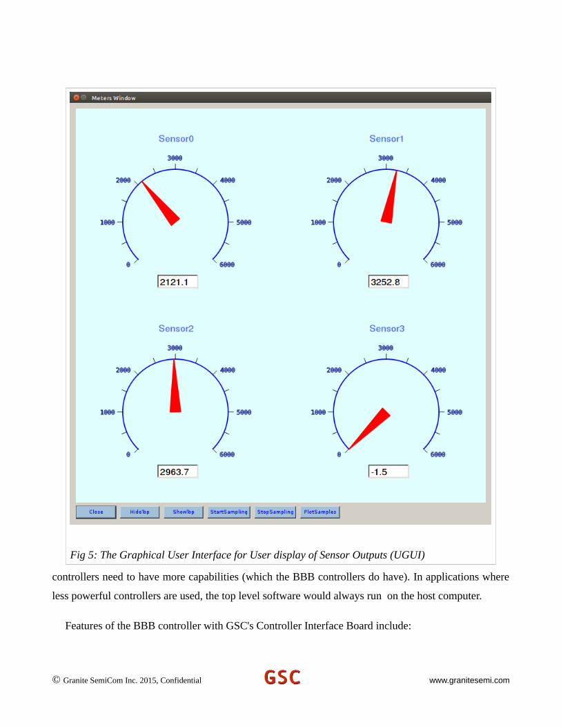
Fig 5: The Graphical User Interface for User display of Sensor Outputs (UGUI)
Controller Interface Board Features:
• 4 individually addressable I2C outputs for Devices having identical addresses; each of the 4 outputs can connect to multiple I2C slaves as long as their Device addresses are different.
• 8 GPIO digital signals; each signal can be programmed as input or output; each signal can be individually read or written, or all 8 can be read or written simultaneously (even with mixed input and outputs). Each signal can optionally have a pull-up resistor connected, and each signalprogrammed as an input can have its signal optionally inverted. The GPIO connector has screw-on connections.
© Granite SemiCom Inc. 2015, Confidential www.granitesemi.com
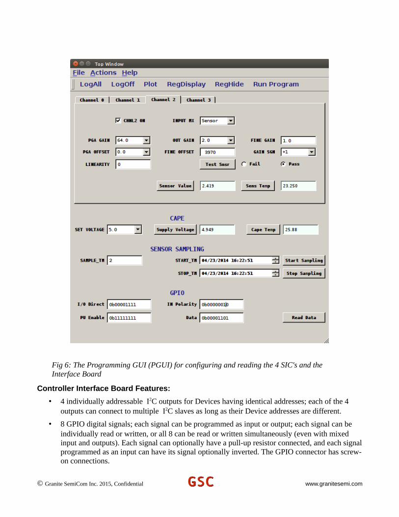
Fig 6: The Programming GUI (PGUI) for configuring and reading the 4 SIC's and the Interface Board
• The CIB power-supply voltage can be programmed between 2.5V and 5.0V.
• The CIB power-supply voltage can be continuously monitored.
• The CIB temperature can be continuously monitored.
• The CIB has an EEPROM for non-volatile data logging; this allows for “Black Box” functionality or other user-defined purposes.
• BBB controllers appears as “nodes” on a local Internet, and each controller includes an SSL server for encrypted communications, firewall security, privileged user only access, local logging capability, etc. The Internet address of each node can be hard configured, or automatically obtained using DHCP, and VPN and other higher-level Internet protocols connections are supported.
SIC Software Interface
The software interface to the SIC's supports interfacing using either Graphical User Interfaces
(GUI's), using a script programming interface where the programs are previously stored in files, or
optionally using both approaches. Detailed help on software interfaces is included in the help files of
the GUI's supplied with the Demonstration System.
The software approach recommended by GSC is to separate the details into three different
Abstraction Levels on a Need-to-Know basis. The recommended levels are: User Level, Programming
Level, and Driver Level. For the GSC Demonstration System, the User Level is simply a GUI showing
4 meters and digital readouts, one for each of the 4 sensors attached to the CIB (Cape Interface Board).
In addition, the User GUI has buttons to start and stop sampling, and to display the GUI for the next
lower level of abstraction, namely the Programming GUI (PGUI). The lowest level of abstraction, that
can be displayed using the PGUI, is the Device Register Interface GUI (DGUI); this GUI is used for
remote debug, but is not needed or intended when configuring, programming, or interfacing with, the
SIC's.
User GUI
The User Interface GUI (UGUI) supplied with GSC's Demonstration System is shown in Fig. 5.
This interface takes the sensor voltage readings from the Program GUI (PGUI), and converts them to
appropriate values for displaying on the meters. The conversion normally involves subtracting an offset
value, and then multiplying by a unit-conversion constant from the PGUI's voltage units to whatever
© Granite SemiCom Inc. 2015, Confidential www.granitesemi.com
units are appropriate for display depending on the particular application. The offset and gain-
conversion constants come from a configuration file and can be easily changed by editing the
configuration file or alternatively using a start-up script. The default at start-up (easily changed), is
only the UGUI is visible; the PGUI can be made visible by clicking the “ShowTop” button, and later
hidden again by clicking the “HideTop” button. Continuous sensor sampling is enabled, by default, at
start-up. This default is also easily changed. Continuous sampling can be stopped by clicking
“StopSampling”, and re-started by clicking “StartSampling”. After sampling has been stopped, it is
possible to plot the results by clicking “PlotSamples”. The plots are easily zoomed (using the mouse
wheel and right-click dragging) and panned (left-click dragging). Each time sampling is stopped and
restarted, previous samples are automatically saved with a unique file name including the time and date
of saving. Finally, the Sensor-Interface Demonstration Program can be halted by clicking the “Quit”
button.
Programming GUI
Configuring and changing the Sensor Interface System is done at the Programming Level. This can
achieved by either using the Programming GUI (PGUI), or by using commands from a script file. If a
file called “.sinit” exists in the main directory the software resides in, then it is automatically run at
start-up. Also, at any time, script commands from a file can be run using a menu command (“File->Run
Program”). The script commands are well documented in the Help menu of the PGUI shown in Fig. 6
The layout and defaults of this GUI, including initial default values, has been largely automated
based on a single configuration file (the same is true for the lowest-level DGUI). This allows the GUI
to be easily customized for different applications, minimizing costs given a Design Services business
model.
The entry elements of the PGUI are mostly Line Edits, Combo Boxes, Check Boxes, or Time Edits.
In addition, commands can be initiated using buttons and menu choices. The PGUI does not directly
interact with the SIC's; rather it sends commands to the lowest level Device GUI (DGUI), that will be
described shortly. The PGUI configures up to four SIC's, and also the Cape Interface Board (CIB). It
can also be used to start and stop continuous sampling, or to schedule future sampling. Other control
functions include enabling or disabling command logging (for debug purposes), and to display or hide
© Granite SemiCom Inc. 2015, Confidential www.granitesemi.com

the low-level Device GUI (DGUI). The approach of having an intermediate LEVEL PGUI is to hide
low-level details from the programmer to make programming easier. These details include which
Device Register, or Register Bits, configure which function. At the Programming Level, the interaction
is from a functional point of view, and device-level knowledge of how to go from functional commands
to programming register bits is not necessary; functional programmers do not need to be hardware
engineers as the hardware interface has been hidden using abstraction. The low-level details are looked
after by the Device Driver Level Interface. The PGUI also configures the CIB supply voltage, reads the
same, reads the CIB temperature, configures, sets and reads the 8-bit GPIO, and has an EEPROM
available for any desired purpose.
Driver GUI
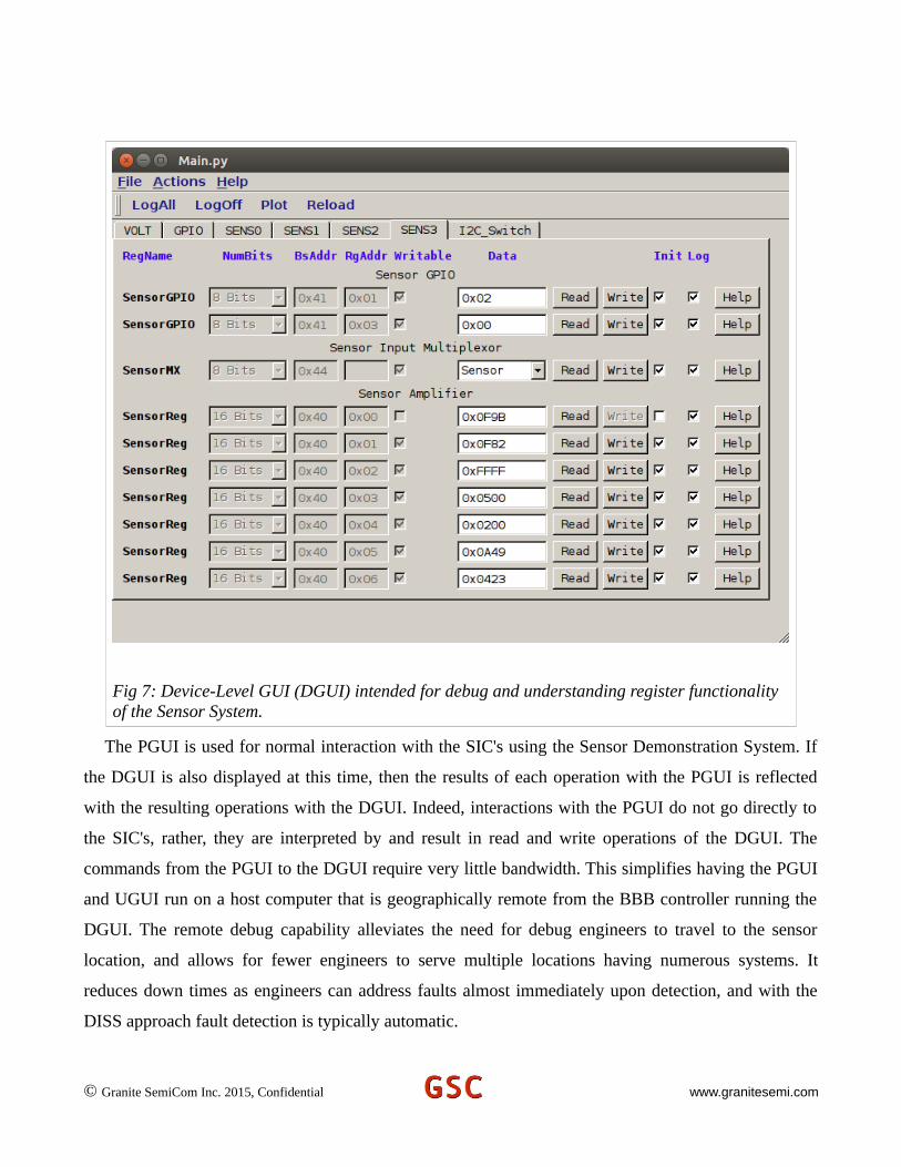
The GUI for interaction at the Driver Level (DGUI) is shown in Fig 7. Many sensor system devices can
be interacted with simply by reading and writing registers; the DGUI has been developed for these
cases. Each line in the DGUI represents a register. Registers have device and internal addresses, default
values at start-up, can be written and read, and can have their read and write operations logged. The
DGUI has been designed to accommodate these operations. The first item displays the register name.
The Line Edits that appear gray can not be changed, their values come from a configuration file and
describe parameters required by the I2C communication channel. The first Line Edit (the second item)
displays whether the register is 8 bits wide or 16 bits wide. The second Line Edit displays the address
of the register in hex notation for an 8 bit value. The third Line Edit displays the register address
internal to a Device as each Device often has multiple internal registers. The fourth widget is a Check
Box and when checked indicates the register is an Input only type register. The fifth item (often called a
widget) can be either a Line Edit or a Combo Box widget; this widget displays the contents of the
Device register and is called the Contents Widget. Whenever the fifth widget is changed, the register is
automatically written into and then re-read to verify its contents are correct. The sixth and the seventh
items are buttons; the Read button causes the Device internal register to be read and to have the
Contents Widget (that is the fifth widget) updated with the Device's register value; the Write button
takes the current value of the Contents Widget and writes that value into the Device internal register.
The next two widgets are Check Boxes; the first one is checked if the register needs to be initialized at
start-up (read-only registers are not initialized), and the second Check Box indicates whether logging of
© Granite SemiCom Inc. 2015, Confidential www.granitesemi.com

register reads and writes is taking place. The last widget is a Help button; when clicked, this button
pops up a window that describes the functionality of the particular register and how its contents affect
the operation of the Device; since the help is stored with Demonstration System appropriate for the
system's supplied Devices, the help is guaranteed to be the correct version for the supplied Device
versions; in addition, during debug, it is not necessary to search (perhaps on-line) for the proper
documentation; the help and documentation is always readily available at the click of a button.
The logging capability of the Three-Level-Abstraction approach is valuable in debugging (often
remotely) in the event something goes wrong. When logging is enabled for a particular register (the
default is to enable logging for all registers (this is easily changed with the configuration file), then
every read and write operation is logged into a file, with the before and after contents of the register,
and the exact time of the operation. At start-up, if a log file exists from a previous run, it is
automatically saved with a file name that includes the time and date of saving. The files are saved into
non-volatile memory; they can be saved into the eMMC memory or optionally into a micro-SD card so
the contents can be easily retrieved even if the BBB board fails. Since the BBB controller boards have
plenty of memory (and SD cards of up to 32 Gbytes can be used), having enough memory for logging
all operations with long run times is not an issue.
© Granite SemiCom Inc. 2015, Confidential www.granitesemi.com
The PGUI is used for normal interaction with the SIC's using the Sensor Demonstration System. If
the DGUI is also displayed at this time, then the results of each operation with the PGUI is reflected
with the resulting operations with the DGUI. Indeed, interactions with the PGUI do not go directly to
the SIC's, rather, they are interpreted by and result in read and write operations of the DGUI. The
commands from the PGUI to the DGUI require very little bandwidth. This simplifies having the PGUI
and UGUI run on a host computer that is geographically remote from the BBB controller running the
DGUI. The remote debug capability alleviates the need for debug engineers to travel to the sensor
location, and allows for fewer engineers to serve multiple locations having numerous systems. It
reduces down times as engineers can address faults almost immediately upon detection, and with the
DISS approach fault detection is typically automatic.
© Granite SemiCom Inc. 2015, Confidential www.granitesemi.com
Fig 7: Device-Level GUI (DGUI) intended for debug and understanding register functionality of the Sensor System.
Summary
A high-accuracy Sensor Interface Conditioner (SIC) has been developed. It is intended to be
connected to a controller or small-board computer with an I2C digital serial link. A Sensor
Demonstration System is being offered that allows 4 sensors with SIC's to be connected to a small
Beaglebone Black computer board. The system demonstrates use of the SIC's, has extensive built-in
self test, and data logging, and demonstrates a new software approach for interacting with Distributed
Intelligent Sensor Systems (DISS's). The software interface of the Sensor Development System is
based on Three-Level-Abstraction, each level having its own Graphical User Interface (GUI); these are:
the User Interface, the Programming Interface, and the Driver Interface. This simplifies interactions
with and programming of the SIC's, yet still allows complete control and remote debug. In addition, the
SIC's can be interacted with using scripts from files. Together, the GUI and program-based interaction
give flexibility and fast development of systems based on the SIC's with extensive built-in test and
remote control and debugging capabilities. Faults are detected and can be addressed almost
immediately using fewer engineers in a central location; Time and Trust are simultaneously optimized.
Granite SemiCom [email protected] 640-2626
www.granitesemi.com
© Granite SemiCom Inc. 2015, Confidential www.granitesemi.com

Short Biography of the President
Kenneth W. Martin was a Professor at UCLA from1980 to 1991. He attained tenure (Associate Professor)in 1982, and became a Full Professor in 1987. In 1985,he founded the Integrated Circuits and SystemsLaboratory (ICSL) and Major Field at UCLA, whichbecame the incubator of many high-tech companies inSouthern California, including Broadcom. In 1991,Professor Martin returned to the University of Toronto toaccept a position as an Endowed Professor, which heheld until 2008, when he became an Adjunct Professor.While at the University of Toronto, he co-authored (withDavid Johns) Analog Integrated Circuit Design, apopular graduate-level textbook. A second edition waspublished in 2011, with Prof. Tony Chan-Carusonejoining as an additional co-author. He has also co-authored numerous other books, chapters, and well over100 papers.
Professor Martin has received many awards: He wasselected by the IEEE Circuits and Systems Society forthe Outstanding Young Engineer Award, which waspresented at the IEEE Centennial "Keys to the Future" Program in 1984. Dr. Martin was granted the NSF Presidential Young Investigator's Award, which continued from 1985 to 1990. He was a co-recipient of the Beatrice Winner Award at the 1993 ISSCC and a co-recipient of the 1999 IEEE Darlington Best-Paper Award for the paper “Transactions on the Circuits and Systems.” He was also awarded the 1999 CAS Golden Jubilee Medal of the IEEE Circuits and Systems Society. Professor Martin is a Fellow of the IEEE (FIEEE).
Dr. Martin founded (along with David Johns) Snowbush Microelectronics in 1988; the enterprise grew organically from one employee to a highly profitable company with 50 employees, including a Mexican Design Center, in its ten year existence. Snowbush was acquired by Gennum Corp. in 2007; Dr. Martin served as Chief Technical Officer at Gennum Corp. for one year after the acquisition. Snowbush is now a highly successful division of SemTech Corp.
Professor Martin is currently President of Granite SemiCom Inc., a Design Services Company.
© Granite SemiCom Inc. 2015, Confidential www.granitesemi.com