Sensor Development for the iMote2 Smart Sensor...
21
Sensor Development for the iMote2 Smart Sensor Platform Jennifer Rice March 7, 2008 SPIE Smart Structures/NDE 2008
Transcript of Sensor Development for the iMote2 Smart Sensor...
Sensor Development for the iMote2 Smart Sensor Platform
Jennifer RiceMarch 7, 2008
SPIE Smart Structures/NDE 2008
Jennifer RiceSPIE Smart Structures/NDE
March 13, 2008
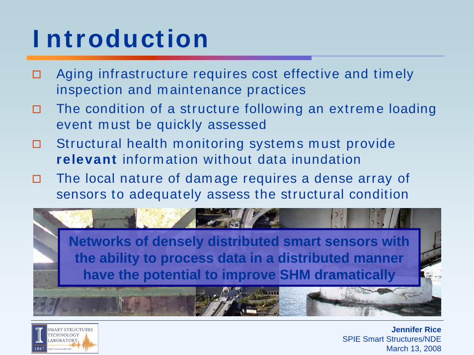
IntroductionAging infrastructure requires cost effective and timely inspection and maintenance practicesThe condition of a structure following an extreme loading event must be quickly assessedStructural health monitoring systems must provide relevant information without data inundationThe local nature of damage requires a dense array of sensors to adequately assess the structural condition
Networks of densely distributed smart sensors with the ability to process data in a distributed manner
have the potential to improve SHM dramatically

Jennifer RiceSPIE Smart Structures/NDE
March 13, 2008
Advances in microprocessor and MEMS technology have led to the potential for highly adaptable, densely distributed smart sensor networksFeatures of a smart sensor:
Smart Sensors
Wireless Radio
Data StorageProcessor
Wireless sensorsWireless sensors Smart SensorsSmart SensorsWired sensors Wired sensors
Self-powered
Low Cost
ScalabilityScalability
Utilize the computational power of the smart sensor nodes to realize distributed computingLimit the amount of raw data that is shared amongst sensors
The evolution research on sensor networks for structural health monitoring

Jennifer RiceSPIE Smart Structures/NDE
March 13, 2008
Intel’s iMote2Second generation of Intel moteGeared toward higher bit-rate applicationsLow-power 32-bit XScale processor (PXA271)Scalable processor speed to improve power consumption802.15.4 radio (ChipCon 2420)Data storage
256KB SRAM32MB External SDRAM32MB Flash
Mica2 iMote2
Microprocessor ATmega128L XScalePXA271
Clock speed (MHz) 7.373 13-416
Active Power (mW) 24 @ 3V44 @ 13 MHz,
570 @ 416 MHz
Data rate (kbps) 38.4 250
Program flash (bytes) 128 K 32 M
RAM (bytes) 4 K 256 K +32 M external
Nonvolatile storage (bytes)
512 K 32 M(Program flash)
Size (mm) 58 x 32 x 7 48 x 36 x 7
Jennifer RiceSPIE Smart Structures/NDE
March 13, 2008
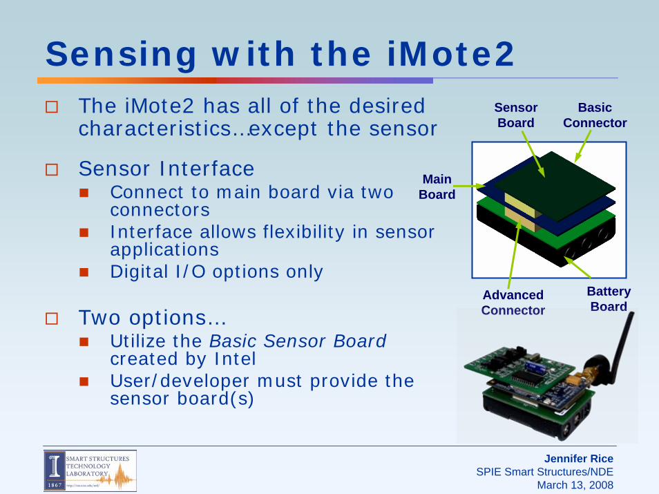
Sensing with the iMote2The iMote2 has all of the desired characteristics…except the sensor
Sensor InterfaceConnect to main board via two connectorsInterface allows flexibility in sensor applicationsDigital I/O options only
Two options…Utilize the Basic Sensor Board created by IntelUser/developer must provide the sensor board(s)
Advanced Connector
Basic Connector
Main Board
Sensor Board
Battery Board
Jennifer RiceSPIE Smart Structures/NDE
March 13, 2008
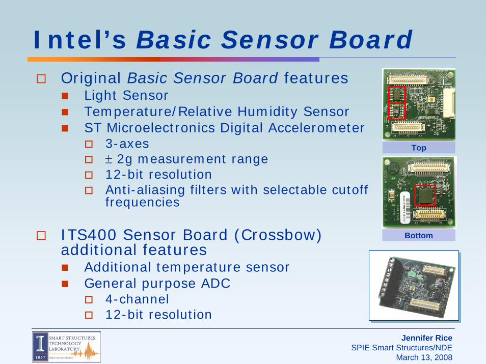
Intel’s Basic Sensor BoardOriginal Basic Sensor Board features
Light SensorTemperature/Relative Humidity SensorST Microelectronics Digital Accelerometer
3-axes± 2g measurement range12-bit resolutionAnti-aliasing filters with selectable cutoff frequencies
ITS400 Sensor Board (Crossbow) additional features
Additional temperature sensorGeneral purpose ADC
4-channel12-bit resolution
Top
Bottom
Jennifer RiceSPIE Smart Structures/NDE
March 13, 2008
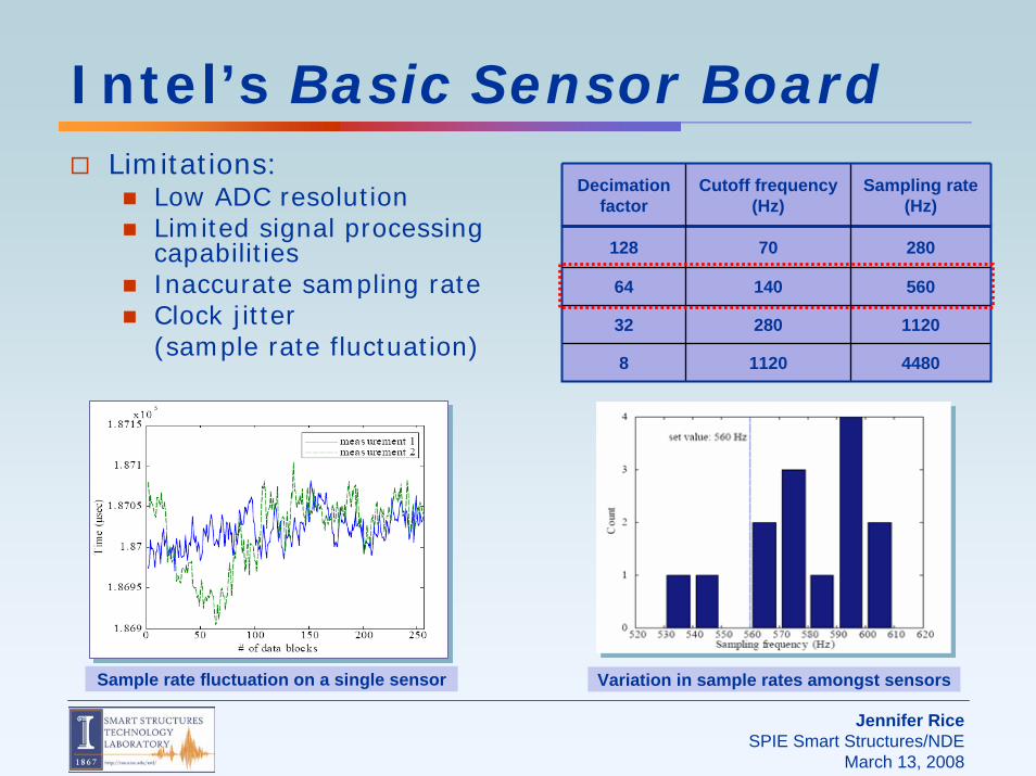
Sample rate fluctuation on a single sensor
Intel’s Basic Sensor BoardLimitations:
Low ADC resolutionLimited signal processing capabilitiesInaccurate sampling rateClock jitter (sample rate fluctuation)
Variation in sample rates amongst sensors
Decimation factor
Cutoff frequency(Hz)
Sampling rate (Hz)
128 70 280
64 140 560
32 280 1120
8 1120 4480
Jennifer RiceSPIE Smart Structures/NDE
March 13, 2008
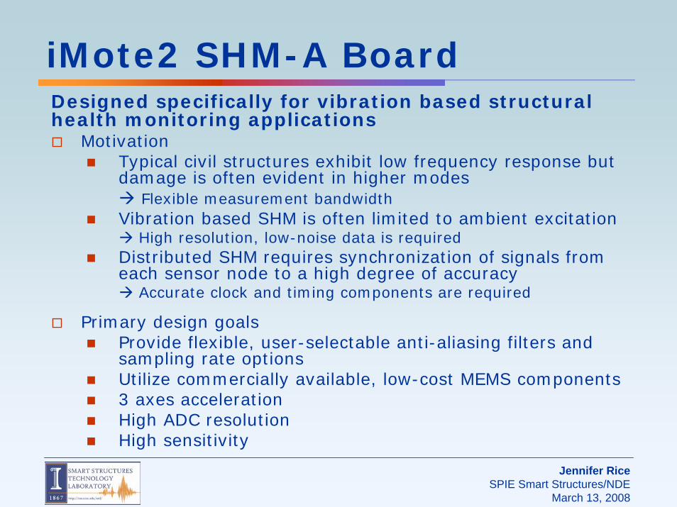
iMote2 SHM-A BoardDesigned specifically for vibration based structural health monitoring applications
MotivationTypical civil structures exhibit low frequency response but damage is often evident in higher modes
Flexible measurement bandwidthVibration based SHM is often limited to ambient excitation
High resolution, low-noise data is requiredDistributed SHM requires synchronization of signals from each sensor node to a high degree of accuracy
Accurate clock and timing components are required
Primary design goalsProvide flexible, user-selectable anti-aliasing filters and sampling rate optionsUtilize commercially available, low-cost MEMS components3 axes accelerationHigh ADC resolutionHigh sensitivity
Jennifer RiceSPIE Smart Structures/NDE
March 13, 2008
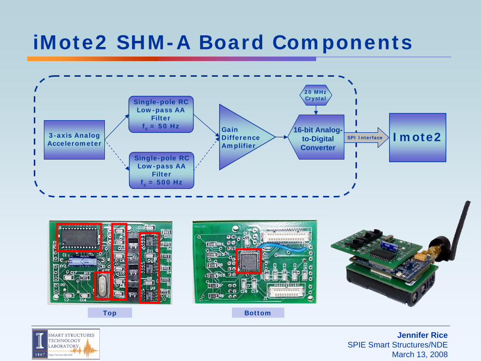
3-axis Analog Accelerometer
Single-pole RC Low-pass AA
Filter fc = 500 Hz
Single-pole RC Low-pass AA
Filter fc = 50 Hz Gain
Difference Amplifier
16-bit Analog-to-Digital Converter
20 MHz Crystal
iMote2 SHM-A Board Components
SPI Interface Imote2
Top Bottom

Jennifer RiceSPIE Smart Structures/NDE
March 13, 2008
iMote2 SHM-A Board Components
ST Microelectronics Analog Accelerometer3-axes acceleration0.66 mV/g resolutionLow-powerModerate noise (50μg/√Hz)Cost: ~$12 per chip
Design limitationsHigh output impedance (110 kΩ)High margin or error in output resistor (±20%)
Jennifer RiceSPIE Smart Structures/NDE
March 13, 2008
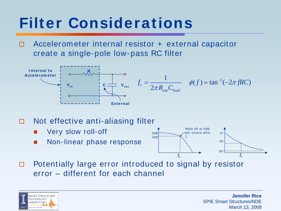
Filter ConsiderationsAccelerometer internal resistor + external capacitor create a single-pole low-pass RC filter
Not effective anti-aliasing filterVery slow roll-offNon-linear phase response
Potentially large error introduced to signal by resistor error – different for each channel
Vin Vout
R
C
fc
0dB3dB
Rolls off at 6dB per octave after fc
fc
0°
45°
90°
12c
out load
fR Cπ
=
Internal to Accelerometer
External
( )fφ = 1tan ( 2 )fRCπ− −

Jennifer RiceSPIE Smart Structures/NDE
March 13, 2008
Filter ConsiderationsCapacitor chosen sets the “cut-off”Consider three potential cut-off frequencies: 50 Hz, 500 Hz, and 1500 Hz (maximum allowed)
Phase mismatch occurs when channels have different values of output resistance (due to resistor error)To avoid potential phase mismatch and signal distortion, use the highest possible cut-off frequencyAddress aliasing in another way…
20 40 60 80 10080
60
40
20
0
20
fc = 50 Hzfc = 500 Hzfc = 1500 Hz
fc = 50 Hzfc = 500 Hzfc = 1500 Hz
Phase
f (Hz)
Deg
rees
20 40 60 80 1008
6
4
2
0
2
fc = 50 Hzfc = 500 Hzfc = 1500 Hz
fc = 50 Hzfc = 500 Hzfc = 1500 Hz
Filter Gain
f (Hz)
dB
20 40 60 80 1000
3
6
9
12Maximum Phase Mismatch
f (Hz)
Phas
e D
iffer
ence
(deg
)
fc = 50 Hzfc = 500 Hzfc = 1500 Hz
fc = 50 Hzfc = 500 Hzfc = 1500 Hz

Jennifer RiceSPIE Smart Structures/NDE
March 13, 2008
Digital Signal Processing
Flexible signal processingUser-selectable anti-aliasing filters, sampling frequencyOversampling-filtering-decimation provides sharp roll-off and linear phase responseSimilar to PC-based analyzers
Quickfilter Programmable Signal Conditioner
4-channels, single- or double-ended16-bit analog-digital-converter (ADC)Programmable gainsBuilt-in anti-aliasing filtersIndividually programmable digital FIR filters Digital SPI outputCost: ~$18 per chip

Jennifer RiceSPIE Smart Structures/NDE
March 13, 2008
QuickfilterBlock diagram of QF4A512
Oversampling-filtering-decimation serves two purposesIncreases resolution by reducing quantization noiseIn conjunction with simple analog anti-aliasing filters, produces un-aliased signal
PGA
AA Filter
3rd Order Besselfc = 500kHz
12-bit ADC
fs1 = 12.5MHz
Cascaded Integrator-Comb
(CIC) Filter/Decimator
Cascaded Integrator-
Halfband (CIH) Filter/Decimator
FIR Filter
User Defined
Digitized with high
oversampling rate
Filtered and decimated to fs2*4
Sinc filter Amplitude droop
Linear phase
Filtered and decimated to fs2
Compensates for CIC droop in
frequency domain
Maintains linear phase
Many filter designs available
Designed with QF software
Analog anti-aliasing filter
Gain amplifier
x2, x4, x8
Jennifer RiceSPIE Smart Structures/NDE
March 13, 2008
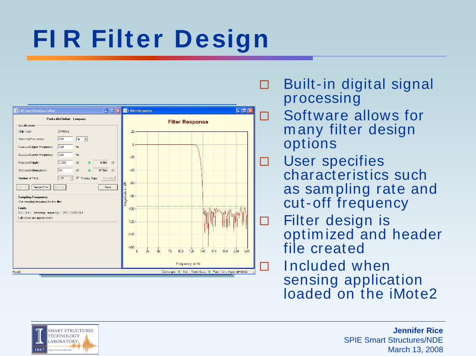
FIR Filter Design
Built-in digital signal processingSoftware allows for many filter design optionsUser specifies characteristics such as sampling rate and cut-off frequencyFilter design is optimized and header file createdIncluded when sensing application loaded on the iMote2
Jennifer RiceSPIE Smart Structures/NDE
March 13, 2008
SoftwareTinyOS is the operating system for many smart sensors including the iMote2
Small memory footprintPower efficientLarge user community
Driver was developed in TinyOS to control the functions of the ADC
Allocate memoryLoad FIR filter coefficientsSet sampling rateDo timestampingWrite data
Jennifer RiceSPIE Smart Structures/NDE
March 13, 2008
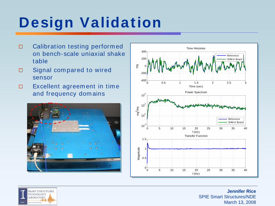
Design ValidationCalibration testing performed on bench-scale uniaxial shake tableSignal compared to wired sensorExcellent agreement in time and frequency domains
0 5 10 15 20 25 30 35 4010
-2
100
102
104
f (Hz)
mg2 /H
z
Power Spectrum
ReferenceSHM-A Board
0 0.5 1 1.5 2 2.5 3-400
-200
0
200
400
Time (sec)
mg
Time Histories
ReferenceSHM-A Board
0 5 10 15 20 25 30 35 400
0.5
1
1.5Transfer Function
Mag
nitu
de
f (Hz)

Jennifer RiceSPIE Smart Structures/NDE
March 13, 2008
Clock AccuracySampling rate accuracy estimation:
Sample rate set to 1000.32Hz (dt = 9.997e-04sec)Record timestamp from processor every 10th sampleSubtract consecutive timestamps and divide by ten to get average timestep over ten data points
Performance may be better than measured because timestamping itself may interfere with hardware timing
Measured sampling rate:
1000.44Hz (0.012% error)
Standard deviation of sample rate fluctuation:
0.11μs (0.011% error)0 100 200 300 400 500 600 700 800 900 10009.991
9.992
9.993
9.994
9.995
9.996
9.997
9.998
9.999
10.000
Timestamp Count
mse
cμs
ecμs
ec
Jennifer RiceSPIE Smart Structures/NDE
March 13, 2008
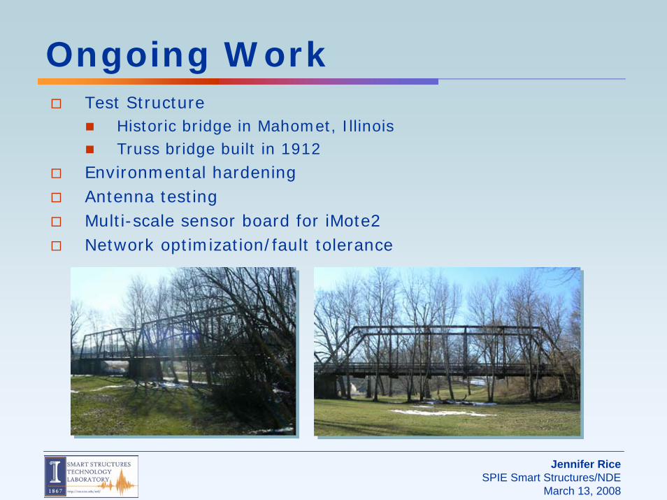
Ongoing WorkTest Structure
Historic bridge in Mahomet, IllinoisTruss bridge built in 1912
Environmental hardeningAntenna testingMulti-scale sensor board for iMote2Network optimization/fault tolerance

Jennifer RiceSPIE Smart Structures/NDE
March 13, 2008
ConclusionSmart Sensors, which incorporate wireless sensing with computational capability, allow for distributed SHM scenarios
The iMote2 provides data storage and computational capability required for SHM applications
A versatile accelerometer board has been designed for vibration-based SHM applications

Jennifer RiceSPIE Smart Structures/NDE
March 13, 2008
Acknowledgement
This work is sponsored in part by the National Science Foundation, Dr. Shih-Chi Liu, program manager
Additional support was provided by the Vodafone Graduate Fellowship program