Sensor Based E-Bike for College Campus
7
International Journal of Scientific and Research Publications, Volume 6, Issue 4, April 2016 531 ISSN 2250-3153 www.ijsrp.org Sensor Based E-Bike for College Campus Ravi Teja Ch.v, Ch.Pujitha, S.Gayatri, V.Jalander, Ch.Kavitha Department of Electronics and Communication Engineering, Anurag college of engineering, Hyderabad,Telangana,India. Abstract- Present day skateboards and bikes are truly engineering marvels; nevertheless they have already been so refined that they are quite simplistic by today’s high technology standards. Rapidly advancing technologies in many sectors including potential E-bikes are classed according to the power that their electric motor can deliver and the control system, i.e, when and how the power from the motor is applied. As such, the classification of these e-bikes varies greatly across countries. The classification of e-bikes is mainly decided by whether the e- bike’s motor assists the rider using a pedal –assist system or by a power-on-demand one. The existing systems are the electric powered manually balanced wheeled vehicles via the means of the electric motors. But for most of the users balancing the vehicle at lower speed is a difficult task and with limited technology mounted on the vehicle. To overcome this drawback we are introducing the self balanced smart E-bike with a smart phone or a tablet integrated on its dashboard for monitoring college campus or hospitals etc. We have proposed a concept called sensor based E-bike for college campus for monitoring which consist of two wheels connected two dc motors arranged side-by-side, with a small platform between the wheels, on which the rider stands. The directions of E-bike are controlled by the rider's hand positions which are detected by IR sensors connected to the arduino controller which gives commands to the E-bike to move accordingly as well as there is an integrated manual operation .The main intention of this project is to build a smart E-bike for higher authorities to move freely around the campus and monitor the classrooms through the smartphone or the tablet integrated on the dashboard of the E-bike. This E-bike can be operated using hand movements or with manual joystick operations and also come with an dashboard on which control switches for bike movements, horn, light, smartphone/tablet can be mounted. Index Terms- IR sensors, E-bike, Smartphone/tablet, Arduino controller, Dc motors. I. INTRODUCTION ensor based E-bike for college campus for monitoring which consists of two wheels connected two dc motors arranged side-by-side, with a small platform between the wheels, on the which the rider stands .The direction of e-bike are controlled by the rider’s hands movements which are detected by is sensor connected to the arduino controller which gives command to the e-bike to move accordingly as well as there is an integrated manual operation. The main intention of this project is to build a smart e-bike for higher authorities to move freely around the campus and monitor the classroom through the smartphone or the tablet integrated on the dash board of the e-bike .This e-bike can be operated using hand movements or with manual joystick operations and alsocome with an dashboard on which control switches for bike movements, horn, light, smartphone /tablet can be mounted. II. PROPOSED SYSTEM A. Block Diagram– We have proposed a concept called sensor based E-bike for college campus for monitoring which consist of two wheels connected two dc motors arranged side-by-side, with a small platform between the wheels, on which the rider stands. The directions of E-bike are controlled by the rider's foot positions which are detected by IR sensors connected to the arduino controller which gives commands to the E-bike to move accordingly as well as there is an integrated manual operation. The main intention of this project is to build a smart E-bike for higher authorities to move freely around the campus and monitor the classrooms through the smartphone or the tablet integrated on the dashboard of the E-bike. This E-bike can be operated using leg movements or with manual joystick operations and also come with an dashboard on which control switches for bike movements, horn, light, smartphone/tablet can be mounted. B. Algorithm steps– The working of the project can be explained in the following steps: Step 1: Initially 5v power supply is given to the IR sensors, Arduino microcontroller and motor drivers. Step 2: IR sensor is ready to receive the commands. Step 3: If the IR sensor1 is off and IR sensor2 on then the E- bike moves left side. Step 4: If the IR sensor1 is on and IR sensor2 off command is RIGHT the E-bike moves right side. Step 5: If the IR sensor1 is on and IR sensor2 on command is FORWARD the E-bike moves forward. Step 6: If the IR sensor1 is off and IR sensor2 off command is STOP the E-bike stops moving. Step7: If the switch1 is pressed the E-bike moves forward. Step8: If the switch2 is pressed the E-bike moves backward. Step9: If the switch3 is pressed the E-bike moves right. Step10: If the switch4 is pressed the E-bike moves left. S
Transcript of Sensor Based E-Bike for College Campus

International Journal of Scientific and Research Publications, Volume 6, Issue 4, April 2016 531 ISSN 2250-3153
www.ijsrp.org
Sensor Based E-Bike for College Campus Ravi Teja Ch.v, Ch.Pujitha, S.Gayatri, V.Jalander, Ch.Kavitha
Department of Electronics and Communication Engineering, Anurag college of engineering, Hyderabad,Telangana,India.
Abstract- Present day skateboards and bikes are truly engineering marvels; nevertheless they have already been so refined that they are quite simplistic by today’s high technology standards. Rapidly advancing technologies in many sectors including potential E-bikes are classed according to the power that their electric motor can deliver and the control system, i.e, when and how the power from the motor is applied. As such, the classification of these e-bikes varies greatly across countries. The classification of e-bikes is mainly decided by whether the e-bike’s motor assists the rider using a pedal –assist system or by a power-on-demand one. The existing systems are the electric powered manually balanced wheeled vehicles via the means of the electric motors. But for most of the users balancing the vehicle at lower speed is a difficult task and with limited technology mounted on the vehicle. To overcome this drawback we are introducing the self balanced smart E-bike with a smart phone or a tablet integrated on its dashboard for monitoring college campus or hospitals etc. We have proposed a concept called sensor based E-bike for college campus for monitoring which consist of two wheels connected two dc motors arranged side-by-side, with a small platform between the wheels, on which the rider stands. The directions of E-bike are controlled by the rider's hand positions which are detected by IR sensors connected to the arduino controller which gives commands to the E-bike to move accordingly as well as there is an integrated manual operation .The main intention of this project is to build a smart E-bike for higher authorities to move freely around the campus and monitor the classrooms through the smartphone or the tablet integrated on the dashboard of the E-bike. This E-bike can be operated using hand movements or with manual joystick operations and also come with an dashboard on which control switches for bike movements, horn, light, smartphone/tablet can be mounted. Index Terms- IR sensors, E-bike, Smartphone/tablet, Arduino controller, Dc motors.
I. INTRODUCTION ensor based E-bike for college campus for monitoring which consists of two wheels connected two dc motors arranged
side-by-side, with a small platform between the wheels, on the which the rider stands .The direction of e-bike are controlled by the rider’s hands movements which are detected by is sensor connected to the arduino controller which gives command to the e-bike to move accordingly as well as there is an integrated manual operation. The main intention of this project is to build a
smart e-bike for higher authorities to move freely around the campus and monitor the classroom through the smartphone or the tablet integrated on the dash board of the e-bike .This e-bike can be operated using hand movements or with manual joystick operations and alsocome with an dashboard on which control switches for bike movements, horn, light, smartphone /tablet can be mounted.
II. PROPOSED SYSTEM A. Block Diagram– We have proposed a concept called sensor based E-bike for college campus for monitoring which consist of two wheels connected two dc motors arranged side-by-side, with a small platform between the wheels, on which the rider stands. The directions of E-bike are controlled by the rider's foot positions which are detected by IR sensors connected to the arduino controller which gives commands to the E-bike to move accordingly as well as there is an integrated manual operation. The main intention of this project is to build a smart E-bike for higher authorities to move freely around the campus and monitor the classrooms through the smartphone or the tablet integrated on the dashboard of the E-bike. This E-bike can be operated using leg movements or with manual joystick operations and also come with an dashboard on which control switches for bike movements, horn, light, smartphone/tablet can be mounted. B. Algorithm steps– The working of the project can be explained in the following steps: Step 1: Initially 5v power supply is given to the IR sensors, Arduino microcontroller and motor drivers. Step 2: IR sensor is ready to receive the commands. Step 3: If the IR sensor1 is off and IR sensor2 on then the E-bike moves left side. Step 4: If the IR sensor1 is on and IR sensor2 off command is RIGHT the E-bike moves right side. Step 5: If the IR sensor1 is on and IR sensor2 on command is FORWARD the E-bike moves forward. Step 6: If the IR sensor1 is off and IR sensor2 off command is STOP the E-bike stops moving. Step7: If the switch1 is pressed the E-bike moves forward. Step8: If the switch2 is pressed the E-bike moves backward. Step9: If the switch3 is pressed the E-bike moves right. Step10: If the switch4 is pressed the E-bike moves left.
S

International Journal of Scientific and Research Publications, Volume 6, Issue 4, April 2016 532 ISSN 2250-3153
www.ijsrp.org
Figure1: Sensor based e-bike block diagram
C. Flow chart:
Figure:2 Flow chart D. Hardware Implementation – Power supply: 9v or 12v battery is used for giving power supply for ir sensor, arduino microcontroller and motor driver. 7805 regulator
IC is used to give constant dc 5v output which is given as operating voltage for the ir sensor, Arduino micro controller as well as motor driver.

International Journal of Scientific and Research Publications, Volume 6, Issue 4, April 2016 533 ISSN 2250-3153
www.ijsrp.org
IR sensor: We are using two ir sensors and these have three pins, output pin is connected to the arduino micro controller and input pin is connected to the power supply board and ground pin is connected to the ground in power supply. These sensors are used to detect the hand movements of the person who is standing on it. These commands are trained. Command IR Sensor Module Output Forward sen1=1, sen2=1 Left sen1=0, sen2=1 Right sen1=1, sen2=0 Stop sen1=0, sen2=0 Micro controller: 12v rechargeable battery is connected to the microcontroller so that microcontroller get 5v constant dc output supply to the arduino board. The two IR sensors are connected to the pin 12 and13 pin of microcontroller where it senses the hand movements. Pins (4-7) of micro controller are given to the motor driver as an inputs. Push buttons are connected to the pins (8, 9, 10, 11) of arduino microcontroller. Motor Driver and Motor: Pins (4, 5, 6, 7) of arduino micro controller is given to the motor driver input pins(2,7,15,10).The motor pins is given to the motor driver as an output .5v battery is given to the vcc pins of
motor driver. From the vcc it is connected to the 8 pin of motor driver. Switch operations: In addition to the ir sensor we also have manual operation that is switch operation. In switch we have two pins one pin is connected to the 5v pin of arduino controller and another pin is connected ground pin of arduino controller. These operations are done according to the given commands below. Command Switch module outputs Forward s1=0, s2=1, s3=1, s4=1 Backward s1=1, s2=0, s3=1, s4=1 Left s1=1, s2=1, s3=0, s4=1 Right s1=1, s2=1, s3=1, s4=0 Stop s1=0, s2=0, s3=0, s4=0 Web of cam This application is used for monitoring the classes while moving in corridor. By placing the mobile in the class room and also on the e-bike with web of cam app along with Wi-Fi. So that they can watch the classes while moving on e-bike.
III. EXPERIMENT AND RESULT
Fig: 3 sensor based e-bike for college campus

International Journal of Scientific and Research Publications, Volume 6, Issue 4, April 2016 534 ISSN 2250-3153
www.ijsrp.org
(a)
(b)
(c)
International Journal of Scientific and Research Publications, Volume 6, Issue 4, April 2016 535 ISSN 2250-3153
www.ijsrp.org
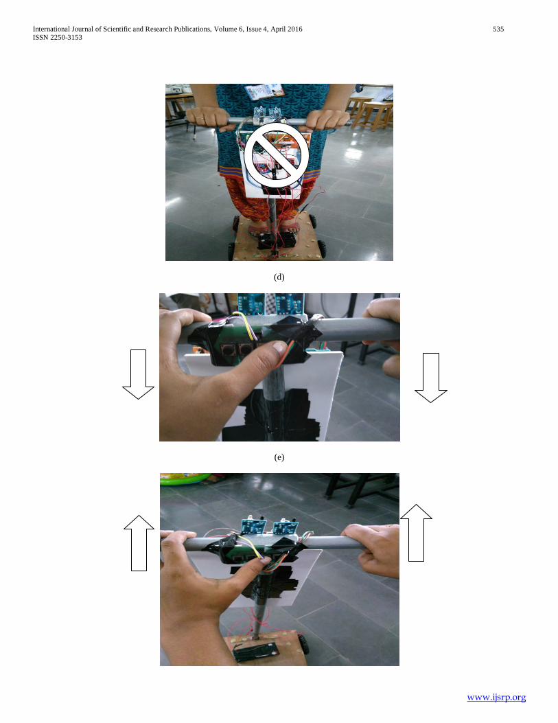
(d)
(e)

International Journal of Scientific and Research Publications, Volume 6, Issue 4, April 2016 536 ISSN 2250-3153
www.ijsrp.org
(f)
(g)
(h)

International Journal of Scientific and Research Publications, Volume 6, Issue 4, April 2016 537 ISSN 2250-3153
www.ijsrp.org
(i) Web of cam Sensor operations (a) When the sensor1 and sensor 2 is on then the E-bike moves forward. (b) When the sensor1 and sensor 2 is off then the E-bike get stops. (c) When the sensor1 is off and sensor 2 is on then the E-bike moves left side. (d) When the sensor1 is on and sensor 2 is off then the E-bike moves right side. Switch operations (e) When switch 1 is pressed the e-bike moves forward. (f) When switch 2 is pressed the e-bike moves backward. (g) When switch 3 is pressed the e-bike moves righ. (h) When switch 4 is pressed the e-bike moves left.
IV. CONCLUSION The paper has been successfully designed and tested. It has been mainly designed in order to reduce human effort. Many existing systems have discussed about the E-bikes and have proposed many methods for reducing their efforts. But still there is a difficulty in moving manually. So, in order to avoid that difficulty, instead of walking in campus electrically or by gestures, our project succeeded in moving the wheel chair using hand movements. When the hand movements are given by the person standing on the e-bike, using IR sensors or manual switch operations the commands are received, and according to those movements the motors will move which in turn moves the E-bike.
REFERENCES [1] WorldPopulationAgeing19502050.PopulationDivision,DESA,UnitedNation
s.[http://www.un.org/esa/population/publications/worldageig] [2] Bouri M, Stauffer Y, Schmitt C, Allemand Y,Gnemmi S, Clavel R,
Metrailler P, Brodard R: TheWalkTrainer: A Robotic System for Walking
[3] Muetze and Y. C. Tan, Electric Bicycles, IEEE Indus try Applications Magazine, July/August, 12-21, 2007.
[4] A. Muetze, A.G. Jack, and B.C. Mecrow, Brushless-dc motor usingsoft magnetic composites as a direct drive in an electric bicycle, Proc. 9th European Conf. Power Electronics and Applications (EPE), Graz,2001, 350 Home Automation System," IEEE Transactions on Consumer Electronics, vol. 52, pp. 837-843, August 2006. (Pubitemid 44593712).
[5] E.A. Lomonova, A.J.A. Vandenput, J. Rubacek, B. d’Herripon, and G. Roovers, Development of an improved electrically assisted bicycle, Proc. 2002 IEEE Industry Applications Soc. Ann. Meeting, 2002, 384–389.
[6] J. Rouwendal, An Economic Analysis of Fuel Use per Kilometer by Private Cars, Journal of Transport Eco-nomics and Policy, 30(1), 1996, 3-14.
[7] W-S. Chee , S. Patwardhan and M. Tomizuka "Lane Change Maneuvers: Experimental Study", Advanced Automtive Technologies 1995,vol. 56, pp.79 -84 1995
[8] C. Cherry and R. Cervero, “Use Characteristics and Mode Choice Behavior of Electric Bike Users in China,” Trans- port Policy, Vol. 14, No. 3, 2007, pp. 247-257. doi:10.1016/j.tranpol.2007.02.005
[9] J. Gardner, “Electrohydraulic/Air Bike,” US Patent No. 4942936, 1990. [10] M. Broucke and P. Varaiya "The Automated Highway System: A
Transportation Technology for the 21st Century", Proceedings of the13th IFAC World Congress, vol. Q, pp.141 -146 1996
AUTHORS First Author – Ravi Teja ch.v.,Assistant professor,Anurag college of engineering,[email protected] second Author – Ch.Pujitha, B.tech, Anurag College of engineering and [email protected] Third Author – S.Gayatri,B.tech, Anurag College of engineering [email protected] Fourth Author – V.Jalander, B.tech, Anurag College of engineering and [email protected] Fifth Author- Ch.Kavitha,B.tech,Anurag College of enginerring [email protected] Correspondence Author –. Mr.Ravi Teja Ch.V,Assistant professor, Anurag college of engineering, [email protected], ph:8019124887


![Campus FullMap red [0119] · Bike Path Proposed Bike Path Bike Rack Geaux Vélo Station Landmarks Lactation Station MAIN CAMPUS SAFETY | See Something, Say Something UniversityUpdates.com](https://static.fdocuments.us/doc/165x107/5f287b97c6bb4d4350643470/campus-fullmap-red-0119-bike-path-proposed-bike-path-bike-rack-geaux-vlo-station.jpg)