
The Frank Sprague Electric Locomotive - Railway & Locomotive
Upload
yicheng-zhuCategory
view
37download
3
Final Presentation
1

Team members
Yicheng Zhu
Lab designer
Felipe Augusto
Schwarzbach Caron
Leader
FEA analysis designer
Andrew Oh
Editor/Communications
2

Customer Requirements (contract) 1. Select concept for a locomotive bumper
a. 100kph impact
b. Cannot be longer than 6m
c. Low Cost (price should be a small fraction of the total cost of a train)
1. FEA analysis and experimental data on feasibility of a material in these conditions
a. Impact yields Head Injury Criterion or (HIC) < 700
1. Ethical position on prevented-suicide
2. Qualitative Discussion on overall design
3

Proposed Concept
“Catch Design”
4
need to design material

Background: Accident Numbers
•In 2015, 1211 total caualties (244 deaths and 967 injuries) in US, and 145 total casualties in California •In EU&US, from 2007~2012,29,800 consider suicide, 18,850 for suicide!
• The deaths per ton mile for rail are 37% higher than for truck transportation•Economic costs associated with pedestrian impacts are measured in billions of dollars.
[1] http://safetydata.fra.dot.gov/OfficeofSafety/default.aspx.
[2] European Railway Agency, “Railway safety in the European Union,” Tech. Rep., 2014. http://business.tenntom.org/
5

Ethics of Suicide Prevention
• Where Are They Now? - published study by Dr. Seiden followed up on five hundred and fifteen people who were prevented from attempting suicide at the bridge
• The findings confirm previous observations that suicidal behavior is crisis-oriented and acute in nature,’ Seiden concluded;
• If you can get a suicidal person through his crisis—Seiden put the high-risk period at ninety days—chances are extremely good that he won’t kill himself later
http://www.ncbi.nlm.nih.gov/pubmed/2171316

Design Concept
Catch and decelerate
Carry the load until it stops
7
[1] B. E. Paden, P. M. Kelly, J. Hines, D. Bothman and C. Simms, “On the feasibility of life-saving locomotive bumpers,” submitted for publication

Qualitative Design
Qualitative discussion on catch systems
Possible sources of failure
Train rolls the pedestrian under the tracks
Partial catch of pedestrian
Collision with unwanted objects
Material degradation (debris and weather)8

Qualitative Design
Qualitative discussion on catch systems
Possible sources of failure and proposed solutions
Train rolls the pedestrian under the tracks => Integrated Ramp
Partial catch of pedestrian => Motorized Platform
Collision with unwanted objects => Safety Net and Layers of Foams
Material degradation (debris and weather) => Weatherproofing
Government safety regulations for material replacement
9

10
Layered foam design. Low yield: green; medium yield: yellow; viscoelastic:
orange
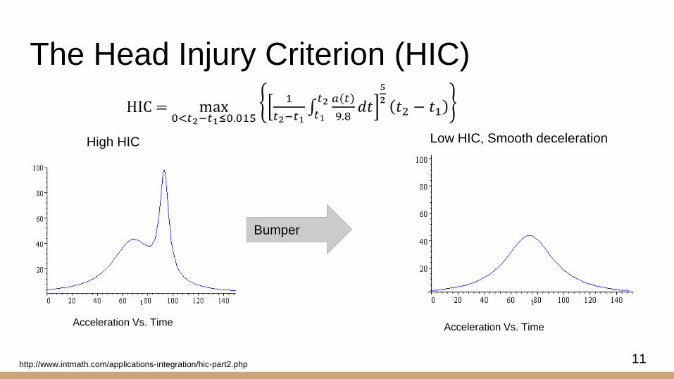
The Head Injury Criterion (HIC)
High HIC Low HIC, Smooth deceleration
Bumper
Acceleration Vs. Time Acceleration Vs. Time
http://www.intmath.com/applications-integration/hic-part2.php11

HIC constant acceleration analysis for high
level (initial) material selection.
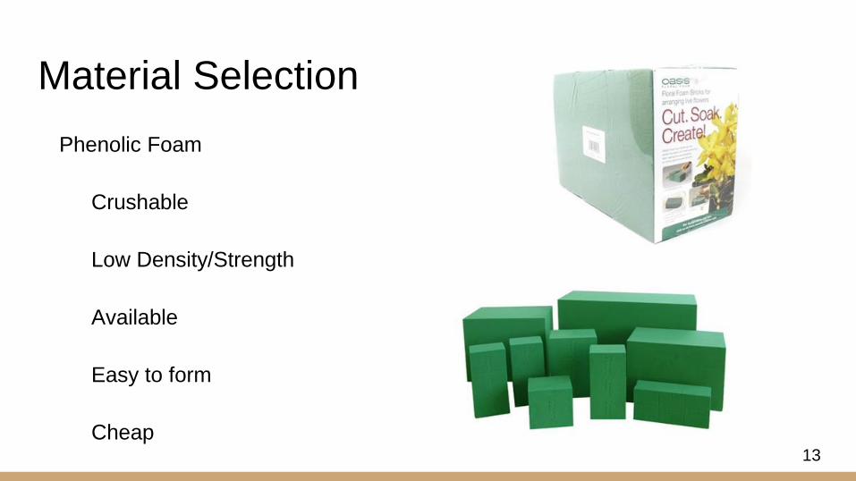
Material Selection
Phenolic Foam
Crushable
Low Density/Strength
Available
Easy to form
Cheap13

Methodology
1. Select the material suitable for a locomotive bumper. [phenolic foam]
a. material data with compression test [MTS Test] = stress vs strain curve
b. material data with ball drop test [ballistics lab] = acceleration vs time of
impact material
c. Simulate ball drop test with MTS data
d. Compare experimental and accuracy [HIC vs Velocity of impact material]
2. Analyze the comparison to confirm the accuracy of simulation
Simulate high velocity impact to obtain material feasibility.
14

Quasistatic Compression Tests
Procedure
○ crushes 80% of specimen’s initial length
● Yields
○ the stress-strain curve
○ material strength and other properties
15

Quasistatic Compression Tests - Machined Specimens
Solid Foam Foam with Axial
Holes
Foam with
Transversal Holes 16

vs.
Transversal
Loading
Axial
LoadingHoles in
blocks
17
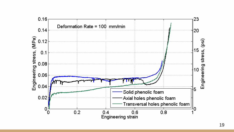
19

Desired
Material
20

Quasistatic Compression Tests - Different composition
Green
high density
Phenolic foam
Blue
low density
Phenolic foam
Pink
high density
Phenolic foam
Brown
low density
Phenolic foam 21
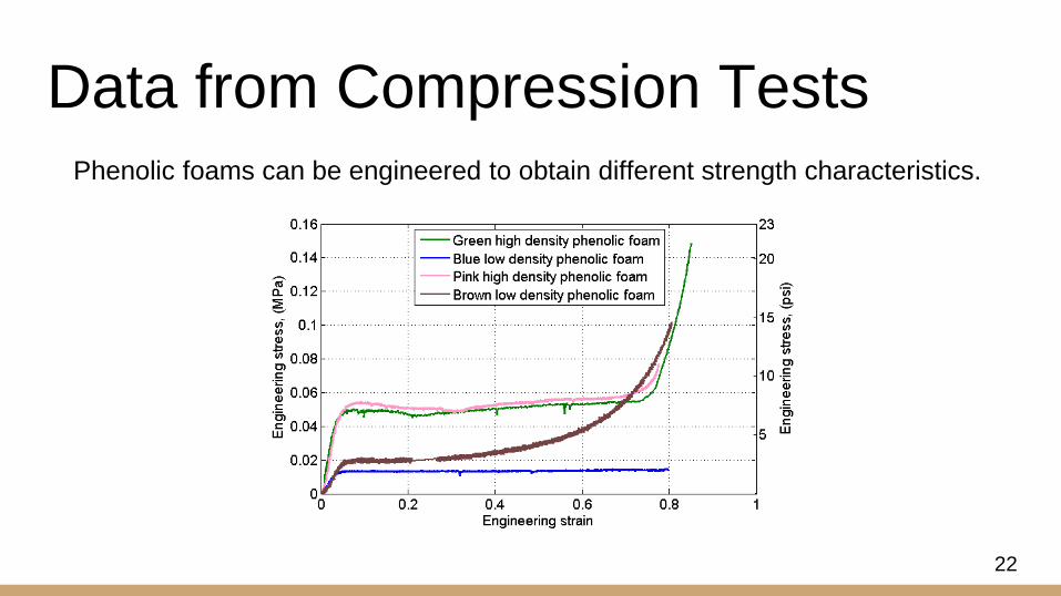
Data from Compression TestsPhenolic foams can be engineered to obtain different strength characteristics.
22

Ballistic Lab - Low Velocity impacts
In the Ballistic Lab an Al alloy with a head-form
was mounted in a tripod drop system (Triax
2010, Alpha Automation Inc, Ewing
Township, NJ)
It was dropped from differents height yielding to
impacts at different low velocities.
The HIC, peak acceleration, impact velocity,
and impact angle were outputs of the
equipment. Triax 2010 HIC test setup
23

Ballistic Lab - Low Velocity impacts
25
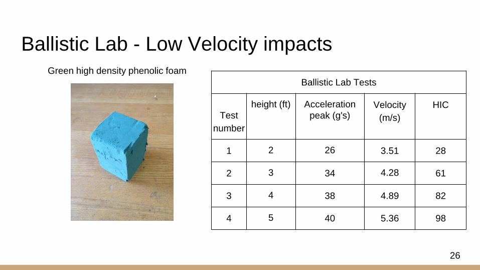
Ballistic Lab Tests
Test
number
height (ft) Acceleration
peak (g's)Velocity
(m/s)
HIC
1 2 26 3.51 28
2 3 34 4.28 61
3 4 38 4.89 82
4 5 40 5.36 98
Ballistic Lab - Low Velocity impactsGreen high density phenolic foam
26
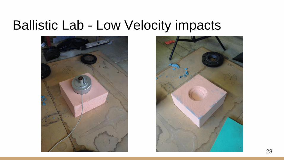
Ballistic Lab - Low Velocity impacts
28

Ballistic Lab Tests
Test
number
height (ft) Acceleration
peak (g's)Velocity
(m/s)
HIC
1 3 25 4.16 31
2 4 32 4.90 64
3 5 33 5.39 75
Ballistic Lab - Low Velocity impactsPink high density phenolic foam
29
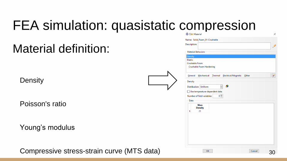
FEA simulation: quasistatic compression
Material definition:
Density
Poisson's ratio
Young’s modulus
Compressive stress-strain curve (MTS data) 30
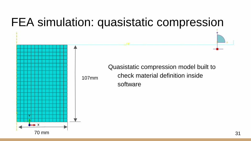
FEA simulation: quasistatic compression
107mm
70 mm
Quasistatic compression model built to
check material definition inside
software
31

FEA simulation: quasistatic compression
32

33
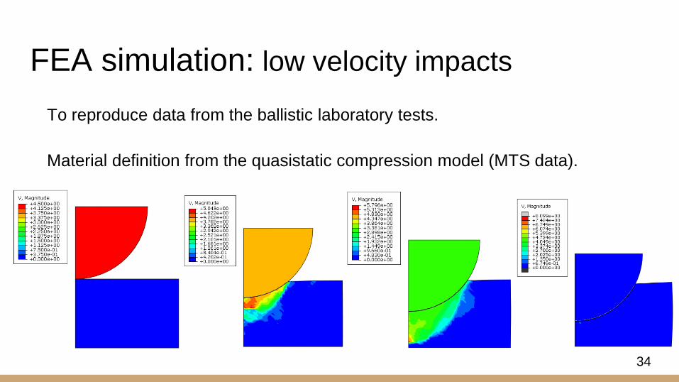
FEA simulation: low velocity impacts
To reproduce data from the ballistic laboratory tests.
Material definition from the quasistatic compression model (MTS data).
34

An Al alloy missile impacting in
a phenolic foam
Input for simulation: Initial
velocity of the impact
Time step of 15 ms based on
the HIC equation
FEA simulation: low velocity impacts
35
36

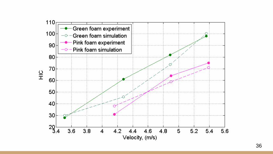
Validation for low velocity impacts
Parameters data were taken from the MTS!
FEA simulation: low velocity impacts
37

Strain-rate dependence
M. F. Ashby, T. Evans, N. A. Fleck, L. J. Gibson, J. W. Hutchinson, and H. N. G. Wadley, Metal
Foams: A Design Guide. Woburn, MA: Society of Automotive Engineers Inc, 2000.
● No temperature dependence
● Rigid polyurethane data
● Strain-rate of 30/s
Plastic collapse strength of a foam
σ : material yield strength at
: strain-rate
T : operating temperature
A and i : material properties
38
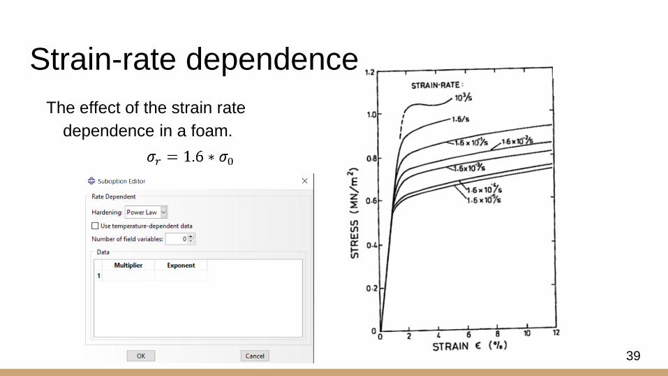
The effect of the strain rate
dependence in a foam.
Strain-rate dependence
39

Initial velocity of 100kph as input
Material definition from the
simulations previously done
Strain-rate dependency was
implemented
FEA simulation: high velocity impacts
40

FEA simulation: high velocity impacts
41
● Our FEA model predicts that we
meet the design requirement.
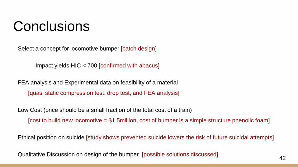
Conclusions
Select a concept for locomotive bumper [catch design]
Impact yields HIC < 700 [confirmed with abacus]
FEA analysis and Experimental data on feasibility of a material
[quasi static compression test, drop test, and FEA analysis]
Low Cost (price should be a small fraction of the total cost of a train)
[cost to build new locomotive = $1.5million, cost of bumper is a simple structure phenolic foam]
Ethical position on suicide [study shows prevented suicide lowers the risk of future suicidal attempts]
Qualitative Discussion on design of the bumper [possible solutions discussed]
Our FEA model is validated with 2 lab tests. (MTS & Drop test)
42

Future work for a Locomotive Bumper
High velocity experiments
Analyze material strain-rate dependence
Full body dynamic analysis (FEA simulation)
Real impact experiments
43

Thank you...
UCSB Faculty:
Brad Paden
Frank Zok
Kirk Fields
Tyler Susko
UCSB Students:
Wessam Aziz
James
Company:
Oasis® Floral Products
44

Questions or Comments?
45

HIC tests - Blue Foam
46

47

Bumper length analysis.
[1] B. E. Paden, P. M. Kelly, J. Hines, D. Bothman and C. Simms, “On the feasibility of life-saving locomotive bumpers,” submitted for publication 48

4 Concepts for bumper
• bumper 1 catches the pedestrian and carries him/her with the locomotive until the train can stop.
• bumper 2 impacts the pedestrian and accelerates him/her off the track.
• bumper 3 first accelerates and then decelerates the pedestrian off the track at zero velocity.
• bumper 4 is a mechanism that is disconnected from the locomotive at the time of impact with the pedestrian.
[1] B. E. Paden, P. M. Kelly, J. Hines, D. Bothman and C. Simms, “On the feasibility of life-saving locomotive bumpers,” submitted for publication 49

Project scope: material design
• Material needs
• Low Density (small inertial forces)
• Low Strength (small forces)
• Reasonable Toughness (absorb energy)
Soft impact
In the Qualitative Ashby map
Material field chosen == Foams.
50
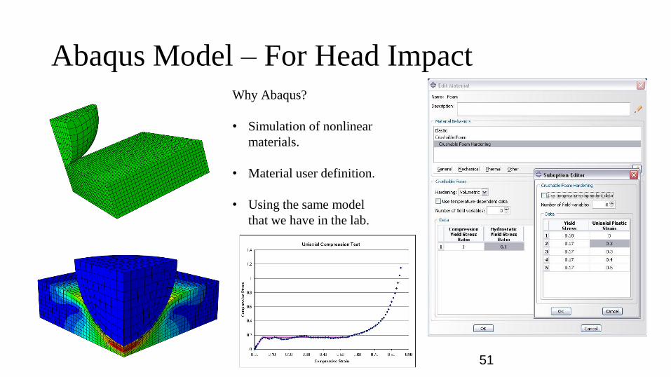
Abaqus Model – For Head ImpactWhy Abaqus?
• Simulation of nonlinear
materials.
• Material user definition.
• Using the same model
that we have in the lab.
51