
Seminar Report - 123seminarsonly.com€¦ · Web viewThe word on just about every . ... A pod...
44
CHAPTER-1 INTRODUCTION 1
Transcript of Seminar Report - 123seminarsonly.com€¦ · Web viewThe word on just about every . ... A pod...

CHAPTER-1INTRODUCTION
1
INTRODUCTION TO AIRBORNE INTERNET
The word on just about every Internet user's lips these days is "broadband." We
have so much more data to send and download today, including audio files, video files
and photos, that it's clogging our wimpy modems. There's a new type of service being
developed that will take broadband into the air.
The communication payload of HALO aircraft is at the apex of a wireless super-
metropolitan area network. The links are wireless, broadband and line of sight.
Subscribers access service on demand and will be able to exchange video, high-
resolution images, and large data files. Information addressed to non-subscribers or to
recipients beyond the regions served by the HALO network will be routed through the
dedicated HALO Gateway connected to the public switched network or via business
premise equipment owned and operated by service providers connected to the public
networks
.
Angel Photo courtesy Angel Technologies
This diagram shows how the HALO Network will enable a high-speed wireless Internet
connection
2

At least three companies are planning to provide high-speed wireless Internet
connection by placing aircraft in fixed patterns over hundreds of cities. Angel
Technologies is planning an airborne Internet network, called High Altitude Long
Operation (HALO), which would use lightweight planes to circle overhead and provide
data delivery faster than a T1 line for businesses. Consumers would get a connection
comparable to DSL. Also, AeroVironment has teamed up with NASA on a solar-
powered, unmanned plane that would work like the HALO network, and Sky Station
International is planning a similar venture using blimps instead of planes.
The computer most people use comes with a standard 56K modem, which means
that in an ideal situation your computer would downstream at a rate of 56 kilobits per
second (Kbps). That speed is far too slow to handle the huge streaming-video and music
files that more consumers are demanding today. That's where the need for bigger
bandwidth -- broadband -- comes in, allowing a greater amount of data to flow to and
from your computer. Land-based lines are limited physically in how much data they can
deliver because of the diameter of the cable or phone line. In an airborne Internet, there is
no such physical limitation, enabling a broader capacity.
Several companies have already shown that satellite Internet access can work.
The airborne Internet will function much like satellite-based Internet access, but without
the time delay. Bandwidth of satellite and airborne Internet access are typically the same,
but it will take less time for the airborne Internet to relay data because it is not as high
up. Satellites orbit at several hundreds of miles above Earth. The airborne-Internet
aircraft will circle overhead at an altitude of 52,000 to 69,000 feet (15,849 to 21,031
meters). At this altitude, the aircraft will be undisturbed by inclement weather and flying
well above commercial air traffic.
3

Networks using high-altitude aircraft will also have a cost advantage over
satellites because the aircraft can be deployed easily -- they don't have to be launched
into space. However, the airborne Internet will actually be used to compliment the
satellite and ground-based networks, eplace them. These not rairborne networks will
overcome the last-mile barriers facing conventional Internet access options. The "last
mile" refers to the fact that access to high-speed cables still depends on physical
proximity, and that for this reason, not everyone who wants access can have it. It would
take a lot of time to provide universal access using cable or phone lines, just because of
the time it takes to install the wires. An airborne network will immediately overcome the
last mile as soon as the aircraft takes off.
The airborne Internet won't be completely wireless. There will be ground-based
components to any type of airborne Internet network. The consumers will have to install
an antenna on their home or business in order to receive signals from the network hub
overhead. The networks will also work with established Internet Service Providers
(ISPs), who will provide their high-capacity terminals for use by the network. These ISPs
have a fiber point of presence their fiber optics are already set up. What the airborne
Internet will do is provide an infrastructure that can reach areas that don't have
broadband cables and wires.
The HALO network will provide consumers with a broadband digital utility for
accessing multimedia services, the internet, and entertainment services. The network at
the subscriber's premise will be standards based and employ a user interface as simple as
today's typical consumer modem. Consumers will be able to access video, data, and the
internet rates ranging from 1 to 5 Mbps. Angle will offer higher data rates at the
broadband market matures.
4

CHAPTER-2
BACKGROUND
5

BACKGROUND
Given the lack of infrastructure to support the current and projected demands for
broadband data communication, an intense race has begun to deploy broadband
networks. To satisfy businesses and consumers, Internet Service providers ("ISPs") are
the majors in delivering internet access service.
Today the access service is provided by five types of competitors:
National ISPs ( e.g. AOL, CompuServe, Microsoft Network, VSNL)
Regional Bell Operating Companies ("RBOCs")
Independent (Local) ISPs
Cable Operators
Wire service providers (Satellites, or terrestrial wireless via millimeter waves at
the LMDS and 38 GHz bands, wireless local loop at the PCS bands, or packet
relay at ISM )
About 70 percent of homes occupied by customers are being served by large
national ISPs. The remaining 30 percent of customer's homes are being served by local
ISPs that range in size from hundreds to tens of thousands of customers. Most consumers
are utilizing 29\8.8 Kbps dial-up modems, and a small percent have already migrated to
56 Kbps modems. Most businesses are utilizing DS-1 connections (1.544Mbps).
6

The Local ISP
The local ISPs are perhaps the most entrepreneurial and fastest growing segment
of the market, expanding at rates approaching 75 percent per year. In order to maintain
this rapid rate of growth in the face of new competition from the RBOs and the cable
companies, these local ISPs are anxious to adopt new technologies that will allow them
to differentiate their services.
The local ISPs think they will be required to provide megabit per second rates to
homes and business in order to survive. However, they are precluded from using the
cable infrastructure as cable companies are viable competitors to them. Similarly, the
RBOCs plan to offer high-speed Internet access through Digital Subscriber line ("DSL")
services and may also compete directly with the local ISPs. Whereas, the HALO
Network will allow the ISPs to offer distance-insensitive connections within the HALO
Network service area, bypassing the Local Exchange Carriers and Interchange Carriers,
to substantially reduce their cost of service.
Cable operators are facing a significant threat from direct broadcast satellite
companies and wireless cable companies. With the advent of cable modems, the cable
TV companies see a new opportunity in two way data communication. Although this
would appear to be an excellent diversification strategy, there are technical challenges
affecting the delivery of an effective two way broadband service. Specifically, cable
systems are designed to send signals one way potentially, i.e. broadcast video from head
end to consumer. In order for this infrastructure to deliver symmetric two way
transmission, the cable operators will be required to invest in switching backbones and
line upgrades.
7

CHAPTER-3
HALO NETWORK
8

HALO NETWORK
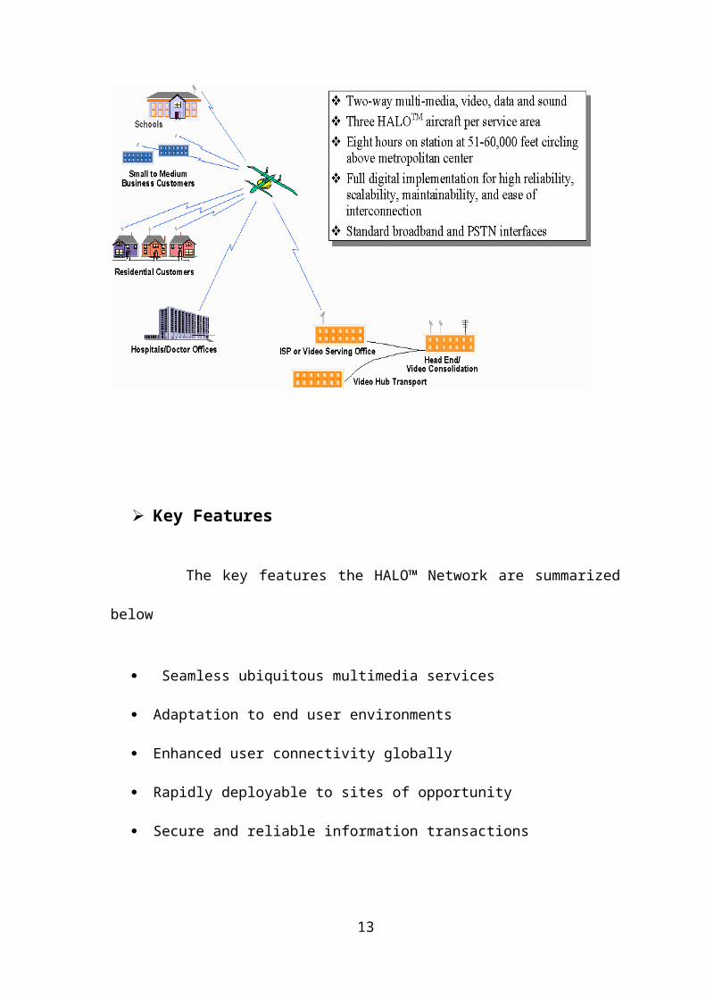
Overall Concept
The attributes of the HALO™ Network are illustrated in the fig. below. Many
types of subscribers will benefit from the low price of HALO™ Network broadband
services schools, families, hospitals, doctor's offices, and small to medium size
businesses. The equipment will connect to existing network and telecommunications
equipment using standard broadband protocols such as ATM and SONET. The HALO™
Gateway provides access to the Public Switched Telephone Network (PSTN) and to the
internet backbone for such services as the World Wide Web and electronic commerce.
9
Key Features
The key features the HALO™ Network are summarized below
Seamless ubiquitous multimedia services
Adaptation to end user environments
Enhanced user connectivity globally
Rapidly deployable to sites of opportunity
Secure and reliable information transactions
Bandwidth on demand provides efficient use of available spectrum
Service Attributes
There are various classes of service to be provided .A consumer service would
provide 1-5 Mbps communication links. A business service would provides 5-12.5 Mbps
links .Since the links would be "bandwidth-on-demand," the total available spectrum
would be time-shared between the various active sessions. The nominal data rates would
be low while the peak rates would expand to a specified level. A gateway service can be
provided for "dedicated" links of 25-155 Mbps. Based on the LMDS spectrum and 5-fold
reuse, the service capacity would be 10000 to 75000 simultaneously , symmetrical T1
circuits (1.5 Mbps) per communication payload. The HALO Aircraft would provide
urban and rural coverage from a single platform to provide service to:
100-750000 subscribers
40-60 mile diameter service area (1250 to 2800 square miles)
Network Access
10

Various methods for providing access to the users on the ground are feasible. The
figure below shows one approach where each spot beam from the payload antenna serves
a single "cell" on the ground in a frequency-division multiplex fashion with 5 to 1
frequency reuse, four for subscriber units and the fifth for gateways to the public network
and to high rate subscribers. Other reuse factors such as 7:1 and 9:1 are possible. Various
network access approaches are being explored.
Cell Coverage by Frequency Division Multiplexing using Spot Beams
Network Services
The HALO™ mode provides a multitude of connectivity options as shown below.
It can be used to connect physically separated Local Area Networks (LANs) within a
11

corporate intranet through frame relay adaptation or directly though LAN bridgers and
routers. Or it can provide video conference links through standard ISDN or T1 interface
hardware. The HALO™ Network may use standard SONET and ATM protocols and
equipment to take advantage of the wide availability of these components.
12
CHAPTER-4HALO™ NETWORK ARCHITECTURE
13
HALO™ NETWORK ARCHITECTURE
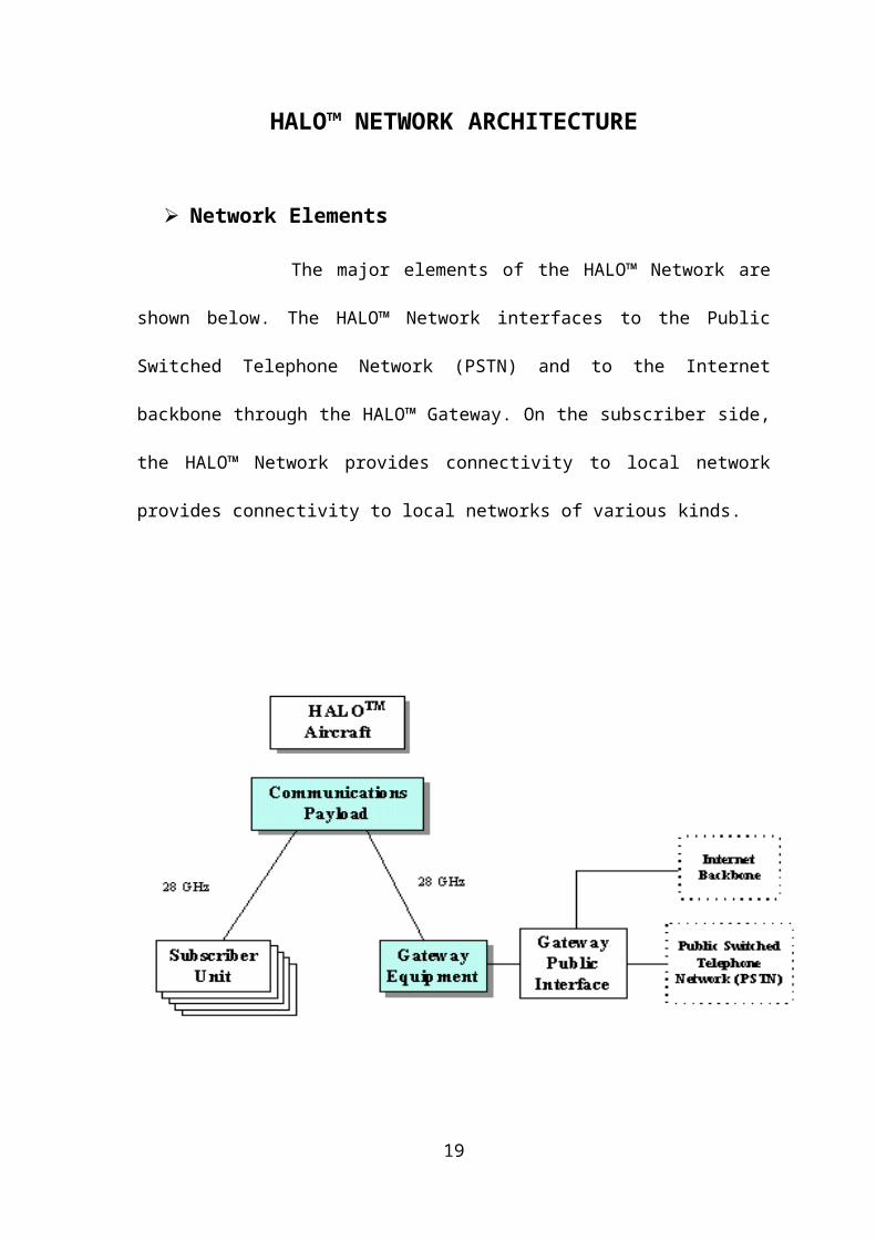
Network Elements
The major elements of the HALO™ Network are shown below. The HALO™
Network interfaces to the Public Switched Telephone Network (PSTN) and to the
Internet backbone through the HALO™ Gateway. On the subscriber side, the HALO™
Network provides connectivity to local network provides connectivity to local networks
of various kinds.
The HALO™ Network Architecture
14

Network Architecture
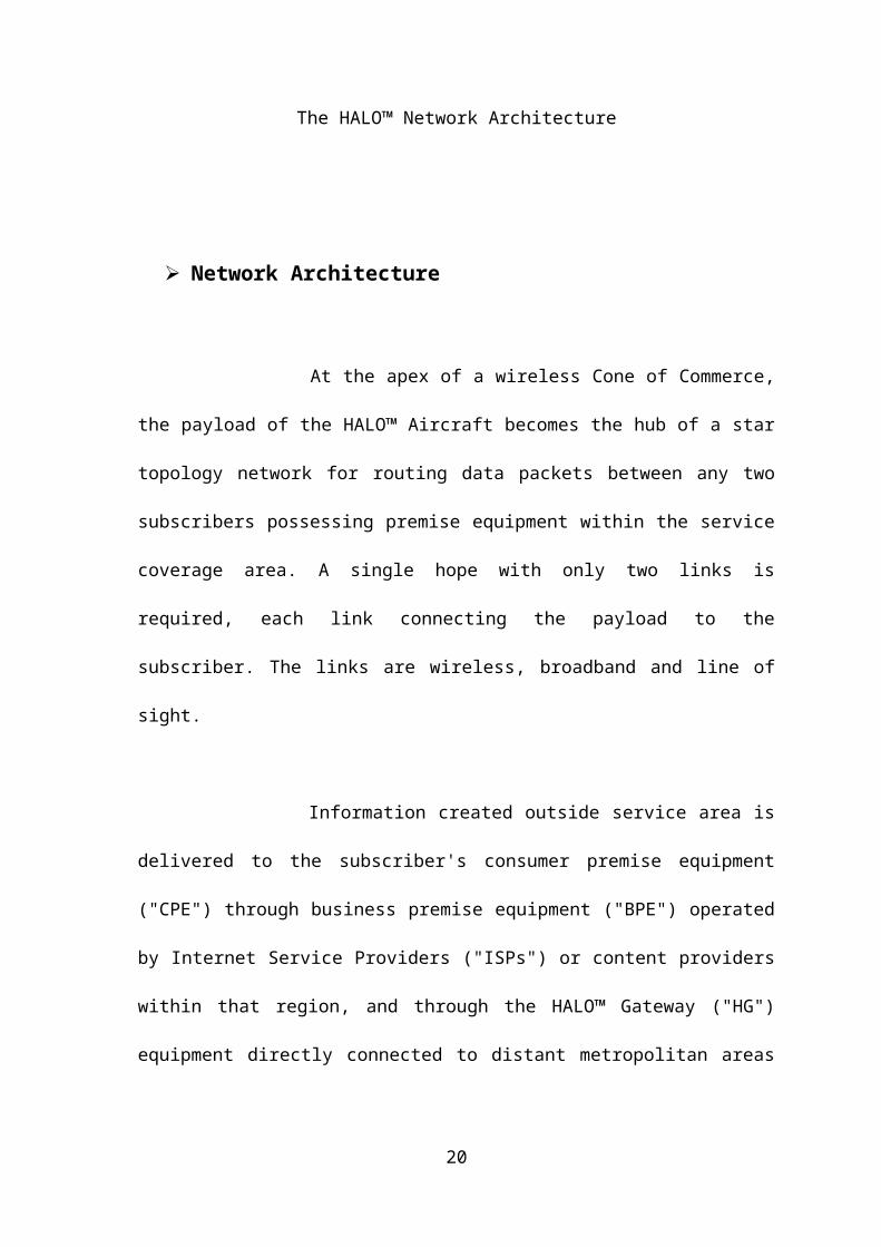
At the apex of a wireless Cone of Commerce, the payload of the HALO™
Aircraft becomes the hub of a star topology network for routing data packets between
any two subscribers possessing premise equipment within the service coverage area. A
single hope with only two links is required, each link connecting the payload to the
subscriber. The links are wireless, broadband and line of sight.
Information created outside service area is delivered to the subscriber's
consumer premise equipment ("CPE") through business premise equipment ("BPE")
operated by Internet Service Providers ("ISPs") or content providers within that region,
and through the HALO™ Gateway ("HG") equipment directly connected to distant
metropolitan areas via leased trunks. The HG is a portal serving the entire network.
It avails system-wide access to content providers and it allows any subscriber to
extend their communications beyond the HALO™ Network service area by connecting
them to dedicated long-distance lines such as inter- metro optical fiber.
The HALO™ Network
The CPE, BPE and HG all perform the same functions; use a high gain antenna
that automatically tracks the HALO™ Aircraft; extract modulated signals conveyed
through the air by millimeter waves; convert the extracted signals to digital data; provide
standards-based data communications interfaces, and route the digital data to information
appliances, personal computers, and workstations connected to the premise equipment.
15

Thus, some of the technologies and components, both hardware and software, will be
common to the designs of these three basic network elements.
The CPE, BPE and HG differ in size, complexity and cost, ranging from the CPE
which is the smallest, least complex ,lowest priced and will be expressively built for the
mask market; followed by the BPE, engineered for a medium size business to provide
access to multiple telecommuters by extending the corporate data communications
network; to the HG which provides high bandwidth wireless data trunking to Wide Area
Network ("WANs") maintained and operated by the long distance carriers and content
handlers who wish to distribute their products widely.
In other words the CPE is a personal gateway serving the consumer. The BPE is a
gateway for the business requiring higher data rates. The HG, as a major element of the
entire network, will be engineered to serve reliably as a critical network element. All of
these elements are being demonstrated in related forms by terrestrial 38 GHz and LMDS
vendors. Angel will solicit the participation of key component suppliers for adapting
their technologies to the HALO™ Network. As with all wireless millimeter wave links,
high rainfall rates can reduce the effective data throughput of the link to a given
subscriber.
Angel plans to ensure maximum data rates more than 99.7% of the time, reduced
data rates above an acceptable minimum more than 99.9% of the time and to limit
outages to small areas (due to the interception of the signal path by very dense rain
columns) less than 0.1% of the time Angel plans to locate the HG close to HALO ™
16

orbit center to reduce the slant range from its high gain antenna to the aircraft and hence
its signal path length through heavy rainfall.
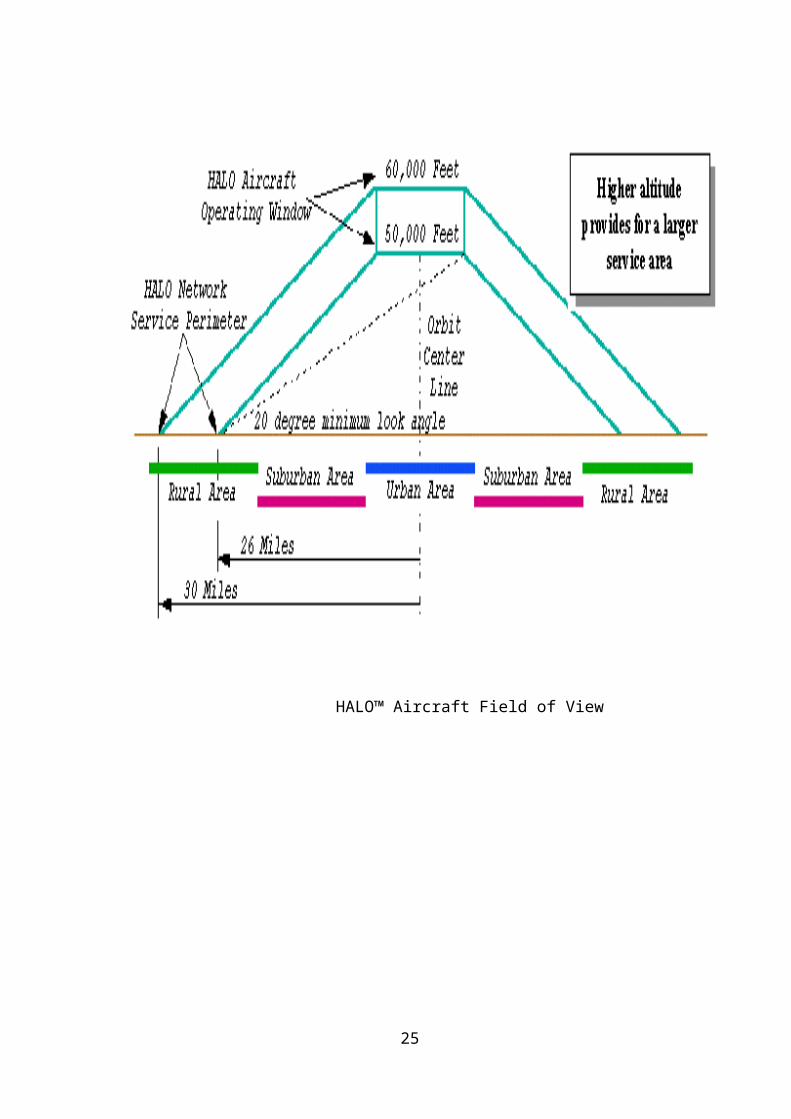
Field of View
Angel assumes the "minimum look angle" (i.e., the elevation angle above the
local horizon to the furthest point on the orbit as seen by the antenna of the premise
equipment) is generally higher than 20 degrees. This value corresponds to subscribers at
the perimeter of the service footprint. In contrast, cellular telephone designers assume
that the line of sight from a customer to the antenna on the nearest base station is less
than 1 degree. Angel chose such a high look angle to ensure that the antenna of each
subscriber's premise equipment will very likely have access to a solid angle swept by the
circling HALO™ Aircraft free of dense objects, and to ensure high availability of the
service during heavy rainfall to all subscribers.
The high look angle also allows the sharing of this spectrum with ground-based
wireless networks since usually high-gain, narrow beams are used and the antenna beams
of the HALO™ and ground-based networks will be separated in angle far enough to
ensure a high degree of signal isolation.
17
HALO™ Aircraft Field of View
18
CHAPTER-5HALO™ AIRCRAFT
19
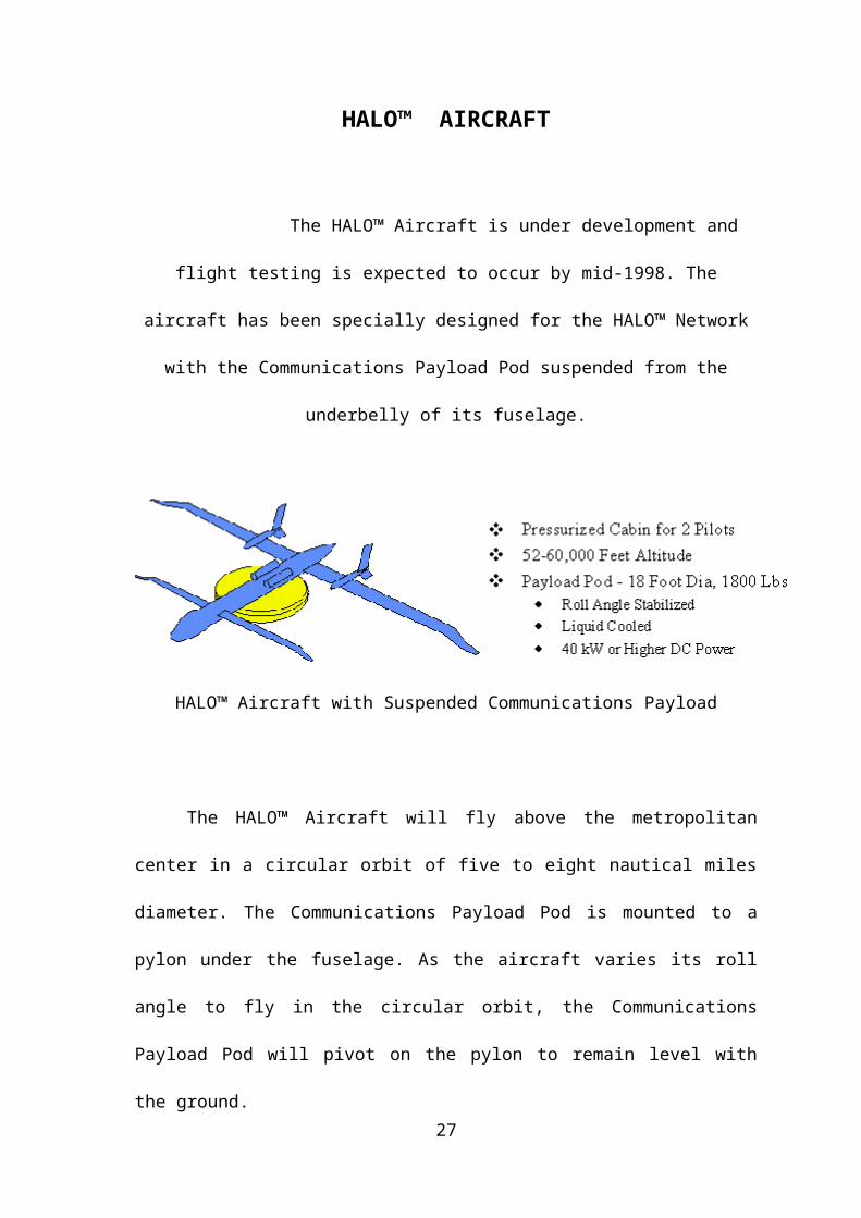
HALO™ AIRCRAFT
The HALO™ Aircraft is under development and flight testing is expected to
occur by mid-1998. The aircraft has been specially designed for the HALO™ Network
with the Communications Payload Pod suspended from the underbelly of its fuselage.
HALO™ Aircraft with Suspended Communications Payload
The HALO™ Aircraft will fly above the metropolitan center in a circular orbit of
five to eight nautical miles diameter. The Communications Payload Pod is mounted to a
pylon under the fuselage. As the aircraft varies its roll angle to fly in the circular orbit,
the Communications Payload Pod will pivot on the pylon to remain level with the
ground.
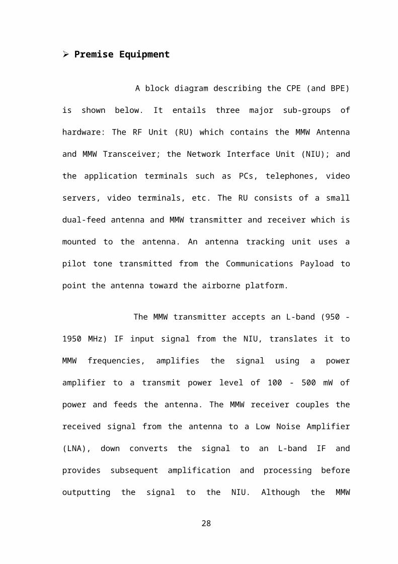
Premise Equipment
A block diagram describing the CPE (and BPE) is shown below. It entails three
major sub-groups of hardware: The RF Unit (RU) which contains the MMW Antenna
and MMW Transceiver; the Network Interface Unit (NIU); and the application terminals
such as PCs, telephones, video servers, video terminals, etc. The RU consists of a small
dual-feed antenna and MMW transmitter and receiver which is mounted to the antenna.
20
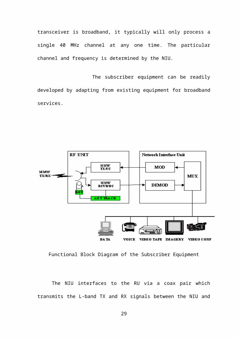
An antenna tracking unit uses a pilot tone transmitted from the Communications Payload
to point the antenna toward the airborne platform.
The MMW transmitter accepts an L-band (950 - 1950 MHz) IF input signal from
the NIU, translates it to MMW frequencies, amplifies the signal using a power amplifier
to a transmit power level of 100 - 500 mW of power and feeds the antenna. The MMW
receiver couples the received signal from the antenna to a Low Noise Amplifier (LNA),
down converts the signal to an L-band IF and provides subsequent amplification and
processing before outputting the signal to the NIU. Although the MMW transceiver is
broadband, it typically will only process a single 40 MHz channel at any one time. The
particular channel and frequency is determined by the NIU.
The subscriber equipment can be readily developed by adapting from existing
equipment for broadband services.
21

Functional Block Diagram of the Subscriber Equipment
The NIU interfaces to the RU via a coax pair which transmits the L-band TX and
RX signals between the NIU and the RU. The NIU comprises an L-band tuner and down
converter, a high-speed (up to 60 Mbps) demodulator, a high-speed modulator,
multiplexers and demultiplexers, and data, telephony and video interface electronics.
Each user terminal will provide access to data at rates up to 51.84 Mbps each way. In
some applications, some of this bandwidth may be used to incorporate spread spectrum
coding to improve performance against interference (in this case, the user information
rate would be reduced).
The NIU equipment can be identical to that already developed for LMDS and
other broadband services. This reduces the cost of the HALO™ Network services to the
consumer since there would be minimal cost to adapt the LMDS equipment to this
application and we could take advantage of the high volume expected in the other
services. Also, the HALO™ RU can be very close in functionality to the RU in the other
22

services (like LMDS) since the primary difference is the need for a tracking function for
the antenna. The electronics for the RF data signal would be identical if the same
frequency band is utilized.
Ease of installation
Angel has designed the HALO Network and the consumer premise equipment
(CPE) to ensure ease of installation by the consumer. The CPE, whether delivered or
purchased through a retailer, is designed for rapid installation and ease of use. The
antenna is self-pointing and is mounted on an outside area offering clear view of the
HALO™ Aircraft.
23

CHAPTER -6
APPLICATIONS
24
APPLICATIONS
The ultimate backend platform for wireless, Airborne is a seamless, turnkey solution the
management and distribution of content of micro-Entertainment networks
Airborne seamlessly handles:
User-friendly, web-based interface
Support for text, voice, image and multimedia files
Client-specific content scheduling and menu generation
Mobile device recognition and optimization
Multilingual content
Extensive usage and analytical reporting
Editorial tools
25

CHAPTER-7FUTURE PLANS
26
FUTURE PLANS
NASA's Sub-space Plans
Not to be left out of the high-flying Internet industry, NASA is also playing a
role in a potential airborne Internet system being developed by AeroVironment. NASA
and AeroVironment are working on a solar-powered, lightweight plane that could fly
over a city for six months or more, at 60,000 feet, without landing. AeroVironment
plans to use these unmanned planes as the carrier to provide broadband Internet access.
The Helios aircraft will be equipped with telecommunications equipment and stay
airborne for six months straight.
27
Helios is currently in the prototype stage, and there is still a lot of testing to
be done to achieve the endurance levels needed for AeroVironment's
telecommunications system. AeroVironment plans to launch its system within three
years of receiving funding for the project. When it does, a single Helios airplane
flying at 60,000 feet will cover a service area approximately 40 miles in diameter.
Helios Aircraft
Weight 2,048 pounds (929 kg)
Wingspan 247 ft (75.3 m)
Length 12 ft (3.7 m)
Wing Area 1,976 square ft (183.6 m2)
Propulsion14 brushless, 2-horsepower,
direct-current electric motors
Range1 to 3 hours in prototype tests
6 months when fully operational
Speed 19 to 25 mph (30.6 to 40.2 kph)
The Helios prototype is constructed out of materials such as carbon fiber,
graphite epoxy, Kevlar and Styrofoam, covered with a thin, transparent skin. The main
pole supporting the wing is made out of carbon fiber, and is thicker on the top than on the
bottom in order to absorb the constant bending during flight. The wing's ribs are made of
28
epoxy and carbon fiber. Styrofoam comprises the wing's front edge, and a clear, plastic
film is wrapped around the entire wing body.
The all-wing plane is divided into six sections, each 41 ft (12.5 m) long. A pod
carrying the landing gear is attached under the wing portion of each section. These pods
also house the batteries, flight-control computers and data instrumentation. Network hubs
for AeroVironment's telecommunications system would likely be placed here as well.
It seems that airborne Internet could take off in the very near future. If and when
those planes and blimps start circling to supplement our current modes of connection,
downloading the massive files we've come to crave for entertainment or depend on for
business purposes will be a snap -- even if we live somewhere in that "last mile."
ADVANTAGES
Unique feature of these solar-electric air-craft that make then appealing platforms
for telecommunications applications include:
Long flight durations up to 6 months or more.
Minimal maintenance cost due to few moving parts.
High levels of redundancy (e. g. aircraft could lose multiple motors and still
maintain station and land safely - most failure modes do not require
immediate response by ground operator)
Highly autonomous controls which enable one ground operator to control
multiple aircraft.
Use of solar energy to minimize fuel costs.
29

Tight turn radius which makes platform appear geostationary from ground
equipment perspective (i. e. enables use of stationary antennas) and enables
multiple aircraft to serve same area using same frequency spectrum.
CHAPTER-8CONCLUSIONS
30

CONCLUSION
Finally I conclude that the HALO aircraft can be thought of as a very tall
tower or very low altitude satellite. Contracted to terrestrial broadband networks, the
HALO Network offers ubiquitous, anyone-to-anyone broadband linkages throughout
the footprint. HALO networks can be introduced to highly promising markets around
the world on a selective basis. "Continuous improvement" is a significant attribute of
the HALO network. It enables Angel to meet the increasing expectations of present
customers, and to open new markets requiring lesser capability by re-assigning
earlier-generation hubs.
31

CHAPTER-9
REFERENCES
32
REFERENCES
1. AIRBORNE INTERNET (Techpapers from ANGEL Technologies Ltd.)
2. www.angelhalo.com
3. www.airborne.com
4. www.nasa.gov
5. www.aerovironment.com
33