Self-Study Program 990193 - · PDF fileService Training Audi New Technology 2009 – 2010...
98
Service Training Audi New Technology 2009 – 2010 Self-Study Program 990193
Transcript of Self-Study Program 990193 - · PDF fileService Training Audi New Technology 2009 – 2010...
Service Training
Audi New Technology 2009 – 2010
Self-Study Program 990193
Audi of America, LLC
Service Training
Printed in U.S.A.
Printed 11/2009
Course Number 990193
©2009 Audi of America, LLC
All rights reserved. Information contained in this manual is
based on the latest information available at the time of printing
and is subject to the copyright and other intellectual property
rights of Audi of America, LLC., its affi liated companies and its
licensors. All rights are reserved to make changes at any time
without notice. No part of this document may be reproduced,
stored in a retrieval system, or transmitted in any form or by
any means, electronic, mechanical, photocopying, recording or
otherwise, nor may these materials be modifi ed or reposted to
other sites without the prior expressed written permission of
the publisher.
All requests for permission to copy and redistribute
information should be referred to Audi of America, LLC.
Always check Technical Bulletins and the latest electronic
repair literature for information that may supersede any
information included in this booklet.
Table of Contents
i
The Self-Study Program provides introductory information regarding the design
and function of new models, automotive components or technologies.
The Self-Study Program is not a Repair Manual!All values given are intended as a guideline only.Refer to the software version valid at the time of publication of the SSP.
For maintenance and repair work, always refer to the current technical literature.
Reference Note
R8 with 5.2L V10 FSI Engine . . . . . . . . . . . . . . . . . . . . . . . . .1
Packaged Ultrasonic Level Sensor (PULS) . . . . . . . . . . . .17
0B5 S Tronic Transmission . . . . . . . . . . . . . . . . . . . . . . . . . .20
Sport Differential . . . . . . . . . . . . . . . . . . . . . . . . . . . . . . . . . .44
Indirect Tire Pressure Monitoring . . . . . . . . . . . . . . . . . . . .69
MMI 3G . . . . . . . . . . . . . . . . . . . . . . . . . . . . . . . . . . . . . . . . . .73
Knowledge Assessment . . . . . . . . . . . . . . . . . . . . . . . . . . .93

Notes
ii
R8 with 5.2L V10 FSI Engine
1
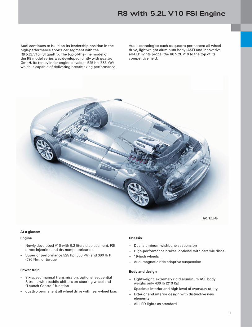
Audi continues to build on its leadership position in the
high-performance sports car segment with the
R8 5.2L V10 FSI quattro. The top-of-the-line model of
the R8 model series was developed jointly with quattro
GmbH. Its ten-cylinder engine develops 525 hp (386 kW)
which is capable of delivering breathtaking performance.
Audi technologies such as quattro permanent all wheel
drive, lightweight aluminum body (ASF) and innovative
all-LED lights propel the R8 5.2L V10 to the top of its
competitive fi eld.
At a glance:
Engine
– Newly developed V10 with 5.2 liters displacement, FSI
direct injection and dry sump lubrication
– Superior performance 525 hp (386 kW) and 390 lb ft
(530 Nm) of torque
Power train
– Six-speed manual transmission; optional sequential
R tronic with paddle shifters on steering wheel and
“Launch Control” function
– quattro permanent all wheel drive with rear-wheel bias
Chassis
– Dual aluminum wishbone suspension
– High-performance brakes, optional with ceramic discs
– 19-inch wheels
– Audi magnetic ride adaptive suspension
Body and design
– Lightweight, extremely rigid aluminum ASF body
weighs only 436 lb (210 Kg)
– Spacious interior and high level of everyday utility
– Exterior and interior design with distinctive new
elements
– All-LED lights as standard
990193_100
R8 with 5.2L V10 FSI Engine
2
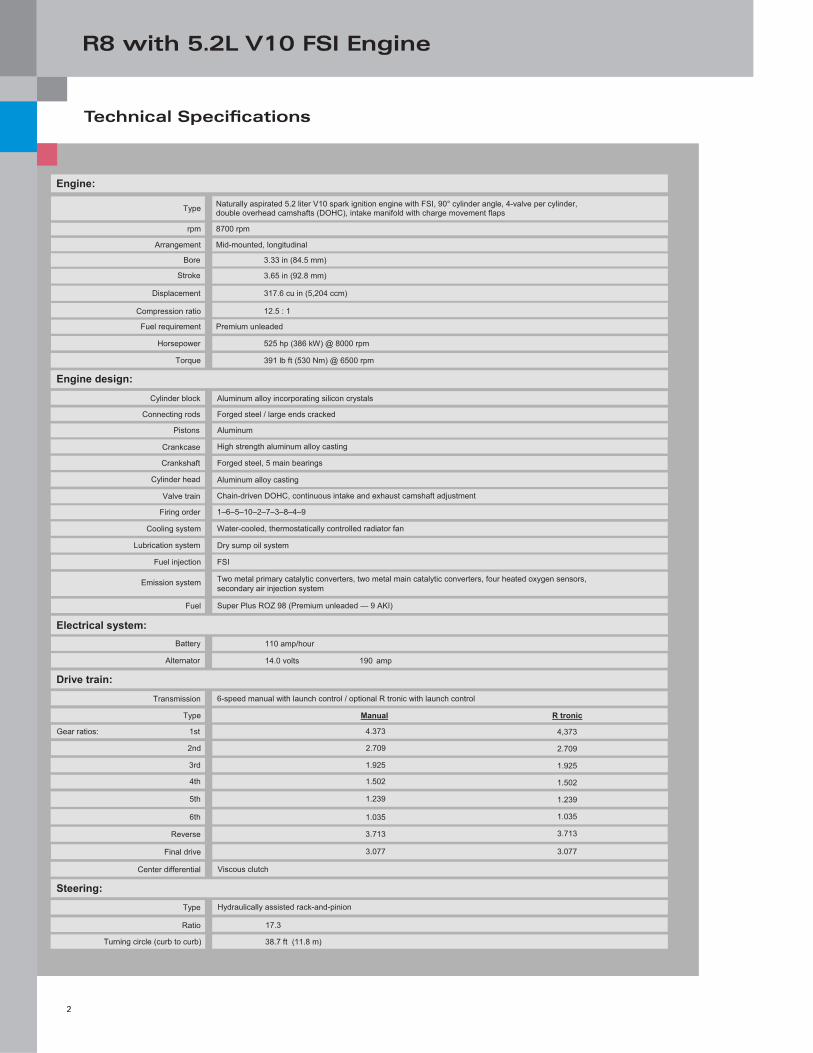
Technical Specifi cations
Engine:
8700 rpm
Mid-mounted, longitudinal
3.33 in (84.5 mm)
3.65 in (92.8 mm)
317.6 cu in (5,204 ccm)
12.5 : 1
Premium unleaded
525 hp (386 kW) @ 8000 rpm
391 lb ft (530 Nm) @ 6500 rpm
Engine design: Aluminum alloy incorporating silicon crystals
Forged steel / large ends cracked
Aluminum
High strength aluminum alloy casting
Forged steel, 5 main bearings
Aluminum alloy casting
Chain-driven DOHC, continuous intake and exhaust camshaft adjustment
1–6–5–10–2–7–3–8–4–9
Water-cooled, thermostatically controlled radiator fan
Dry sump oil system
FSI
Two metal primary catalytic converters, two metal main catalytic converters, four heated oxygen sensors,secondary air injection system
Super Plus ROZ 98 (Premium unleaded — 9 AKI)
110 amp/hour
14.0 volts 190 amp
6-speed manual with launch control / optional R tronic with launch control
Manual R tronic
4.373 4,373
2.709 2.709
1.925 1.925
1.502 1.502
1.239 1.239
1.035 1.035
3.713 3.713
Viscous clutch
Hydraulically assisted rack-and-pinion
17.3
38.7 ft (11.8 m)
Naturally aspirated 5.2 liter V10 spark ignition engine with FSI, 90° cylinder angle, 4-valve per cylinder, double overhead camshafts (DOHC), intake manifold with charge movement flaps
Electrical system:
Drive train:
Steering:
Torque
Horsepower
Compression ratio
Displacement
Stroke
Bore
Arrangement
rpm
Type
Fuel requirement
Cooling system
Firing order
Cylinder head
Crankshaft
Crankcase
Pistons
Connecting rods
Cylinder block
Valve train
Fuel injection
Emission system
Fuel
Lubrication system
Battery
Alternator
Transmission
Type
Gear ratios: 1st
2nd
3rd
4th
5th
6th
3.077 3.077
Reverse
Final drive
Center differential
Type
Ratio
Turning circle (curb to curb)
R8 with 5.2L V10 FSI Engine
3
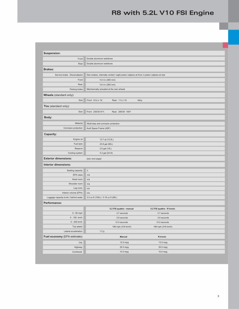
Disc brakes, internally vented / eight piston calipers at front, 4 piston calipers at rear
14.4 in (365 mm)
14.4 in (365 mm)
Mechanically actuated at the rear wheels
Front: 8.5J x 19, Rear: 11J x 19 Alloy
Body:
Audi Space Frame (ASF)
Multi-step anti-corrosion protection
12.7 qt (12.0L)
23.8 gal (90L)
5.3 gal (24.0l)
12.0 mpg 13.0 mpg
15.0 mpg 15.0 mpg
Exterior dimensions: [see next page]
Performance:
Size
Parking brake
Rear
Brakes:
Front
Service brake: Discs/calipers
Reserve
Fuel tank
Engine oil
Corrosion protection
Material
Cooling system
n/a
2
n/a
n/a
n/a
EPA class
Head room
Shoulder room
Seating capacity
Leg room
n/a
3.5 cu ft (100L) / 3.18 cu ft (90L)
Interior volume (EPA)
Luggage capacity trunk / behind seats
5.2 FSI quattro - manual 5.2 FSI quattro - R tronic
3.7 seconds 3.7 seconds
3.9 seconds 3.9 seconds
12.0 seconds 12.0 seconds
196 mph (316 km/h) 196 mph (316 km/h)
1.2 g
0 - 60 mph
0 - 100 km/h
0 - 200 km/h
Top speed
Lateral acceleration
20.0 mpg 20.0 mpg
City
Highway
Combined
Wheels (standard only):
Tire (standard only):
Front: 235/35 91Y, Rear: 295/30 100Y Size
Capacity:
Suspension:
Rear
Front Double aluminum wishbone
Double aluminum wishbone
2.6 gal (10L)
Interior dimensions:
Fuel economy (EPA estimate): Manual R-tronic
R8 with 5.2L V10 FSI Engine
4
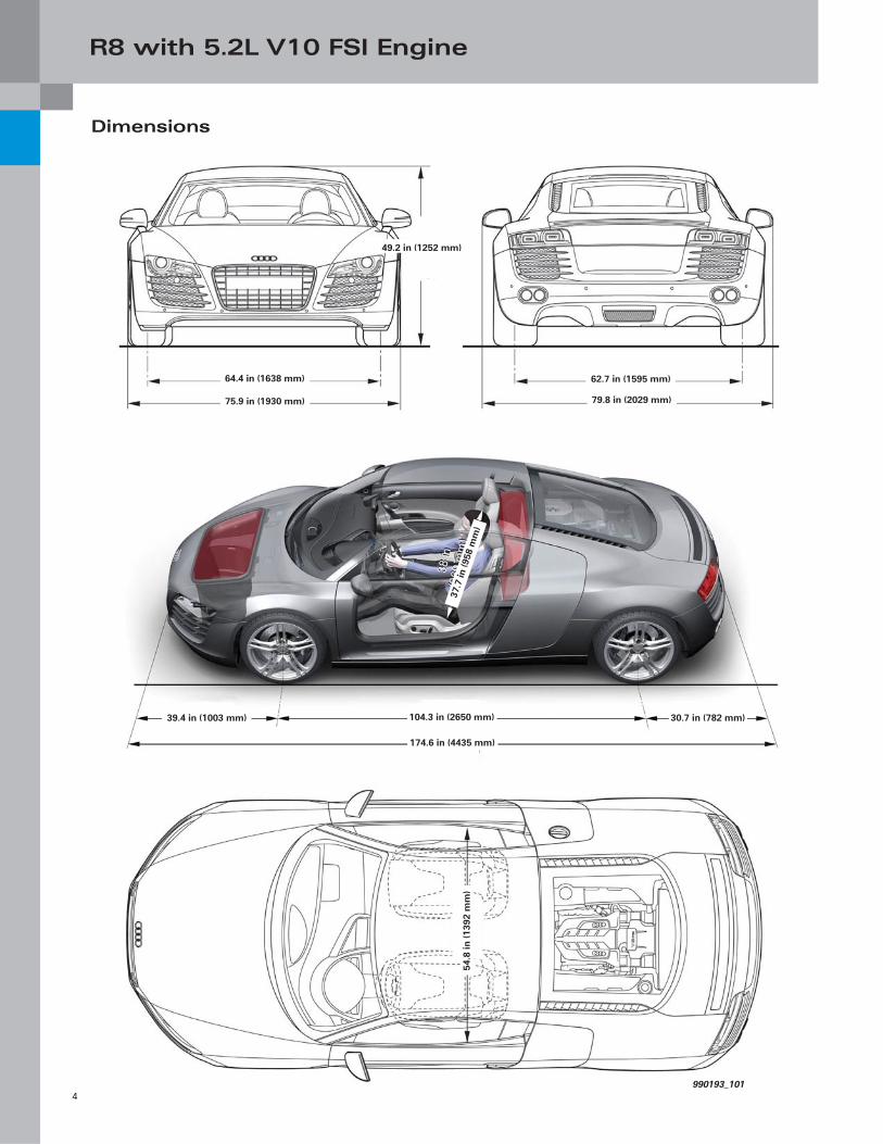
Dimensions
64.4 in (1638 mm)
75.9 in (1930 mm)
49.2 in (1252 mm)
62.7 in (1595 mm)
79.8 in (2029 mm)
37.7
in (9
58 m
m)
39.4 in (1003 mm) 104.3 in (2650 mm)
174.6 in (4435 mm)
30.7 in (782 mm)
990193_101
54.8
in (1
392
mm
)
R8 with 5.2L V10 FSI Engine
5
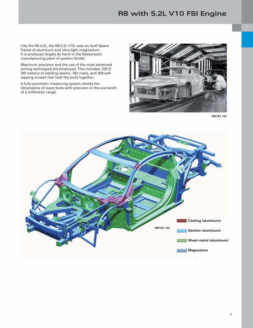
Like the R8 4.2L, the R8 5.2L V10, uses an Audi Space
Frame of aluminum and ultra-light magnesium.
It is produced largely by hand in the Neckarsulm
manufacturing plant of quattro GmbH.
Maximum precision and the use of the most advanced
joining techniques are employed. This includes: 325 ft
(99 meters) of welding seams, 782 rivets, and 308 self-
tapping screws that hold the body together.
A fully automatic measuring system checks the
dimensions of every body with precision in the one-tenth
of a millimeter range.
990193_102
Casting (aluminum)
Section (aluminum)
Sheet metal (aluminum)
Magnesium
990193_103
R8 with 5.2L V10 FSI Engine
6
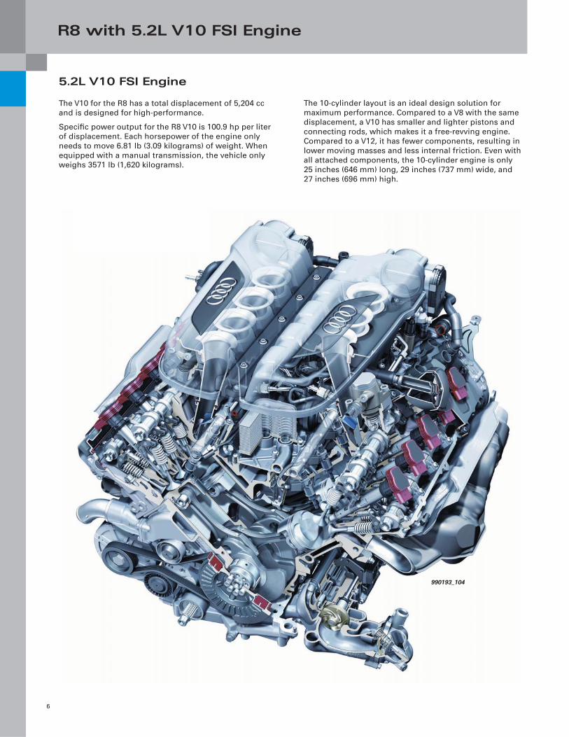
5.2L V10 FSI Engine
The V10 for the R8 has a total displacement of 5,204 cc
and is designed for high-performance.
Specifi c power output for the R8 V10 is 100.9 hp per liter
of displacement. Each horsepower of the engine only
needs to move 6.81 lb (3.09 kilograms) of weight. When
equipped with a manual transmission, the vehicle only
weighs 3571 lb (1,620 kilograms).
The 10-cylinder layout is an ideal design solution for
maximum performance. Compared to a V8 with the same
displacement, a V10 has smaller and lighter pistons and
connecting rods, which makes it a free-revving engine.
Compared to a V12, it has fewer components, resulting in
lower moving masses and less internal friction. Even with
all attached components, the 10-cylinder engine is only
25 inches (646 mm) long, 29 inches (737 mm) wide, and
27 inches (696 mm) high.
990193_104
R8 with 5.2L V10 FSI Engine
7
Specifi cations
990193_113
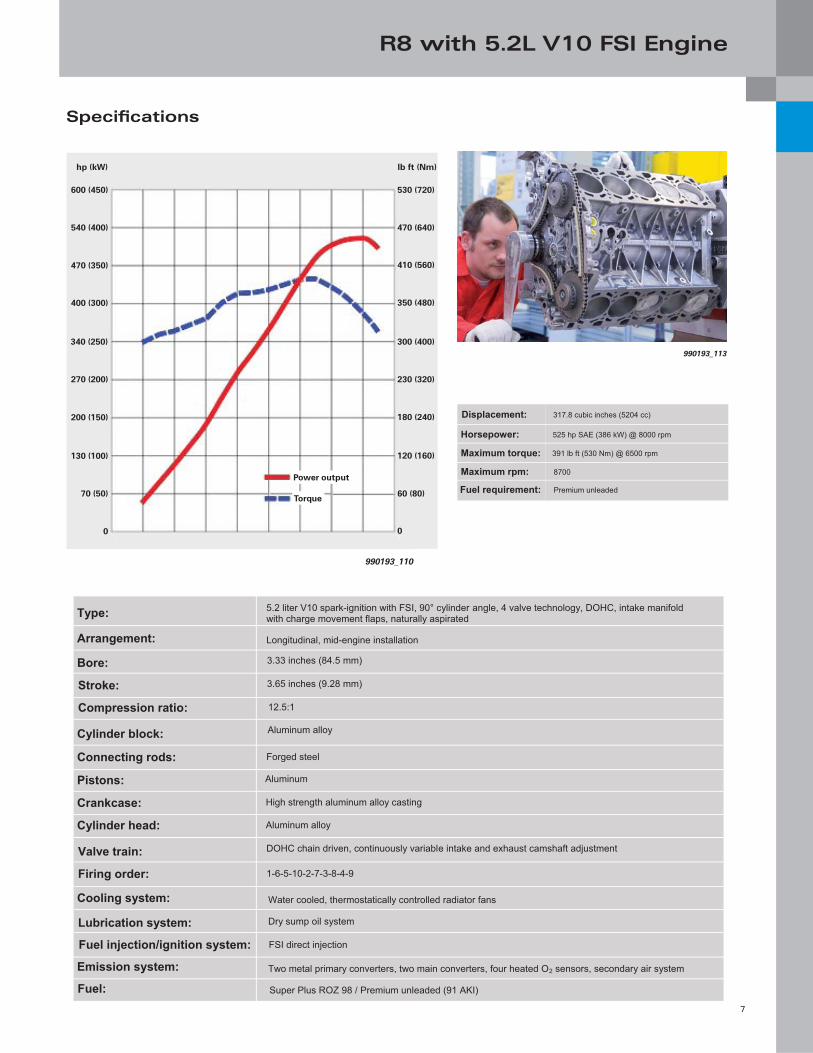
Maximum rpm:
Displacement:
Fuel requirement:
Horsepower:
Maximum torque:
317.8 cubic inches (5204 cc)
525 hp SAE (386 kW) @ 8000 rpm
391 lb ft (530 Nm) @ 6500 rpm
8700
Premium unleaded
Type:
Arrangement:
Bore:
Stroke:
Compression ratio:
Cylinder block:
Connecting rods:
Pistons:
Crankcase:
Cylinder head:
Valve train:
Firing order:
Cooling system:
Lubrication system:
Fuel injection/ignition system:
Emission system:
Fuel:
5.2 liter V10 spark-ignition with FSI, 90° cylinder angle, 4 valve technology, DOHC, intake manifold with charge movement flaps, naturally aspirated
Longitudinal, mid-engine installation
3.33 inches (84.5 mm)
3.65 inches (9.28 mm)
12.5:1
Aluminum alloy
Forged steel
Aluminum
High strength aluminum alloy casting
Aluminum alloy
DOHC chain driven, continuously variable intake and exhaust camshaft adjustment
1-6-5-10-2-7-3-8-4-9
Water cooled, thermostatically controlled radiator fans
Dry sump oil system
FSI direct injection
Two metal primary converters, two main converters, four heated O2 sensors, secondary air system
Super Plus ROZ 98 / Premium unleaded (91 AKI)
990193_110
600 (450)
540 (400)
470 (350)
400 (300)
340 (250)
270 (200)
200 (150)
130 (100)
70 (50)
0
530 (720)
470 (640)
410 (560)
350 (480)
300 (400)
230 (320)
180 (240)
120 (160)
60 (80)
0
hp (kW) lb ft (Nm)
Power output
Torque
R8 with 5.2L V10 FSI Engine
8
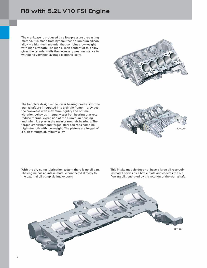
The crankcase is produced by a low-pressure die-casting
method. It is made from hypereutectic aluminum-silicon
alloy — a high-tech material that combines low weight
with high strength. The high silicon content of this alloy
gives the cylinder walls the necessary wear resistance to
withstand very high average piston velocity.
This intake module does not have a large oil reservoir.
Instead it serves as a baffl e plate and collects the out-
fl owing oil generated by the rotation of the crankshaft.
With the dry-sump lubrication system there is no oil pan.
The engine has an intake module connected directly to
the external oil pump via intake ports.
The bedplate design — the lower bearing brackets for the
crankshaft are integrated into a single frame — provides
the crankcase with maximum rigidity and optimal
vibration behavior. Integrally cast iron bearing brackets
reduce thermal expansion of the aluminum housing
and minimize play in the main crankshaft bearings. The
forged crankshaft and forged-steel con rods combine
high strength with low weight. The pistons are forged of
a high-strength aluminum alloy.431_046
431_074
R8 with 5.2L V10 FSI Engine
9
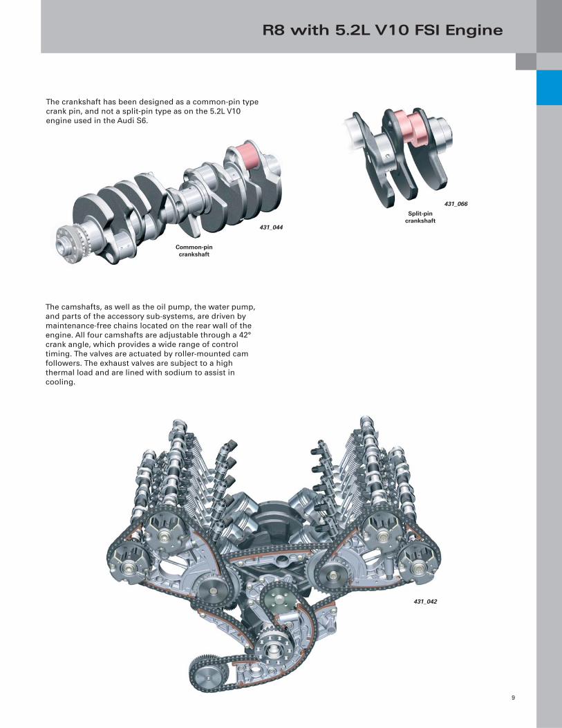
The crankshaft has been designed as a common-pin type
crank pin, and not a split-pin type as on the 5.2L V10
engine used in the Audi S6.
The camshafts, as well as the oil pump, the water pump,
and parts of the accessory sub-systems, are driven by
maintenance-free chains located on the rear wall of the
engine. All four camshafts are adjustable through a 42°
crank angle, which provides a wide range of control
timing. The valves are actuated by roller-mounted cam
followers. The exhaust valves are subject to a high
thermal load and are lined with sodium to assist in
cooling.
Split-pin crankshaft
431_066
Common-pin crankshaft
431_044
431_042
R8 with 5.2L V10 FSI Engine
10
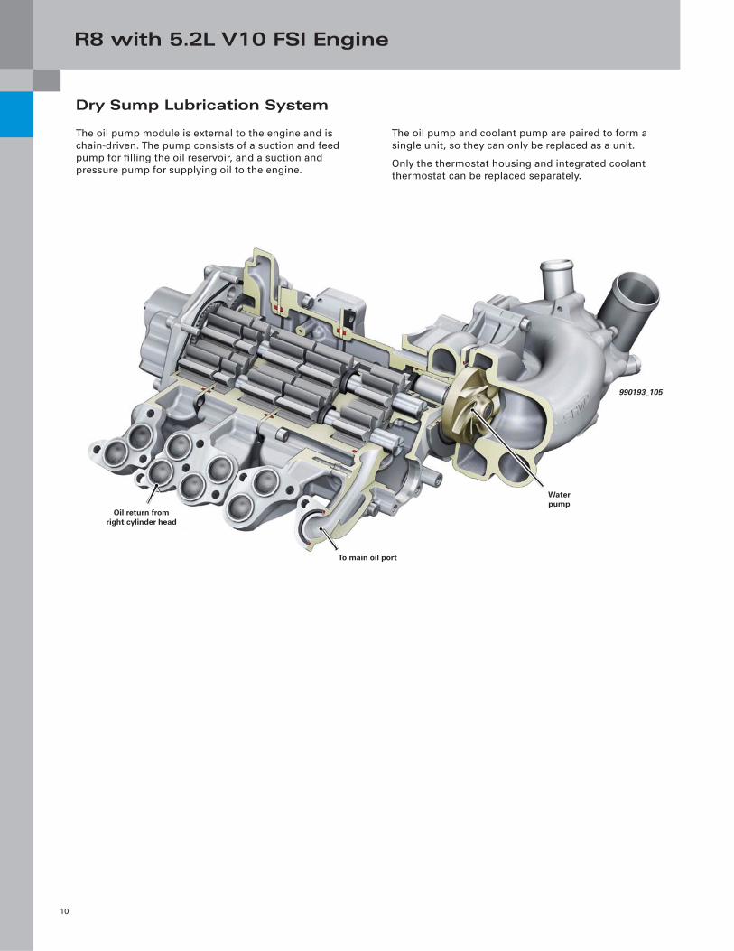
Dry Sump Lubrication System
The oil pump module is external to the engine and is
chain-driven. The pump consists of a suction and feed
pump for fi lling the oil reservoir, and a suction and
pressure pump for supplying oil to the engine.
The oil pump and coolant pump are paired to form a
single unit, so they can only be replaced as a unit.
Only the thermostat housing and integrated coolant
thermostat can be replaced separately.
To main oil port
Water pump
Oil return from right cylinder head
990193_105
R8 with 5.2L V10 FSI Engine
11
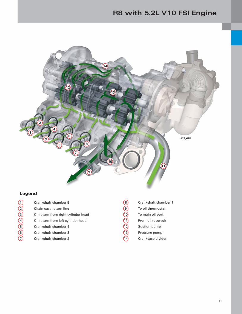
8 Crankshaft chamber 1
9 To oil thermostat
10 To main oil port
11 From oil reservoir
12 Suction pump
13 Pressure pump
14 Crankcase divider
Legend
1 Crankshaft chamber 5
2 Chain case return line
3 Oil return from right cylinder head
4 Oil return from left cylinder head
5 Crankshaft chamber 4
6 Crankshaft chamber 3
7 Crankshaft chamber 2
14
1213
10
9
8
7
6
5
4
3
2
1
11
431_025
R8 with 5.2L V10 FSI Engine
12
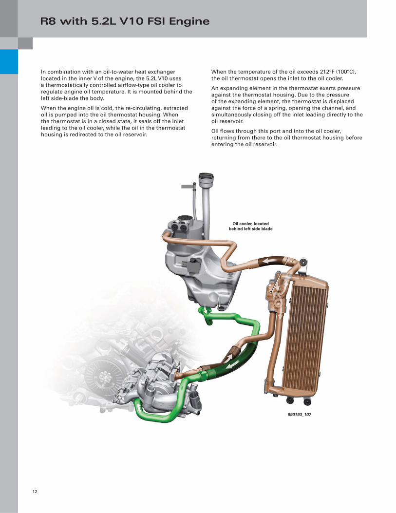
In combination with an oil-to-water heat exchanger
located in the inner V of the engine, the 5.2L V10 uses
a thermostatically controlled airfl ow-type oil cooler to
regulate engine oil temperature. It is mounted behind the
left side-blade the body.
When the engine oil is cold, the re-circulating, extracted
oil is pumped into the oil thermostat housing. When
the thermostat is in a closed state, it seals off the inlet
leading to the oil cooler, while the oil in the thermostat
housing is redirected to the oil reservoir.
When the temperature of the oil exceeds 212°F (100°C),
the oil thermostat opens the inlet to the oil cooler.
An expanding element in the thermostat exerts pressure
against the thermostat housing. Due to the pressure
of the expanding element, the thermostat is displaced
against the force of a spring, opening the channel, and
simultaneously closing off the inlet leading directly to the
oil reservoir.
Oil fl ows through this port and into the oil cooler,
returning from there to the oil thermostat housing before
entering the oil reservoir.
990193_107
Oil cooler, located behind left side blade

Notes
13
R8 with 5.2L V10 FSI Engine
14
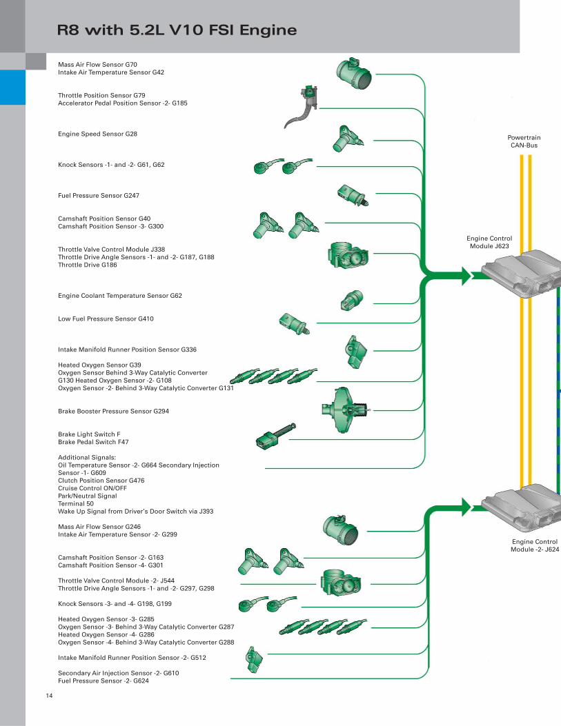
Mass Air Flow Sensor G70
Intake Air Temperature Sensor G42
Throttle Position Sensor G79
Accelerator Pedal Position Sensor -2- G185
Engine Speed Sensor G28
Knock Sensors -1- and -2- G61, G62
Fuel Pressure Sensor G247
Camshaft Position Sensor G40
Camshaft Position Sensor -3- G300
Throttle Valve Control Module J338
Throttle Drive Angle Sensors -1- and -2- G187, G188
Throttle Drive G186
Engine Coolant Temperature Sensor G62
Low Fuel Pressure Sensor G410
Intake Manifold Runner Position Sensor G336
Heated Oxygen Sensor G39
Oxygen Sensor Behind 3-Way Catalytic Converter
G130 Heated Oxygen Sensor -2- G108
Oxygen Sensor -2- Behind 3-Way Catalytic Converter G131
Brake Booster Pressure Sensor G294
Brake Light Switch F
Brake Pedal Switch F47
Additional Signals:
Oil Temperature Sensor -2- G664 Secondary Injection
Sensor -1- G609
Clutch Position Sensor G476
Cruise Control ON/OFF
Park/Neutral Signal
Terminal 50
Wake Up Signal from Driver’s Door Switch via J393
Mass Air Flow Sensor G246
Intake Air Temperature Sensor -2- G299
Camshaft Position Sensor -2- G163
Camshaft Position Sensor -4- G301
Throttle Valve Control Module -2- J544
Throttle Drive Angle Sensors -1- and -2- G297, G298
Knock Sensors -3- and -4- G198, G199
Heated Oxygen Sensor -3- G285
Oxygen Sensor -3- Behind 3-Way Catalytic Converter G287
Heated Oxygen Sensor -4- G286
Oxygen Sensor -4- Behind 3-Way Catalytic Converter G288
Intake Manifold Runner Position Sensor -2- G512
Secondary Air Injection Sensor -2- G610
Fuel Pressure Sensor -2- G624
Powertrain
CAN-Bus
Engine Control
Module J623
Engine Control
Module -2- J624
R8 with 5.2L V10 FSI Engine
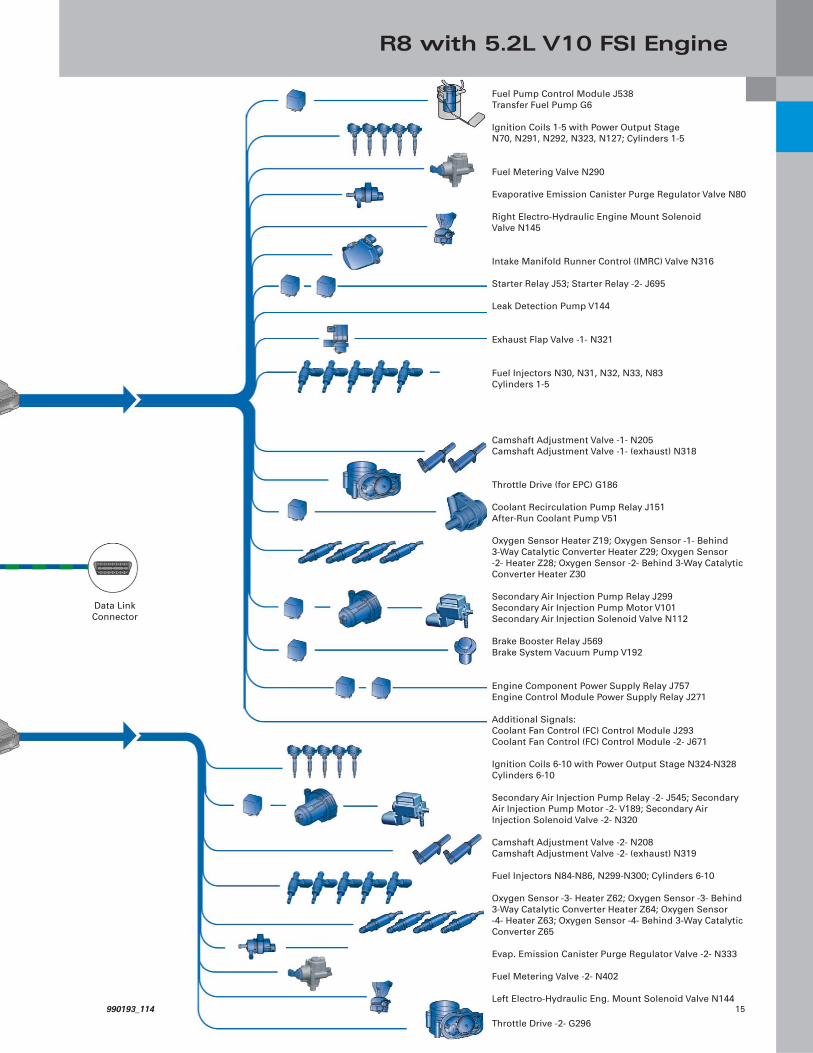
15
Fuel Pump Control Module J538
Transfer Fuel Pump G6
Ignition Coils 1-5 with Power Output Stage
N70, N291, N292, N323, N127; Cylinders 1-5
Fuel Metering Valve N290
Evaporative Emission Canister Purge Regulator Valve N80
Right Electro-Hydraulic Engine Mount Solenoid
Valve N145
Intake Manifold Runner Control (IMRC) Valve N316
Starter Relay J53; Starter Relay -2- J695
Leak Detection Pump V144
Exhaust Flap Valve -1- N321
Fuel Injectors N30, N31, N32, N33, N83
Cylinders 1-5
Camshaft Adjustment Valve -1- N205
Camshaft Adjustment Valve -1- (exhaust) N318
Throttle Drive (for EPC) G186
Coolant Recirculation Pump Relay J151
After-Run Coolant Pump V51
Oxygen Sensor Heater Z19; Oxygen Sensor -1- Behind
3-Way Catalytic Converter Heater Z29; Oxygen Sensor
-2- Heater Z28; Oxygen Sensor -2- Behind 3-Way Catalytic
Converter Heater Z30
Secondary Air Injection Pump Relay J299
Secondary Air Injection Pump Motor V101
Secondary Air Injection Solenoid Valve N112
Brake Booster Relay J569
Brake System Vacuum Pump V192
Engine Component Power Supply Relay J757
Engine Control Module Power Supply Relay J271
Additional Signals:
Coolant Fan Control (FC) Control Module J293
Coolant Fan Control (FC) Control Module -2- J671
Ignition Coils 6-10 with Power Output Stage N324-N328
Cylinders 6-10
Secondary Air Injection Pump Relay -2- J545; Secondary
Air Injection Pump Motor -2- V189; Secondary Air
Injection Solenoid Valve -2- N320
Camshaft Adjustment Valve -2- N208
Camshaft Adjustment Valve -2- (exhaust) N319
Fuel Injectors N84-N86, N299-N300; Cylinders 6-10
Oxygen Sensor -3- Heater Z62; Oxygen Sensor -3- Behind
3-Way Catalytic Converter Heater Z64; Oxygen Sensor
-4- Heater Z63; Oxygen Sensor -4- Behind 3-Way Catalytic
Converter Z65
Evap. Emission Canister Purge Regulator Valve -2- N333
Fuel Metering Valve -2- N402
Left Electro-Hydraulic Eng. Mount Solenoid Valve N144
Throttle Drive -2- G296
Data Link
Connector
990193_114
R8 with 5.2L V10 FSI Engine
16
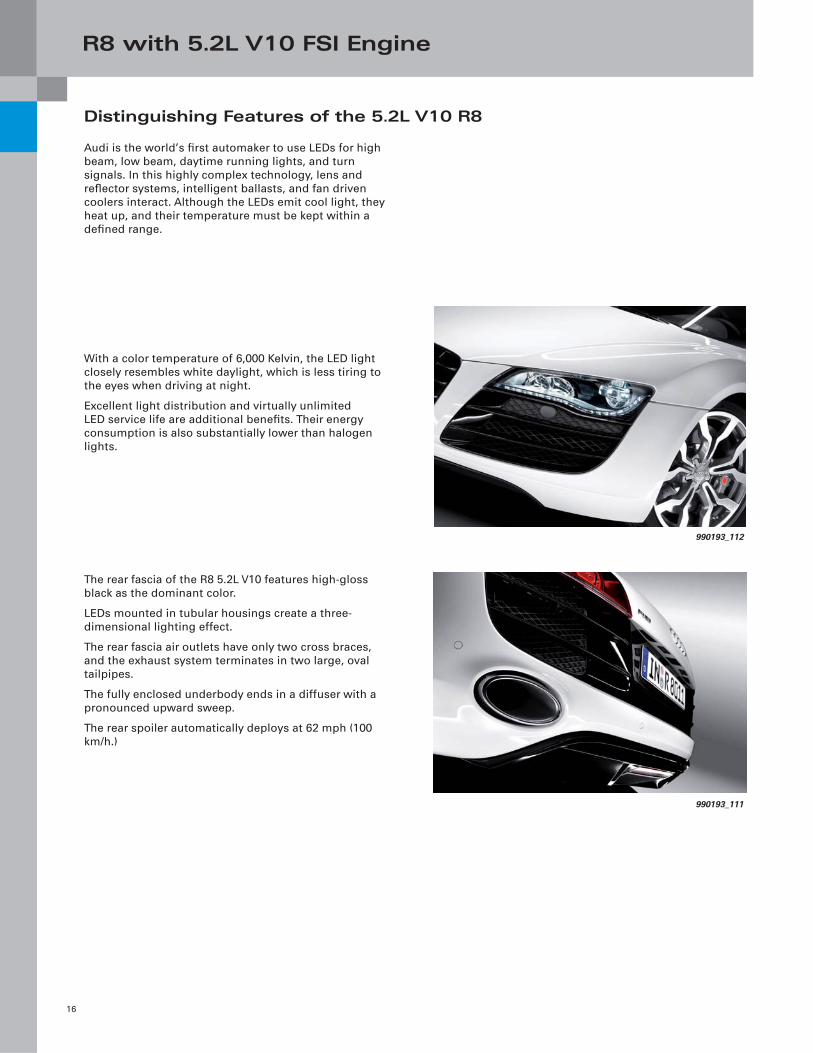
Distinguishing Features of the 5.2L V10 R8
The rear fascia of the R8 5.2L V10 features high-gloss
black as the dominant color.
LEDs mounted in tubular housings create a three-
dimensional lighting effect.
The rear fascia air outlets have only two cross braces,
and the exhaust system terminates in two large, oval
tailpipes.
The fully enclosed underbody ends in a diffuser with a
pronounced upward sweep.
The rear spoiler automatically deploys at 62 mph (100
km/h.)
With a color temperature of 6,000 Kelvin, the LED light
closely resembles white daylight, which is less tiring to
the eyes when driving at night.
Excellent light distribution and virtually unlimited
LED service life are additional benefi ts. Their energy
consumption is also substantially lower than halogen
lights.
Audi is the world’s fi rst automaker to use LEDs for high
beam, low beam, daytime running lights, and turn
signals. In this highly complex technology, lens and
refl ector systems, intelligent ballasts, and fan driven
coolers interact. Although the LEDs emit cool light, they
heat up, and their temperature must be kept within a
defi ned range.
990193_112
990193_111
Packaged Ultrasonic Level Sensor (PULS)
17
New Oil Level Sensor
A new generation engine oil level sensing system has
been introduced by Audi. It is referred to in the technical
literature and VAS Scan Tool as: PULS — Packaged
Ultrasonic Level Sensor. Vehicles using this system can
be identifi ed by the absence of an oil dipstick.
PULS operates on an ultrasonic principle. Ultrasound
pulses generated by the oil level sensor are refl ected
by the oil-air boundary layer. This type of level sensor
replaces the older Thermal Oil Level Sensor (TOLS) that
used the hot-wire principle.
Ultrasonic signals are processed electronically by
circuitry in the oil level sensor and are transmitted to
the instrument cluster through a Pulse Width Modulated
(PWM) signal.
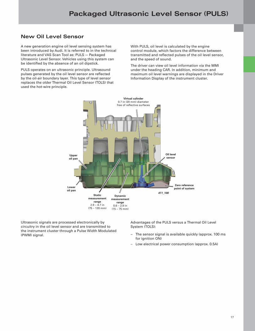
411_100
Virtual cylinder0.7 in (20 mm) diameter
free of refl ective surfaces
Upper oil pan
Oil level sensor
Static measurement
range2.9 – 4.7 in
(75 – 120 mm)
Dynamic measurement
range0.6 – 2.9 in
(15 – 75 mm)
Zero reference point of systemLower
oil pan
With PULS, oil level is calculated by the engine
control module, which factors the difference between
transmitted and refl ected pulses of the oil level sensor,
and the speed of sound.
The driver can view oil level information via the MMI
under the heading CAR. In addition, minimum and
maximum oil level warnings are displayed in the Driver
Information Display of the instrument cluster.
Advantages of the PULS versus a Thermal Oil Level
System (TOLS):
– The sensor signal is available quickly (approx. 100 ms
for ignition ON)
– Low electrical power consumption (approx. 0.5A)
Packaged Ultrasonic Level Sensor (PULS)
18
Oil Level Scale
The Engine Control Module calculates oil level in the
engine. This information is transmitted to the Powertrain
CAN-bus where it is read by the instrument cluster and
MMI, which then pass this information on to other sub-
systems via Data Bus On Board Diagnostic Interface J533.
Because the dipstick has been eliminated, the customer
can only check the oil level via the instrument cluster or
MMI displays.
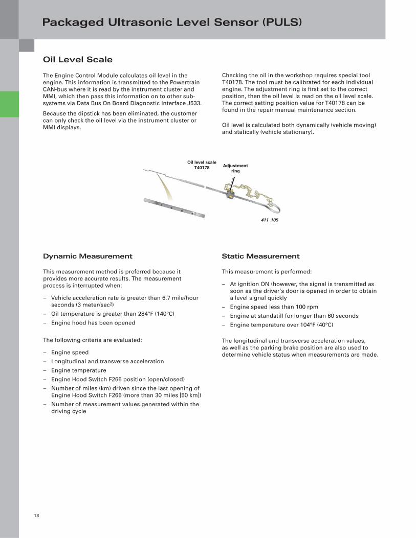
Checking the oil in the workshop requires special tool
T40178. The tool must be calibrated for each individual
engine. The adjustment ring is fi rst set to the correct
position, then the oil level is read on the oil level scale.
The correct setting position value for T40178 can be
found in the repair manual maintenance section.
Oil level is calculated both dynamically (vehicle moving)
and statically (vehicle stationary).
Dynamic Measurement
This measurement method is preferred because it
provides more accurate results. The measurement
process is interrupted when:
– Vehicle acceleration rate is greater than 6.7 mile/hour
seconds (3 meter/sec2)
– Oil temperature is greater than 284°F (140°C)
– Engine hood has been opened
The following criteria are evaluated:
– Engine speed
– Longitudinal and transverse acceleration
– Engine temperature
– Engine Hood Switch F266 position (open/closed)
– Number of miles (km) driven since the last opening of
Engine Hood Switch F266 (more than 30 miles [50 km])
– Number of measurement values generated within the
driving cycle
Static Measurement
This measurement is performed:
– At ignition ON (however, the signal is transmitted as
soon as the driver’s door is opened in order to obtain
a level signal quickly
– Engine speed less than 100 rpm
– Engine at standstill for longer than 60 seconds
– Engine temperature over 104°F (40°C)
The longitudinal and transverse acceleration values,
as well as the parking brake position are also used to
determine vehicle status when measurements are made.
Oil level scale T40178 Adjustment
ring
411_105
Packaged Ultrasonic Level Sensor (PULS)
19
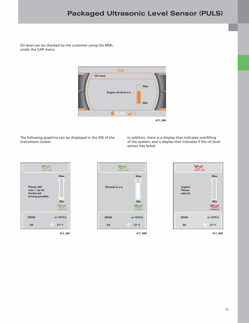
Oil level can be checked by the customer using the MMI,
under the CAR menu.
The following graphics can be displayed in the DIS of the
instrument cluster.
In addition, there is a display that indicates overfi lling
of the system, and a display that indicates if the oil level
sensor has failed.
Oil Level
Engine oil level o.k.
Max
Min
411_096
Please add max. 1 qt oil. Continued driving possible.
m 1975.535540
Max
D4 27° F
Min
411_097 411_098
Oil level is o.k.
m 1975.535540
Max
D4 27° F
Min
411_099
Urgent: Please add oil.
m 1975.535540
Max
D4 27° F
Min
0B5 S Tronic Transmission
20
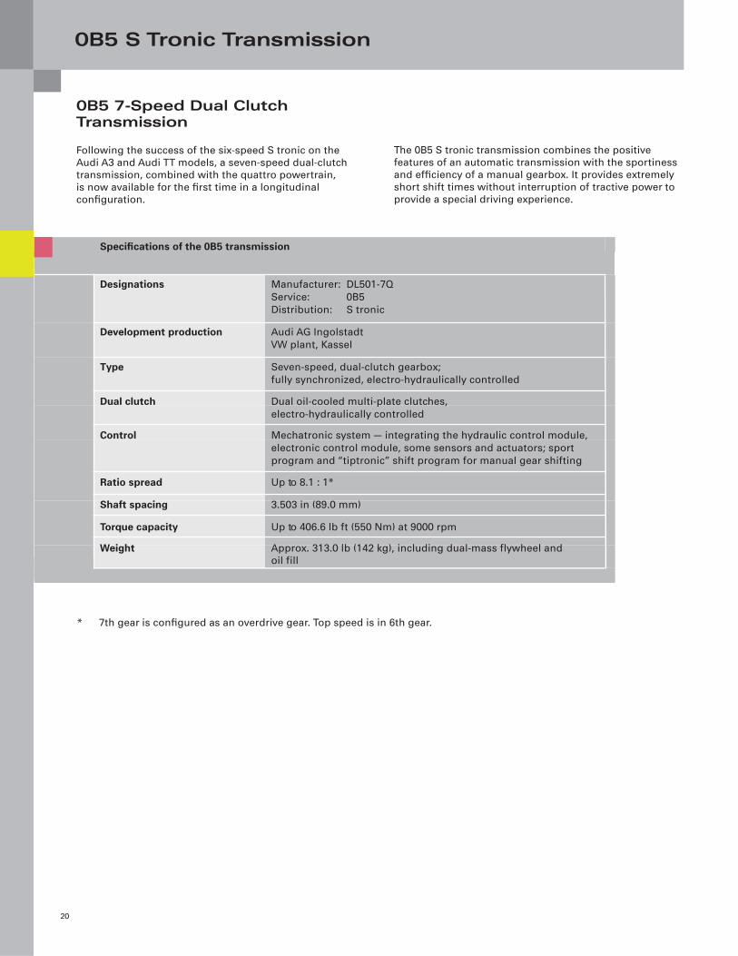
0B5 7-Speed Dual Clutch Transmission
Following the success of the six-speed S tronic on the
Audi A3 and Audi TT models, a seven-speed dual-clutch
transmission, combined with the quattro powertrain,
is now available for the fi rst time in a longitudinal
confi guration.
The 0B5 S tronic transmission combines the positive
features of an automatic transmission with the sportiness
and effi ciency of a manual gearbox. It provides extremely
short shift times without interruption of tractive power to
provide a special driving experience.
* 7th gear is confi gured as an overdrive gear. Top speed is in 6th gear.
Specifications of the 0B5 transmission
Designations Manufacturer: DL501-7Q
Service: 0B5
Distribution: S tronic
Development production Audi AG Ingolstadt
VW plant, Kassel
Type Seven-speed, dual-clutch gearbox;
fully synchronized, electro-hydraulically controlled
Dual clutch Dual oil-cooled multi-plate clutches,
electro-hydraulically controlled
Control Mechatronic system — integrating the hydraulic control module,
electronic control module, some sensors and actuators; sport
program and “tiptronic” shift program for manual gear shifting
Ratio spread Up to 8.1 : 1*
Shaft spacing 3.503 in (89.0 mm)
Torque capacity Up to 406.6 lb ft (550 Nm) at 9000 rpm
Weight Approx. 313.0 lb (142 kg), including dual-mass flywheel and
oil fill
0B5 S Tronic Transmission
21
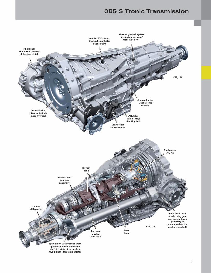
Transmission plate with dual-mass fl ywheel ATF, fi ller
and oil level checking bolt
Connection for Mechatronic
module
Connection to ATF cooler
Vent for gear oil system (gears/transfer case/
front axle drive)Vent for ATF system (hydraulic controls/
dual clutch)
Final drive/differential (forward of the dual clutch)
429_124
Spur pinion with special tooth geometry which allows the
shaft to rotate at an angle in two planes (beveloid gearing)
Gear lever
Final drive with welded ring gear and special tooth
geometry to accommodate the angled side shaft
Bi-planar angled
side shaft
Dual clutch (K1, K2)
Oil drip pans
Seven-speed gearbox
assembly
Center differential
429_128
0B5 S Tronic Transmission
22
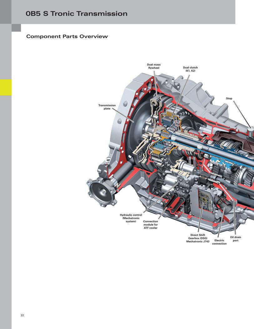
Component Parts Overview
Direct Shift Gearbox (DSG)
Mechatronic J743
Dual clutch (K1, K2)
Connection module for ATF cooler
Dual mass fl ywheel
Transmission plate
Hydraulic control (Mechatronic
system)
Electric connection
Oil drain port
Stop
0B5 S Tronic Transmission
23
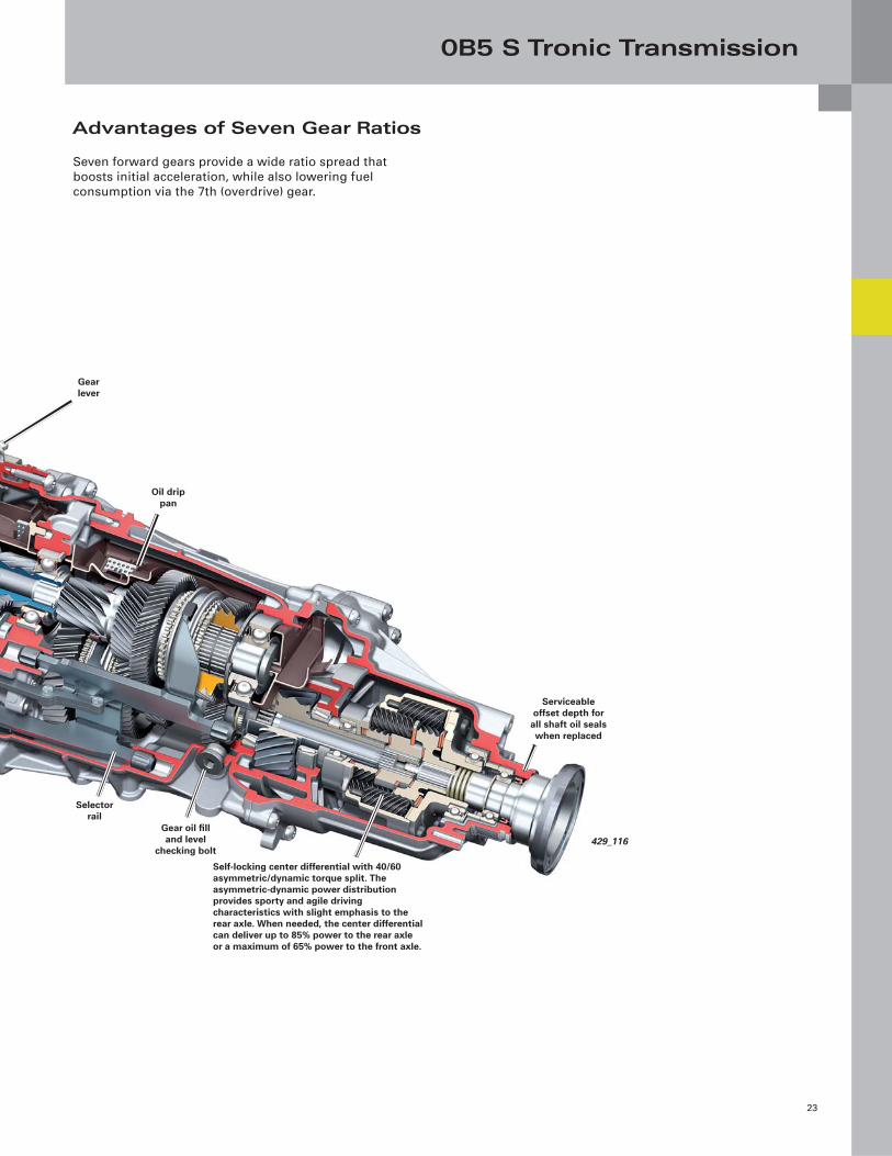
Advantages of Seven Gear Ratios
Self-locking center differential with 40/60 asymmetric/dynamic torque split. The asymmetric-dynamic power distribution provides sporty and agile driving characteristics with slight emphasis to the rear axle. When needed, the center differential can deliver up to 85% power to the rear axle or a maximum of 65% power to the front axle.
Selector rail
Serviceable offset depth for
all shaft oil seals when replaced
Gear oil fi ll and level
checking bolt
Gear lever
Oil drip pan
429_116
Seven forward gears provide a wide ratio spread that
boosts initial acceleration, while also lowering fuel
consumption via the 7th (overdrive) gear.
0B5 S Tronic Transmission
24
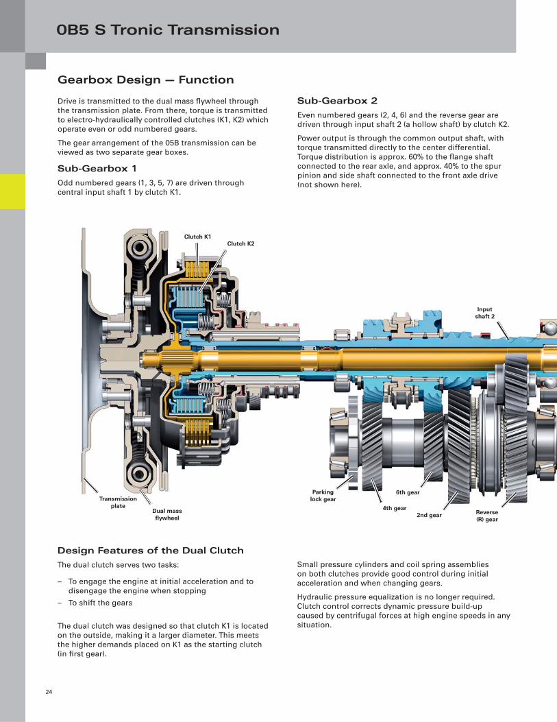
Gearbox Design — Function
Drive is transmitted to the dual mass fl ywheel through
the transmission plate. From there, torque is transmitted
to electro-hydraulically controlled clutches (K1, K2) which
operate even or odd numbered gears.
The gear arrangement of the 05B transmission can be
viewed as two separate gear boxes.
Sub-Gearbox 1
Odd numbered gears (1, 3, 5, 7) are driven through
central input shaft 1 by clutch K1.
Sub-Gearbox 2
Even numbered gears (2, 4, 6) and the reverse gear are
driven through input shaft 2 (a hollow shaft) by clutch K2.
Power output is through the common output shaft, with
torque transmitted directly to the center differential.
Torque distribution is approx. 60% to the fl ange shaft
connected to the rear axle, and approx. 40% to the spur
pinion and side shaft connected to the front axle drive
(not shown here).
Design Features of the Dual Clutch
The dual clutch serves two tasks:
– To engage the engine at initial acceleration and to
disengage the engine when stopping
– To shift the gears
The dual clutch was designed so that clutch K1 is located
on the outside, making it a larger diameter. This meets
the higher demands placed on K1 as the starting clutch
(in fi rst gear).
Small pressure cylinders and coil spring assemblies
on both clutches provide good control during initial
acceleration and when changing gears.
Hydraulic pressure equalization is no longer required.
Clutch control corrects dynamic pressure build-up
caused by centrifugal forces at high engine speeds in any
situation.
Clutch K2
6th gear
4th gear
Clutch K1
Input shaft 2
Dual mass fl ywheel
Parking lock gearTransmission
plate
2nd gear Reverse (R) gear
0B5 S Tronic Transmission
25
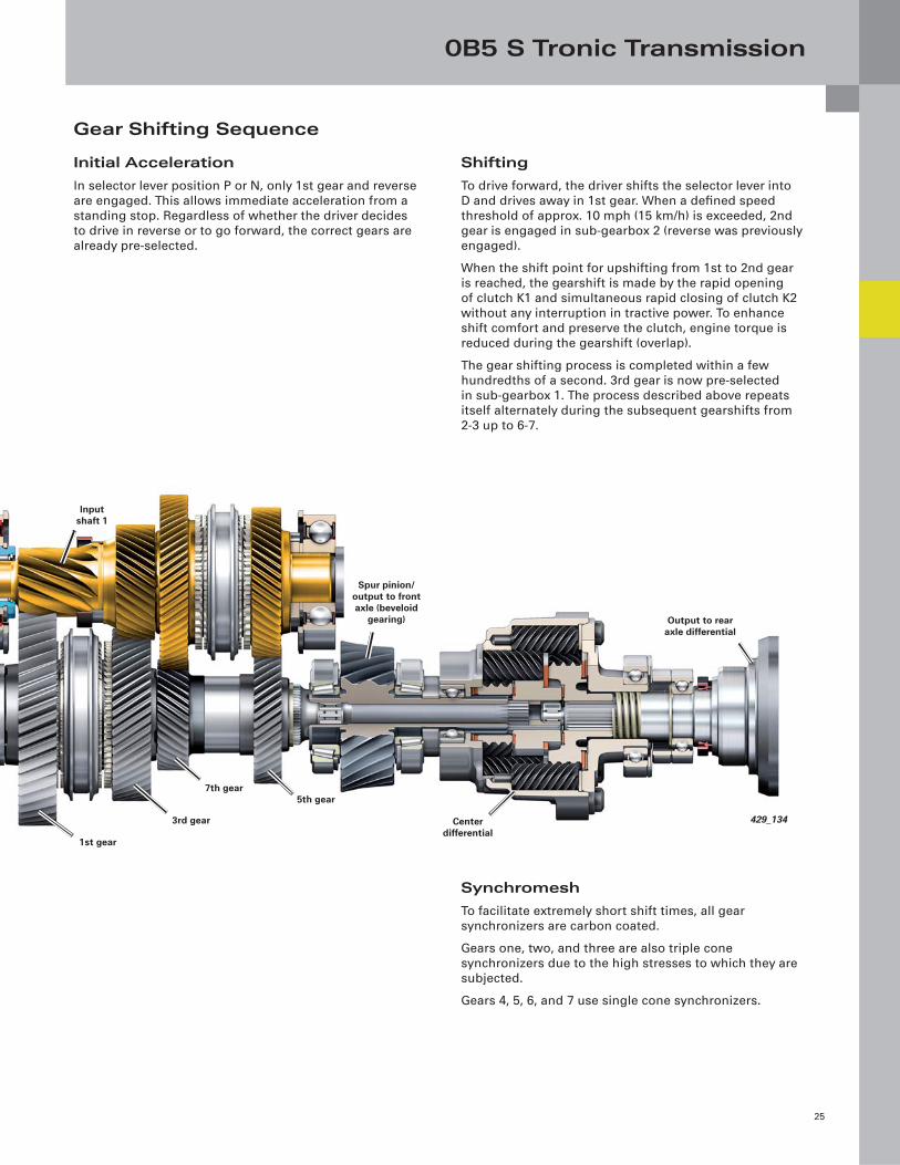
Gear Shifting Sequence
Synchromesh
To facilitate extremely short shift times, all gear
synchronizers are carbon coated.
Gears one, two, and three are also triple cone
synchronizers due to the high stresses to which they are
subjected.
Gears 4, 5, 6, and 7 use single cone synchronizers.
Initial Acceleration
In selector lever position P or N, only 1st gear and reverse
are engaged. This allows immediate acceleration from a
standing stop. Regardless of whether the driver decides
to drive in reverse or to go forward, the correct gears are
already pre-selected.
Spur pinion/output to front axle (beveloid
gearing) Output to rear axle differential
Input shaft 1
7th gear5th gear
1st gear
3rd gear Center differential
429_134
Shifting
To drive forward, the driver shifts the selector lever into
D and drives away in 1st gear. When a defi ned speed
threshold of approx. 10 mph (15 km/h) is exceeded, 2nd
gear is engaged in sub-gearbox 2 (reverse was previously
engaged).
When the shift point for upshifting from 1st to 2nd gear
is reached, the gearshift is made by the rapid opening
of clutch K1 and simultaneous rapid closing of clutch K2
without any interruption in tractive power. To enhance
shift comfort and preserve the clutch, engine torque is
reduced during the gearshift (overlap).
The gear shifting process is completed within a few
hundredths of a second. 3rd gear is now pre-selected
in sub-gearbox 1. The process described above repeats
itself alternately during the subsequent gearshifts from
2-3 up to 6-7.
0B5 S Tronic Transmission
26
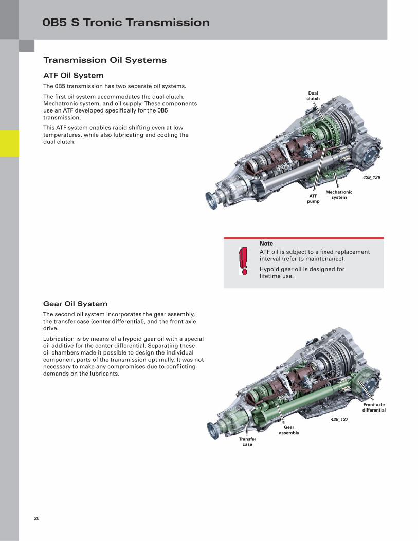
Transmission Oil Systems
ATF Oil System
The 0B5 transmission has two separate oil systems.
The fi rst oil system accommodates the dual clutch,
Mechatronic system, and oil supply. These components
use an ATF developed specifi cally for the 0B5
transmission.
This ATF system enables rapid shifting even at low
temperatures, while also lubricating and cooling the
dual clutch.
Gear Oil System
The second oil system incorporates the gear assembly,
the transfer case (center differential), and the front axle
drive.
Lubrication is by means of a hypoid gear oil with a special
oil additive for the center differential. Separating these
oil chambers made it possible to design the individual
component parts of the transmission optimally. It was not
necessary to make any compromises due to confl icting
demands on the lubricants.
NoteATF oil is subject to a fi xed replacement
interval (refer to maintenance).
Hypoid gear oil is designed for
lifetime use.
Mechatronic system
Dual clutch
ATF pump
429_126
Transfer case
Front axle differential
Gear assembly
429_127
0B5 S Tronic Transmission
27
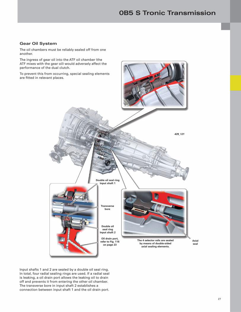
Double oil seal ring
Input shaft 2
Oil drain port, refer to Fig. 116
on page 23
Transverse bore
Double oil seal ring Input shaft 1
The 4 selector rails are sealed by means of double-sided
axial sealing elements.
Axial seal
429_121
Input shafts 1 and 2 are sealed by a double oil seal ring.
In total, four radial sealing rings are used. If a radial seal
is leaking, a oil drain port allows the leaking oil to drain
off and prevents it from entering the other oil chamber.
The transverse bore in input shaft 2 establishes a
connection between input shaft 1 and the oil drain port.
Gear Oil System
The oil chambers must be reliably sealed off from one
another.
The ingress of gear oil into the ATF oil chamber (the
ATF mixes with the gear oil) would adversely affect the
performance of the dual clutch.
To prevent this from occurring, special sealing elements
are fi tted in relevant places.
0B5 S Tronic Transmission
28
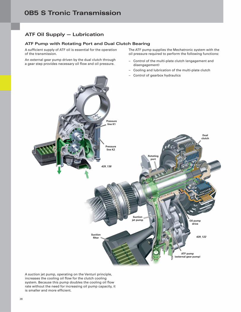
Suction fi lter
Rotating port
Dual clutch
Suction jet pump Oil pump
drive
ATF pump(external gear pump)
429_122
A suction jet pump, operating on the Venturi principle,
increases the cooling oil fl ow for the clutch cooling
system. Because this pump doubles the cooling oil fl ow
rate without the need for increasing oil pump capacity, it
is smaller and more effi cient.
ATF Oil Supply — Lubrication
The ATF pump supplies the Mechatronic system with the
oil pressure required to perform the following functions:
– Control of the multi-plate clutch (engagement and
disengagement)
– Cooling and lubrication of the multi-plate clutch
– Control of gearbox hydraulics
ATF Pump with Rotating Port and Dual Clutch Bearing
Pressure line K1
Pressure line K2
429_138
A suffi cient supply of ATF oil is essential for the operation
of the transmission.
An external gear pump driven by the dual clutch through
a gear step provides necessary oil fl ow and oil pressure.
0B5 S Tronic Transmission
29
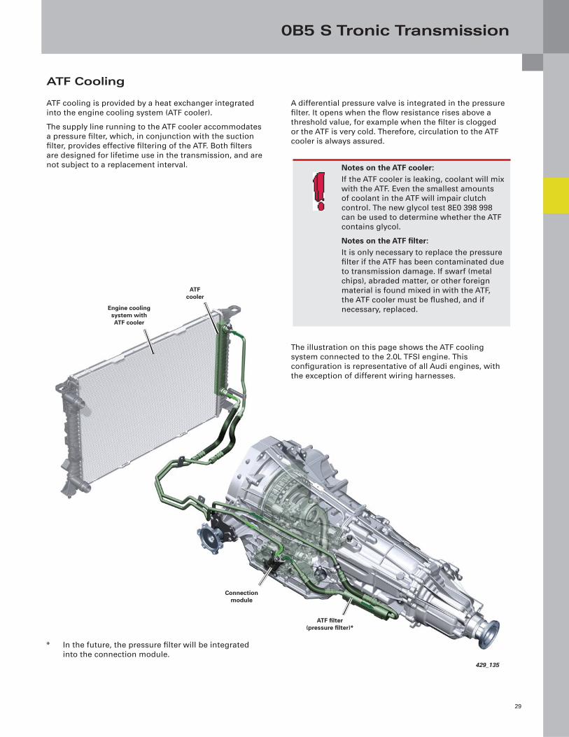
Connection module
ATF fi lter(pressure fi lter)*
ATF cooler
Engine cooling system with ATF cooler
429_135
ATF Cooling
ATF cooling is provided by a heat exchanger integrated
into the engine cooling system (ATF cooler).
The supply line running to the ATF cooler accommodates
a pressure fi lter, which, in conjunction with the suction
fi lter, provides effective fi ltering of the ATF. Both fi lters
are designed for lifetime use in the transmission, and are
not subject to a replacement interval.
A differential pressure valve is integrated in the pressure
fi lter. It opens when the fl ow resistance rises above a
threshold value, for example when the fi lter is clogged
or the ATF is very cold. Therefore, circulation to the ATF
cooler is always assured.
Notes on the ATF cooler:If the ATF cooler is leaking, coolant will mix
with the ATF. Even the smallest amounts
of coolant in the ATF will impair clutch
control. The new glycol test 8E0 398 998
can be used to determine whether the ATF
contains glycol.
Notes on the ATF fi lter:It is only necessary to replace the pressure
fi lter if the ATF has been contaminated due
to transmission damage. If swarf (metal
chips), abraded matter, or other foreign
material is found mixed in with the ATF,
the ATF cooler must be fl ushed, and if
necessary, replaced.
The illustration on this page shows the ATF cooling
system connected to the 2.0L TFSI engine. This
confi guration is representative of all Audi engines, with
the exception of different wiring harnesses.
* In the future, the pressure fi lter will be integrated
into the connection module.
0B5 S Tronic Transmission
30
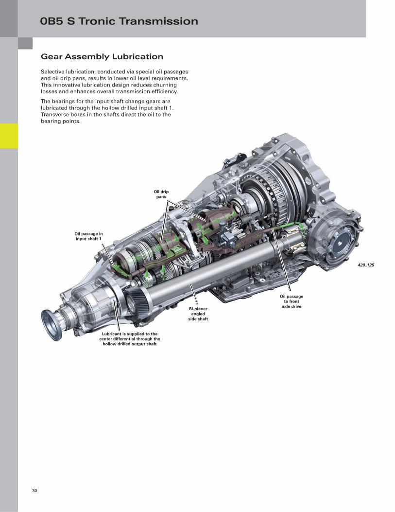
Gear Assembly Lubrication
Selective lubrication, conducted via special oil passages
and oil drip pans, results in lower oil level requirements.
This innovative lubrication design reduces churning
losses and enhances overall transmission effi ciency.
The bearings for the input shaft change gears are
lubricated through the hollow drilled input shaft 1.
Transverse bores in the shafts direct the oil to the
bearing points.
Lubricant is supplied to the center differential through the
hollow drilled output shaft
Oil passage to front
axle driveBi-planar angled
side shaft
Oil drip pans
Oil passage in input shaft 1
429_125
0B5 S Tronic Transmission
31
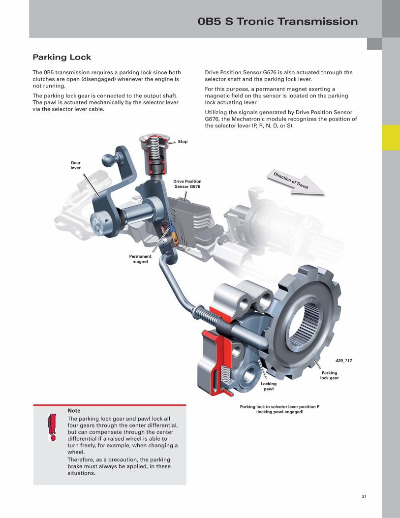
Parking Lock
The 0B5 transmission requires a parking lock since both
clutches are open (disengaged) whenever the engine is
not running.
The parking lock gear is connected to the output shaft.
The pawl is actuated mechanically by the selector lever
via the selector lever cable.
Drive Position Sensor G676 is also actuated through the
selector shaft and the parking lock lever.
For this purpose, a permanent magnet exerting a
magnetic fi eld on the sensor is located on the parking
lock actuating lever.
Utilizing the signals generated by Drive Position Sensor
G676, the Mechatronic module recognizes the position of
the selector lever (P, R, N, D, or S).
Locking pawl
Parking lock gear
429_117
Stop
Drive Position Sensor G676
Direction of Travel
Gear lever
Permanent magnet
Parking lock in selector lever position P (locking pawl engaged)Note
The parking lock gear and pawl lock all
four gears through the center differential,
but can compensate through the center
differential if a raised wheel is able to
turn freely, for example, when changing a
wheel.
Therefore, as a precaution, the parking
brake must always be applied, in these
situations.
0B5 S Tronic Transmission
32
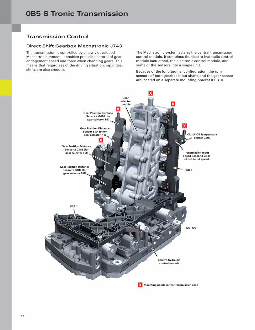
Transmission Control
The Mechatronic system acts as the central transmission
control module. It combines the electro-hydraulic control
module (actuators), the electronic control module, and
some of the sensors into a single unit.
Because of the longitudinal confi guration, the rpm
sensors of both gearbox input shafts and the gear sensor
are located on a separate mounting bracket (PCB 3).
Direct Shift Gearbox Mechatronic J743
The transmission is controlled by a newly developed
Mechatronic system. It enables precision control of gear
engagement speed and force when changing gears. This
means that regardless of the driving situation, rapid gear
shifts are also smooth.
X Mounting points in the transmission case
PCB 1
PCB 2
Transmission Input Speed Sensor 3 G641 (clutch input speed)
Electro-hydraulic control module
Clutch Oil Temperature Sensor G509
Gear selector module
Gear Position Distance Sensor 3 G489 (for gear selector 7-5)
Gear Position Distance Sensor 1 G487 (for gear selector 2-R)
X
XX
X
X
Gear Position Distance Sensor 4 G490 (for gear selector 4-6)
Gear Position Distance Sensor 2 G488 (for gear selector 1-3)
429_133
0B5 S Tronic Transmission
33
Connector: Mechatronic
wiring harness
Transmission Input Speed
Sensor1 G632
Transmission Input Speed Sensor G612
Wiring harness/cable duct
Connector Sensor
module wiring harness
Drive Position Sensor G676
Center differential
XX
X
X
X
XX
Connector: Gearbox Control
Module PCB 2Connector:
Gearbox Control
Module PCB 1
Electronic module
Connector: wiring harness (sensor module)
429_130
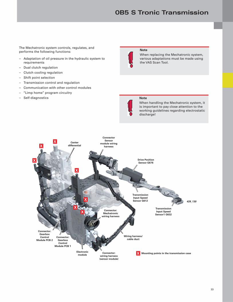
The Mechatronic system controls, regulates, and
performs the following functions:
– Adaptation of oil pressure in the hydraulic system to
requirements
– Dual clutch regulation
– Clutch cooling regulation
– Shift point selection
– Transmission control and regulation
– Communication with other control modules
– “Limp home” program circuitry
– Self-diagnostics
NoteWhen replacing the Mechatronic system,
various adaptations must be made using
the VAS Scan Tool.
NoteWhen handling the Mechatronic system, it
is important to pay close attention to the
working guidelines regarding electrostatic
discharge!
X Mounting points in the transmission case
0B5 S Tronic Transmission
34
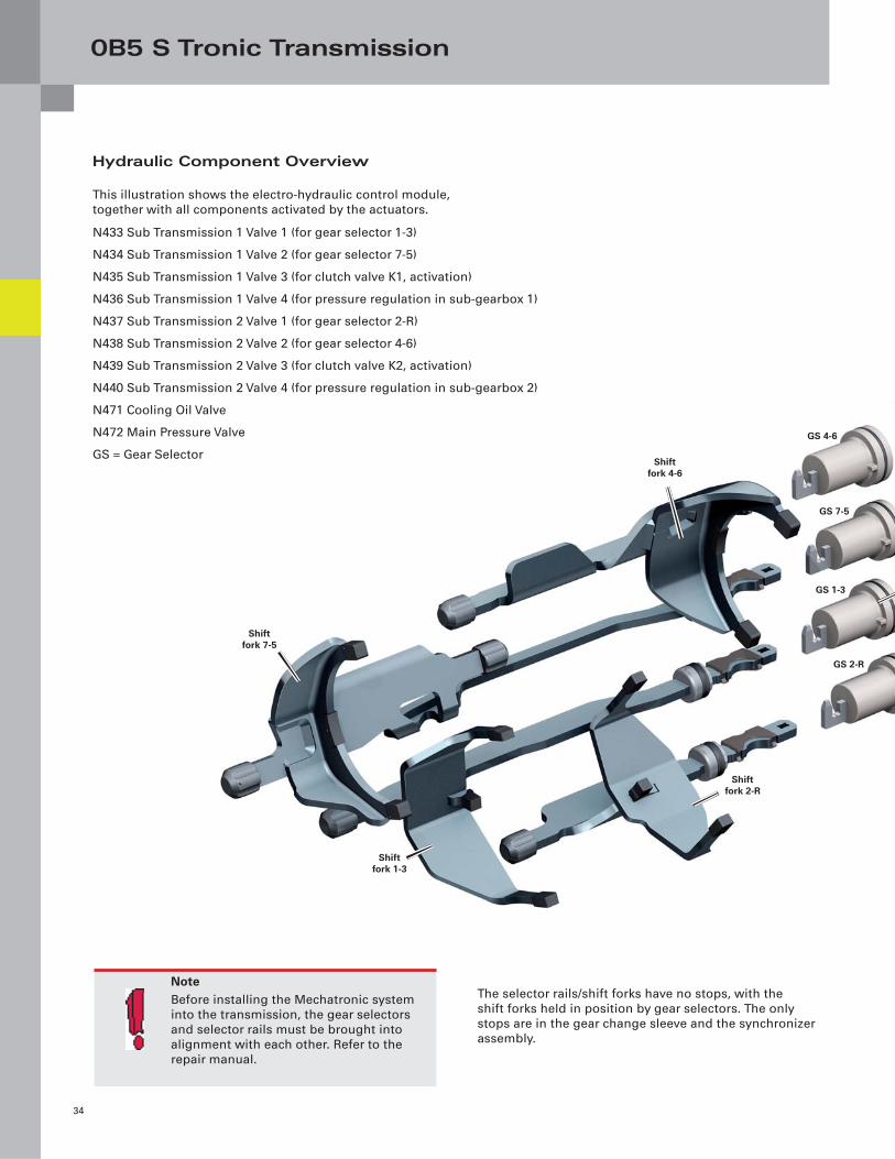
Shift fork 4-6
Shift fork 1-3
Shift fork 7-5
Shift fork 2-R
GS 4-6
GS 7-5
GS 1-3
GS 2-R
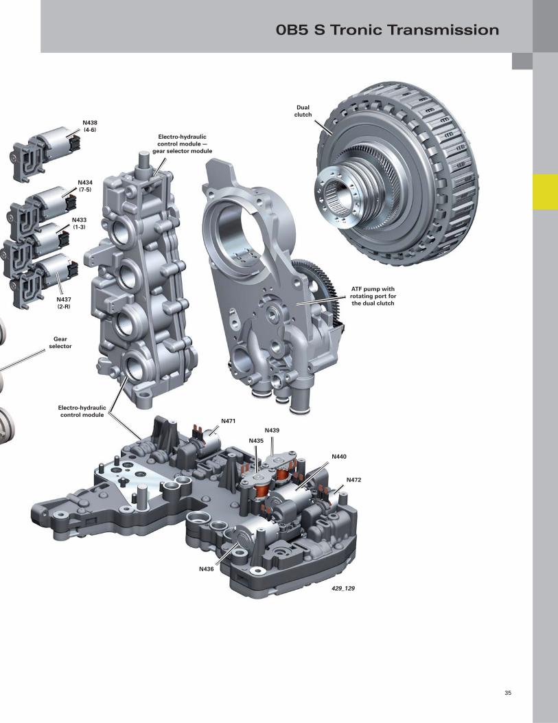
Hydraulic Component Overview
This illustration shows the electro-hydraulic control module,
together with all components activated by the actuators.
N433 Sub Transmission 1 Valve 1 (for gear selector 1-3)
N434 Sub Transmission 1 Valve 2 (for gear selector 7-5)
N435 Sub Transmission 1 Valve 3 (for clutch valve K1, activation)
N436 Sub Transmission 1 Valve 4 (for pressure regulation in sub-gearbox 1)
N437 Sub Transmission 2 Valve 1 (for gear selector 2-R)
N438 Sub Transmission 2 Valve 2 (for gear selector 4-6)
N439 Sub Transmission 2 Valve 3 (for clutch valve K2, activation)
N440 Sub Transmission 2 Valve 4 (for pressure regulation in sub-gearbox 2)
N471 Cooling Oil Valve
N472 Main Pressure Valve
GS = Gear Selector
The selector rails/shift forks have no stops, with the
shift forks held in position by gear selectors. The only
stops are in the gear change sleeve and the synchronizer
assembly.
NoteBefore installing the Mechatronic system
into the transmission, the gear selectors
and selector rails must be brought into
alignment with each other. Refer to the
repair manual.
0B5 S Tronic Transmission
35
N471
ATF pump with rotating port for the dual clutch
Gear selector
Dual clutch
N438 (4-6)
N434 (7-5)
N433 (1-3)
N437 (2-R)
Electro-hydraulic control module
Electro-hydraulic control module —
gear selector module
N435
N436
N439
N440
N472
429_129
0B5 S Tronic Transmission
36
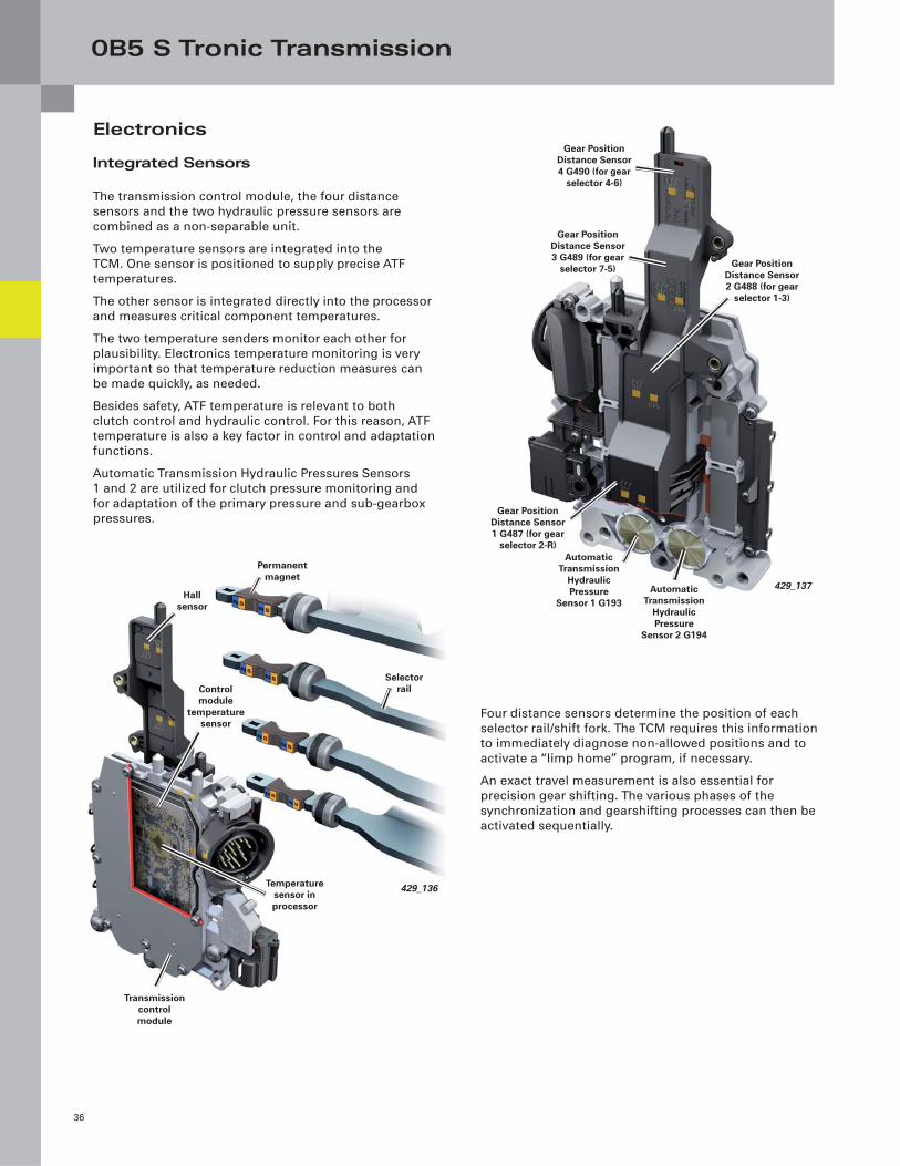
Integrated Sensors
The transmission control module, the four distance
sensors and the two hydraulic pressure sensors are
combined as a non-separable unit.
Two temperature sensors are integrated into the
TCM. One sensor is positioned to supply precise ATF
temperatures.
The other sensor is integrated directly into the processor
and measures critical component temperatures.
The two temperature senders monitor each other for
plausibility. Electronics temperature monitoring is very
important so that temperature reduction measures can
be made quickly, as needed.
Besides safety, ATF temperature is relevant to both
clutch control and hydraulic control. For this reason, ATF
temperature is also a key factor in control and adaptation
functions.
Automatic Transmission Hydraulic Pressures Sensors
1 and 2 are utilized for clutch pressure monitoring and
for adaptation of the primary pressure and sub-gearbox
pressures.
Four distance sensors determine the position of each
selector rail/shift fork. The TCM requires this information
to immediately diagnose non-allowed positions and to
activate a “limp home” program, if necessary.
An exact travel measurement is also essential for
precision gear shifting. The various phases of the
synchronization and gearshifting processes can then be
activated sequentially.
Electronics
Automatic Transmission
Hydraulic Pressure
Sensor 1 G193
429_137
Gear Position Distance Sensor 1 G487 (for gear
selector 2-R)
Automatic Transmission
Hydraulic Pressure
Sensor 2 G194
Gear Position Distance Sensor 4 G490 (for gear
selector 4-6)
Gear Position Distance Sensor 3 G489 (for gear
selector 7-5) Gear Position Distance Sensor 2 G488 (for gear
selector 1-3)
Control module
temperature sensor
Selector rail
Permanent magnet
Hall sensor
Temperature sensor in processor
Transmission control module
429_136
0B5 S Tronic Transmission
37
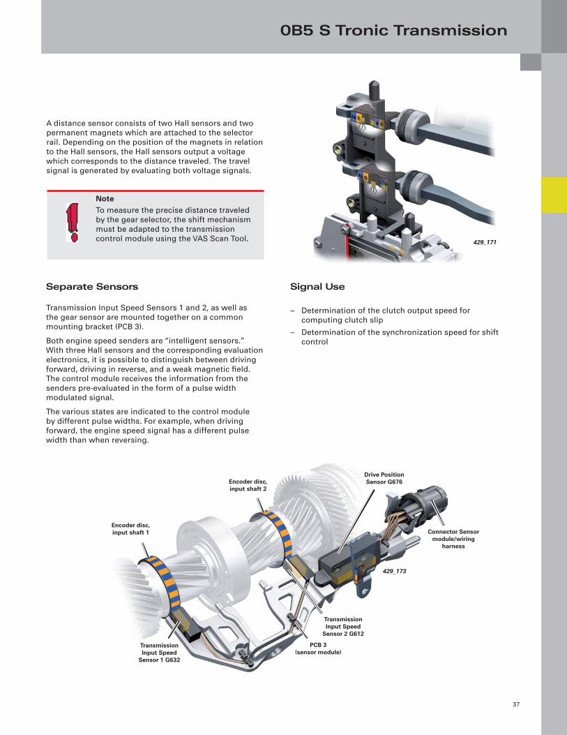
A distance sensor consists of two Hall sensors and two
permanent magnets which are attached to the selector
rail. Depending on the position of the magnets in relation
to the Hall sensors, the Hall sensors output a voltage
which corresponds to the distance traveled. The travel
signal is generated by evaluating both voltage signals.
Signal Use
– Determination of the clutch output speed for
computing clutch slip
– Determination of the synchronization speed for shift
control
NoteTo measure the precise distance traveled
by the gear selector, the shift mechanism
must be adapted to the transmission
control module using the VAS Scan Tool.
Separate Sensors
Transmission Input Speed Sensors 1 and 2, as well as
the gear sensor are mounted together on a common
mounting bracket (PCB 3).
Both engine speed senders are “intelligent sensors.”
With three Hall sensors and the corresponding evaluation
electronics, it is possible to distinguish between driving
forward, driving in reverse, and a weak magnetic fi eld.
The control module receives the information from the
senders pre-evaluated in the form of a pulse width
modulated signal.
The various states are indicated to the control module
by different pulse widths. For example, when driving
forward, the engine speed signal has a different pulse
width than when reversing.
Transmission Input Speed
Sensor 1 G632
Drive Position Sensor G676
Connector Sensor module/wiring
harness
Encoder disc, input shaft 2
429_173
Transmission Input Speed
Sensor 2 G612
PCB 3(sensor module)
Encoder disc, input shaft 1
429_171
0B5 S Tronic Transmission
38
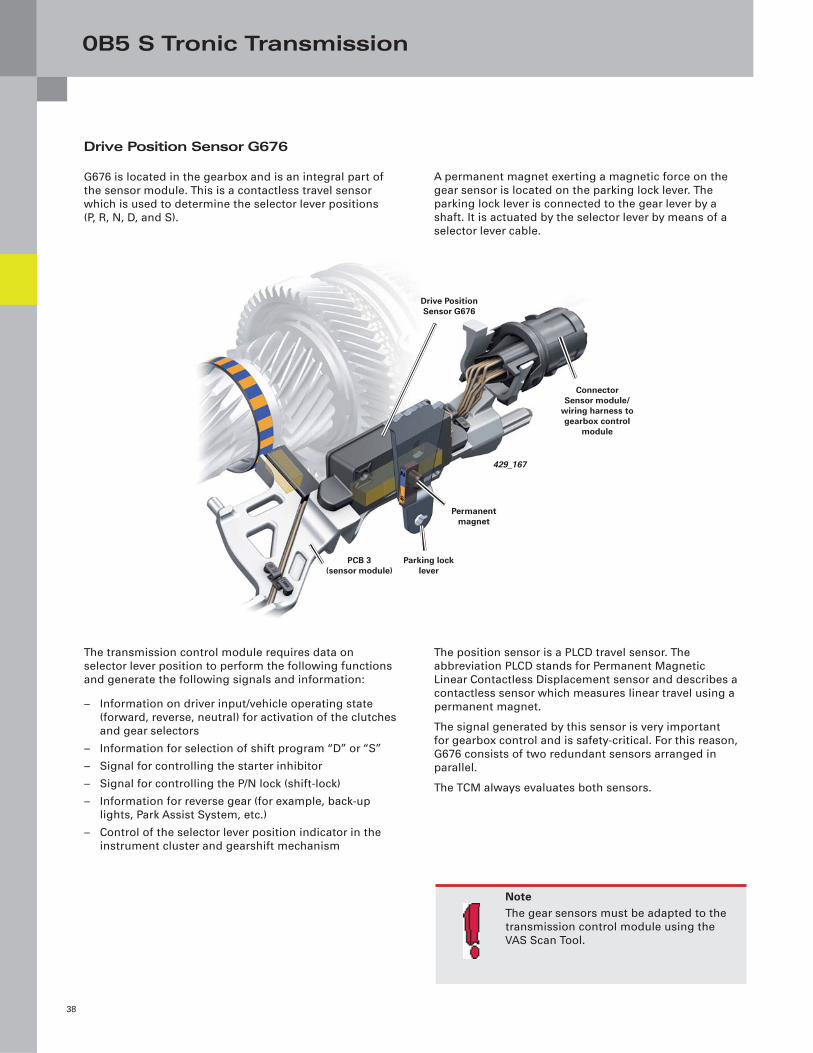
Drive Position Sensor G676
G676 is located in the gearbox and is an integral part of
the sensor module. This is a contactless travel sensor
which is used to determine the selector lever positions
(P, R, N, D, and S).
A permanent magnet exerting a magnetic force on the
gear sensor is located on the parking lock lever. The
parking lock lever is connected to the gear lever by a
shaft. It is actuated by the selector lever by means of a
selector lever cable.
NoteThe gear sensors must be adapted to the
transmission control module using the
VAS Scan Tool.
The transmission control module requires data on
selector lever position to perform the following functions
and generate the following signals and information:
– Information on driver input/vehicle operating state
(forward, reverse, neutral) for activation of the clutches
and gear selectors
– Information for selection of shift program “D” or “S”
– Signal for controlling the starter inhibitor
– Signal for controlling the P/N lock (shift-lock)
– Information for reverse gear (for example, back-up
lights, Park Assist System, etc.)
– Control of the selector lever position indicator in the
instrument cluster and gearshift mechanism
The position sensor is a PLCD travel sensor. The
abbreviation PLCD stands for Permanent Magnetic
Linear Contactless Displacement sensor and describes a
contactless sensor which measures linear travel using a
permanent magnet.
The signal generated by this sensor is very important
for gearbox control and is safety-critical. For this reason,
G676 consists of two redundant sensors arranged in
parallel.
The TCM always evaluates both sensors.
429_167
Parking lock lever
Permanent magnet
PCB 3(sensor module)
Connector Sensor module/
wiring harness to gearbox control
module
Drive Position Sensor G676
0B5 S Tronic Transmission
39
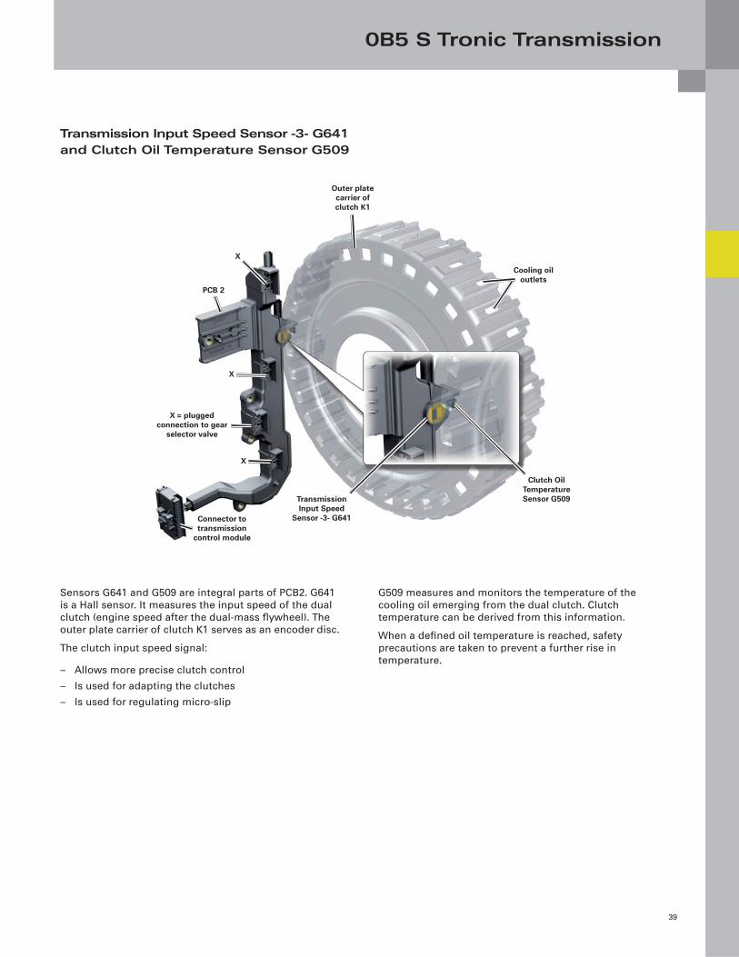
Transmission Input Speed Sensor -3- G641 and Clutch Oil Temperature Sensor G509
Sensors G641 and G509 are integral parts of PCB2. G641
is a Hall sensor. It measures the input speed of the dual
clutch (engine speed after the dual-mass fl ywheel). The
outer plate carrier of clutch K1 serves as an encoder disc.
The clutch input speed signal:
– Allows more precise clutch control
– Is used for adapting the clutches
– Is used for regulating micro-slip
G509 measures and monitors the temperature of the
cooling oil emerging from the dual clutch. Clutch
temperature can be derived from this information.
When a defi ned oil temperature is reached, safety
precautions are taken to prevent a further rise in
temperature.
Connector to transmission
control module
Clutch Oil Temperature Sensor G509Transmission
Input Speed Sensor -3- G641
Cooling oil outlets
Outer plate carrier of clutch K1
X
PCB 2
X
X
X = plugged connection to gear
selector valve
0B5 S Tronic Transmission
40
Control Module Temperature Monitoring
High temperatures have a negative impact on the useful
life and performance of electronic components. Due
to the integration of the transmission control module
into the transmission housing (lubricated by ATF), it is
very important to monitor the temperature of both the
electronics and ATF.
When the temperature reaches approx. 275°F (135°C)
(measured by one of the two temperature sensors in the
transmission control module), the electronics must be
protected against a further rise in temperature. When
this threshold value is exceeded, the transmission control
module initiates a reduction in engine torque to reduce
heat input.
Up to a temperature of approx. 293°F (145 °C), engine
torque can be reduced gradually until the engine is at
idle. When the engine is at idle, the clutches are open
and there is no power transmission from the engine to
the drive wheels.
When the protective function is activated, an entry is
made in the fault memory and the following text message
is displayed in the instrument cluster: “You can continue
driving to a limited extent.”
Clutch Protection
If the clutch cooling oil temperature exceeds a value
of approx. 320°F (160 °C), as determined by G509, the
clutch is within a critical temperature range that can
damage it. These temperatures occur, for example, when
accelerating on extreme gradients, when towing a trailer,
or when the vehicle is held stationary on an uphill slope
using the accelerator and the clutch without engaging
the brake.
As a safety precaution, engine torque is reduced when
cooling oil temperature exceeds 320°F (160 °C.) If the
cooling oil temperature continues to rise, engine torque
is gradually reduced, sometimes to idle. When the engine
is at idle, the clutches are open and there is no power
transmission from the engine to the drive wheels.
When the protective function is initiated, an entry is
made in the fault memory and the following text message
is displayed in the instrument cluster: “You can continue
driving to a limited extent.”
As an additional safety precaution, the clutch
temperature is determined using a computer model. If
the computed temperature exceeds a pre-defi ned value,
the above mentioned precautions are taken.
Transmission Protection Functions
0B5 S Tronic Transmission
41
… transmission control module
In the B8 series, a new data and diagnostic log is used
for the engine control modules, the TCM, and the
airbag control module. The previous data blocks and
numberings are no longer used. Individual measured
data is now available and listed as full text in alphabetical
order. This required measured data can then be
specifi cally selected.
… clearing the fault memory
The fault memories of the engine and transmission
control module are always cleared jointly. If the fault
memory of the transmission control module is cleared,
then the fault memory in the engine control module will
be cleared as well. The converse applies if the memory of
the engine control module is cleared.
… towing
If a vehicle with S tronic needs towing, the conventional
restrictions of automatic transmissions apply:
– Selector lever in position “N”
– A maximum towing speed of 30 mph (50 km/h) must
not be exceeded
– A maximum towing distance of 30 mi (50 km) must not
be exceeded
Explanation:
When the engine is at standstill, the oil pump is not
driven and certain parts of the transmission are no
longer lubricated. Exceeding a speed of 30 mph (50 km/h)
results in unacceptably high rotational speeds within
the gearbox and dual clutch, because one gear is always
engaged in both sub-gearboxes.
If these towing cautions are not observed, serious
transmission damage can occur.
All you need to know about the …
0B5 S Tronic Transmission
42
In the event of a malfunction, serious damage can be
prevented and mobility preserved by means of “limp
home” programs initiated by the transmission control
module. In addition, there are also protective functions,
which protect certain components against overload.
In the event of certain pre-defi ned system malfunctions,
the transmission control module shuts down the sub-
gearbox in question and activates the relevant “limp
home” program (driving with intact sub-gearbox).
1. Driving with sub-gearbox 1, sub-gearbox 2 shut down:
– Only gears 1, 3, 5, and 7* can be engaged (with
interruption in tractive power)
– Backing up (reversing) is not possible
2. Driving with sub-gearbox 2, sub-gearbox 1 shut down:
Only gears 2, 4, 6, and R* can be engaged (with
interruption in tractive power).
3. Complete gearbox shutdown:
In the case of serious faults — for example, a faulty
powertrain CAN, no identifi cation by the immobilizer, or
recognition of an incorrect ratio in the gear steps or in
the fi nal drive — the gearbox is completely shut down.
“Limp Home” Programs
* The nature of the fault dictates which gears are
still available. To be sure that components do not
overspeed, certain gears are disabled depending on
fault type. After ensuring that no gear is engaged in
the deactivated gearbox, all gears of the intact sub-
gearbox are shifted without any further restrictions.
0B5 S Tronic Transmission
43
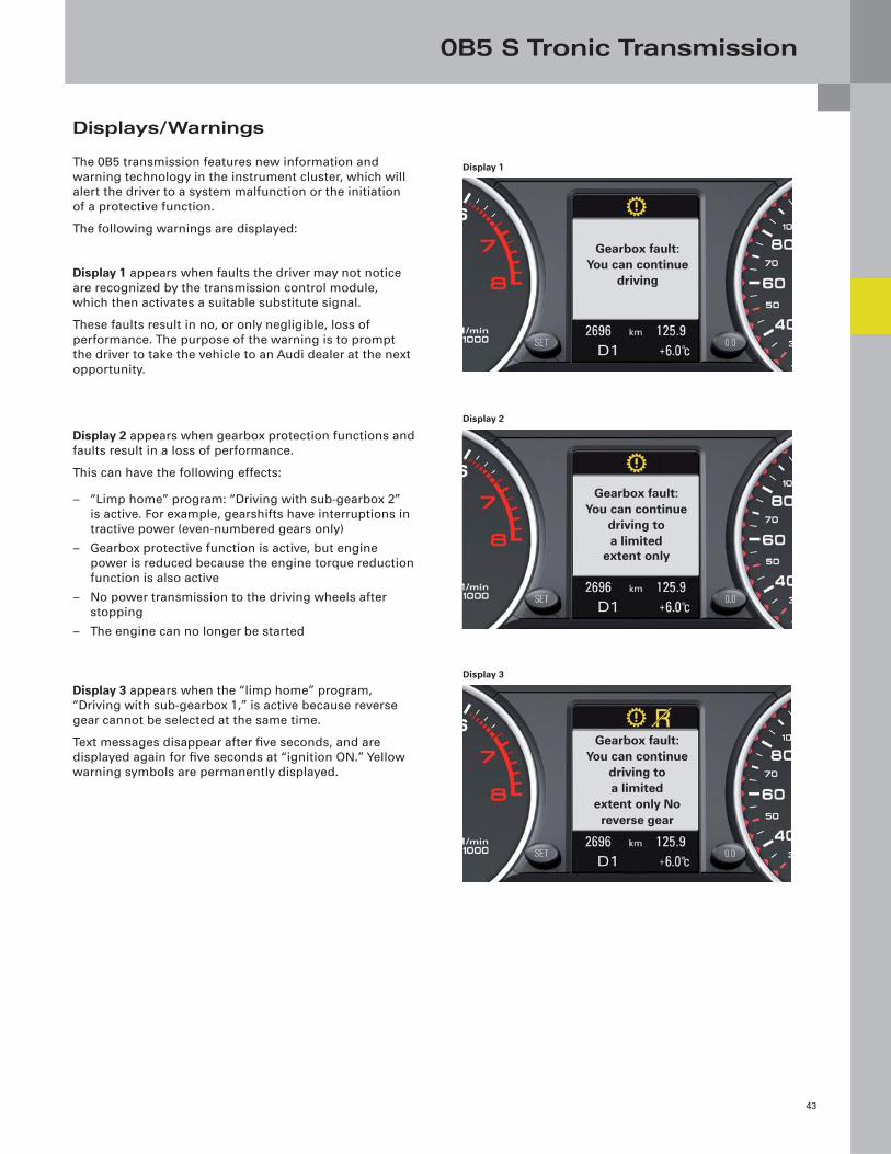
Displays/Warnings
The 0B5 transmission features new information and
warning technology in the instrument cluster, which will
alert the driver to a system malfunction or the initiation
of a protective function.
The following warnings are displayed:
Display 1 appears when faults the driver may not notice
are recognized by the transmission control module,
which then activates a suitable substitute signal.
These faults result in no, or only negligible, loss of
performance. The purpose of the warning is to prompt
the driver to take the vehicle to an Audi dealer at the next
opportunity.
Display 2 appears when gearbox protection functions and
faults result in a loss of performance.
This can have the following effects:
– “Limp home” program: “Driving with sub-gearbox 2”
is active. For example, gearshifts have interruptions in
tractive power (even-numbered gears only)
– Gearbox protective function is active, but engine
power is reduced because the engine torque reduction
function is also active
– No power transmission to the driving wheels after
stopping
– The engine can no longer be started
Display 3 appears when the “limp home” program,
“Driving with sub-gearbox 1,” is active because reverse
gear cannot be selected at the same time.
Text messages disappear after fi ve seconds, and are
displayed again for fi ve seconds at “ignition ON.” Yellow
warning symbols are permanently displayed.
Gearbox fault:You can continue
driving
Display 1
Gearbox fault:You can continue
driving toa limited
extent only
Display 2
Gearbox fault:You can continue
driving toa limited
extent only Noreverse gear
Display 3
Sport Differential
44
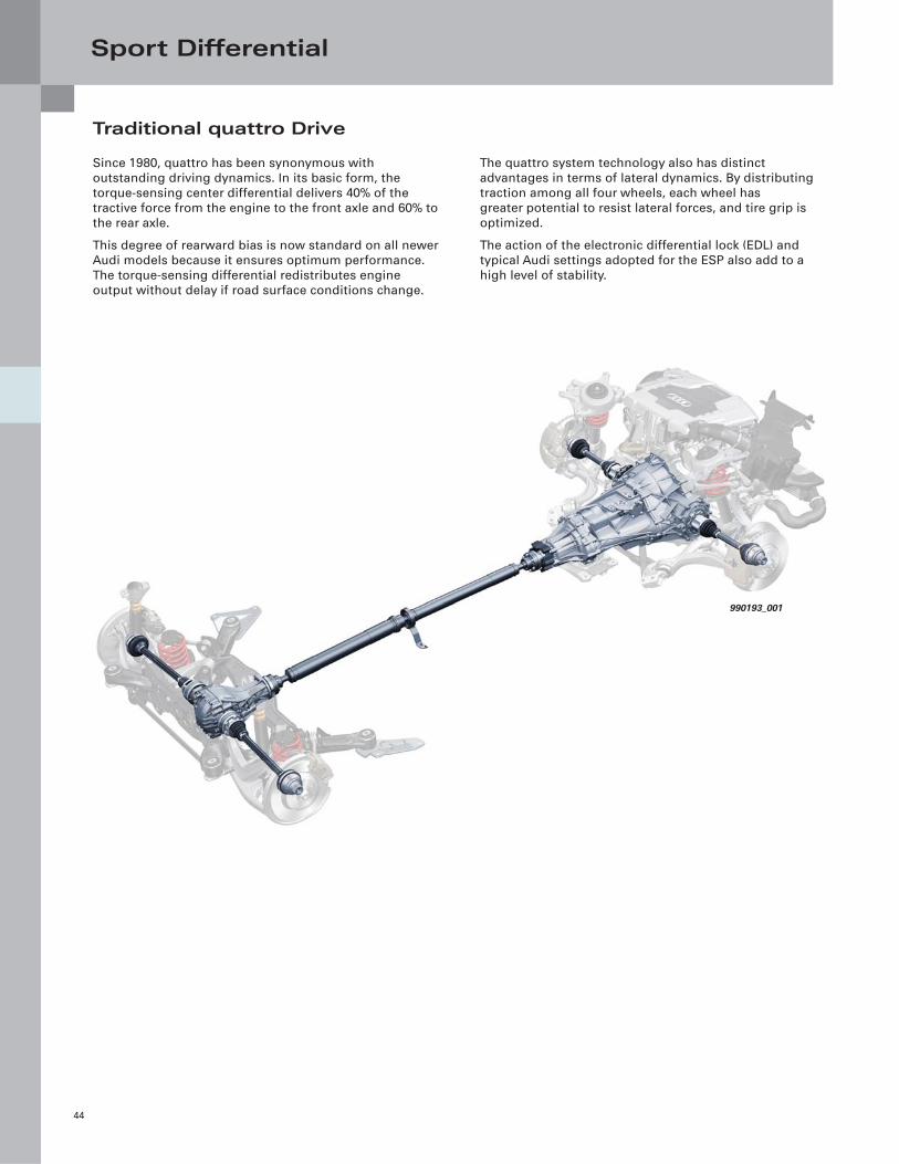
Traditional quattro Drive
Since 1980, quattro has been synonymous with
outstanding driving dynamics. In its basic form, the
torque-sensing center differential delivers 40% of the
tractive force from the engine to the front axle and 60% to
the rear axle.
This degree of rearward bias is now standard on all newer
Audi models because it ensures optimum performance.
The torque-sensing differential redistributes engine
output without delay if road surface conditions change.
The quattro system technology also has distinct
advantages in terms of lateral dynamics. By distributing
traction among all four wheels, each wheel has
greater potential to resist lateral forces, and tire grip is
optimized.
The action of the electronic differential lock (EDL) and
typical Audi settings adopted for the ESP also add to a
high level of stability.
990193_001
Sport Differential
45
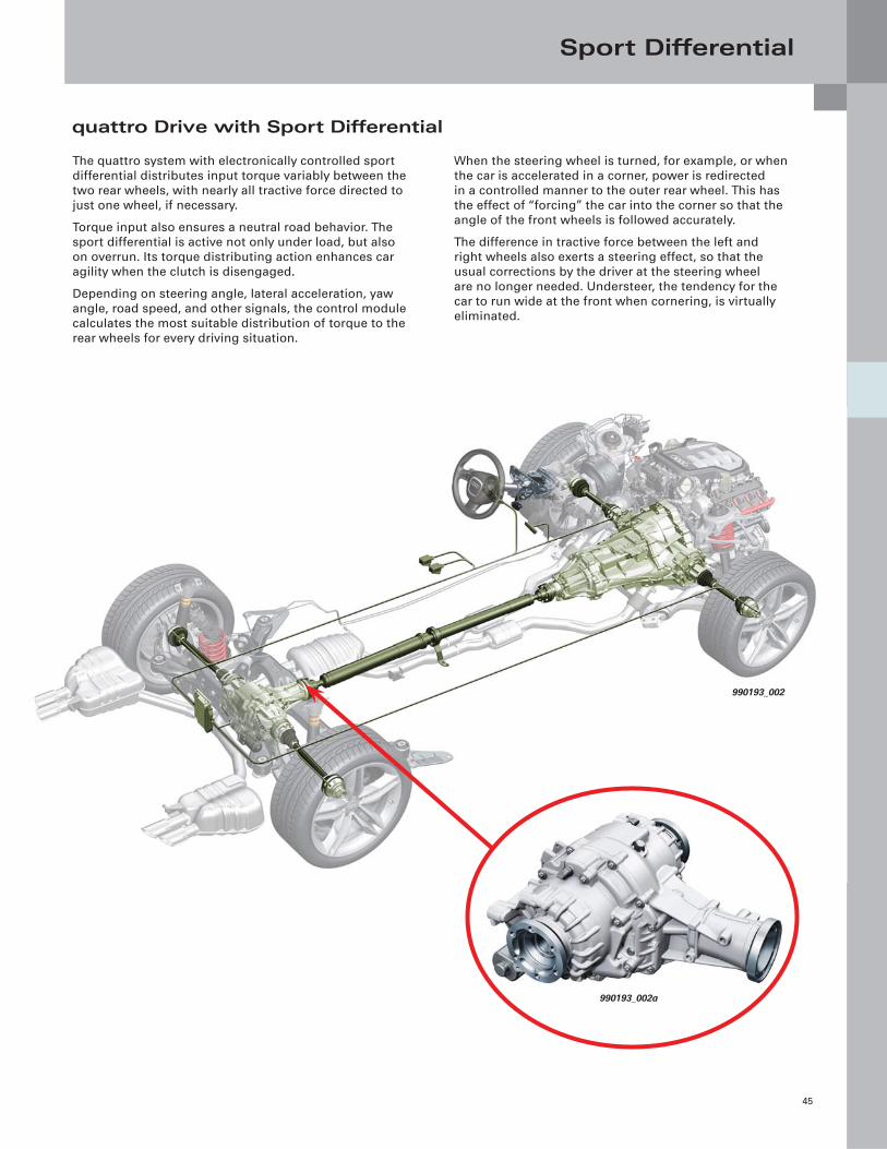
The quattro system with electronically controlled sport
differential distributes input torque variably between the
two rear wheels, with nearly all tractive force directed to
just one wheel, if necessary.
Torque input also ensures a neutral road behavior. The
sport differential is active not only under load, but also
on overrun. Its torque distributing action enhances car
agility when the clutch is disengaged.
Depending on steering angle, lateral acceleration, yaw
angle, road speed, and other signals, the control module
calculates the most suitable distribution of torque to the
rear wheels for every driving situation.
When the steering wheel is turned, for example, or when
the car is accelerated in a corner, power is redirected
in a controlled manner to the outer rear wheel. This has
the effect of “forcing” the car into the corner so that the
angle of the front wheels is followed accurately.
The difference in tractive force between the left and
right wheels also exerts a steering effect, so that the
usual corrections by the driver at the steering wheel
are no longer needed. Understeer, the tendency for the
car to run wide at the front when cornering, is virtually
eliminated.
quattro Drive with Sport Differential
990193_002
990193_002a
Sport Differential
46
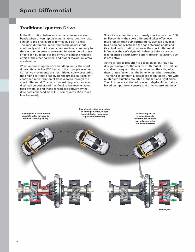
Traditional quattro Drive
In the illustration below, a car adheres to successive
bends when driven rapidly along a typical country road,
similar to the precise track formed by skis in snow.
The sport differential redistributes the power input
continually and quickly and counteracts any tendency for
the car to understeer or oversteer before either of these
effects can build up. For the driver, this means reduced
effort at the steering wheel and higher maximum lateral
acceleration.
When approaching the car’s handling limits, the sport
differential acts like ESP, but with the principle reversed.
Corrective movements are not initiated solely by altering
the engine settings or applying the brakes, but also by
controlled redistribution of tractive force through the
sport differential. The car’s forward progress becomes
distinctly smoother and free-fl owing because its actual
road dynamics and those sensed subjectively by the
driver are enhanced since ESP comes into action much
less frequently.
Since its reaction time is extremely short — less than 100
milliseconds — the sport differential takes effect even
more rapidly than ESP. Furthermore, ESP can only react
to a discrepancy between the car’s steering angle and
its actual body rotation, whereas the sport differential
infl uences the car’s dynamic behavior before any such
discrepancies occur. During sport differential action, ESP
is not active.
Active torque distribution is based on an entirely new
design principle for the rear axle differential. The unit can
also divert torque to the outer wheel on the axle, which
then rotates faster than the inner wheel when cornering.
The rear axle differential has speed modulation units with
multi-plate clutches mounted at the left and right sides.
The clutches are activated by electro-hydraulic actuators
based on input from sensors and other control modules.
Steering into a curve: torque is redistributed outward to enhance cornering ability
Changing direction: depending on driving situation, torque is redistributed to enhance
agility and/or stabilityAccelerating out of a curve: torque is
redistributed outward to avoid acceleration-induced understeer
990193_003
Sport Differential
47
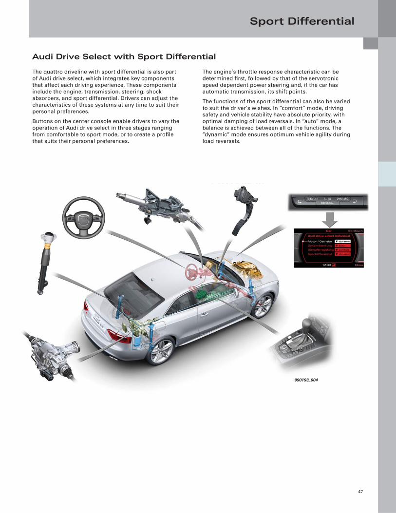
The quattro driveline with sport differential is also part
of Audi drive select, which integrates key components
that affect each driving experience. These components
include the engine, transmission, steering, shock
absorbers, and sport differential. Drivers can adjust the
characteristics of these systems at any time to suit their
personal preferences.
Buttons on the center console enable drivers to vary the
operation of Audi drive select in three stages ranging
from comfortable to sport mode, or to create a profi le
that suits their personal preferences.
The engine’s throttle response characteristic can be
determined fi rst, followed by that of the servotronic
speed dependent power steering and, if the car has
automatic transmission, its shift points.
The functions of the sport differential can also be varied
to suit the driver’s wishes. In “comfort” mode, driving
safety and vehicle stability have absolute priority, with
optimal damping of load reversals. In “auto” mode, a
balance is achieved between all of the functions. The
“dynamic” mode ensures optimum vehicle agility during
load reversals.
Audi Drive Select with Sport Differential
990193_004
Sport Differential
48
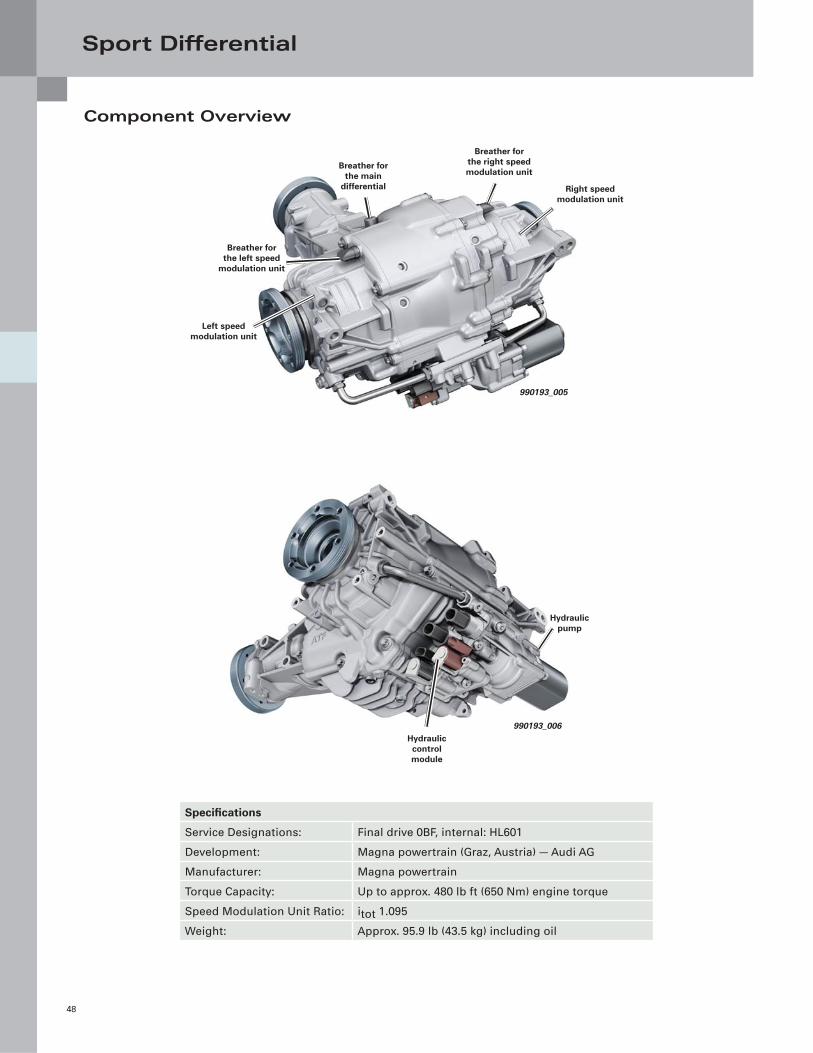
Component Overview
Specifi cations
Service Designations: Final drive 0BF, internal: HL601
Development: Magna powertrain (Graz, Austria) — Audi AG
Manufacturer: Magna powertrain
Torque Capacity: Up to approx. 480 lb ft (650 Nm) engine torque
Speed Modulation Unit Ratio: itot 1.095
Weight: Approx. 95.9 lb (43.5 kg) including oil
990193_005
Breather for the left speed
modulation unit
Left speed modulation unit
Breather for the right speed modulation unit
Right speed modulation unit
Breather for the main
differential
990193_006
Hydraulic control module
Hydraulic pump
Sport Differential
49
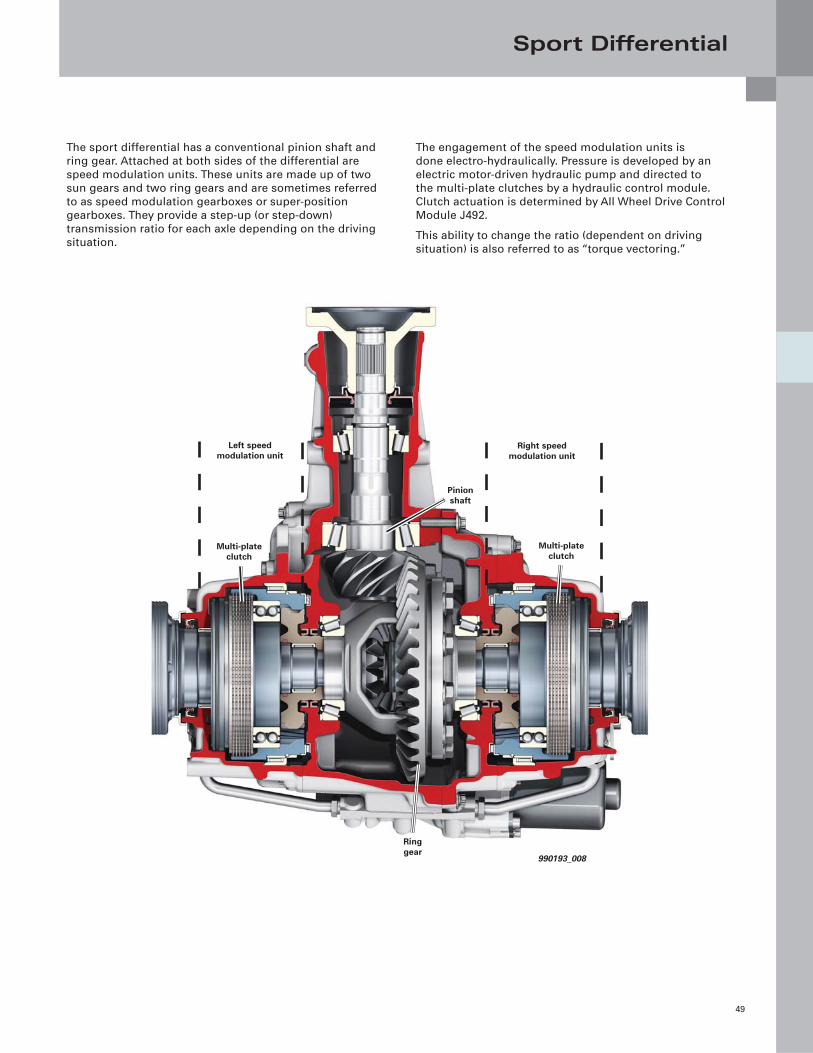
The sport differential has a conventional pinion shaft and
ring gear. Attached at both sides of the differential are
speed modulation units. These units are made up of two
sun gears and two ring gears and are sometimes referred
to as speed modulation gearboxes or super-position
gearboxes. They provide a step-up (or step-down)
transmission ratio for each axle depending on the driving
situation.
The engagement of the speed modulation units is
done electro-hydraulically. Pressure is developed by an
electric motor-driven hydraulic pump and directed to
the multi-plate clutches by a hydraulic control module.
Clutch actuation is determined by All Wheel Drive Control
Module J492.
This ability to change the ratio (dependent on driving
situation) is also referred to as “torque vectoring.”
990193_008
Pinion shaft
Multi-plate clutch
Multi-plate clutch
Ring gear
Right speed modulation unit
Left speed modulation unit
Sport Differential
50
990193_009
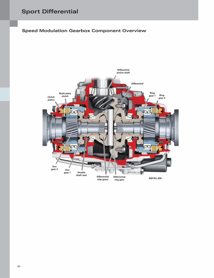
Multi-plate clutch
Differential pinion shaft
Ring gear 1
Differential
Ring gear 2
Sun gear 2
Differential ring gear
Sun gear 1
Differential side gears
Double shaft seal
Clutch piston
Speed Modulation Gearbox Component Overview
Sport Differential
51
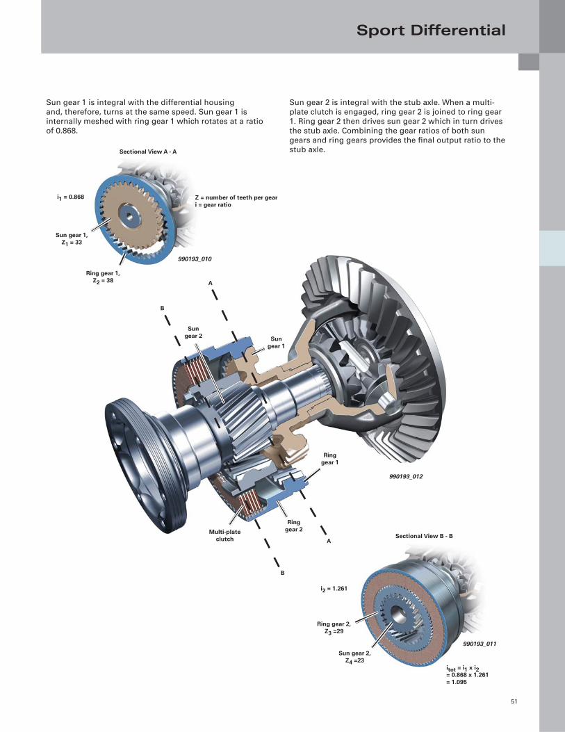
Sun gear 1 is integral with the differential housing
and, therefore, turns at the same speed. Sun gear 1 is
internally meshed with ring gear 1 which rotates at a ratio
of 0.868.
Sun gear 2 is integral with the stub axle. When a multi-
plate clutch is engaged, ring gear 2 is joined to ring gear
1. Ring gear 2 then drives sun gear 2 which in turn drives
the stub axle. Combining the gear ratios of both sun
gears and ring gears provides the fi nal output ratio to the
stub axle.
990193_012
Sun gear 1
Sun gear 2
Ring gear 1
Multi-plate clutch
Ring gear 2
A
B
A
B
990193_011
Ring gear 2, Z3 =29
Sun gear 2, Z4 =23
i2 = 1.261
Sectional View B - B
itot = i1 x i2= 0.868 x 1.261= 1.095
990193_010
Z = number of teeth per geari = gear ratio
Ring gear 1, Z2 = 38
Sun gear 1, Z1 = 33
i1 = 0.868
Sectional View A - A
Sport Differential
52
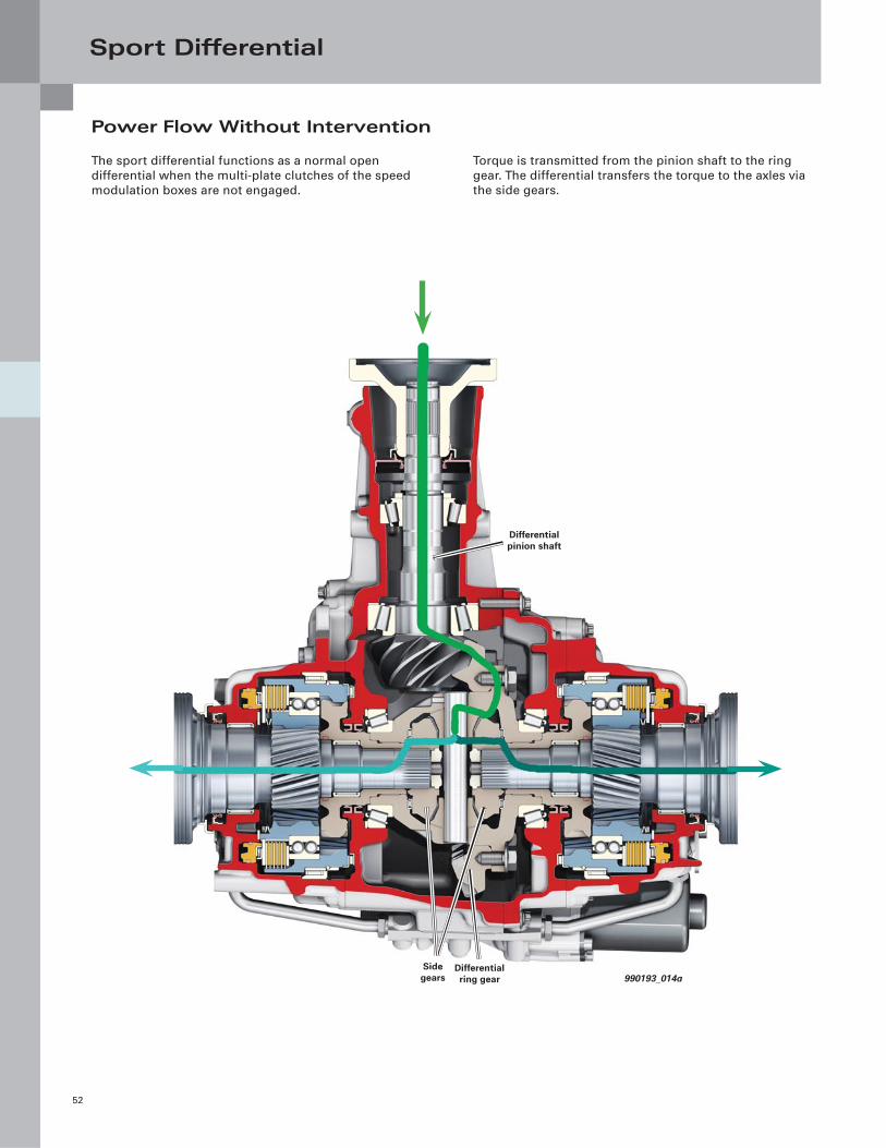
Power Flow Without Intervention
The sport differential functions as a normal open
differential when the multi-plate clutches of the speed
modulation boxes are not engaged.
Torque is transmitted from the pinion shaft to the ring
gear. The differential transfers the torque to the axles via
the side gears.
990193_014a
Side gears
Differential pinion shaft
Differential ring gear
Sport Differential
53
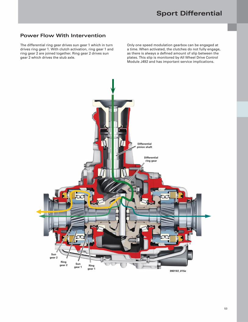
Power Flow With Intervention
The differential ring gear drives sun gear 1 which in turn
drives ring gear 1. With clutch activation, ring gear 1 and
ring gear 2 are joined together. Ring gear 2 drives sun
gear 2 which drives the stub axle.
Only one speed modulation gearbox can be engaged at
a time. When activated, the clutches do not fully engage,
as there is always a defi ned amount of slip between the
plates. This slip is monitored by All Wheel Drive Control
Module J492 and has important service implications.
Differential pinion shaft
Sun gear 1
Differential ring gear
Sun gear 2
Ring gear 2 Ring
gear 1990193_015a
Sport Differential
54
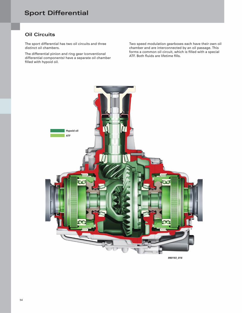
Oil Circuits
The sport differential has two oil circuits and three
distinct oil chambers.
The differential pinion and ring gear (conventional
differential components) have a separate oil chamber
fi lled with hypoid oil.
Two speed modulation gearboxes each have their own oil
chamber and are interconnected by an oil passage. This
forms a common oil circuit, which is fi lled with a special
ATF. Both fl uids are lifetime fi lls.
990193_016
Hypoid oil
ATF
Sport Differential
55
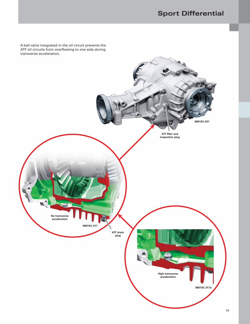
A ball valve integrated in the oil circuit prevents the
ATF oil circuits from overfl owing to one side during
transverse acceleration.
990193_031
990193_017
990193_017a
ATF fi ller and inspection plug
ATF drain plug
No transverse acceleration
High transverse acceleration
Sport Differential
56
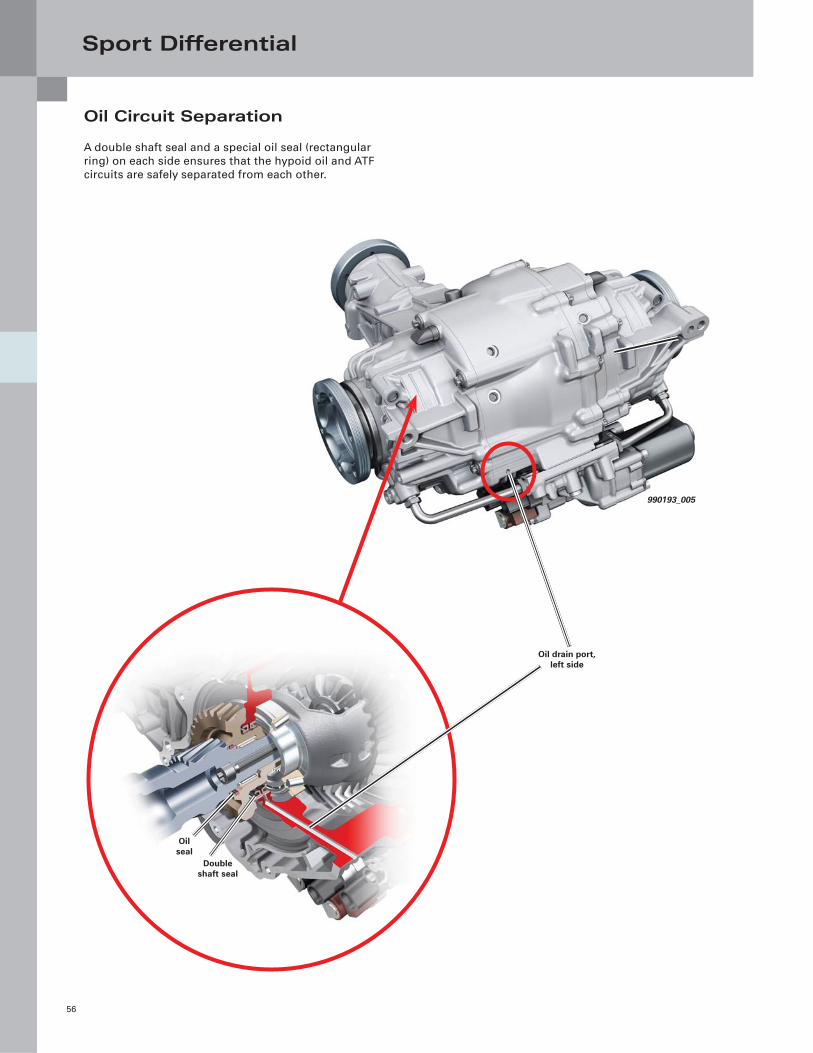
Oil Circuit Separation
A double shaft seal and a special oil seal (rectangular
ring) on each side ensures that the hypoid oil and ATF
circuits are safely separated from each other.
990193_018
990193_005
Double shaft seal
Oil seal
Oil drain port, left side
Sport Differential
57
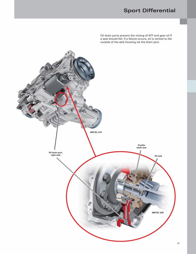
Oil drain ports prevent the mixing of ATF and gear oil if
a seal should fail. If a failure occurs, oil is vented to the
outside of the axle housing via the drain port.
990193_019
990193_020
Oil drain port, right side Oil seal
Double shaft seal
Sport Differential
58
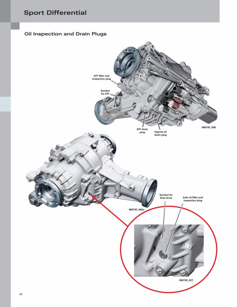
Oil Inspection and Drain Plugs
990193_002a
990193_021
Axle oil fi ller and inspection plug
Symbol for fi nal drive
990193_006
ATF fi ller and inspection plug
Symbol for ATF
ATF drain plug Hypoid oil
drain plug
Sport Differential
59
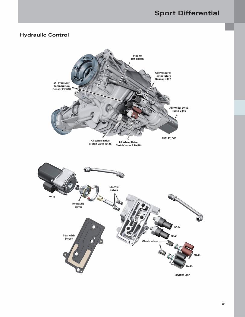
Hydraulic Control
990193_006All Wheel Drive
Clutch Valve N445
Oil Pressure/Temperature Sensor G437
Pipe to left clutch
Oil Pressure/ Temperature
Sensor 2 G640
All Wheel-Drive Pump V415
All Wheel Drive Clutch Valve 2 N446
990193_022
Seal with Screen
N445
Hydraulic pump
V415
Check valves
Shuttle valves
N446
G437
G640
Sport Differential
60
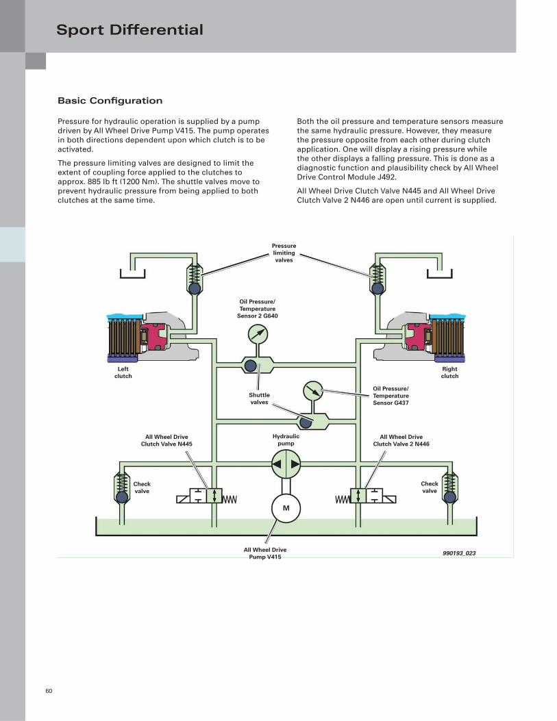
Basic Confi guration
Pressure for hydraulic operation is supplied by a pump
driven by All Wheel Drive Pump V415. The pump operates
in both directions dependent upon which clutch is to be
activated.
The pressure limiting valves are designed to limit the
extent of coupling force applied to the clutches to
approx. 885 lb ft (1200 Nm). The shuttle valves move to
prevent hydraulic pressure from being applied to both
clutches at the same time.
Both the oil pressure and temperature sensors measure
the same hydraulic pressure. However, they measure
the pressure opposite from each other during clutch
application. One will display a rising pressure while
the other displays a falling pressure. This is done as a
diagnostic function and plausibility check by All Wheel
Drive Control Module J492.
All Wheel Drive Clutch Valve N445 and All Wheel Drive
Clutch Valve 2 N446 are open until current is supplied.
990193_023
Left clutch
Oil Pressure/Temperature Sensor G437
M
Pressure limiting valves
Right clutch
Hydraulic pump
Check valve
Shuttle valves
Oil Pressure/Temperature
Sensor 2 G640
All Wheel Drive Clutch Valve N445
All Wheel Drive Clutch Valve 2 N446
All Wheel Drive Pump V415
Check valve
Sport Differential
61
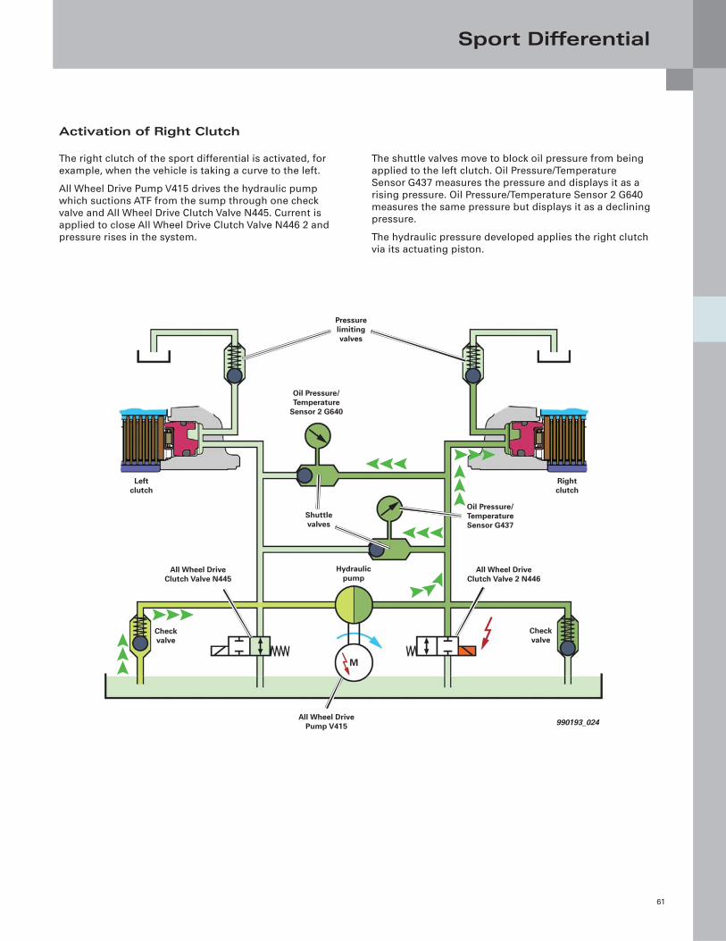
Activation of Right Clutch
The right clutch of the sport differential is activated, for
example, when the vehicle is taking a curve to the left.
All Wheel Drive Pump V415 drives the hydraulic pump
which suctions ATF from the sump through one check
valve and All Wheel Drive Clutch Valve N445. Current is
applied to close All Wheel Drive Clutch Valve N446 2 and
pressure rises in the system.
The shuttle valves move to block oil pressure from being
applied to the left clutch. Oil Pressure/Temperature
Sensor G437 measures the pressure and displays it as a
rising pressure. Oil Pressure/Temperature Sensor 2 G640
measures the same pressure but displays it as a declining
pressure.
The hydraulic pressure developed applies the right clutch
via its actuating piston.
990193_024
Left clutch
Oil Pressure/Temperature Sensor G437
M
Pressure limiting valves
Right clutch
Hydraulic pump
Check valve
Shuttle valves
Oil Pressure/Temperature
Sensor 2 G640
All Wheel Drive Clutch Valve N445
All Wheel Drive Clutch Valve 2 N446
All Wheel Drive Pump V415
Check valve
Sport Differential
62
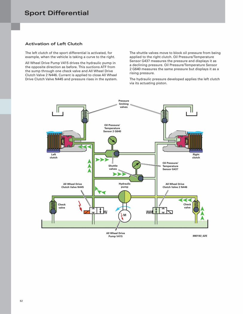
Activation of Left Clutch
The left clutch of the sport differential is activated, for
example, when the vehicle is taking a curve to the right.
All Wheel Drive Pump V415 drives the hydraulic pump in
the opposite direction as before. This suctions ATF from
the sump through one check valve and All Wheel Drive
Clutch Valve 2 N446. Current is applied to close All Wheel
Drive Clutch Valve N445 and pressure rises in the system.
The shuttle valves move to block oil pressure from being
applied to the right clutch. Oil Pressure/Temperature
Sensor G437 measures the pressure and displays it as
a declining pressure. Oil Pressure/Temperature Sensor
2 G640 measures the same pressure but displays it as a
rising pressure.
The hydraulic pressure developed applies the left clutch
via its actuating piston.
990193_025
Left clutch
Oil Pressure/Temperature Sensor G437
M
Pressure limiting valves
Right clutch
Hydraulic pump
Check valve
Shuttle valves
Oil Pressure/Temperature
Sensor 2 G640
All Wheel Drive Clutch Valve N445
All Wheel Drive Clutch Valve 2 N446
All Wheel Drive Pump V415
Check valve
Sport Differential
63
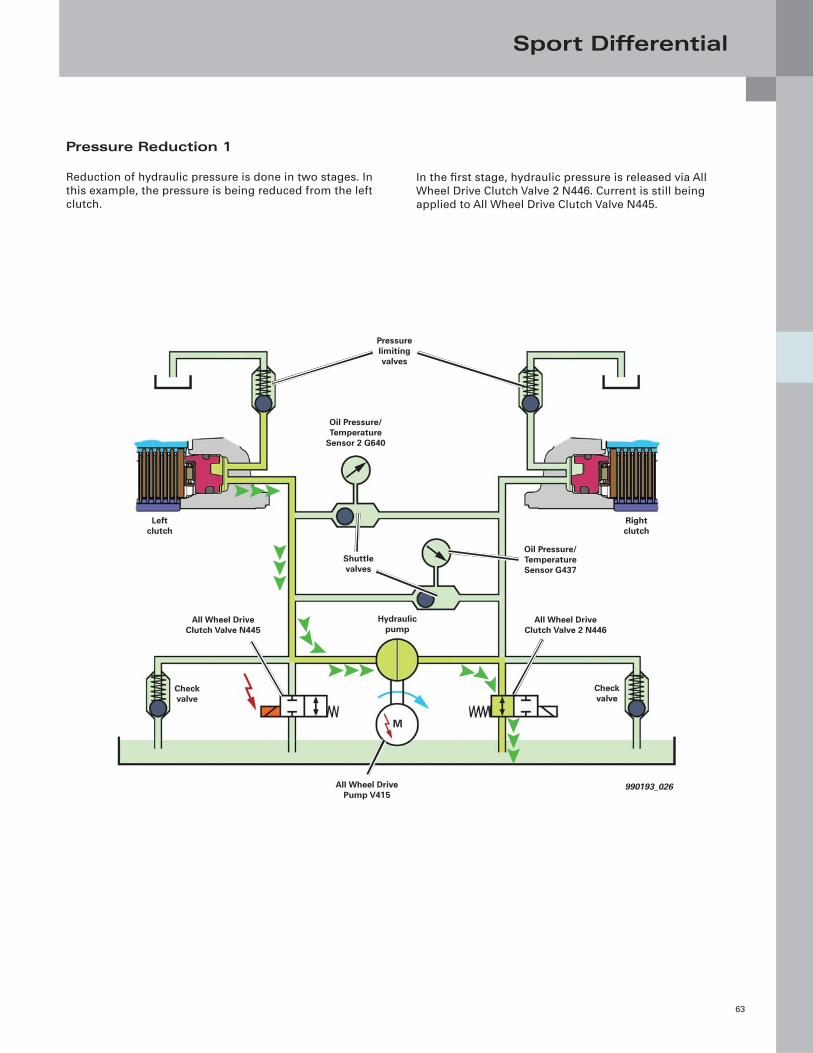
Pressure Reduction 1
Reduction of hydraulic pressure is done in two stages. In
this example, the pressure is being reduced from the left
clutch.
In the fi rst stage, hydraulic pressure is released via All
Wheel Drive Clutch Valve 2 N446. Current is still being
applied to All Wheel Drive Clutch Valve N445.
990193_026
Left clutch
Oil Pressure/Temperature Sensor G437
M
Pressure limiting valves
Right clutch
Hydraulic pump
Check valve
Shuttle valves
Oil Pressure/Temperature
Sensor 2 G640
All Wheel Drive Clutch Valve N445
All Wheel Drive Clutch Valve 2 N446
All Wheel Drive Pump V415
Check valve
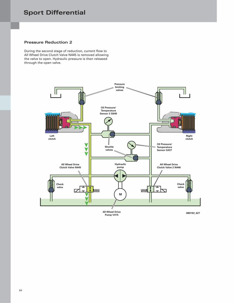
Sport Differential
64
Pressure Reduction 2
During the second stage of reduction, current fl ow to
All Wheel Drive Clutch Valve N445 is removed allowing
the valve to open. Hydraulic pressure is then released
through the open valve.
990193_027
Left clutch
Oil Pressure/Temperature Sensor G437
M
Pressure limiting valves
Right clutch
Hydraulic pump
Check valve
Shuttle valves
Oil Pressure/Temperature
Sensor 2 G640
All Wheel Drive Clutch Valve N445
All Wheel Drive Clutch Valve 2 N446
All Wheel Drive Pump V415
Check valve
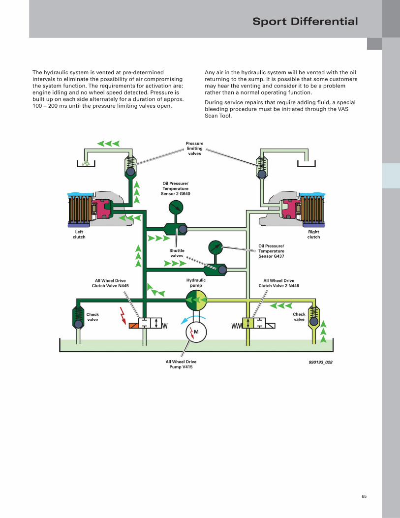
Sport Differential
65
The hydraulic system is vented at pre-determined
intervals to eliminate the possibility of air compromising
the system function. The requirements for activation are:
engine idling and no wheel speed detected. Pressure is
built up on each side alternately for a duration of approx.
100 – 200 ms until the pressure limiting valves open.
Any air in the hydraulic system will be vented with the oil
returning to the sump. It is possible that some customers
may hear the venting and consider it to be a problem
rather than a normal operating function.
During service repairs that require adding fl uid, a special
bleeding procedure must be initiated through the VAS
Scan Tool.
990193_028
Left clutch
Oil Pressure/Temperature Sensor G437
M
Pressure limiting valves
Right clutch
Hydraulic pump
Check valve
Shuttle valves
Oil Pressure/Temperature
Sensor 2 G640
All Wheel Drive Clutch Valve N445
All Wheel Drive Clutch Valve 2 N446
All Wheel Drive Pump V415
Check valve
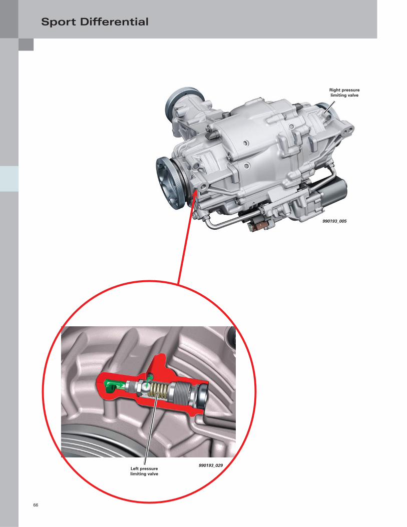
Sport Differential
66
990193_005
990193_029
Right pressure limiting valve
Left pressure limiting valve
Sport Differential
67
Important Service Notes
Both the ATF fi ll and hypoid gear oil fi ll are lifetime oils
and do not require changing during routine scheduled
maintenance. However, if repairs to the hydraulic controls
are made, for example changing of the Oil Pressure/
Temperature Sensors, All Wheel Drive Clutch Valves or
hydraulic pump, the oil levels must be topped off. After
this is done, a special bleeding process must be carried
out via the scan tool.
Oil Pressure/Temperature Sensors G437 and G640 have
their own serial numbers and characteristics. They are
used to establish the identity of the sport differential for
All Wheel Drive Control Module J492. They are color-
coded and must not be installed in the wrong positions.
G437 and G640 should never (if possible) be replaced
at the same time. Always replace one after the other. If
this isn’t done, All Wheel Drive Control Module J492 will
assume a new sport differential has been installed and
additional adaptation and maintenance procedures will
be necessary, including changing of the ATF.
The speed modulation gearboxes (or super-position
gearboxes) are tested and calibrated during the
manufacturing process. The tolerances for each gearbox
are inscribed on the sport differential housing in the form
of a hexadecimal code. This code is used for adaptation
via the VAS Scan Tool when repairs are made to the
differential.
The VAS Scan Tool is used to diagnose the sport
differential system. Information is found under Address
Word 22.
In addition to doing adaptations and coding procedures,
it is also possible to perform output check diagnosis.
The output checks allow you to bleed the system, check
the over-all functionality of the system, and to check
the applied torque of the left and right clutches. This
information is found in both Guided Functions and
Guided Fault Finding.
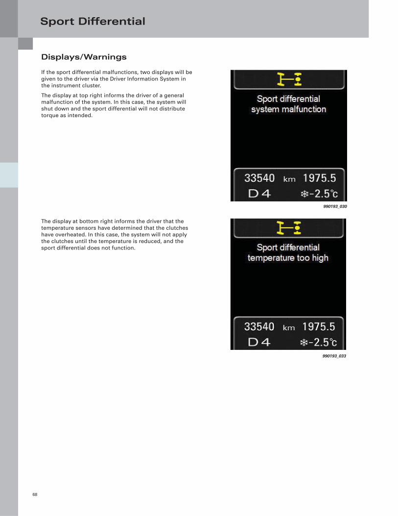
Sport Differential
68
Displays/Warnings
If the sport differential malfunctions, two displays will be
given to the driver via the Driver Information System in
the instrument cluster.
The display at top right informs the driver of a general
malfunction of the system. In this case, the system will
shut down and the sport differential will not distribute
torque as intended.
990193_030
990193_033
The display at bottom right informs the driver that the
temperature sensors have determined that the clutches
have overheated. In this case, the system will not apply
the clutches until the temperature is reduced, and the
sport differential does not function.
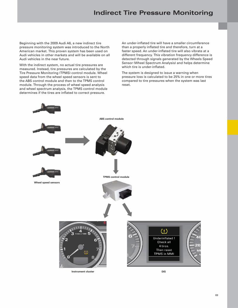
Indirect Tire Pressure Monitoring
69
An under-infl ated tire will have a smaller circumference
than a properly infl ated tire and therefore, turn at a
faster speed. An under-infl ated tire will also vibrate at a
different frequency. This vibration frequency difference is
detected through signals generated by the Wheels Speed
Sensor (Wheel Spectrum Analysis) and helps determine
which tire is under-infl ated.
The system is designed to issue a warning when
pressure loss is calculated to be 25% in one or more tires
compared to tire pressures when the system was last
reset.
Beginning with the 2009 Audi A6, a new indirect tire
pressure monitoring system was introduced to the North
American market. This proven system has been used on
Audi vehicles in other markets and will be available on all
Audi vehicles in the near future.
With the indirect system, no actual tire pressures are
measured. Instead, tire pressures are calculated by the
Tire Pressure Monitoring (TPMS) control module. Wheel
speed data from the wheel speed sensors is sent to
the ABS control module and then to the TPMS control
module. Through the process of wheel speed analysis
and wheel spectrum analysis, the TPMS control module
determines if the tires are infl ated to correct pressure.
ABS control module
Wheel speed sensors
TPMS control module
Instrument cluster DIS
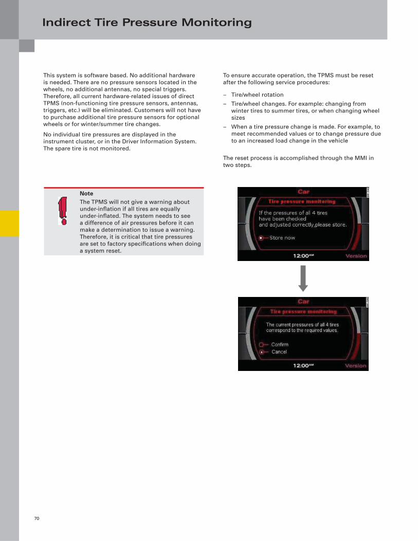
Indirect Tire Pressure Monitoring
70
This system is software based. No additional hardware
is needed. There are no pressure sensors located in the
wheels, no additional antennas, no special triggers.
Therefore, all current hardware-related issues of direct
TPMS (non-functioning tire pressure sensors, antennas,
triggers, etc.) will be eliminated. Customers will not have
to purchase additional tire pressure sensors for optional
wheels or for winter/summer tire changes.
No individual tire pressures are displayed in the
instrument cluster, or in the Driver Information System.
The spare tire is not monitored.
To ensure accurate operation, the TPMS must be reset
after the following service procedures:
– Tire/wheel rotation
– Tire/wheel changes. For example: changing from
winter tires to summer tires, or when changing wheel
sizes
– When a tire pressure change is made. For example, to
meet recommended values or to change pressure due
to an increased load change in the vehicle
The reset process is accomplished through the MMI in
two steps.
NoteThe TPMS will not give a warning about
under-infl ation if all tires are equally
under-infl ated. The system needs to see
a difference of air pressures before it can
make a determination to issue a warning.
Therefore, it is critical that tire pressures
are set to factory specifi cations when doing
a system reset.
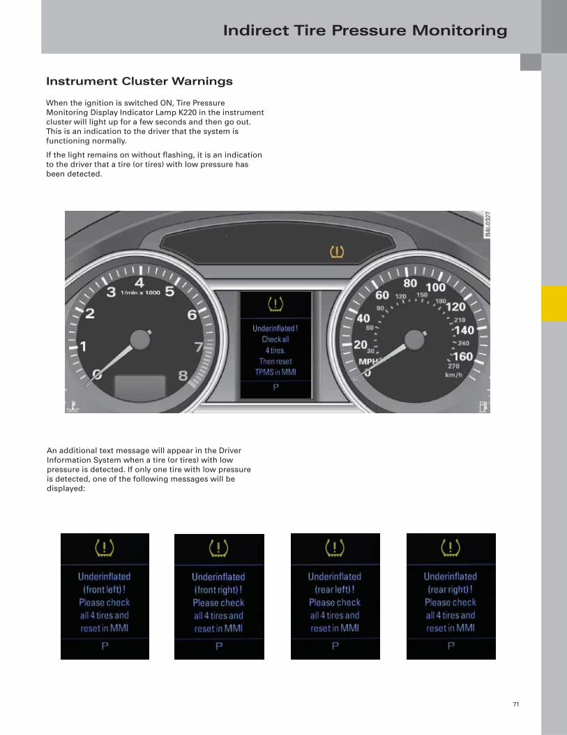
Indirect Tire Pressure Monitoring
71
Instrument Cluster Warnings
When the ignition is switched ON, Tire Pressure
Monitoring Display Indicator Lamp K220 in the instrument
cluster will light up for a few seconds and then go out.
This is an indication to the driver that the system is
functioning normally.
If the light remains on without fl ashing, it is an indication
to the driver that a tire (or tires) with low pressure has
been detected.
An additional text message will appear in the Driver
Information System when a tire (or tires) with low
pressure is detected. If only one tire with low pressure
is detected, one of the following messages will be
displayed:
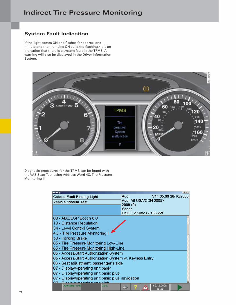
Indirect Tire Pressure Monitoring
72
System Fault Indication
If the light comes ON and fl ashes for approx. one
minute and then remains ON solid (no fl ashing,) it is an
indication that there is a system fault in the TPMS. A
warning will also be displayed in the Driver Information
System.
Diagnosis procedures for the TPMS can be found with
the VAS Scan Tool using Address Word 4C, Tire Pressure
Monitoring II.
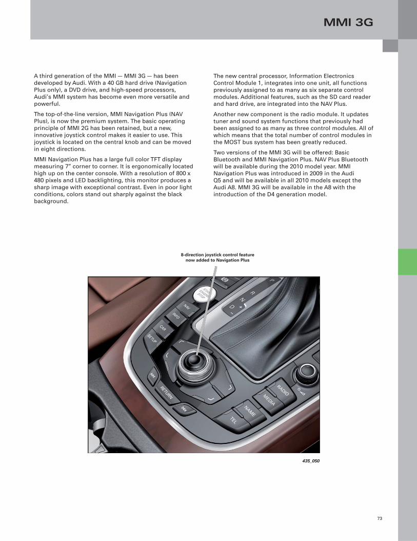
MMI 3G
73
The new central processor, Information Electronics
Control Module 1, integrates into one unit, all functions
previously assigned to as many as six separate control
modules. Additional features, such as the SD card reader
and hard drive, are integrated into the NAV Plus.
Another new component is the radio module. It updates
tuner and sound system functions that previously had
been assigned to as many as three control modules. All of
which means that the total number of control modules in
the MOST bus system has been greatly reduced.
Two versions of the MMI 3G will be offered: Basic
Bluetooth and MMI Navigation Plus. NAV Plus Bluetooth
will be available during the 2010 model year. MMI
Navigation Plus was introduced in 2009 in the Audi
Q5 and will be available in all 2010 models except the
Audi A8. MMI 3G will be available in the A8 with the
introduction of the D4 generation model.
A third generation of the MMI — MMI 3G — has been
developed by Audi. With a 40 GB hard drive (Navigation
Plus only), a DVD drive, and high-speed processors,
Audi’s MMI system has become even more versatile and
powerful.
The top-of-the-line version, MMI Navigation Plus (NAV
Plus), is now the premium system. The basic operating
principle of MMI 2G has been retained, but a new,
innovative joystick control makes it easier to use. This
joystick is located on the central knob and can be moved
in eight directions.
MMI Navigation Plus has a large full color TFT display
measuring 7” corner to corner. It is ergonomically located
high up on the center console. With a resolution of 800 x
480 pixels and LED backlighting, this monitor produces a
sharp image with exceptional contrast. Even in poor light
conditions, colors stand out sharply against the black
background.
8-direction joystick control feature now added to Navigation Plus
435_050
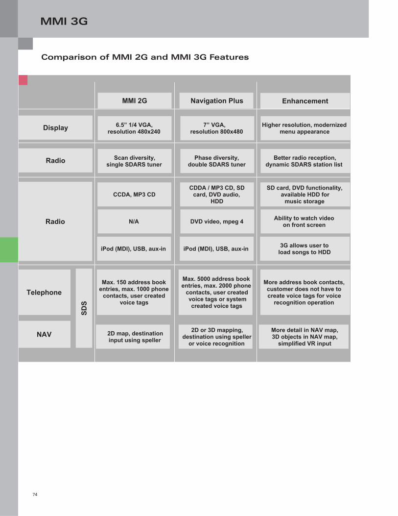
MMI 3G
74
Comparison of MMI 2G and MMI 3G Features
MMI 2G Navigation Plus Enhancement
6.5” 1/4 VGA, resolution 480x240
7” VGA, resolution 800x480
Higher resolution, modernized menu appearance Display
Radio Scan diversity, single SDARS tuner
Phase diversity, double SDARS tuner
Better radio reception,dynamic SDARS station list
CCDA, MP3 CD
CDDA / MP3 CD, SD card, DVD audio,
HDD
SD card, DVD functionality, available HDD for
music storage
N/A DVD video, mpeg 4 Ability to watch video on front screen
iPod (MDI), USB, aux-in
iPod (MDI), USB, aux-in 3G allows user to
load songs to HDD
Radio
SDS
NAV
Telephone
2D map, destinationinput using speller
2D or 3D mapping,destination using speller
or voice recognition
More detail in NAV map,3D objects in NAV map,
simplified VR input
Max. 150 address book entries, max. 1000 phone
contacts, user created voice tags
Max. 5000 address book entries, max. 2000 phone
contacts, user created voice tags or systemcreated voice tags
More address book contacts, customer does not have to create voice tags for voice
recognition operation
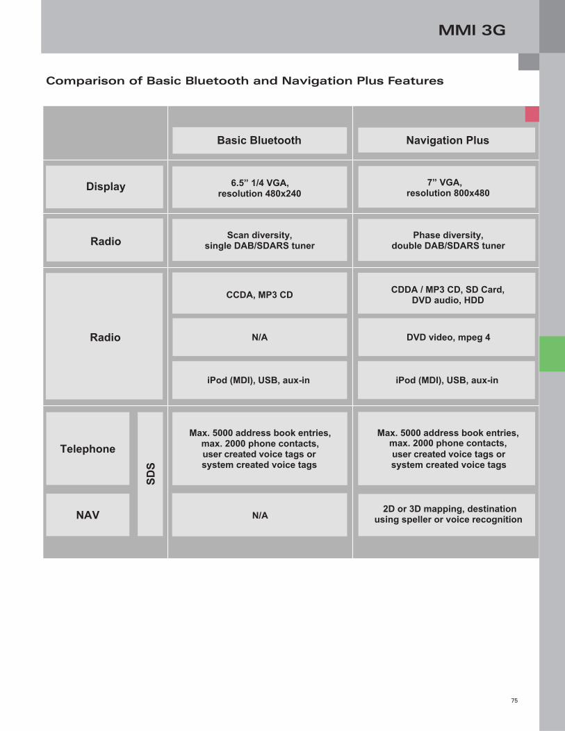
MMI 3G
75
Comparison of Basic Bluetooth and Navigation Plus Features
Navigation Plus
7” VGA, resolution 800x480 Display
Radio Phase diversity, double DAB/SDARS tuner
Basic Bluetooth
6.5” 1/4 VGA, resolution 480x240
Scan diversity, single DAB/SDARS tuner
CCDA, MP3 CD
CDDA / MP3 CD, SD Card,
DVD audio, HDD
N/A DVD video, mpeg 4
iPod (MDI), USB, aux-in
iPod (MDI), USB, aux-in
Radio
SDS
NAV
Telephone
N/A 2D or 3D mapping, destination
using speller or voice recognition
Max. 5000 address book entries, max. 2000 phone contacts, user created voice tags or system created voice tags
Max. 5000 address book entries, max. 2000 phone contacts, user created voice tags or system created voice tags
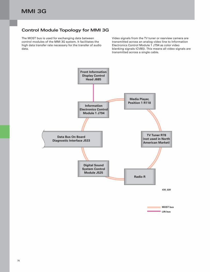
MMI 3G
76
Control Module Topology for MMI 3G
Video signals from the TV tuner or rearview camera are
transmitted across an analog video line to Information
Electronics Control Module 1 J794 as color video
blanking signals (CVBS). This means all video signals are
transmitted across a single cable.
The MOST bus is used for exchanging data between
control modules of the MMI 3G system. It facilitates the
high data transfer rate necessary for the transfer of audio
data.
435_020
Front Information Display Control
Head J685
Information Electronics Control
Module 1 J794
Media Player, Position 1 R118
Data Bus On Board Diagnostic Interface J533
Digital Sound System Control
Module J525Radio R
TV Tuner R78(not used in North American Market)
MOST bus
LIN bus

Notes
77
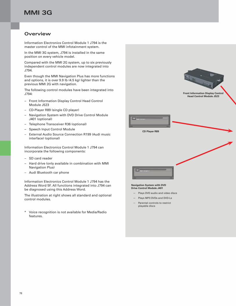
MMI 3G
78
Overview
Information Electronics Control Module 1 J794 is the
master control of the MMI infotainment system.
In the MMI 3G system, J794 is installed in the same
position on every vehicle model.
Compared with the MMI 2G system, up to six previously
independent control modules are now integrated into
J794.
Even though the MMI Navigation Plus has more functions
and options, it is over 9.9 lb (4.5 kg) lighter than the
previous MMI 2G with navigation.
The following control modules have been integrated into
J794:
– Front Information Display Control Head Control
Module J523
– CD-Player R89 (single CD player)
– Navigation System with DVD Drive Control Module
J401 (optional)
– Telephone Transceiver R36 (optional)
– Speech Input Control Module
– External Audio Source Connection R199 (Audi music
interface) (optional)
Information Electronics Control Module 1 J794 can
incorporate the following components:
– SD card reader
– Hard drive (only available in combination with MMI
Navigation Plus)
– Audi Bluetooth car phone
Information Electronics Control Module 1 J794 has the
Address Word 5F. All functions integrated into J794 can
be diagnosed using this Address Word.
The illustration at right shows all standard and optional
control modules.
* Voice recognition is not available for Media/Radio
features.
Front Information Display Control Head Control Module J523
CD Player R89
Navigation System with DVDDrive Control Module J401
— Plays DVD audio and video discs
— Plays MP3 DVDs and DVD-Ls
— Parental controls to restrict
playable discs
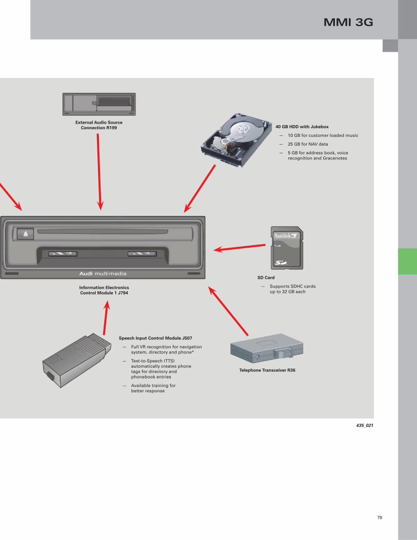
MMI 3G
79
435_021
Information Electronics Control Module 1 J794
External Audio Source Connection R199 40 GB HDD with Jukebox
— 10 GB for customer loaded music
— 25 GB for NAV data
— 5 GB for address book, voice
recognition and Gracenotes
Telephone Transceiver R36
Speech Input Control Module J507
— Full VR recognition for navigation
system, directory and phone*
— Text-to-Speech (TTS)
automatically creates phone
tags for directory and
phonebook entries
— Available training for
better response
SD Card
— Supports SDHC cards
up to 32 GB each
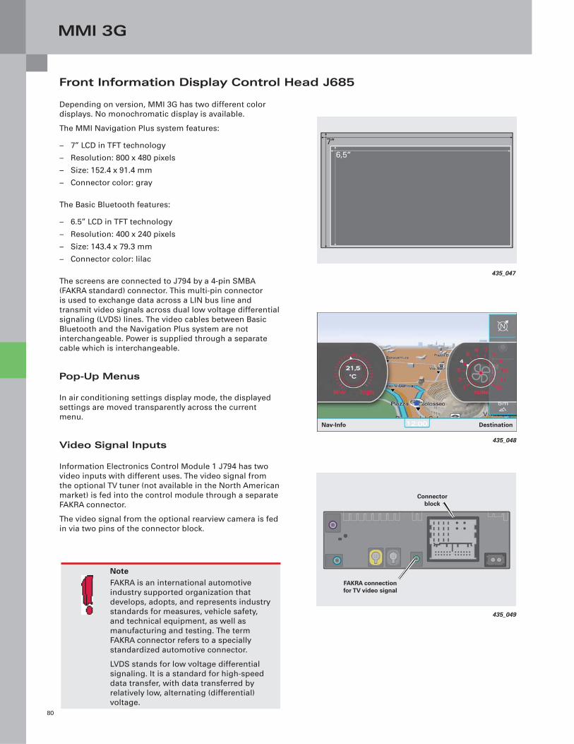
MMI 3G
80
Front Information Display Control Head J685
Depending on version, MMI 3G has two different color
displays. No monochromatic display is available.
The MMI Navigation Plus system features:
– 7” LCD in TFT technology
– Resolution: 800 x 480 pixels
– Size: 152.4 x 91.4 mm
– Connector color: gray
The Basic Bluetooth features:
– 6.5” LCD in TFT technology
– Resolution: 400 x 240 pixels
– Size: 143.4 x 79.3 mm
– Connector color: lilac
The screens are connected to J794 by a 4-pin SMBA
(FAKRA standard) connector. This multi-pin connector
is used to exchange data across a LIN bus line and
transmit video signals across dual low voltage differential
signaling (LVDS) lines. The video cables between Basic
Bluetooth and the Navigation Plus system are not
interchangeable. Power is supplied through a separate
cable which is interchangeable.
Pop-Up Menus
In air conditioning settings display mode, the displayed
settings are moved transparently across the current
menu.
Video Signal Inputs
Information Electronics Control Module 1 J794 has two
video inputs with different uses. The video signal from
the optional TV tuner (not available in the North American
market) is fed into the control module through a separate
FAKRA connector.
The video signal from the optional rearview camera is fed
in via two pins of the connector block.
435_047
435_049
Connector block
FAKRA connection for TV video signal
435_048
DestinationNav-Info
NoteFAKRA is an international automotive
industry supported organization that
develops, adopts, and represents industry
standards for measures, vehicle safety,
and technical equipment, as well as
manufacturing and testing. The term
FAKRA connector refers to a specially
standardized automotive connector.
LVDS stands for low voltage differential
signaling. It is a standard for high-speed
data transfer, with data transferred by
relatively low, alternating (differential)
voltage.
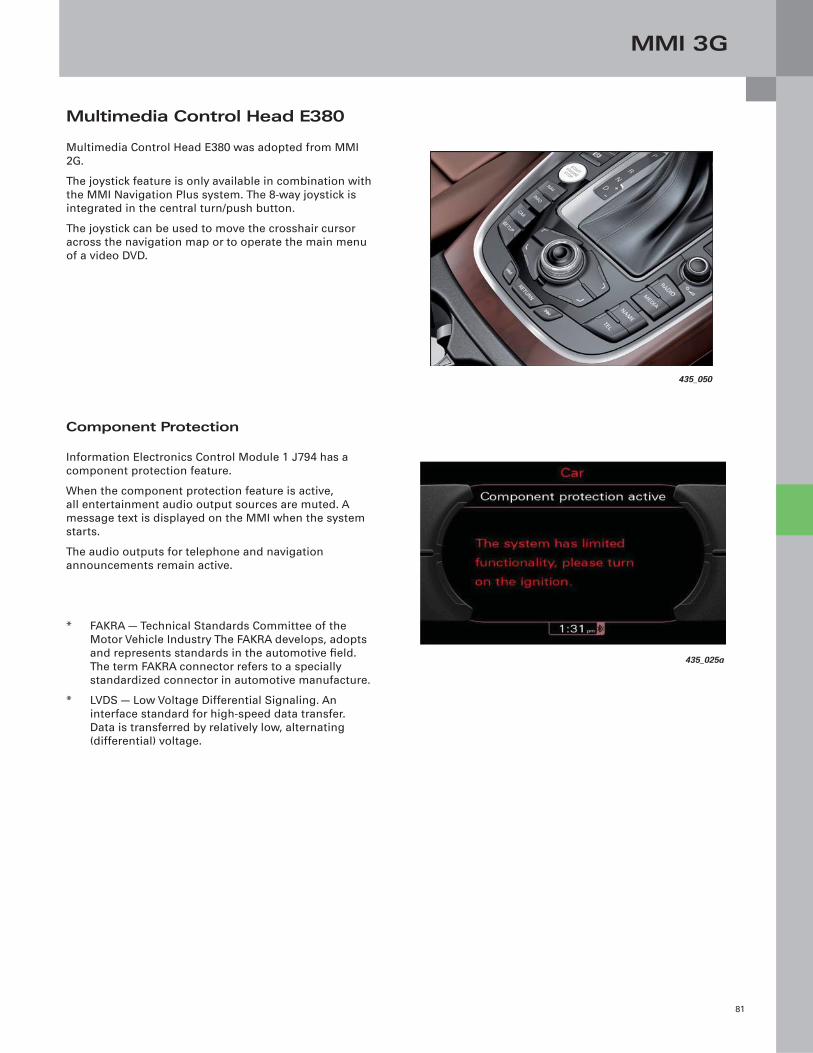
MMI 3G
81
Multimedia Control Head E380
Multimedia Control Head E380 was adopted from MMI
2G.
The joystick feature is only available in combination with
the MMI Navigation Plus system. The 8-way joystick is
integrated in the central turn/push button.
The joystick can be used to move the crosshair cursor
across the navigation map or to operate the main menu
of a video DVD.
Component Protection
Information Electronics Control Module 1 J794 has a
component protection feature.
When the component protection feature is active,
all entertainment audio output sources are muted. A
message text is displayed on the MMI when the system
starts.
The audio outputs for telephone and navigation
announcements remain active.
* FAKRA — Technical Standards Committee of the
Motor Vehicle Industry The FAKRA develops, adopts
and represents standards in the automotive fi eld.
The term FAKRA connector refers to a specially
standardized connector in automotive manufacture.
* LVDS — Low Voltage Differential Signaling. An
interface standard for high-speed data transfer.
Data is transferred by relatively low, alternating
(differential) voltage.
435_050
435_025a
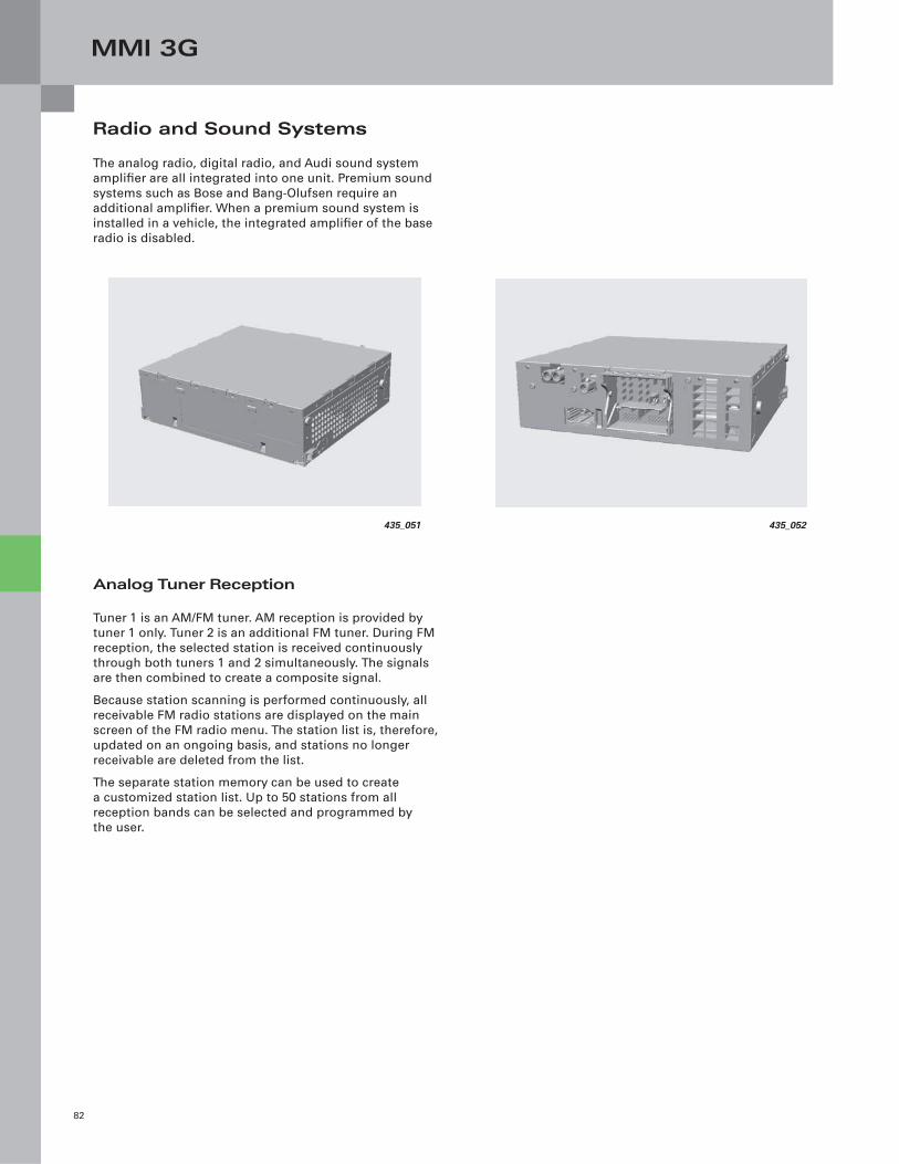
MMI 3G
82
Radio and Sound Systems
The analog radio, digital radio, and Audi sound system
amplifi er are all integrated into one unit. Premium sound
systems such as Bose and Bang-Olufsen require an
additional amplifi er. When a premium sound system is
installed in a vehicle, the integrated amplifi er of the base
radio is disabled.
Analog Tuner Reception
Tuner 1 is an AM/FM tuner. AM reception is provided by
tuner 1 only. Tuner 2 is an additional FM tuner. During FM
reception, the selected station is received continuously
through both tuners 1 and 2 simultaneously. The signals
are then combined to create a composite signal.
Because station scanning is performed continuously, all
receivable FM radio stations are displayed on the main
screen of the FM radio menu. The station list is, therefore,
updated on an ongoing basis, and stations no longer
receivable are deleted from the list.
The separate station memory can be used to create
a customized station list. Up to 50 stations from all
reception bands can be selected and programmed by
the user.
435_052435_051
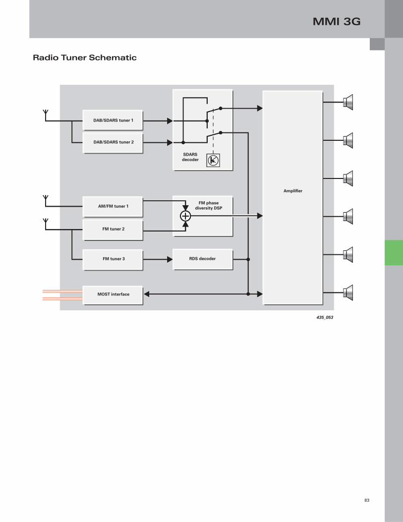
MMI 3G
83
435_053
Amplifi er
SDARS decoder
FM phase diversity DSP
RDS decoder
MOST interface
FM tuner 3
FM tuner 2
AM/FM tuner 1
DAB/SDARS tuner 2
DAB/SDARS tuner 1
Radio Tuner Schematic
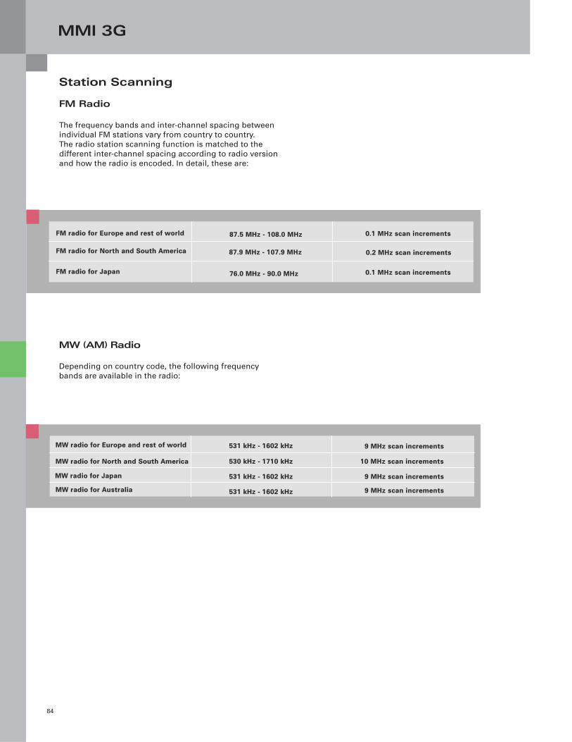
MMI 3G
84
FM Radio
The frequency bands and inter-channel spacing between
individual FM stations vary from country to country.
The radio station scanning function is matched to the
different inter-channel spacing according to radio version
and how the radio is encoded. In detail, these are:
Station Scanning
MW (AM) Radio
Depending on country code, the following frequency
bands are available in the radio:
FM radio for Europe and rest of world
FM radio for North and South America
FM radio for Japan
87.5 MHz - 108.0 MHz
87.9 MHz - 107.9 MHz
76.0 MHz - 90.0 MHz
0.1 MHz scan increments
0.2 MHz scan increments
0.1 MHz scan increments
MW radio for Europe and rest of world
MW radio for North and South America
MW radio for Japan
MW radio for Australia
531 kHz - 1602 kHz
530 kHz - 1710 kHz
531 kHz - 1602 kHz
531 kHz - 1602 kHz
9 MHz scan increments
10 MHz scan increments
9 MHz scan increments
9 MHz scan increments
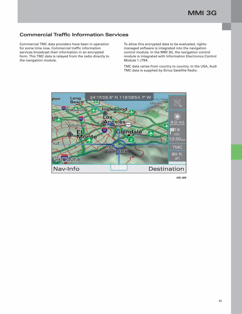
MMI 3G
85
Commercial Traffi c Information Services
Commercial TMC data providers have been in operation
for some time now. Commercial traffi c information
services broadcast their information in an encrypted
form. This TMC data is relayed from the radio directly to
the navigation module.
435_005
To allow this encrypted data to be evaluated, rights-
managed software is integrated into the navigation
control module. In the MMI 3G, the navigation control
module is integrated with Information Electronics Control
Module 1 J794.
TMC data varies from country to country. In the USA, Audi
TMC data is supplied by Sirius Satellite Radio.
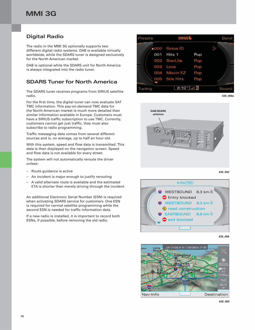
MMI 3G
86
Digital Radio
The radio in the MMI 3G optionally supports two
different digital radio systems. DAB is available virtually
worldwide, while the SDARS tuner is designed exclusively
for the North American market.
DAB is optional while the SDARS unit for North America
is always integrated into the radio tuner.
SDARS Tuner for North America
The SDARS tuner receives programs from SIRIUS satellite
radio.
For the fi rst time, the digital tuner can now evaluate SAT
TMC information. This pay-on-demand TMC data for
the North American market is much more detailed than
similar information available in Europe. Customers must
have a SIRIUS traffi c subscription to use TMC. Currently,
customers cannot get just traffi c, they must also
subscribe to radio programming.
Traffi c messaging data comes from several different
sources and is, on average, up to half an hour old.
With this system, speed and fl ow data is transmitted. This
data is then displayed on the navigation screen. Speed
and fl ow data is not available for every street.
The system will not automatically reroute the driver
unless:
– Route guidance is active
– An incident is major enough to justify rerouting
– A valid alternate route is available and the estimated
ETA is shorter than merely driving through the incident
An additional Electronic Serial Number (ESN) is required
when activating SDARS service for customers. One ESN
is required for normal satellite programming while the
second ESN is needed for traffi c information data.
If a new radio is installed, it is important to record both
ESNs, if possible, before removing the old radio.
435_056a
435_052
DAB/SDARS antenna
435_058
435_005

MMI 3G
87
Sound Systems
The Audi sound system consists of radio R, together
with an integrated six-channel amplifi er and a total of 10
speakers (11 speakers in the Audi Q7).
All speakers are connected to radio R. The radio receives
all audio signals from other control modules, such as the
CD changer, via MOST bus, relaying them to the speakers.
All diagnostic functions for the Audi sound system can be
found using Address Word 56.
All premium sound systems (Bose, Bang-Olufsen) have
external amplifi ers. The total number of speakers varies
from model to model. The amplifi ers were adopted
from the MMI 2G, with software adapted to the new
features of the MMI 3G. The accompanying speakers and
microphones for noise compensation are unchanged
compared with MMI 2G. For details of each sound system,
refer to the Self-Study Programs covering the respective
vehicles.
All diagnostic functions of the premium and advanced
sound systems can be found using Address Word 47.
Amplifi er in Radio
An audio amplifi er is integrated in radio R, depending on
sound system version. A separate amplifi er is, therefore,
not always necessary. The individual models are listed
below together with their sound systems and respective
amplifi ers.
Audi Sound System (standard)
A3, A4, A5, Q5, A6, Q7
Premium Sound System (Bose)
6-channel amplifier 180 watt amplifier power
External amplifier
A8, Q7
Premium Sound System (Bose)
External amplifier
Premium Sound System (Bang-Olufsen) Two external amplifiers
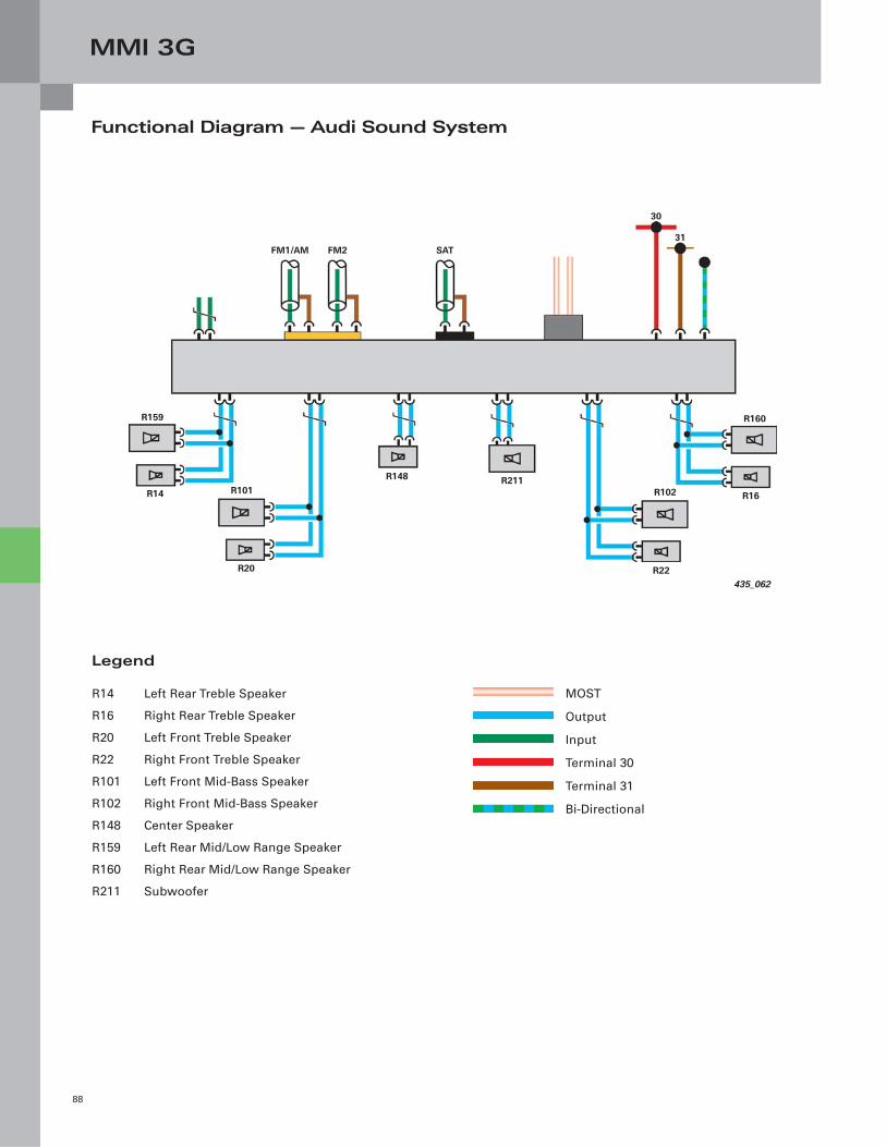
MMI 3G
88
Functional Diagram — Audi Sound System
Legend
R14 Left Rear Treble Speaker
R16 Right Rear Treble Speaker
R20 Left Front Treble Speaker
R22 Right Front Treble Speaker
R101 Left Front Mid-Bass Speaker
R102 Right Front Mid-Bass Speaker
R148 Center Speaker
R159 Left Rear Mid/Low Range Speaker
R160 Right Rear Mid/Low Range Speaker
R211 Subwoofer
MOST
Output
Input
Terminal 30
Terminal 31
Bi-Directional
435_062
R159
FM1/AM FM2 SAT
30
31
R160
R16R102
R22
R211R148
R14 R101
R20

MMI 3G
89
MMI 3G transfers audio from DVDs to premium sound
system amplifi ers through six separate audio channels.
This provides an authentic DVD sound experience.
All other media (CD, digital radio, FM radio, MP3) are
transferred to the amplifi er in stereo. If a surround setting
for stereo sources is selected in the MMI audio setup,
the signals to the surround speakers in the amplifi er
are slightly delayed compared with signals to the other
speakers. This creates an ambient effect unique to the
customer vehicle.
Surround Sound with DVD Playback
With DVD videos, the Dolby Digital, or DTS (Digital
Theatre System) audio format is often used for sound
reproduction. Both systems save audio signals to six
different channels. In technical terms, this is also known
as 5.1 multi-channel sound.
The individual channels are:
– Front left
– Front center
– Front right
– Rear left
– Rear right
– Subwoofer
5
1
5.1
Stereo 5.1 multi-channel
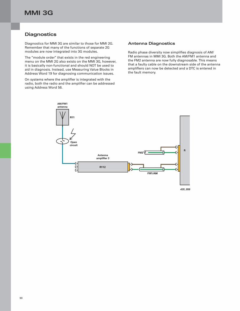
MMI 3G
90
Antenna Diagnostics
Radio phase diversity now simplifi es diagnosis of AM/
FM antennas in MMI 3G. Both the AM/FM1 antenna and
the FM2 antenna are now fully diagnosable. This means
that a faulty cable on the downstream side of the antenna
amplifi ers can now be detected and a DTC is entered in
the fault memory.
Diagnostics
Diagnostics for MMI 3G are similar to those for MMI 2G.
Remember that many of the functions of separate 2G
modules are now integrated into 3G modules.
The “module order” that exists in the red engineering
menu on the MMI 2G also exists on the MMI 3G, however,
it is basically non-functional and should NOT be used to
aid in diagnosis. Instead, use Measuring Value Blocks in
Address Word 19 for diagnosing communication issues.
On systems where the amplifi er is integrated with the
radio, both the radio and the amplifi er can be addressed
using Address Word 56.
435_059
AM/FM1 antenna
Antenna amplifi er 3
Open circuit
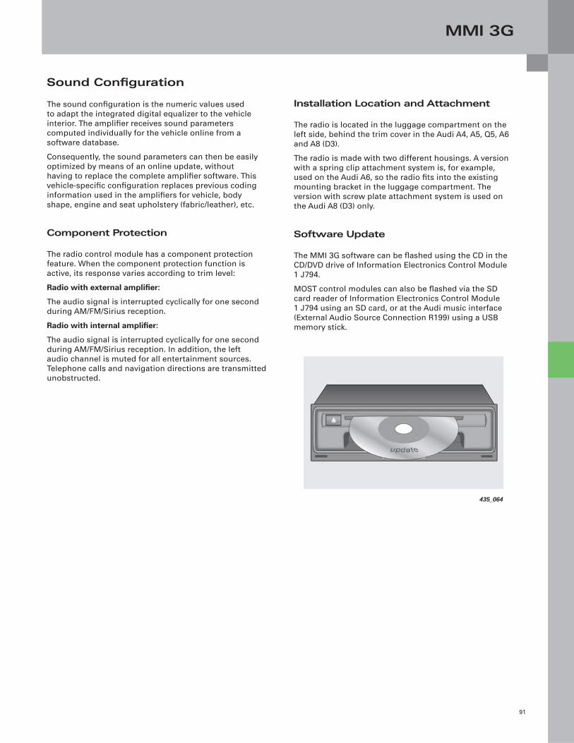
MMI 3G
91
Installation Location and Attachment
The radio is located in the luggage compartment on the
left side, behind the trim cover in the Audi A4, A5, Q5, A6
and A8 (D3).
The radio is made with two different housings. A version
with a spring clip attachment system is, for example,
used on the Audi A6, so the radio fi ts into the existing
mounting bracket in the luggage compartment. The
version with screw plate attachment system is used on
the Audi A8 (D3) only.
Software Update
The MMI 3G software can be fl ashed using the CD in the
CD/DVD drive of Information Electronics Control Module
1 J794.
MOST control modules can also be fl ashed via the SD
card reader of Information Electronics Control Module
1 J794 using an SD card, or at the Audi music interface
(External Audio Source Connection R199) using a USB
memory stick.
Sound Confi guration
The sound confi guration is the numeric values used
to adapt the integrated digital equalizer to the vehicle
interior. The amplifi er receives sound parameters
computed individually for the vehicle online from a
software database.
Consequently, the sound parameters can then be easily
optimized by means of an online update, without
having to replace the complete amplifi er software. This
vehicle-specifi c confi guration replaces previous coding
information used in the amplifi ers for vehicle, body
shape, engine and seat upholstery (fabric/leather), etc.
Component Protection
The radio control module has a component protection
feature. When the component protection function is
active, its response varies according to trim level:
Radio with external amplifi er:
The audio signal is interrupted cyclically for one second
during AM/FM/Sirius reception.
Radio with internal amplifi er:
The audio signal is interrupted cyclically for one second
during AM/FM/Sirius reception. In addition, the left
audio channel is muted for all entertainment sources.
Telephone calls and navigation directions are transmitted
unobstructed.
435_064
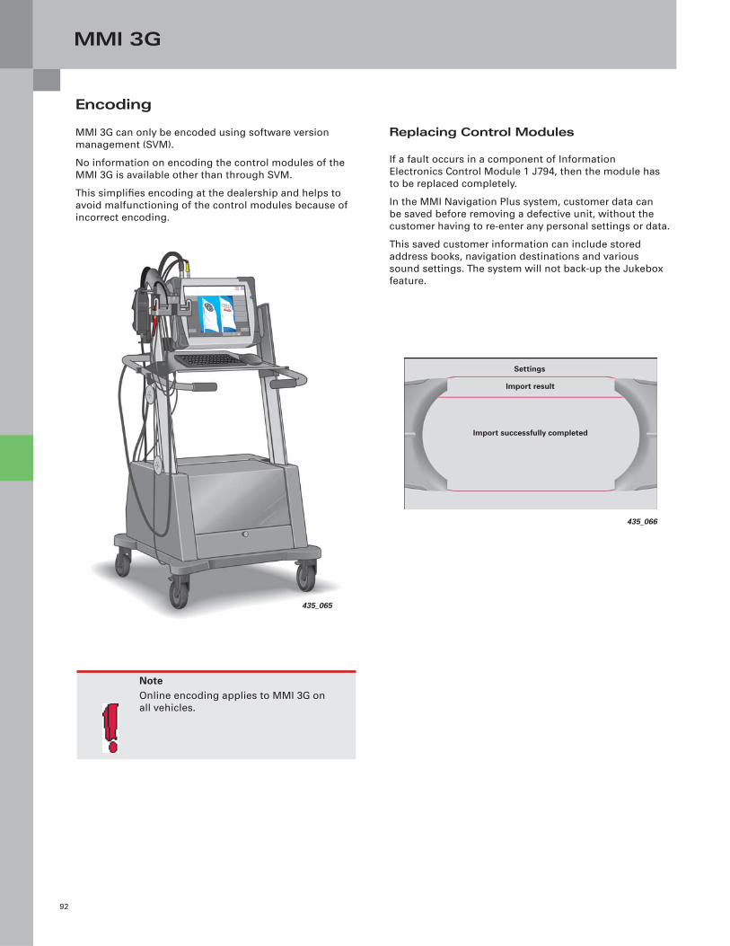
MMI 3G
92
Replacing Control Modules
If a fault occurs in a component of Information
Electronics Control Module 1 J794, then the module has
to be replaced completely.
In the MMI Navigation Plus system, customer data can
be saved before removing a defective unit, without the
customer having to re-enter any personal settings or data.
This saved customer information can include stored
address books, navigation destinations and various
sound settings. The system will not back-up the Jukebox
feature.
Encoding
MMI 3G can only be encoded using software version
management (SVM).
No information on encoding the control modules of the
MMI 3G is available other than through SVM.
This simplifi es encoding at the dealership and helps to
avoid malfunctioning of the control modules because of
incorrect encoding.
NoteOnline encoding applies to MMI 3G on
all vehicles.
435_065
435_066
Settings
Import result
Import successfully completed
Knowledge Assessment
93
An on-line Knowledge Assessment (exam) is available for this Self-Study Program.
The Knowledge Assessment may or may not be required for Certifi cation.
You can fi nd this Knowledge Assessment at:
www.accessaudi.com
From the accessaudi.com Homepage:
– Click on the “ACADEMY” tab
– Click on the “Academy Site” link
– Click on the “CRC/Certifi cation” link
– Click on Course Catalog and select “990193 — Audi New Technology 2009 – 2010”
For assistance please call:
Audi Academy
Certifi cation Resource Center (CRC)
1-877-283-4562
(8:00 a.m. to 8:00 p.m. EST)
Or you may send an email to:

990193
All rights reserved.Technical specifi cations subject to change without notice.
Audi of America, LLC2200 Ferdinand Porsche DriveHerndon, VA 20171