Self-powered Hammer Knife Rotor - Orec America Hammer Knife Rotor A H R 662 AHR662 pictured...
45
Self-powered Hammer Knife Rotor A H R 662 AHR662 pictured 0285-80000 ●Please fully read and understand all the important points highlighted in these operating instructions before operating this machine. ●When you purchase this machine, please ask the retailer to explain the safest way to operate it. ●Please keep these operating instructions and the warranty safe and close to hand so that they may be easily referred to at anytime. OREC America Inc. (To the retailer) Please inspect this machine before shipping it to the customer. Please send us Warranty Registration Card too.
Transcript of Self-powered Hammer Knife Rotor - Orec America Hammer Knife Rotor A H R 662 AHR662 pictured...

Self-powered Hammer Knife Rotor
A H R 662
AHR662 pictured 0285-80000
●Please fully read and understand all the important points highlighted in these operating instructions before operating this machine.
●When you purchase this machine, please ask the retailer to explain the safest way to operate it.
●Please keep these operating instructions and the warranty safe and close to hand so that they may be easily referred to at anytime.
OREC America Inc.
(To the retailer)
Please inspect this machine before shipping it to the customer. Please send us Warranty Registration Card too.

1
Getting Started Thank you for purchasing this machine. These instructions explain the correct and easy way to always keep
this machine in fine working order and operate it safely.
Please read these instructions fully before using this machine in order to understand the safest, most
efficient way of operating it, and the correct way to look after it.
Please keep these instructions in a safe place where they can be easily referred to at any time. We hope
you will use this machine for many years to come.
Furthermore, please understand that ongoing improvements in quality and performance, and other possible
parts changes may cause the actual machine to vary slightly from what is described in these instructions.
Machine Regulations This machine is designed to cut overgrown weeds and brush, it is not a lawn mower. Therefore it can not
offer the same quality cut as a finishing mower. This machine is not designed for built up areas but for
agricultural areas and mainly commercial users.
Definitions and Signs In these instructions, the following signs and definitions are used to indicate the level of danger that exists.
Please obey the following warnings and have a full understanding of the meaning of the signs.
Sign Definition
DANGERDisplayed when failure to obey instructions can result in death or serious
injury.
WARNING Displayed when there is a danger of death or serious injury.
CAUTIONDisplayed when failure to obey instructions can result in injury, or when not
attending to the machine and correcting it can also result in injury.
NOTICEDisplayed when it is important to know about operation and maintenance
specific to this machine, or at times when misunderstanding and mistakes are
common.

2
Contents For Safe Operation ............................................................................................ 3
Warning Signs .......................................................................................................................... 3
Important safety points ............................................................................................................. 5
How to Assemble Machine ............................................................................. 11
Name of Parts .................................................................................................. 12
Working of Each Part ...................................................................................... 13
How to Run the Machine Well ......................................................................... 15 Initial inspection before running the machine ......................................................................... 15
How to move the machine manually with the engine switched off .......................................... 15
How to start and stop engine ................................................................................................. 15
How to drive, change speed, turn, stop (park) ........................................................................ 19 How to load and unload using a truck .................................................................................... 21
How to Operate the Machine Well .................................................................. 22 How to cut weeds and brush ......................................................................................................... 22
Oil Parts Inspection, Replacement, and Lubrication ..................................... 24 Transmission oil lubrication, inspection, and replacement ...................................................... 24 Engine oil inspection, replacement, lubrication .................................................................... 25
How to Lubricate Each Part ............................................................................ 26
How to Inspect, Maintain, and Adjust Each Part ........................................... 27 How to clean the air filter ..................................................................................................... 27 How to inspect fuel pipes ..................................................................................................... 28
How to clean fuel valve .......................................................................................................... 28
How to inspect and adjust the spark plug ............................................................................... 29
How to adjust each wire and belt ........................................................................................... 30 Precautions in cold climate .................................................................................................... 32
Blade Inspection and Replacement................................................................ 33 How to inspect and replace the blades .................................................................................. 33
Regarding Long-Term Storage ....................................................................... 34
Specifications ................................................................................................. 35
Included Parts and Tools ................................................................................ 36
Consumable Parts ........................................................................................... 36
Periodic Voluntary Inspection Table .............................................................. 37
Self Diagnosis Table ....................................................................................... 39
Engine Defects and How to Manage Them .................................................... 40
CONFORMITY CERTIFICATE .......................................................................... 41
CONFORMITY DECLARATION ........................................................................ 41
MEASUREMENT OF VIBRATION ..................................................................... 41
PARTS SUPPLIMENT ...................................................................................... 42
LIMITED WARRANTY ...................................................................................... 43

3
For Safe Operation Please read these instructions regarding safety and operation before operating this machine.
In order for this machine to satisfactorily demonstrate its true performance, please perform maintenance
and inspection.
Warning Signs The warning signs are attached to the machine to draw attention to particularly serious dangers. Please be
sure to fully understand the meaning of each warning sign before operating this machine.
・ Read the safety and operating manual.
・ Do not operate the machine near people or animals.
Stand clear the machine.
・ Remove all objects that could be thrown by the mower blades. Beware of thrown
objects.
・ Before doing maintenance, remove the spark plug.
・ Keep body parts away from rotating parts.
・ Keep body parts away from the mower blades.
・ For the Engine
Read Engine instruction manual before using.
Pay attention to exhaust Gas, hot surfaces, and flammable gasoline.
(0214-72100)
・ Always wear safety glasses or goggles, and ear protection
while operating the machine. (0215-83200)
・ Do not use on slopes of more than 15° (0223-72900)

4
*Position of labels affixed to installed engine will be a little different.
In the case that these warning signs become difficult to see, please replace them so that they can be easily seen and understood.
NOTICE
(0220-70800)×2
(0220-70700)
(0220-70800)×2
(0304-71200)
(0304-71100) (0304-71200)

5
Important Safety Points
This machine is equipped with a high-powered engine and fast moving blades. Misuse of this
machine can result in serious injury or death. Before using this machine, please be sure to read
these instructions and understand and obey the following warnings.
Notes for the operator of this machine
The operator of this machine should fully read these instructions. You can safely use this
machine only after gaining a full understanding of its operation and safety use guidelines.
Operate this machine only after fully reading and understanding the included engine’s
instructions.
The operation and maintenance of this machine should only be performed by trained persons.
Do not allow children, expectant mothers or any untrained person to use this machine, accident
and injury can result. Furthermore, please check and observe local law which may place age
limits on the operation of machinery.
Do not operate if suffering from overwork or il lness or if under the influence of alcohol or drugs.
Accidents and injury can result.
When lending this machine to another person
When lending this machine to another person it is the owner’s responsibility that the following
measures are carried out.
The owner should explain how to operate the machine and get the new operator to fully read
these instructions. The owner should then guide the new operator until they have a
comprehensive understanding of the machine’s operation and safety guidelines. Furthermore,
the owner should lend these instructions to the new operator together with the machine.
When lending this machine to a person who can not read English, the owner should take
responsibility for fully explaining its safe operation.
The owner holds responsibility for the management of this machine, including checking that all
parts are correctly attached and that all functions are working correctly before lending it to
anyone.
Managing gasoline safely
Absolutely do not handle gasoline in the presence of l it cigarettes, naked flame, or other
sources of ignition. Gasoline is an extremely flammable liquid and its high volatility means there
is a danger of fire and explosions.
Do not use a type of gasoline other than that described. There is a danger of fire and
explosions.
Store gasoline and oil safely away from sources of flame and places where children can easily
reach. Accidents and injury can result.
Please refuel in a place that is well ventilated. As gasoline is a highly volatile substance, there
is a danger that you will feel unwell if you operate the machine in a poorly ventilated place.
WARNING
WARNING
WARNING
DANGER

6
Do not open the fuel cap while running the engine.
When refueling, be sure to stop the engine and allow it to cool down. There is a danger of
suffering burns.
When refueling, be sure not to fi l l the fuel tank over the maximum level. If you do overfil l the fuel
tank, remove fuel until it sits below the maximum level. Over-fueling can cause fire and other
accidents.
After refueling, securely close the fuel cap and store the machine in a safe place with no
sources of ignition. There is a danger of fire.
If you spill gasoline, move the machine a safe distance away without starting the engine.
Starting the machine in close proximity to a fuel spil l can result in a fire or other accident. Use
a waste cloth to wipe away the spill and dispose the cloth in a suitable manner.
Be sure to change your clothes immediately if they come into contact with gasoline. There is a
danger that any gasoline on your clothes could ignite or cause you to feel unwell.
Do not refuel in places such as inside a car or on a truck, they could move unexpectedly. Refuel
after placing your fuel container safely on the ground, away from vehicles. Fuel spills can cause
fire and other accidents.
When refueling from a truck or trailer, remove gas-powered refueling equipment from the
vehicle and refuel the machine on the ground. If this is not possible, refuel the machine with a
portable container rather than from a gasoline dispenser nozzle. Fuel spills can cause fire and
other accidents.
Do not remove the refueling nozzle from the fuel tank until you have finished refueling. Fuel
spills can cause fire and other accidents.
Caution when starting the engine
Do not modify the engine as this can cause accidents or explosions. You will bear responsibility
for any accidents or problems caused by modification. Also, trying to claim compensation in
such cases will be ineffective.
Do not try to alter the position of the engine governor or change the set rotation speeds.
Do not run the engine in a place that is poorly ventilated. Engine exhaust gas is odorless and
contains carbon monoxide which can cause death or serious injury.
Do not allow highly flammable substances near to the engine or the path of the exhaust gas as
this can cause a fire.
Do not touch the engine or muffler as they become extremely hot during operation and can
cause severe burns.
Do not allow weeds and leaves to accumulate in the engine, especially in the recoil cover, air
filter, and near to the muffler. Overheating and fire can result.
Ensure that the drive clutch and blade clutch are in the [OFF] position, the speed change lever
is in the [N] position, and the brake is ON, before starting the engine. Not taking precautions
when starting the engine can cause injury and accidents.
After starting the engine with the blade clutch and drive clutch in the [OFF] position, check the
V-belt to be absolutely certain that it is not moving. If the V-belt is moving even a little,
immediately switch off the engine and adjust the belt guard and the wire. Not taking precautions
can cause injury and accidents.
WARNING
DANGER

7
Caution when loading and unloading
When loading or unloading using a truck, proceed carefully and be certain to park on a flat and
safe surface. A truck moving suddenly could cause injury and accidents.
Attach a gently sloping ramp securely to the truck’s loading platform and lower the running of
the engine. The speed change lever should be put in the forward [1] position for loading, and in
the reverse [R] position for unloading. Proceed with caution as injury and accidents can be
caused by the machine tipping over or running out of control.
Before operating the machine
Absolutely do not try to modify this machine (including modification of the protective cover and
safety cover) as this can cause injury and accidents. You will bear responsibil ity for any
accidents or problems caused by modification. Also, trying to claim compensation in such cases
will be ineffective.
Do not needlessly change or tamper with the safety apparatus. Inspection should be performed
periodically to ensure the safety apparatus is working correctly.
For reasons of safety, use the recommended accessories and attachments that are best suited
to the ground you are working on and the type of work you are performing.
This machine can not be ridden, do not try to ride it or allow children or pets to ride on it. This
can cause injury to people/pets and damage to the machine.
Wear suitable clothing when operating this machine. Please wear the following items to protect
against injury and reduce the possibility of accidents.
Long sleeves, long pants Protective glasses
Non-slip shoes Gloves
Helmet Ear defenders
In particular, as cuffs and hems of loose clothing, and jewelry can become entangled in the
machine. Avoid wearing such items to help prevent injury and accidents. Long hair should be
tied up inside a helmet.
Ensure that no part of your body comes into contact with the moving blades of this machine.
There is the possibility of serious injury such as the severing of hands and feet.
Do not remove any parts of this machine that have been fitted as standard. To prevent
accidents, be sure to use all covers and parts in the same state as they have been fitted.
Be sure that there are no people, animals or vehicles close by. Not taking precautions can
cause injury and accidents.
Before starting, remove any rocks or branches that could be thrown and cause injury to
bystanders or damage to the machine.
When working in a dangerous area, erect markers stop you from mistakenly getting too near to
obstacles, ditches, soft path edges, slopes (over 15°), or uneven ground.
Display a (MOWING) sign and erect a guard rope to prevent people (especially children) from
coming within 100FEET of the machine.
Use this machine during daylight or with sufficient artificial l ight. Do not operate this machine
at night when poor visibility will not allow you to have a complete grasp of your surroundings.
Not being able to notice dangerous objects and bystanders is a cause of injury and accidents.
Absolutely do not operate this machine in places where there are dangerous drops, ditches or
embankments. Accidents can be caused by the machine tipping over.
Do not use this machine on wet grass. It is easy to slip on wet grass, causing injury and
accidents.
WARNING
WARNING

8
Caution during operation
During operation, blades, chains and belts are hidden by a cover, be sure to keep hands and feet well
away. Touching these parts can cause serious injury such as the severing of hands and feet.
Do not operate the machine with the safety cover raised. There is a danger of injury and damage,
especially at the front of the machine, from rocks and other debris being thrown from the blades.
This machine is designed to minimize flying debris but there is the possibility of flying debris coming
out of the front cutting structure. For this reason, do not work under the assumption that debris cannot
fly out and hit people and property.
When mowing, always proceed forward in gear [1] or [2], never in reverse [R]. This not only decreases
the performance of the machine but also increases the likelihood of flying debris.
During operation, the rotating blades come right to the edge of the blade cover. Absolutely do not put
your hands inside the cover to try to clear weeds, etc. Not taking precautions can cause injury.
Do not raise the front cover while the blades are moving.
Before removing entangled weeds or other foreign objects from the blades, be sure to stop the engine
and remove the spark plug cord. Check that the blades have stopped moving before carefully
removing any entangled material.
Be sure that there are no people, animals or vehicles close by. When operating this machine, always
maintain a distance of 100 FEET between you and bystanders. If people or animals come near,
release the blade clutch and switch off the engine. Not taking precautions can cause injury and
accidents.
For safety reasons, do not make sudden starts/stops or sharp turns.
Take care to move and turn the machine gently. Furthermore, stop the blades when not cutting weeds
or brush. Not taking precautions can cause injury and accidents.
The person using this machine should always operate it from behind (handlebar side).When this
machine’s engine is running, do not stand in front of the path where you are cutting weeds or brush or
try to cut sideways. Not taking precautions can cause injury and accidents.
If you notice any strange noises, smells or heat/vibrations during the operation of this machine, switch
off the engine immediately, remove the spark plug cord and ensure that all movable parts have
completely stopped. Be sure to have the machine inspected for damage and obstructions and have
any damaged parts repaired.
Look out for holes in the ground and protruding tree roots. Also look out for obstructions that could be
hidden in long weeds or brush. The handlebars can be taken from your control, causing injury and
accidents.
Be careful when approaching blind corners, bushes, and trees which block your line of sight. Such
obstructions can hide children and animals from view.
Do not operate this machine in the direction of rivers and drop-offs, people and buildings. Accidents
can be caused by falls and collisions.
When moving the machine backwards, check that there are no people or obstacles behind you and
that you have a secure foothold. When reversing, there is a danger of being trapped between the
machine and a wall or falling from drop-offs.
Exercise caution when operating the machine alongside fences, buildings and trees. The machine’s
handlebars can be taken from your control if you come into contact with obstacles, possibly causing
injury and accidents.
Do not leave the machine unattended with the engine running. When leaving the machine unattended,
park on a flat surface with the engine switched off, put the speed change lever in [N] and confirm that
the parking brake is ON. Injury and accidents can be caused if the machine moves while unattended.
WARNING

9
When operating the machine close to buildings, shrubs and trees, take care not to cause
accidents and damage by crashing into them. If you do hit something, switch off the engine
immediately. Confirm that the blades have stopped moving and then check them for damage
such as bending and twisting. After verifying that the blades have stopped, check for damage
such as bending and twisting of the blades. Check all areas of the machine for damage and
have parts repaired or replaced if necessary.
Using the machine on slopes
When operating on slopes, serious accidents can be caused by you slipping and the machine
rolling over. Be especially careful when working in such areas and stop operating the machine
immediately if you feel in any danger at all.
Do not operate the machine on slopes of more than15°.
Mow across the face of slopes; never up and down. Exercise extreme caution when changing
direction on slopes.
When changing direction on a slope, do it slowly and carefully. The machine could roll over
causing injury and accidents.
Do not operate the machine on wet slopes. It is easy to slip on wet grass and suffer injury and
accidents.
Look out for holes in the ground and protruding tree roots. Also look out for obstructions take
could be hidden in long weeds and brush. The handlebars can be taken from your control,
causing injury and accidents.
When operating on slopes, do not leave the machine with its clutch off or the speed change
lever in neutral. The machine could run out of control, causing injury and accidents.
Children
When operating this machine, be particularly aware of children. Children are often interested in
mowers and may be drawn to you. As children may not be concentrating on their surroundings,
tragic accidents can occur if you take you eyes off them. Please treat the following points with
great care.
Do not allow children to come into the area where you are working. Make sure that young
children are securely in the care of an adult other than the operator.
Switch off the engine immediately if children enter the area where you are working.
Do not allow children to operate the machine. Furthermore, check and obey local law which
may place age limits on the operation of machinery.
Be careful when approaching blind corners, bushes, and trees which block your line of sight.
Such obstructions can hide children from view.
CAUTION
WARNING
WARNING

10
Maintenance
Be sure to switch off the engine and remove the spark plug cord before performing any
inspection, adjustment or maintenance on this machine.
When performing inspection, adjustment or maintenance, use tools such as a jack in order to
work as safely as possible.
Perform periodic inspection in order to work as safely as possible. If you discover any worn or
damaged parts, please replace them with recommended parts only.
This machine is equipped with extremely sharp blades. When inspecting or handling the
machine, do not directly touch the blades. Exercise caution by wearing gloves and wrapping
the blades in cloth. Furthermore, if you notice any abnormalities in the blades, do not try to
repair them but have them replaced. Not taking this precaution can cause injury and accidents.
Damage to the belt cover, blade cover, or flying debris prevention cover, could cause injury or
accidents. Be sure to have any damaged parts replaced before using the machine again.
Be sure to check that the covers of rotating parts are refitted correctly in their original positions
after being removed. Poorly fitted covers could open during operation and cause serious
injury.
Check that all nuts and bolts are securely tightened.
Perform comprehensive inspection and adjustment of such parts as drive clutch, blade clutch,
brake, throttle, and gear change.
When rubber fuel lines become old, they can split and dangerous fuel leaks can occur. Change
rubber parts if they split or every 3 years regardless of damage. At this time, also change the
fastening bands for the new parts.
Be sure to check that the bolts in the wheels and blades are tightly fastened. Make sure that
the detachable cover used for changing the blades is closed before operating the machine.
When replacing the blades, also replace the attached nuts and bolts. There is a possibility of
accidents caused by worn or damaged parts. Never substitute nuts and bolts with those that
are not recommended.
Remove fuel when storing or transporting the machine. Accidents and damage can be caused
by fuel spills or putrid fuel.
When storing the machine, place it on a flat surface away from sources of flame. Not taking
precautions can cause accidents and damage.
Before storing the machine, remove such foreign material as weeds and leaves. Clean away
any oil spills or fragments stained with oil.
Make sure that the engine has completely cooled before covering the machine with a storage
cover.
Depending on operating conditions, there may be occasions when incidents arise which are not
covered by the warnings in this manual. The operator should always use common sense and put
safety first when using this machine.
WARNING
11
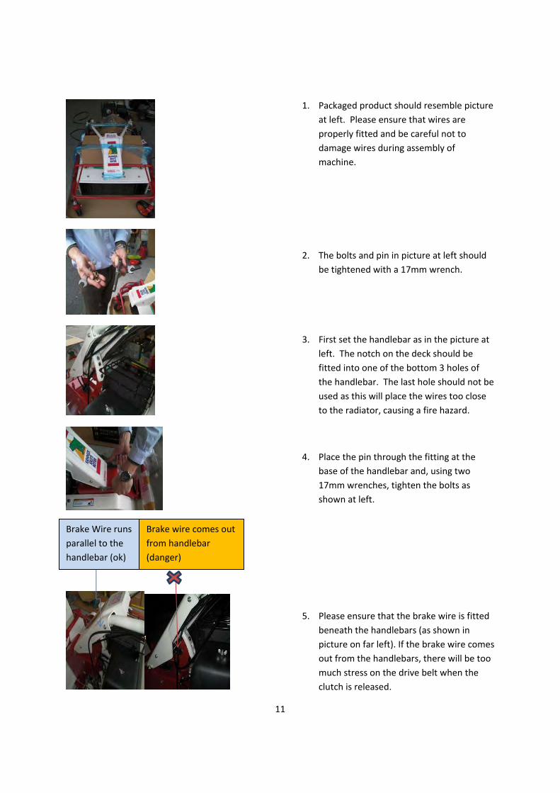
1. Packaged product should resemble picture
at left. Please ensure that wires are
properly fitted and be careful not to
damage wires during assembly of
machine.
2. The bolts and pin in picture at left should
be tightened with a 17mm wrench.
3. First set the handlebar as in the picture at
left. The notch on the deck should be
fitted into one of the bottom 3 holes of
the handlebar. The last hole should not be
used as this will place the wires too close
to the radiator, causing a fire hazard.
4. Place the pin through the fitting at the
base of the handlebar and, using two
17mm wrenches, tighten the bolts as
shown at left.
5. Please ensure that the brake wire is fitted
beneath the handlebars (as shown in
picture on far left). If the brake wire comes
out from the handlebars, there will be too
much stress on the drive belt when the
clutch is released.
Brake Wire runs
parallel to the
handlebar (ok)
Brake wire comes out
from handlebar
(danger)

12
Name of Parts
(1) Drive clutch lever
(2) Blade clutch lock lever
(3) Blade clutch lever
Throttle lever
(10) Steering clutch lever
(4) Speed change lever
(5) Cutting height adjustment lever
(6) Front wheels
(7) Handlebar up/down lever
(9) Engine stop switch
Front guard
Drive tires
(8)Front flappers

13
CAUTION
Working of Each Part
(1) Drive clutch lever Operates by turning power transmission [ON]/ [OFF] from the engine to the drive transmission.
Lower the lever and grip it together with the handlebars to transfer power to the transmission and start driving the
machine [ON]. To stop the machine, release your grip on the lever and it will automatically return to its raised position, power
transmission will be cut and the machine will stop.
(2) Blade clutch lock lever (3) Blade clutch lever Operates by turning power transmission [ON] / [OFF] between the engine and blades.
To start the blades rotating, first, lower the blade clutch lock lever (2) and grip the handlebars.
Next, raise the blade clutch lever (3) until it is in the lock position.
To stop, release your grip on the blade clutch lock lever (2) and the blade clutch lever will automatically return
to its lowered position. Power transmission to the blades will be cut and rotation will stop.
Regardless of the position of the drive clutch lever, the blades will continue to rotate at high speed if the blade clutch lever is raised [ON] while the engine is running. Show sufficient caution
regarding lever operation.
(4) Speed change lever Use this lever to select drive speed. There are 3 speed levels, 1 to 3, 1 reverse gear, and also neutral [N].
The position and speed of each lever is as follows.
Forward Reverse
1 2 3 1
Speed(mph 0.56 1.17 2.06 0.56
To operate speed change, be sure to put the drive clutch lever in the [OFF] position and allow
the machine to stop.
WARNING
14
CAUTION
(5) Cutting height adjustment lever
This lever adjusts the height at which weeds and brush are cut.
Turn the lever to the right to lower the cutting height and turn the lever left to raise the cutting height. When working on uneven ground, adjust the cutting height so that the blades do not cut into mud or rocks.
If the cutting height is too low, there is the danger of the following harmful effects. If you see any of the following symptoms, the cutting height is too low and needs to be raised.
-An increase in flying debris such as rocks.
Cutting into mud, thrown mud is stuck to the inside of the blade cover and the ejection of
cut weeds, etc, is getting worse, resulting in a wasteful loss of power output.
-Wear and tear of the blades occurs extremely quickly. Blades soon break.
(6) Front wheels
The front wheels run freely, enabling smooth steering on level ground.
(7) Handlebar up/down lever Adjust the height of the handlebars in accordance with the operator’s size or the type of work being performed.
Please adjust the handlebar position to the height of the operator’s hips.
(8) Front flappers The front flappers automatically open and close according to the quantity of weeds. Always operate with the
front flapper in a free state. Do not operate with the front flappers in the raised position.
(9) Engine stop switch Switches the engine power (ON)/(OFF).
(10) Steering clutch lever
Grip the left clutch lever to turn left and grip the right clutch lever to turn right.

15
How to Run the Machine Well
Initial inspection before running the machine(Please refer to the engine use manual)
In order to operate in safety and comfort, please refer to the [Periodic voluntary inspection table] on page 35. Please have any defective parts repaired straight away, before operating the machine again.
How to move the machine manually with the engine switched off
1. Put the speed change lever in the [N] position. 2. Grip the drive clutch lever [ON] and push the machine forward.
How to start and stop the engine
Do not start the engine in a confined space or a place with insufficient ventilation. Engine exhaust gas is odorless and contains carbon monoxide which can cause death.
Absolutely do not handle gasoline in the presence of lit cigarettes, naked flame, or other sources of
ignition. Gasoline is an extremely flammable liquid and its high volatility means there is a danger of fires
and explosions.
Ensure that the drive clutch and blade clutch are in the [OFF] position, the speed change lever is in the
[N] position, and the brake is ON, before starting the engine. Not taking precautions when starting the
engine can cause injury and accidents.
Fully read the caution and danger labels which have been attached to this machine.
Before starting the engine
Place the machine on a flat surface and perform the following procedures to check the quantity of engine oil
and fuel.
Prep 1 :Check engine oil
Make sure the engine has cooled down before checking oil. There is a danger of burns.
This machine is shipped without oil inside. Be sure to put oil in before starting the engine, even if there are
traces of residual oil in the engine left over from factory testing. Inspect with the engine horizontal and do not screw in the dipstick. Please use good quality, new engine oil of SD level or higher.
・Engine oil: SAE10W-30
DANGER
WARNING
NOTICE
WARNING

16
1. Unscrew the oil cap with attached oil gauge. 2. Check the oil level.
If the oil does not lie between the upper level and lower level, replenish to bring the oil to the upper level.
Prep 2 :Check transmission oil
This machine is shipped without oil inside. Be sure to put oil in before starting the engine, even if there are
traces of residual oil in the engine left over from factory testing. Inspect with the whole machine horizontal
Please use good quality, new proper transmission oil. ・Transmission oil: SAE80W-90
Prep 3 :Check fuel
Absolutely do not handle gasoline in the presence of lit cigarettes, naked flame, or other sources of ignition.
Gasoline is an extremely flammable liquid and its high volatility means there is a danger of fires and
explosions.
Please refuel in a place that is well ventilated. As gasoline is a highly volatile substance, there is a danger that
you will feel unwell if you operate the machine in a poorly ventilated place.
When refueling, be sure to stop the engine and allow it to cool down. There is a danger of suffering burns.
When refueling, be sure not to fill the fuel tank over the maximum level. If you do overfill the fuel tank, remove
fuel until it sits below the maximum level. Over-fueling can cause fire and other accidents.
After refueling, securely close the fuel cap and store the machine in a safe place with no sources of flame.
There is a danger of fire.
If you accidentally spill gasoline, move the machine a safe distance away without starting the engine. Starting
the machine in close proximity to a fuel spill can result in fire or other accident. Use a cloth to wipe away
waste gasoline then dispose in a suitable manner.
When working on slopes, avoid fuel spillage by making sure fuel is below the maximum level on the
inside of the refueling neck.
1. Refuel the machine with regular gasoline. 〈Refer to fuel tank specifications on quantity, page 33〉
2. After refueling, securely close the fuel cap.
WARNING
DANGER
Fuel filler cap
Fuel tank
Oil gauge

17
How to start the engine
1. Move the fuel valve lever to the [ON] position.
2. Turn the throttle lever to the [ (HI)] position.
3. Confirm the drive clutch lever and blade clutch lever are the [OFF] position.
4. To start a cold engine,move the choke lever to the [closed] position.
If the engine has been warmed up,
there is no need to use the choke.
5. Push and move the engine switch to the [ON] position.
Drive clutch lever OFF Blade clutch lever OFF
Throttle lever
NOTICE
Engine switch
ON OFF

18
6. Grip the starter knob, pull slowly until you feel tension and then pull strongly from this position. Immediately after the engine has started, slowly return the start knob to its original position.
7. If the choke lever to was moved to the [CLOSED] position to start theengne,gradually move it to the [OPEN] position as the engine warms up.
How to stop the engine
1. Turn the throttle lever to the [ (LOW)] position.
2. Push the engine switch to the [OFF] position to allow the engine to stop.
Turn the fuel valve lever to the [OFF] position.
Do not touch the hot engine immediately after switching off. Allow time for it to cool
down as there is a danger of burns.
Throttle lever
WARNING
Recoil starter
Engine switch
ON OFF

19
Drive clutch lever
CAUTION
How to drive, change speed, turn, stop (park)
Confirm that all around you is safe before proceeding to drive the machine. - If driving the machine alongside ditches or the edges of paths, there is a danger that the weight of the
machine could cause the ground to collapse. Exercise sufficient caution when operating the machine
on soft ground. - Do not operate the machine on slopes of more than 20°. There is a danger of the machine rolling over
or running out of control.
- Danger exists if you suddenly release the drive clutch while driving at high speed [ (HI)] with the throttle lever, as the emergency brake will be initiated. Put the throttle lever to [ (LOW)] and
lower the speed of the machine before stopping.
How to drive
1. Start the engine. (Refer to page 15 for how to start the engine)
2. Be sure to put the speed change lever securely in the necessary position.
If the speed change lever is not securely in place, there is a real danger that gears could be released while driving the machine. If a gear is difficult to engage, do not force it. Shift the drive clutch a little to the [ON] position and be certain to check the gear change one more time.
There are 3 forward speeds. Do not operate at excessive speeds.
3. Put the throttle lever in the [half open] position and grip the drive clutch lever [ON] to drive the machine.
Before driving, adjust the cutting height so as to avoid contacting the ground and other obstacles. Also be sure to have the blade clutch lever in the [OFF] position.
Speed change lever
WARNING
WARNING

20
CAUTION
CAUTION
How to change speed
1. Release the drive clutch lever [OFF].
Do not try to change speed with the drive clutch lever [ON]. This can cause injury and accidents.
2. Be sure to put the speed change lever securely in the
necessary position. Refer to ‘How to drive’ (page 17).
If the speed change lever is not securely in place, there is a real danger that gears could be released while driving the machine. If a gear is difficult to engage, do not force it. Shift the drive clutch a little to the [ON] position and be certain to check the gear change one more time.
3. Grip the drive clutch lever to the [ON] position and start off
again.
How to turn
1. Grip the left clutch lever to turn left and grip the right clutch lever to turn right.
How to stop (park)
1. Release the drive clutch lever [OFF] and allow the machine to stop. The parking break is engaged at the same time.
2. Allow the engine to stop.
〈Refer to ‘How to stop the engine’ page 16.〉
When parking, put the speed change lever in the neutral [N] position.
Always park the machine on flat, open ground with no obstacles nearby. By putting the drive clutch lever in the [OFF] position, the parking break will be initiated regardless of
the position of the speed change lever.
Speed change lever
「N」position
NOTICE
WARNING

21
How to load and unload using a truck
Park your truck on a flat and stable surface. Switch off your truck’s engine, engage reverse gear, and pull the parking brake. Also place chucks under your truck’s wheels to stop it from moving.
Before loading or unloading, raise the height of the blades so that they can not contact the ramp. There is a danger of the blades catching on the ramp, possibly causing the machine to roll over.
Attach the ramp’s hook so that there is no bump where it attaches to the truck’s loading bed. Also make sure that the ramp is securely attached.
Take sufficient care when the machine crosses from the ramp to the truck’s loading bed and the location of the center of gravity is suddenly changed.
Do not stand on the front of the machine. Do not operate any of the machine’s levers while on the ramp as there is a danger of the machine
rolling over. Make sure that the rubber crawler tracks on either side of the machine are positioned centrally on the
ramp. When loading and transporting by truck, engage the machine’s parking break and secure the machine
in the loading bed with a rope that is sufficiently strong enough. Also place chucks under the machine’s wheels to stop it from moving.
How to load and unload
1. Park your vehicle on a flat surface with no dangerous objects nearby.
2. Attach a ramp which conforms to the below standards.
3. Put the throttle lever in the intermediate position between
[ (HI)] and [ (LOW)].
4. Only load the machine in forward gear [1] and only unload in
reverse [R]. Do not use any other gear.
Ref: Ramp standards Make sure that your ramp is comprised of materials strong enough to conform to the following standards.
Length: 3.5 times longer than the truck’s loading bed is high. Width: At least as wide as the wheel span of the machine. Strength: Sufficiently strong enough to take the weight of the sum total of the
machine and the operator. Surface: Use a ramp with a non-slip surface.
WARNING
Use of side clutch is
strictly prohibited.

22
How to Operate the Machine Well
How to cut weeds and brush
Please again read the safety precautions (pages 4-9) and confirm the points regarding your work environment and general safety.
When using the machine for the first time, choose a flat area free from rocks and foreign objects and slowly cut a path by going over the area in a straight line.
If the engine stops dues to a large quantity of weeds, etc, you may need to mow the area twice. Mow one time at a reduced work speed with the blades set higher than usual to avoid damaging the machine. Mow for a second time with the blades set lower when you are confident you have reduced the weeds to a more manageable length,
When mowing, always proceed forward in gear [1] or [2], never in reverse [R]. This not only decreases the performance of the machine but also increases the likelihood of flying debris.
1. Adjust the cutting height using the cutting height adjustment lever.
At first, adjust the blades a little high, then readjust the height to best suit the conditions while you are working.
2. Start the engine.
Refer to ‘How to start the engine’ (page 15). 3. Use the handlebar up/down lever to adjust the handbars to best suit
the type of work being performed and also the size of the person operating the machine.
Be sure to stop working before making adjustments using the handlebar up/down lever.
4. Be sure to put the speed change lever securely in the necessary
position.
At first, position the blades a little high, then readjust the height to best suit the conditions after performing some test cuts.
If the speed change lever is not securely in position, there is a real danger that gears could be released while driving the machine. Without forcing too hard, shift the drive clutch a little to the [ON] position and check again that the lever is securely in position.
Cutting height
adjustment lever NOTICE
WARNING
Speed change lever
NOTICE
NOTICE
Handlebar up/down lever

23
5. Turn the throttle lever [1] to the [ (HI)] position, grip the blade clutch lock lever [2], and gently raise the blade clutch lever [3] to the [ON] position. You may stall the engine if you pull the blade clutch lever up up suddenly.
Take sufficient caution as the blades are now rotating.
6. Gently grip the drive clutch lever together with the handlebar and start work.
How to stop
If you want to leave the machine unattended, be sure to switch the engine off, put the speed change lever in the [N] position and confirm that the parking brake is ON. Accidents and damage can be caused by an unattended machine running out of control.
1. Release your grip on the drive clutch lever [OFF] an allow the
machine to stop. The parking brake is automatically engaged at the same time.
2. Release your grip on the blade clutch lever. At the same the blade
clutch lever is released, the blade brake is automatically engaged. The blades stop rotating after a short time (about 3 to 5 seconds).
3. Stop the engine.
Refer to ‘How to stop the engine’ (page 16).
WARNING
WARNING
2
3
1

24
Oil Parts Inspection, Replacement, and Lubrication
When this machine is shipped, it is not lubricated with oil. Before operating the machine, make
sure that it is lubricated with the described oil, in the described parts, and in the described
quantities. To always operate this machine in good condition, perform oil changes periodically.
When performing inspection, replacement, or lubrication of oiled parts, place the machine on a
flat, open surface. Switch on the engine and warm it up to confirm it is working properly. Then switch off the engine, allow it to cool down and remove the spark plug cord.
After switching off, please wait at least 5 minutes for all parts to cool down sufficiently before you touch the machine. Immediately after the engine has stopped, the body will be very hot and
can cause burns if touched.
After switching off the engine, oil will still be in the engine and transmission so the quantity of oil
remaining will not be exactly displayed.
After changing the oil, please dispose of waste oil appropriately.
Transmission oil lubrication, inspection, and replacement
Inspection
Remove the oil inlet plug from the upper part of the transmission case on the
left side of the transmission, and check oil.
If you can make a visual judgment of the transmission oil level by looking
through the oil inlet (oil is filled to the inlet opening), the prescribed quantity
transmission of oil is present.
Replacement/Lubrication
Prepare a suitable container for removed oil. Replace oil after the first 20
hours of operation and roughly every 100 hours thereafter by removing the
drain plug from the bottom left side of the transmission case.
After reattaching the drain plug, fill with 1.6 liters of transmission oil (#90) by
pouring through the oil inlet.
After putting in oil, be sure to properly reattach the oil inlet plug to avoid any leakages.
Make sure the drain plug gasket contacts the mounting surface and then screw it 3/4 of a rotation.
Oil inlet plug
Drain plug
WARNING
CAUTION

25
Engine oil inspection, replacement, lubrication
Inspection
Use the oil inlet plug with its attached level gauge to check the quality
and quantity of the engine oil. Perform this inspection before every use or after every 8 hours of operation.
Make sure that engine oil is always at the maximum level on the
level gauge. Inspect with the engine horizontal and do not screw in
the dipstick.
Replacement/Lubrication
Replace engine oil after the first 5 hours of operation and roughly every
50 hours thereafter.
However, we recommend changing the engine oil earlier if severe
loads are placed on the machine, if you are working in a hot
environment, or if you are using the machine for many hours continuously.
1. Place the machine on a flat surface in order to keep the engine horizontal when adjusting the cutting height.
2. Prepare a suitable container in which to receive oil. Remove the oil inlet plug and then remove the drain plug from the back of the engine with a tool.
3. After the oil has been removed, securely return the drain plug to its original position.
4. Put in new engine oil while referring to page 15. (For oil quantity, please refer to page 33 for Specifications.)
5. After filling with engine oil, securely reattach the oil inlet plug so that oil does not ooze out.
Drain plug
Oil inlet plug
Oil inlet plug
H (Max)
L (Min)
Oil level gauge
Washer

26
How to Lubricate Each Part
Be sure to lubricate each part with grease or lubricating oil (#30) every 30 hours.
Operation will become heavy and the machine could be damaged if you neglect lubrication and allow oil to run out.
Steering clutch wire
Handlebar up/down wire
Brake wire
Blade clutch wire
Drive clutch wire
Steering clutch wire
Front wheel shaft(grease)
CAUTION

27
How to Inspect, Maintain, and Adjust Each Part How to clean the air filter
If you continue to use the machine with the air filter and recoil starter clogged with weeds, etc,
exhaust gas temperature will increase and could ignite fuel, resulting in a fire. Be sure to periodically
clean these parts.
When washing the foam element, do not too pull hard as it could rip.
Cleaning and replacement times of the foam element (approx)
Cleaning Every 25 hours
Replacement Every 200 hours or 1 year
・ Take care to clean the filter more frequently when operating in an environment with a lot of dust or
grime.
Do not start the engine with the air filter removed. Dirt and dust will be sucked into the engine,
causing engine trouble and abnormal wear and tear.
1. Release the wing nut and air cleaner cover. 2. Remove the paper and foam elements and check whether they are
damaged. Note; Replace with new parts if damaged. 3. Wash the foam element with a pH neutral detergent.Afterwashing,
be sure to squeeze out all the water andallow it to dry sufficiently. After that, soak it in newengine oil (SAE10W-30 equivalent), wring it out hard,and then shake to remove any surplus oil.
4. Lightly tap the paper element several times to remove any waste. Blow any dirt from the inside of the filter in an outward direction
5. Wipe any dirt from the inside of the case and reassemble back to its original position.
Before starting operation, check there are no weeds or leaves blocking
the inside the dust cover or recoil starter. As for the cooling fan, remove accumulations of weeds or leaves from inside of the fan cover by blowing
compressed air through it after every 100 hours or 1 year of usage
If you continue to operate the machine with the engine blocked, the engine will lose the ability to stay cool, causing engine trouble and
possible burns if touched.
The bolts securing the dust cover and recoil starter are firmly fixed.
Please remove the bolts in order to clean inside the dust cover and recoil starter. However, cleaning of the inside of the fan cover should be
performed by the manufacturer. Please request this from the retailer
where you purchased the machine. (Please note, there is a charge for this service.)
DANGER
CAUTION
Dust cover
Fan cover
Cooling fan
Recoil
NOTICE
28
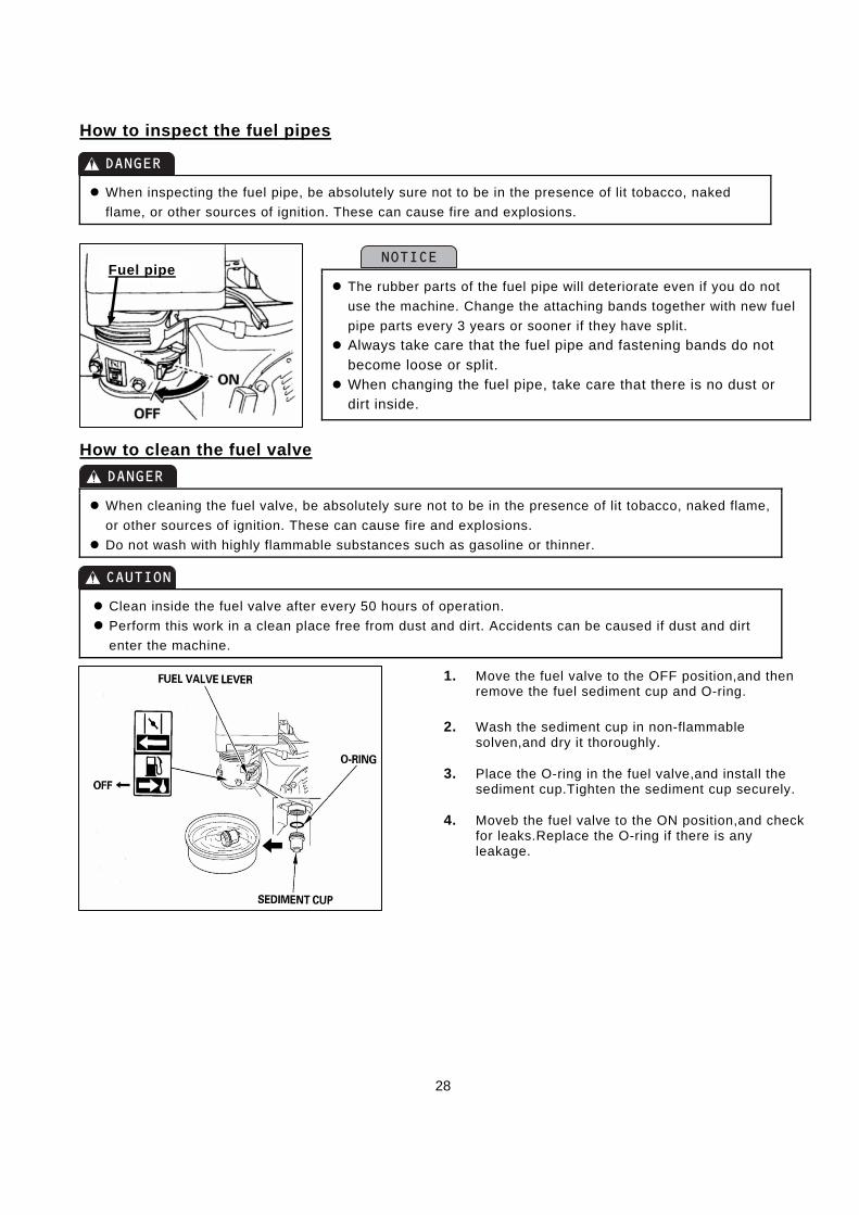
How to inspect the fuel pipes
When inspecting the fuel pipe, be absolutely sure not to be in the presence of lit tobacco, naked
flame, or other sources of ignition. These can cause fire and explosions.
How to clean the fuel valve
When cleaning the fuel valve, be absolutely sure not to be in the presence of lit tobacco, naked flame,
or other sources of ignition. These can cause fire and explosions.
Do not wash with highly flammable substances such as gasoline or thinner.
Clean inside the fuel valve after every 50 hours of operation.
Perform this work in a clean place free from dust and dirt. Accidents can be caused if dust and dirt
enter the machine.
1. Move the fuel valve to the OFF position,and then remove the fuel sediment cup and O-ring.
2. Wash the sediment cup in non-flammable
solven,and dry it thoroughly.
3. Place the O-ring in the fuel valve,and install the sediment cup.Tighten the sediment cup securely.
4. Moveb the fuel valve to the ON position,and check
for leaks.Replace the O-ring if there is any leakage.
The rubber parts of the fuel pipe will deteriorate even if you do not
use the machine. Change the attaching bands together with new fuel
pipe parts every 3 years or sooner if they have split.
Always take care that the fuel pipe and fastening bands do not
become loose or split.
When changing the fuel pipe, take care that there is no dust or dirt inside.
DANGER
CAUTION
NOTICEFuel pipe
DANGER

29
How to inspect and adjust the spark plug
1. Remove the spark plug with a plug wrench and clean away any carbon deposits on the electrode (A) with a wire brush and wipe away any moisture if present.
2. Replace the spark plug with a new one if the ceramic part has cracked or the electrode have suffered extensive wear and tear.
3. P 4. lease adjust the spark plug electrode clearance (B) to 0.7-0.8mm (0.028-0.031in).
When attaching a spark plug onto the engine, screw by hand at first before tightening with a plug
wrench. If you start by using a plug wrench to screw in the spark plug, there is a danger of cross-
threading it. (Refer to spark plug standards, page 33.)
NOTICE

30
How to adjust each wire and belt
When adjusting each type of wire, place the machine on flat, open ground with the engine switched off and making sure you take sufficient safety precautions.
■Adjusting the drive clutch wire
Refer to diagram 1 and use the adjust nut to loosen or tighten the
drive clutch wire. - If you engage the clutch and place a load on the machine but the
belt slips and the machine stops, you need to move the adjust nut
in the direction of (B).
- If you release the drive clutch lever but the belt still keeps rotating and the machine is difficult to switch off, move the adjust nut in
the direction of (A). After adjusting, fix the adjust nut by
tightening the lock nut.
Put the drive clutch lever in the [OFF] position, leaving 3-5mm of room for it to maneuver.
■Adjusting the blade clutch wire
Refer to diagram 2 and use the adjust nut to tighten or loosen the
blade clutch wire.
After adjusting, fix the adjust nut by tightening the lock nut. - If you engage the blade clutch lever and place a load on the
machine but the blades stop rotating, you move the adjust nut in
the direction of (B). - If you release the blade clutch lever but the blades fail to
stop, move the adjust nut in the direction of (A).
The blade brake is moved by operating the blade clutch lever. After adjusting the blade clutch wire, please check the effect on the blade brake. The machine is working well if the blades stop rotating around 3 seconds after releasing the blade clutch lever.
Put the blade clutch lever in the [OFF] position, leaving 3-5mm of room for it to maneuver.
WARNING
NOTICE
CAUTION
Diagram 2
Lock nut Adjust nut
NOTICE
Diagram 1
Lock nut Adjust nut

31
■Adjusting the side clutch wire
Refer to diagram 3 and use the adjust nut to tighten or loosen the side clutch wire.
- If you return the side clutch lever but drive will not engage, move
the adjust nut in the direction of (A). - If you grip the side clutch lever but drive will not stop, move the
adjust nut in the direction of (B). After adjusting, fix the adjust nut by tightening the lock nut.
■Adjusting the handlebar up/down wire
Refer to diagram 4 and use the adjust nut to tighten or loosen the
handlebar up/down wire. - If you move the lever but the handlebars do not move up or down,
move the adjust nut in the direction of (B). - If you do not move the lever but the handlebars move up or down
when a load is placed on the machine, move the adjust nut in the
direction of (A). After adjusting, fix the adjust nut by tightening the lock nut.
■Adjusting the parking brake wire
If you neglect to adjust the parking brake, it could drag while you are driving the machine, or the brake could fail while you are on a slope, causing the machine to run out of control.
Refer to diagram 5 and use the adjust nut to tighten or loosen the
parking brake if you detect any abnormalities.
- If you release the drive clutch lever but the parking brake is ineffective, move the adjust nut in the direction of (B).
- If the parking brake is on while driving (parking brake can not be
released), move the adjust nut in the direction of (A). After adjusting, fix the adjust nut by tightening the lock nut.
■Adjusting the blade belt
Make sure that the blade belt is always in a state of tension.
Refer to diagram 6 and follow the below points to adjust the belt
tension when you replace the belt or if the belt slips when a load is
placed on the machine. 1. Push the center of the belt with your finger and tighten the adjust
nut so that there is about 3-5mm of clearance.
2. After adjusting, fix in place by tightening the lock nut.
図 4
Diagram 4
Diagram 3
CAUTION
Diagram 6
3-5mm
Lock
nut
Tension pulley
Adjust nut
Lock nut Adjust nut
Lock nut Adjust nut
図 4
Diagram 5
Lock nut Adjust nut

32
■Adjusting the drive/middle belt guard
If you replace the belt, refer the diagrams 7 and 8 for how to adjust the tension of the belt and belt guard.
Adjust the drive and blade clutch levers to the [ON] position.
Adjusting the belt tension
When you push the center of the belt with your finger (roughly until the
tension pulley moves), the drive belt should bend around 12-14mm and the middle belt should bend around 10-12mm. At first, adjust belt
tension by tightening or loosening the adjust nuts of the wires. If the
belt still needs further adjustment, you can also adjust its tension by pushing the engine forward or backward.
■Adjusting the belt guide
To adjust the position of the belt guide, adjust the middle belt.
Adjust the belt so that when it is under tension, the clearance on the
upper side is around 3mm and the clearance on the lower side is
around 4mm.
Be sure to securely reattach any removed covers back to their original positions after removing to perform adjustments.
After adjusting, be sure to check the [ON] / [OFF] movement of each clutch lever. Please readjust new belts as they will stretch a little after 2-3 hours of use. Belts are consumable parts. Replace with new parts if you notice any abnormalities. Adjust
after the first 20 hours and then every 100 hours thereafter. For belt size, refer to page 33.
Precautions in cold climate
In winter, be sure to remove any mud and debris from the machine and park it on a concrete or other hard surface after using it. Material stuck to the machine can freeze and cause damage.
If you are unable to drive the machine due to freezing, do not force the machine to move but pour hot water on the affected frozen parts and wait for the ice to melt. Be especially careful as you will bear responsibility for damage caused by pushing the machine beyond its limits.
CAUTION
CAUTION
Diagram 7
Drive 12-14mm
Clearance 10-12mm
3mm
4mm
Diagram 8

33
Blade Inspection and Replacement
In order to work as safely as possible, perform an inspection of the blades before you start.
When inspecting or replacing the blades, always be sure to switch off the engine as there is a danger of
injury.
When having the blades replaced or repaired, always have any such work performed by a person with
adequate tools and experience.
To avoid injury, wear safety gloves when performing inspection or replacement and wrap the tips of the
blades in cloth.
When replacing the blades, be sure to also replace the nuts and bolts which tighten the blades. This prevents accidents caused by wear and tear on the nuts and bolts. Never use nuts and bolts that are
not recommended for this specified purpose.
Before using the machine, check for evidence of recent blade contact with curb stones or tree roots, blade bending, damage, and wear and tear.
If you neglect blade wear and tear, breakage, bending, and other damage, and continue to operate machine, blades could snap and fly out, possibly severely injuring the operator or bystanders. Engine
fires can also be caused by abnormal vibrations.
When running the blades at high speed, vibration can be caused even if only 1 blade is missing or
broken. The machine cannot be operated safely in a continuous state of vibration, it is very dangerous.
Vibration can also cause damage such as cracks and breaks to each part of the machine.
How to inspect and replace the blades
1. Stop the engine and remove the spark plug cap to be
doubly sure. (Refer to page 16 for how to stop the
engine)
2. Use the cutting height adjustment lever to raise the blades to their highest position.
3. Raise the front flappers to inspect the blades for
breakage, bending, and wear and tear. 4. Remove the front flappers when replacing any abnormal
blades. To remove the front flappers, first remove the front flappers set bolt. After finishing replacement work,
be sure to return the front flappers securely in ts original
position.
More frequent inspection the blades is necessary if using the machine on areas including dry earth and sand
which cause faster wear and tear of the blades.
We recommend purchasing spare blades in advance and keeping them close at hand.
Use only the manufacturer’s blades and blade attaching bolts. Shaking of the blade drum is also a cause of vibration. In this case, the blade drum ASSY has to be
replaced as the blade drum can not be repaired. Replace blades according to damage suffered. Please change all blades at the same time except in the
case that only 1 or 2 are damaged. Do not use old and new blades together as this will result in
abnormal vibrations.
WARNING
NOTICE
Front Flappers set bolt
Front Flappers

34
Regarding Long-Term Storage
If you do not use the machine for more than 30 days, please carry out the following procedures for maintenance.
If the machine is not stored properly, there is a danger of fuel spoilage, the machine failing to start, or trouble
running the machine.
Please work on the machine in a place that is well ventilated. Fuel gas can fill a room and cause accidents.
Before storing the machine, switch off the engine and remove the spark plug cord.
Store the machine on a flat surface in a room that is cool, well ventilated and protected from the outdoor
elements.
When removing fuel, do not work anywhere near lit cigarettes, naked flame or any sources of ignition. There
is a danger of the machine catching fire.
Before removing fuel, wait for the engine and muffler to cool down sufficiently before you touch them. There
is a danger of burns. Take care to handle removed fuel responsibly
If you neglect to clean accumulations of weeds and dust from inside the machine, blockages can cause
the engine to overheat, burn or catch fire the next time you use the machine.
1. Loosen the drain bolt, drain the fuel from inside the carburetor. Remove fuel from fuel valve and fuel tank. Choose a dry place to
store the machine.
2. Use a cloth to wipe away any traces of oil from the outside of the
engine and machine body.
3. Replace engine oil. 〈Refer to page 23 for how to replace the engine oil.〉
4. Be sure to clean each part sufficiently. In particular, clean out accumulations of weeds and dust from such
places as the recoil starter, air filter, carburetor, and inside the belt
cover. Clean any rust from exposed parts and apply anti-corrosion
paint.
5. Refuel and relubricate all parts that need fuel, oil, or grease.
6. Engage the parking brake and store the machine on a flat surface in a room that is cool, well ventilated
and protected from the outdoor elements.
7. Put a cover over the machine to keep dust out.
It is relatively easy to wash out waste weeds, etc, from inside the blade cover if you use a pressurized water hose and clean the waste out before it dries. At this time, make sure that water only contacts the
cover, not the engine’s electrics, carburetor, air filter, and muffler exhaust opening. This can damage
the engine’s ability to start.
During storage, check the tire pressure periodically and add air as necessary.
WARNING
NOTICE
Carburetor
Drain plug
Fuel valve

35
Specifications (Reference values)
Name Hammer Knife Rotor
Model AHR662
Length x Width x Front height (mm) 1900 x 800 x 980
Cutting width (mm) 650
Weight (kg) 160
Cutting height (mm) 50-100
Blade (no.) Free blade x38
Belt
Drive SA47 x 1
Middle SB63 x 1
Blade SB39 x 1
Drive tire size 16×7.00-8(φ400)
Handlebars Square handlebars (one-touch adjustable, 3 positions)
Brakes Equipped with parking brake and blade brake
Speed
(km/h)
Forward 0.95、1.99、3.5
Reverse 0.95
En
gin
e
Name Honda
Model GX270U-SAX4
Exhaust vol.(cc) 270
Engine Oil vol. 1.1L (1.2 US pt)
Max. output 6kw (8.2ps) / 3,600 rpm
Start up method Recoil starter
Spark plug BPR6ES(NGK),W20EPR-U(DENSO)
Fuel Tank vol. 5.3L (1.40 US gal)
*Changes may be made to improve the specification without prior notice.

36
Included Parts and Tools
No. Part name Standard/size Quantity Note
1. Instruction manual 1
2. Quality warranty 1
3. Engine tool Attached to engine 1
4. Double-ended wrench 10×12 1
5. “ 14×17 1
6. Goggles Anti-fog type 1 Protective equipment
Consumable Parts
No. Part name Part no. Quantity Note
1. Free blade 0304-70300 38
2. Attaching bolt set 0304-70000 19
3. Drive belt 89-6122-004700 1 SA47
4. Middle belt 89-6123-006300 1 SB63
5. Blade belt 89-6123-003901 1 SB39
6. Throttle wire 0226-70300 1
7. Drive/Blade wire 0304-70400 1 of each
8. Brake wire 0304-70600 1
9. Side clutch wire 0304-70500 2
10. Handlebar up/down wire 83-1110-965-00 1
11. Parking brake show 85-1711-316-00 1
12. Blade brake 80-1417-371-00 1
13. Caution mark (big) 0220-70700 1
14. Blade cover danger mark A 0220-70800 2
15. Belt cover warning mark 0220-71100 2
16. Engine danger mark 0304-71100 1
17. Blade cover danger mark 0304-71200 2
18. Wheel axle pin 0282-31300 2

37
Periodic Voluntary Inspection Table Neglecting inspection and maintenance is a cause of accidents and damage. Perform inspection referring to
[Periodic voluntary inspection table] in order to always keep the machine functioning correctly.
Perform annual inspection once a year and monthly inspection once a month, and starting checks every time you
use the machine.
item
Inspection Content
Inspection freq.
d m y
En
gin
e
Engine (Main body)
Condition at startup, abnormal noise. Machine starts up easily.
Power and acceleration state Power increases gradually and smoothly.
State of exhaust and gas leakage Exhaust color, smell, and sound are normal.
Air filter damage, loosening, cleanliness
No damage, loosening, or noticeably dirty.
Loosening of the attachment of cylinder head and manifolds
Gas leak, cracking, noticeable corrosion. *(Tightened to the correct torque, not loose)
*Valve tappet clearance Clearance looks straight. *Compressive pressure Compressive pressure looks straight.
Engine base cracking or deformity, loosening of nuts and bolts
The engine base is not cracked or deformed and the nuts and bolts are not loose.
Engine Lubrication
Quantity, cleanliness. Oil quantity is suitable, not dirty or mixed with any water or metals.
Oil leakage Oil seal and gasket are not leaking oil.
Engine Fuel
Fuel leakage Fuel is not leaking。
Fuel filter blockage Not noticeably dirty, deformed, or clogged.
Fuel quantity/quality There is fuel in the engine and it is of good quality.
Engine Electrics
Loosening. damage to electrical wires connections
Harness connections are suitable, not loose or damaged.
Engine Purity
Dirtying of air filter element Air filter element is not dirty.
Element breakage Element is not torn or worn out.
Engine Cooling
Weeds etc clogged in the recoil cover Recoil cover is not clogged with weeds.
Accumulation of weeds in the muffler There is no accumulation of weeds around the muffler.
Tra
nsm
ission
Belt Loosening There is suitable tension on the belt.
Damage, cleanliness Cracked, damaged, noticeably dirty.
Trans mission
Abnormal noise, strange
heat/movement
There are no abnormalities, strange noises or heat, when running the machine.
Oil quantity, cleanliness There is a suitable quantity of oil and it is not dirty.
Oil leakage Oil seal, packing parts are not leaking oil.

38
item
Inspection Content
Inspection freq.
d m y
Bo
dy
Body Cracking or deformity, mounting nuts and bolts are loose or have fallen off
Frame is not cracked or deformed. Nuts and bolts have not fallen off.
Cover Cracking, deformity, corrosion No cracking, deformity, corrosion.
Levers /Wires Damage, loosening, rattling of levers and wires, loss of split pins
When moving or loading, there is noticeable damage, loosening, rattling, or something has fallen off.
Drive
Tires (Wheels)
Air pressure and tread depth Standard values are observed.
Cracking, damage, wear and tear No cracks, damage or wear and tear.
Metal, stones, etc, stuck in the tires There is no debris in the tires.
Loose or missing nuts and bolts Nuts and bolts are not loose or missing.
Rattling, strange noise Mounted parts do not rattle or are missing.
Labels Damage Warning labels and nameplate are attached and not damaged.
*For new labels, please consult with your local retailer. Charges apply.

39
Self Diagnosis Table
If any of the following effects occur, refer to the instruction manual and take the appropriate action.
Effect Cause Treatment
Cut weeds are not released properly.
Weeds are wet. Operate machine when weeds are dry.
Weeds are too long. Raise the cutting height and cut twice.
Cutting height is too low. Raise the cutting height.
Engine power is too low. Increase engine power.
You are moving the machine too fast. Reduce your own speed of operation.
Weed deposits come out of the machine.
You are moving the machine too fast. Reduce your own speed of operation.
Engine power is too low. Increase engine power.
Blade is worn out, broken. Replace with a new blade.
Weeds have accumulated inside the blade
cover. Clean inside the blade cover.
Weeds are too long. Raise the cutting height and cut twice.
Machine starts cutting into the ground.
Cutting height is too low. Raise the cutting height.
Swing speed is too fast. Reduce swing speed.
Undulating ground. Change the direction of your cut.
Bumpy ground Raise the cutting height.
Bending of the blade. Replace with a new blade.
Slipping blade.
Belt tension is too low. Adjust belt tension.
Debris is clogged inside the blade cover. Clean inside the blade cover.
Weed accumulation in the pulley. Clean the pulley.
Belt wear and tear. Replace with a new belt.
Machine does not change gear.
Gear position is misaligned. Adjust gear rod.
Mission is in poor condition. Repair mission.
Big vibration.
Blades are poorly balanced. Readjust all blades
Blades are damaged Replace with new blades, or repair.
Accumulation of weeds inside the blade neck guard. Damage.
Clean or replace the blade neck guard.
Blade axle is bent Replace blade axle.
Belt breakage Replace with a new belt.
Mixing of old and new blades. Do not mix old and new blades.
Cutting workload is too heavy.
Engine power is too low. Increase engine power.
You are moving the machine too fast. Reduce you own speed of operation.
Weeds have accumulated or are wrapped around the blade axle.
Clean the blades.
Weeds are too long. Raise the cutting height and cut twice.
Cutting height is too low. Raise the cutting height.
Tires are slipping. Ground is too soft. Stop working until ground is dry.
Fuel cap springs off while operating the machine.
Too much mission oil has been put in. (internal pressure increase)
See that oil level is straight.
If you do not understand any of these points, please consult with the retailer where you purchased this machine.

40
Engine Defects and How to Manage Them
If the engine is defective, perform diagnosis by referring to the following table and then taking the appropriate
action.
Effect Cause Treatment
You have trouble starting the machine, or the machine will not start at all.
Safety switch is not in the [start up] position. Put the safety switch to the [start up] position.
Choke lever has not been pulled out. When cooling the engine, put the choke bar in the position.
Fuel is not flowing properly.
Inspect fuel tank, remove impure deposits or water. Remove the fuel valve strainer and clean out any sediment deposited inside the cap together with any other attached dirt.
There is air or water mixed in the fuel delivery system.
Remove foreign object, inspect fastening bands, replace damaged parts with new ones.
In cold weather, oil becomes thick, and so the rotation of the engine heavy.
Use the correct oil depending on the outside temperature.
Ignition coil or unit is defective. *Replace the ignition coil or unit.
Defective spark plug. Inspect the gap between spark plug electrodes and adjust. Replace with new spark plug.
Output shortage
Fuel shortage. Refuel the machine.
Clogged air filter. Clean the element.
Poor quality fuel. Replace with good quality fuel.
Choke has not been fully opened. Return the choke bar completely. Put it in the position.
Cooling system is clogged. Clean around the recoil starter.
The machine stops suddenly.
Fuel shortage. Refuel the machine.
Fuel valve is closed. Open the fuel valve.
Exhaust gas is abnormally black
Poor quality fuel. Replace with good quality fuel.
Overfilled with engine oil. See that oil level is straight.
Muffler emits black smoke and power output falls.
Air filter element is clogged. Clean the element.
Choke has not been fully opened. Return the choke bar completely. Put it in the position.
Muffler emits gray smoke.
Overfilled with engine oil. Check that oil level is straight.
Cylinder or piston ring is worn out *Replace the ring.
Engine power is not stable (does not increase).
Choke has not been fully opened. Return the choke bar completely. Put it in the position
Poor quality fuel. Replace with good quality fuel.
Momentary stall. Defective ignition coil. *Replace the ignition coil.
Fuel filter is clogged. Clean the fuel filter.
Exhaust has an irritating smell.
Poor quality fuel. Replace with good quality fuel.
*For new labels, please consult with your local retailer. Charges apply.
If you do not understand any of these points, please consult with the retailer where you purchased this machine.

OREC HRC662 - © SAT 11/2007 41
CONFORMITY CERTIFICATE
I undersigned : OREC CO LTD 548-22 HIYOSHI HIROKAWA-MACHI YAME-GUN JAPON Certify that the mower : 1. Class : ……..................................internal combustion engine.................................................................... 2. Mark : ...................................................................OREC............................................................................ 3. Type : ...................................................................AHR662......................................................................... 4. Serial Identification (to be completed) : ................................................................................................... 5. Engine : - Manufacturer : ...............................………………. HONDA......……............ …………………….…………… - Model : ..................................................................GX270..................................................................... - Speed during tests : ..................................................... 2900 +/- 20.....................................................(rpm) is complying with directive 2000/14 EC specifications. Granted acoustic power level : .................................................97…......................................................dB(A) Granted acoustic pressure level : ............................................87...............….……………………….….dB(A) - Cutting device : ...........................................................rotative.flails............................................................... - Cutting width : ...........................................................................650.........................................................mm - Cutting width speed : ......................................... 2800+/-20………...................................................... (rpm) made at .......Fukuoka.........…....... Date : october 20-2010....................
Signed : Haruhiko Imamura Function : Managing director
CONFORMITY DECLARATION I undersigned : OREC CO LTD 548-22 HIYOSHI HIROKAWA-MACHI YAME-GUN JAPON Certify that the mower : 2. Mark : ................................................................OREC................................................................................... 3. Type : ................................................................AHR662............................................................................. 4. Serial number (to be completed): ................................................................................................................... Distributed by : ……………………………………………………………………….……………………...…..………. ……………………………………………………………………………………..……………….……………………… complies with directive 2006/42, 2000/14 EC and EN 12733. made at......Fukuoka....…........Date : ... october 20-2010
Signed : Haruhiko Imamura Function : Managing director
MEASUREMENT OF VIBRATIONS Mark : OREC Machine : grassland mower Model : AHR662 Engine : HONDA GX270 Speed during test : 3600+/-20 rpm
ACCELEROMETER POSITION Awp 100 mm of the end of handlebar (left side) 5,79 m/s²
100 mm of the end of handlebar (right side) 5,77 m/s²
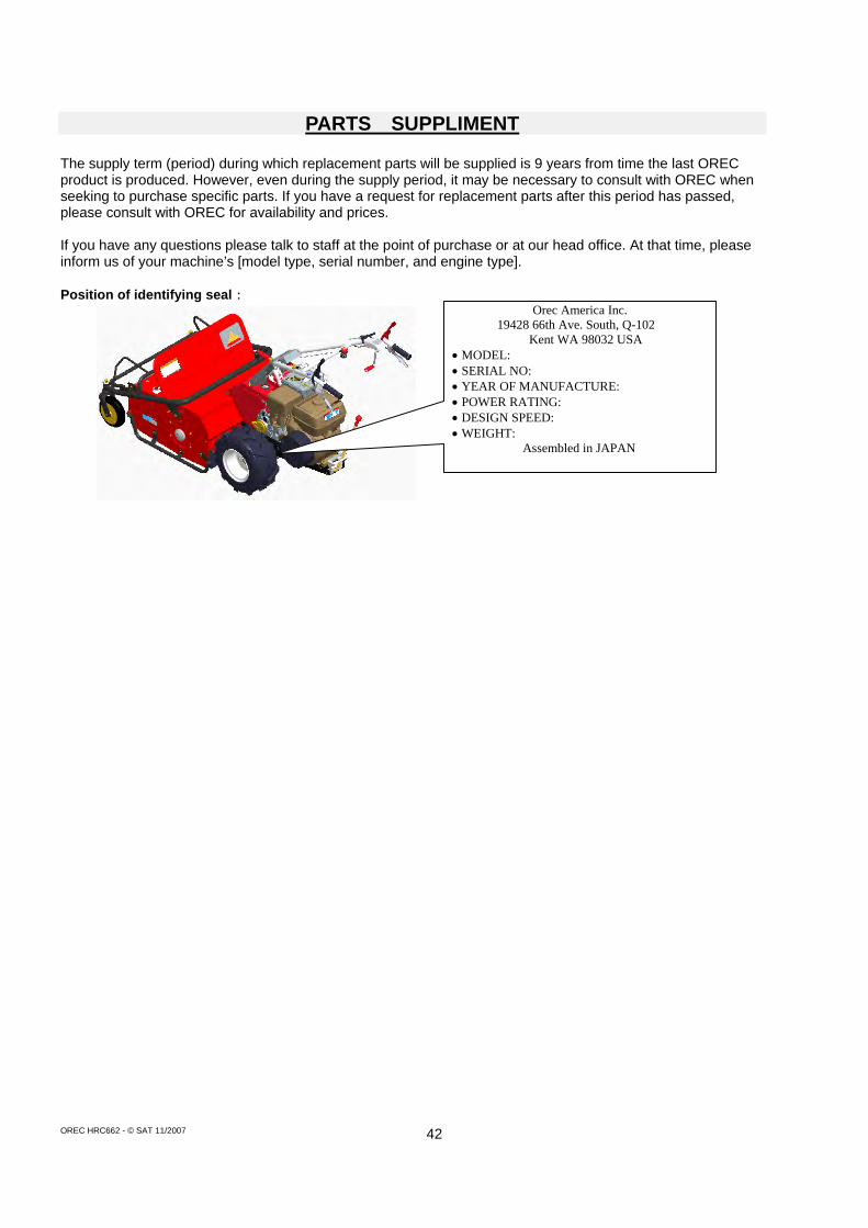
OREC HRC662 - © SAT 11/2007 42
PARTS SUPPLIMENT The supply term (period) during which replacement parts will be supplied is 9 years from time the last OREC product is produced. However, even during the supply period, it may be necessary to consult with OREC when seeking to purchase specific parts. If you have a request for replacement parts after this period has passed, please consult with OREC for availability and prices. If you have any questions please talk to staff at the point of purchase or at our head office. At that time, please inform us of your machine’s [model type, serial number, and engine type]. Position of identifying seal:
Orec America Inc. 19428 66th Ave. South, Q-102
Kent WA 98032 USA MODEL: SERIAL NO: YEAR OF MANUFACTURE: POWER RATING: DESIGN SPEED: WEIGHT:
Assembled in JAPAN

OREC HRC662 - © SAT 11/2007 43
LIMITED WARRANTY Terms and Conditions • Orec America, Inc. provides a limited warranty of two (2) years for residential users, one (1) year for commercial users, and one (1) year for rental companies, of its products against defects in workmanship and materials when said products are put to ordinary and normal use. The terms and conditions of the limited warranty are as set forth herein. • The second year of the residential warranty shall cover only parts and NOT service • Crawlers are guaranteed for one hundred eighty (180) days after initial purchase. This warranty covers defects in materials or workmanship only, and does not include damage to crawlers from normal use and other external factors. • The warranty shall commence from the date of purchase. This warranty is available only to the original purchaser, and is not transferable. • OREC reserves the right to inspect covered machines and parts in order to determine the validity of warranty claims • For the purposes of the above warranties “ordinary and normal use” does not include misuse, accidents, or damage due to inadequate maintenance. • Under this warranty, the responsibility of Orec America is limited to replacement or repair of defective parts at Orec America, or at an authorized Orec dealer. • Routine maintenance and adjustments, as defined by the manufacturer’s owners’ manuals, are the responsibility of the user and are not covered by the warranty. •Degradation or deterioration of the product due to everyday use are excluded from the warranty •Expendable components including but not limited to such as belts, blades, filters, spark plugs, bags, wheels hoses, cables, wires, brake pads and flappers, are excluded from the warranty. This warranty does NOT cover tire replacement or repair caused by punctures from outside objects, such as nails, thorns, stumps or glass. • During the warranty period, the warranty holder is responsible for equipment transportation charges, and transportation expenses needed to process the claim will not be reimbursed. • The following are excluded from the warranty: ・Repairs necessary due to inappropriate use or abuse including, but not limited to, damage
caused by towing objects or overspeeding the engine. ・Paint peeling or rust that occur through exposure to the elements or through everyday use
shall not be covered by the warranty. ・Repairs necessary because of operator negligence, including but not limited to, electrical and
mechanical damage caused by improper storage, failure to use the proper grade and amount of engine oil, failure to keep the mowing deck clear of flammable debris, or the failure to maintain the equipment according to the instructions contained in the owner’s manual.
・Repairs necessary because of accidents. ・Engine (fuel system) cleaning or repairs caused by fuel determined to be contaminated or
oxidized (stale). In general, fuel should be used within thirty (30) days of its purchase date. ・Claims made after expiration of the warranty. ・Claims that are NOT specifically covered by warranty.
• Repairs, maintenance and/or modifications performed by unauthorized persons or dealers, as well as the use of unauthorized parts or accessories will lead to the immediate forfeiture of the warranty • Under NO circumstances shall Orec America be liable for damages or expenses of any kind resulting from inappropriate use of its products. • Orec America shall NOT be responsible for incidental or consequential costs or damages resulting from defects in its machinery. Such excluded costs and damages may include : 1) Labor 2) Lost sales 3) Cost of replacement parts.

OREC HRC662 - © SAT 11/2007 44
• This warranty shall apply only to models sold within the United States and purchased from authorized dealers. Note: to request warranty service, please contact an authorized Orec dealer or refer to your owner’s manual for the proper procedure THIS WARRANTY GIVES YOU SPECIFIC LEGAL RIGHTS AND YOU MAY HAVE OTHER RIGHTS WHICH MAY VARY FROM STATE TO STATE. SOME STATES DO NOT ALLOWTHE EXCLUSION OR LIMITATION OF INCIDENTAL OR CONSEQUENTIAL DAMAGES, SO THE ABOVE LIMITATIONS MAY NOT APPLY TO YOU.
Warranty Registration Register your information within 30 days of purchase at http://www.orecamerica.com/warranty.htm
Warranty Claim Procedure Should this Orec product fail due to a defect in materials and/or workmanship, the owner should use the following procedure to make a warranty claim: 1) The owner must take the machine to the dealer from whom they purchased the machine or to an authorized Orec America dealer. 2) The owner must present the warranty registration sheet or the invoice or receipt received at time of purchase. 3) The warranty claim will be taken and verified by the Orec Dealer or distributor service manager and submitted to an Orec distributor. The dealer or distributors service manager will make a report and submit it to Orec America for consideration of Warranty. 4) Orec will research the claim and may request that parts be returned for further examination. Orec will report their decision to the distributor service manager or dealer from whom the claim was received. 5) In the event that OREC approves the claim, parts will be exchanged free of charge and repairs performed by the dealer. 6) The decision by the Quality/Service department to approve or reject a warranty is final and binding Note: to process a warranty claim, it is necessary to include the model name and serial number which are printed on the Orec Serial Plate


![WooDSHREDDER, HL-SERIES HL 2/7/10 - JW Industri · PDF fileExCLuSIvE RoToR AND KNIFE DESIgN [ 1-2 ] the knife and knife precision mounting arrangement ensure a long tool life, optimal](https://static.fdocuments.us/doc/165x107/5a87588c7f8b9a9f1b8db15c/woodshredder-hl-series-hl-2710-jw-industri-rotor-and-knife-design-1-2.jpg)