Self-Powered Dual-Mode Amenity Sensor Based on the …... · ACS Paragon Plus Environment ......
33
Subscriber access provided by AUSTRALIAN NATIONAL UNIV ACS Nano is published by the American Chemical Society. 1155 Sixteenth Street N.W., Washington, DC 20036 Published by American Chemical Society. Copyright © American Chemical Society. However, no copyright claim is made to original U.S. Government works, or works produced by employees of any Commonwealth realm Crown government in the course of their duties. Article Self-Powered Dual-Mode Amenity Sensor Based on the Water-Air Triboelectric Nanogenerator Hao Wang, Han Wu, Dihan Hasan, Tianyiyi He, Qiongfeng Shi, and Chengkuo Lee ACS Nano, Just Accepted Manuscript • DOI: 10.1021/acsnano.7b05213 • Publication Date (Web): 02 Oct 2017 Downloaded from http://pubs.acs.org on October 6, 2017 Just Accepted “Just Accepted” manuscripts have been peer-reviewed and accepted for publication. They are posted online prior to technical editing, formatting for publication and author proofing. The American Chemical Society provides “Just Accepted” as a free service to the research community to expedite the dissemination of scientific material as soon as possible after acceptance. “Just Accepted” manuscripts appear in full in PDF format accompanied by an HTML abstract. “Just Accepted” manuscripts have been fully peer reviewed, but should not be considered the official version of record. They are accessible to all readers and citable by the Digital Object Identifier (DOI®). “Just Accepted” is an optional service offered to authors. Therefore, the “Just Accepted” Web site may not include all articles that will be published in the journal. After a manuscript is technically edited and formatted, it will be removed from the “Just Accepted” Web site and published as an ASAP article. Note that technical editing may introduce minor changes to the manuscript text and/or graphics which could affect content, and all legal disclaimers and ethical guidelines that apply to the journal pertain. ACS cannot be held responsible for errors or consequences arising from the use of information contained in these “Just Accepted” manuscripts.
Transcript of Self-Powered Dual-Mode Amenity Sensor Based on the …... · ACS Paragon Plus Environment ......
Subscriber access provided by AUSTRALIAN NATIONAL UNIV
ACS Nano is published by the American Chemical Society. 1155 Sixteenth StreetN.W., Washington, DC 20036Published by American Chemical Society. Copyright © American Chemical Society.However, no copyright claim is made to original U.S. Government works, or worksproduced by employees of any Commonwealth realm Crown government in the courseof their duties.
Article
Self-Powered Dual-Mode Amenity Sensor Basedon the Water-Air Triboelectric Nanogenerator
Hao Wang, Han Wu, Dihan Hasan, Tianyiyi He, Qiongfeng Shi, and Chengkuo LeeACS Nano, Just Accepted Manuscript • DOI: 10.1021/acsnano.7b05213 • Publication Date (Web): 02 Oct 2017
Downloaded from http://pubs.acs.org on October 6, 2017
Just Accepted
“Just Accepted” manuscripts have been peer-reviewed and accepted for publication. They are postedonline prior to technical editing, formatting for publication and author proofing. The American ChemicalSociety provides “Just Accepted” as a free service to the research community to expedite thedissemination of scientific material as soon as possible after acceptance. “Just Accepted” manuscriptsappear in full in PDF format accompanied by an HTML abstract. “Just Accepted” manuscripts have beenfully peer reviewed, but should not be considered the official version of record. They are accessible to allreaders and citable by the Digital Object Identifier (DOI®). “Just Accepted” is an optional service offeredto authors. Therefore, the “Just Accepted” Web site may not include all articles that will be publishedin the journal. After a manuscript is technically edited and formatted, it will be removed from the “JustAccepted” Web site and published as an ASAP article. Note that technical editing may introduce minorchanges to the manuscript text and/or graphics which could affect content, and all legal disclaimersand ethical guidelines that apply to the journal pertain. ACS cannot be held responsible for errorsor consequences arising from the use of information contained in these “Just Accepted” manuscripts.
1
Self-Powered Dual-Mode Amenity Sensor Based on
the Water-Air Triboelectric Nanogenerator
Hao Wang, Han Wu, Dihan Hasan, Tianyiyi He, Qiongfeng Shi and Chengkuo Lee*
Hao Wang, Han Wu, Dihan Hasan, Tianyiyi He, Qiongfeng Shi and Chengkuo Lee
Department of Electrical and Computer Engineering, National University of Singapore, 4
Engineering Drive 3, Singapore 117583
Center for Intelligent Sensors and MEMS, National University of Singapore, 4 Engineering
Drive 3, Singapore 117576
NUS Suzhou Research Institute (NUSRI), Suzhou, Industrial Park, Suzhou, P. R. China 215123
Corresponding Author
*Chengkuo Lee
E2-03-29
Electrical and Computer Engineering, National University of Singapore, 4 Engineering Drive 3
Singapore, 117583
+65 6516-5865
KEYWORDS portable, CO2 sensing, humidity calibration, force free, charge-based
characterization
Page 1 of 32
ACS Paragon Plus Environment
ACS Nano
123456789101112131415161718192021222324252627282930313233343536373839404142434445464748495051525354555657585960
2
ABSTRACT
A water-air triboelectric nanogenerator (WATENG) is presented for CO2 sensing application.
During the operation of WATENG, two independent charge transfers can be used to characterize
the effect of force and humidity, respectively. Thus, the structure of WATENG provides a
capability to eliminate these two major interferences in a triboelectric self-powered sensor. With
the aid of the polyethylenimine (PEI) coating, WATENG can be used for CO2 sensing in both
static and dynamic conditions. In static condition with a stable CO2 concentration, the CO2
sensing is characterized with respect to different relative humidity, and the sensing range can be
up to 6000 ppm. In dynamic CO2 sensing of a pulse gas spray, due to the fast recovery of PEI
surface reaction, the sensing range of dynamic situation can be broadened to 30000 ppm. The
self-powered and portable feature of WATENG is preferable as a self-powered amenity sensor
for construction of internet of the things (IoT) sensor networks in the future.
Page 2 of 32
ACS Paragon Plus Environment
ACS Nano
123456789101112131415161718192021222324252627282930313233343536373839404142434445464748495051525354555657585960

3
Modern smart buildings provide amenities to users with the aid of advanced demand-controlled
Heating Ventilation Air Conditioning (HVAC) system,1 where it requires advanced sensor
networks to control the parameters such as temperature, humidity and CO2 concentration. By
leveraging the MEMS technology, a few amenity sensors of minimized dimension are developed
to fit requirements of the sensor networks.2-7
However, one of the essential issues cannot be
bypassed is the power consumption of present commercial amenity sensors. Taking the CO2
monitor, the main indicator of indoor air quality (IAQ), as an example, the information of air
flow at different locations in a large indoor space, e.g. office floor, ballroom, auditorium and
lobby, etc., needs to be collected in real-time manner such that the individually-controlled
dampers in this large indoor space can separately regular the distribution of air-flow. For the
construction of large-scale sensor networks and internet of the things (IoT) sensor networks used
in smart building in the future, the sensor nodes in the system shall have the capability of
operating independently, sustainably and maintenance-free. Otherwise, because massive sensor
nodes are distributed within the entire area, periodic replacement of batteries in sensor nodes is a
labor intensive task and will create a significant amount of waste materials from batteries where
they are environmentally unfriendly and potentially hazardous to human health.8 Therefore, self-
powered sensor nodes is crucial for enabling a sensor network without using batteries.9-10
In the last decade, triboelectric nanogenerators (TENGs) show the great potential for mechanical
energy harvesters and self-powered sensors.11-19
The versatile nature of TENGs enables the
capability of sensing all parameters that are relevant to the factors affecting the performance such
as force, frequency and surface charge density. Recently, various types of triboelectric-based
sensors have been investigated such as the pressure sensor,20-25
vibration sensor,26-29
motion
sensor,30-32
liquid sensor 33-34
and chemical/environmental sensor.35-40
However, the versatile
Page 3 of 32
ACS Paragon Plus Environment
ACS Nano
123456789101112131415161718192021222324252627282930313233343536373839404142434445464748495051525354555657585960

4
nature of the triboelectric sensor also means that more interference will be introduced for the
application of sensing a specific parameter. One critical issue reported in usage of the
triboelectric sensor is the interference of humidity. Water vapor in air will affect the generation
of electrostatic charge, which is the key factor for contact electrification in triboelectric sensors.
The previous study confirms that the humidity fluctuation within a small range can induce a
large variation of the triboelectric output.41-43
Therefore, a proper calibration or even elimination
of humidity effect is necessary to enhance the sensing accuracy of triboelectric based sensor.
So far, several kinds of triboelectric chemical sensors have been investigated, such as Hg2+
ion
sensing 35
and catechin sensing,36
however, gas sensing is still a rarely touched field. A
preliminary study reports a stacked corrugated-core sandwich-structured TENG for H2 sensing.40
Although the detailed sensing mechanism still remains unknown and the result shows no sensing
selectivity to other gas species, it reveals gas sensing feasibility by triboelectric mechanism. In
this study, a polyethylenimine (PEI) layer was used as the CO2 selective sensing material
incorporated in TENG gas sensor. Hence, it becomes possible to develop a TENG gas sensor
with high sensing selectivity by having a special functional coating on top of the triboelectric
layer, where only a specific gas molecule can alter the surface property of that functional
material. Compared with current CO2 sensors,44-48
PEI can avoid the issues of cross-sensitivity,
long response time, poor reversibility and poor sensitivity which are mainly introduced by
imperfect sensing material properties.46-48
In the previous study, only the infrared investigation of
CO2 bulk absorption in the PEI layer was conducted for measuring the CO2 concentration.44-45
By investigating the change of the surface charge of PEI with CO2 absorption, a simple
triboelectrification process can replace the desk-top FTIR equipment for CO2 detection.
Page 4 of 32
ACS Paragon Plus Environment
ACS Nano
123456789101112131415161718192021222324252627282930313233343536373839404142434445464748495051525354555657585960
5
Here we propose a water-air triboelectric nanogenerator (WATENG) as a portable CO2 sensing
device. Meanwhile, the effect of humidity for CO2 sensing using PEI is calibrated. This is a
preliminary study that investigates how water molecules affect surface charge density so as to
enable self-generated triboelectric-based gas detection output charge.
Result and Discussion
WATENG Mechanism analysis and output characterization
Figure 1(a) shows a device configuration in the water-air triboelectric nanogenerator
(WATENG) for CO2 detection. This WATENG is comprised of a top air layer and a bottom
wetted sponge layer that is separated via a suspended PDMS thin film at the center. The contact
electrification between the top electrode and the upper surface of PDMS have a constant contact
area with a mutative humidity of the ambient environment. For the contact electrification
between the lower surface of PDMS and wetted sponge, this contact area is a function of applied
force where the humidity is kept at maximum and stable. Thus, during the operation, there will
be two independent charge transfer mechanisms: one is not affected by force, and another is not
affected by humidity. Hence, humidity and force can be characterized independently. In previous
investigation of triboelectric based sensors, a force control system is required for a stable
operation force to induce contact and separation.20-40
This force control system makes the entire
sensing system not portable. Therefore, TENGs can generate a stable output with varied force or
even directly measure the force, which is essential for developing portable self-powered
chemical sensors operated manually.
The CO2 sensing concept is shown in Figure 1(b). The PEI coating on the top electrode can
absorb CO2 and further change the electronegativity of its surface. Hence, the change of the
Page 5 of 32
ACS Paragon Plus Environment
ACS Nano
123456789101112131415161718192021222324252627282930313233343536373839404142434445464748495051525354555657585960
6
triboelectric output can be used to measure the CO2 concentration. For most cases, the change in
CO2 concentration is usually accompanied by a change of relative humidity (RH), e.g., during
exhalation. The effect of gaseous water in CO2 sensing is characterized in this study.
The detailed WATENG structure is shown in Figure 1(a). The entire device includes four layers.
The top and bottom ITO/PET electrodes act as the electrode pair of the device. The PEI layer,
which is a type of macromolecule for CO2 adsorbents, was dip-coated onto the top ITO/PET
electrode. A sponge is located at the center of the bottom ITO/PET electrode. During the
operation, the sponge is wetted with water, then, the water can be squeezed out. This this
function plays an important role for force sensing and output enhancement. The PDMS thin film,
which is located between the sponge and the top ITO/PET electrode, is fixed and stretched by a
frame to provide contact electrification between the two top electrodes and triboelectric charge
due to water being squeezed out from the sponge. A detailed fabrication process, optical and
SEM images of the WATENG can be found in supplementary S1.
Working mechanism of WATENG with PEI for Gas Sensing
The working mechanism is illustrated in Figure 2(a). The entire operation will induce a charge
flow cycle, as show in Figure 2(c). After the first cycle of operation, the suspended PDMS thin
film obtains negative electrostatic charges on both the upper surface, which is , and the lower
surface, which is , as shown in Figure 2(a-i). In this step, the top ITO/PET electrode is
separated from the PDMS thin film. Then, the ITO/PET electrode is pressed to produce a contact
with the PDMS thin film, as shown in Figure 2(a-ii). Due to the contact between ITO and PDMS
surface, the negative electrostatic charges on both sides of the PDMS thin film will be balanced
by the positive charge on the ITO/PET electrode, inducing a charge flow, which is + , from
Page 6 of 32
ACS Paragon Plus Environment
ACS Nano
123456789101112131415161718192021222324252627282930313233343536373839404142434445464748495051525354555657585960

7
the bottom ITO/PET electrode to the top ITO/PET electrode, which is indicated as in Figure
2(c). Then, we further press the top electrode to deform the suspended PDMS thin film and
compress the wetted sponge, as shown in Figure 2(a-iii). In this step, the water within the wetted
sponge will be squeezed out from the sponge and contact the lower surface of the PDMS thin
film. Hence, the negative electrostatic charge on the lower surface of the PDMS thin film, ,
which is initially balanced by the positive chare on the top electrode, will be coupled by positive
ions in water, which will form a so-called electric double layer. During this step, a charge flow
from the top electrode to the bottom electrode will be induced, indicated as in Figure 2(c).
Then, the top electrode is lift up to make the sponge absorb all of the water back, as shown in
Figure 2(a-iv). Again, without the electric double layer being formed by the contact between
water and lower surface of PDMS, the negative electrostatic charge on the lower surface of the
PDMS thin film will be balanced by the positive charge on the top electrode, which induces a
charge flow from the bottom electrode to the top electrode. Due to the sticky surface of
PDMS, PDMS can be lifted up together with the top electrode to a certain height before the
complete separation occurs, as shown in Figure 2(a-iv). In this step, the distance between the
bottom electrode and PDMS thin film is increasing, which will further lower the electrostatic
induction between them. Thus, a very small charge flow, , from the bottom electrode to the top
electrode will occur. During the entire lifting up process, a charge flow, indicated as , which is
comprised of and in Figure 2(c), will occur. If the top electrode is further lifted up, PDMS
will completely separate from the top electrode, making the entire device recover to the initial
status as shown in Figure 2(a-i). The negative electrostatic charge on both sides of the PDMS
thin film will be balanced by the entire environment, and a charge flow of , which is comprised
Page 7 of 32
ACS Paragon Plus Environment
ACS Nano
123456789101112131415161718192021222324252627282930313233343536373839404142434445464748495051525354555657585960

8
of , and , from the top electrode to the bottom electrode will occur, as indicated in Figure
2(c).
As explained in the working mechanism, the charge transfer in the entire cycle is determined by
the negative electrostatic charge on both sides of the PDMS thin film. The total negative
electrostatic charge should be the sum of , and . Among them, refers to the change of
the electrostatic induction between the top and bottom electrodes during the lifting up process
and is negligible because it is much lower than and for most cases. Then, and can be
considered as the charges on the upper and lower surfaces of the PDMS thin film, respectively.
Analysis of output affected by force and relative humidity
The relative humidity (RH) and force are the two major factors that make the performance of
TENGs unstable. Although it has been reported that water molecules can help stabilize the
charge generated by contact electrification,41
a higher RH will deteriorate the performance of
TENGs in terms of charge 42
and voltage 43
characteristics. Force will affect the contact area,
which directly determines the amount of electrostatic charge that participates in electrostatic
induction. Here, we made a detailed study of how and are affected by RH and force. Figure
2(b) shows the total charge transferred, which is the sum of and at different force, relative
humidity and water volume inside the sponge. The higher volume of water inside the sponge will
have a larger contact area between water and PDMS when the sponge is squeezed with the same
force. When the force is lower than 1.5 N, the total charge for water volume of 1 ml and 1.75 ml
is the same. This means that almost no water was squeezed out from the sponge. When the force
is higher than 1.5 N, the charge curve of 1.75 ml is always higher than that of 1 ml because more
water was squeezed out of the sponge to induce a larger contact area between water and PDMS.
Page 8 of 32
ACS Paragon Plus Environment
ACS Nano
123456789101112131415161718192021222324252627282930313233343536373839404142434445464748495051525354555657585960
9
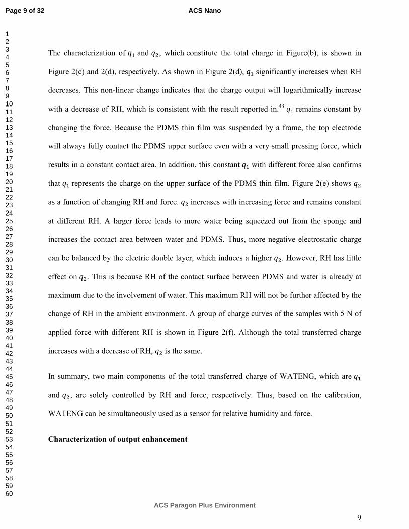
The characterization of and , which constitute the total charge in Figure(b), is shown in
Figure 2(c) and 2(d), respectively. As shown in Figure 2(d), significantly increases when RH
decreases. This non-linear change indicates that the charge output will logarithmically increase
with a decrease of RH, which is consistent with the result reported in.43
remains constant by
changing the force. Because the PDMS thin film was suspended by a frame, the top electrode
will always fully contact the PDMS upper surface even with a very small pressing force, which
results in a constant contact area. In addition, this constant with different force also confirms
that represents the charge on the upper surface of the PDMS thin film. Figure 2(e) shows
as a function of changing RH and force. increases with increasing force and remains constant
at different RH. A larger force leads to more water being squeezed out from the sponge and
increases the contact area between water and PDMS. Thus, more negative electrostatic charge
can be balanced by the electric double layer, which induces a higher . However, RH has little
effect on . This is because RH of the contact surface between PDMS and water is already at
maximum due to the involvement of water. This maximum RH will not be further affected by the
change of RH in the ambient environment. A group of charge curves of the samples with 5 N of
applied force with different RH is shown in Figure 2(f). Although the total transferred charge
increases with a decrease of RH, is the same.
In summary, two main components of the total transferred charge of WATENG, which are
and , are solely controlled by RH and force, respectively. Thus, based on the calibration,
WATENG can be simultaneously used as a sensor for relative humidity and force.
Characterization of output enhancement
Page 9 of 32
ACS Paragon Plus Environment
ACS Nano
123456789101112131415161718192021222324252627282930313233343536373839404142434445464748495051525354555657585960
10
Based on the explanation above, the electrostatic charge on both the upper and lower surfaces of
the PDMS thin film is used for generating the output. Apparently, compared with conventional
TENGs, in which only the upper surface of the dielectric layer is used for generating output, the
structure of the WATENG can generate more electrostatic charge, hence enhance the output.
Here we have a characterization of the output of 5 different structures of TENGs, including
conventional TENGs and WATENG. Considering that PTFE is a more popular material as the
dielectric to be used in TENGs for higher energy output,32, 49-50
here we used PTFE thin film
instead of PDMS thin film for all the five cases for the comparison of the output.
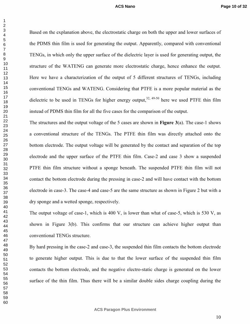
The structures and the output voltage of the 5 cases are shown in Figure 3(a). The case-1 shows
a conventional structure of the TENGs. The PTFE thin film was directly attached onto the
bottom electrode. The output voltage will be generated by the contact and separation of the top
electrode and the upper surface of the PTFE thin film. Case-2 and case 3 show a suspended
PTFE thin film structure without a sponge beneath. The suspended PTFE thin film will not
contact the bottom electrode during the pressing in case-2 and will have contact with the bottom
electrode in case-3. The case-4 and case-5 are the same structure as shown in Figure 2 but with a
dry sponge and a wetted sponge, respectively.
The output voltage of case-1, which is 400 V, is lower than what of case-5, which is 530 V, as
shown in Figure 3(b). This confirms that our structure can achieve higher output than
conventional TENGs structure.
By hard pressing in the case-2 and case-3, the suspended thin film contacts the bottom electrode
to generate higher output. This is due to that the lower surface of the suspended thin film
contacts the bottom electrode, and the negative electro-static charge is generated on the lower
surface of the thin film. Thus there will be a similar double sides charge coupling during the
Page 10 of 32
ACS Paragon Plus Environment
ACS Nano
123456789101112131415161718192021222324252627282930313233343536373839404142434445464748495051525354555657585960

11
pressing and hence enhance the output. However, because of the air gap, which leads to a large
inner impedance, the output voltage is much lower compared with case-5.
For case-4, since the sponge is dry, no water can be squeezed out of the sponge. The
electrification between the PTFE and sponge cannot be as efficient as either between the water
and PTFE or between the PTFE and ITO. Although there is negative charge generated upon the
lower surface of the PTFE thin film, the output voltage is still lower than case-3 and case 5.
We also characterize the output power and inner impedance for case-1 and case-5, as shown in
Figure 3(c), since these two give the best performance. As can be seen, the output voltage of
case-5 was always higher than case-1. The maximum output power for case-5 is 15.2 mW at 3.47
MΩ, while for case-1 is 9.55 mW at 9.4 MΩ. The WATENG structure of case-5 can achieve not
only higher optimum output power but also a lower matched load resistance.
In summary, the developed WATENG structure with a suspended thin film and wetted sponge
can enhance the performance compared with conventional TENG structure. In this research, we
did not optimize the material of the suspended thin film. Actually quite a lot of techniques,
including the surface treatment, surface coating and better material selection, are investigated to
enhance the output. The suspended thin film structure is compatible with all these material
optimizations for a better performance.
Static CO2 Sensing at different RH
To demonstrate the application of WATENG as a CO2 sensor, a layer of polyethylenimine (PEI)
was dip-coated onto the ITO/PET electrode. The PEI is the most commonly used macromolecule
for CO2 adsorbents because of its high amine content in the polymer backbone; primary,
secondary and tertiary amines make up 33% of the total weight.51
With absorption of CO2 within
Page 11 of 32
ACS Paragon Plus Environment
ACS Nano
123456789101112131415161718192021222324252627282930313233343536373839404142434445464748495051525354555657585960
12
PEI, the formation of a carbamate layer, which is a CO2–PEI complexation,52
will change the
electronegativity of the PEI surface, which affects the output of WATENG.
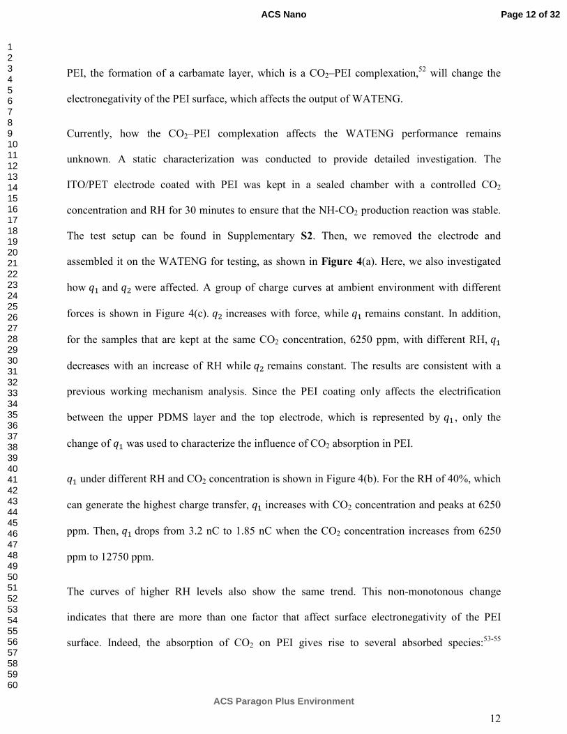
Currently, how the CO2–PEI complexation affects the WATENG performance remains
unknown. A static characterization was conducted to provide detailed investigation. The
ITO/PET electrode coated with PEI was kept in a sealed chamber with a controlled CO2
concentration and RH for 30 minutes to ensure that the NH-CO2 production reaction was stable.
The test setup can be found in Supplementary S2. Then, we removed the electrode and
assembled it on the WATENG for testing, as shown in Figure 4(a). Here, we also investigated
how and were affected. A group of charge curves at ambient environment with different
forces is shown in Figure 4(c). increases with force, while remains constant. In addition,
for the samples that are kept at the same CO2 concentration, 6250 ppm, with different RH,
decreases with an increase of RH while remains constant. The results are consistent with a
previous working mechanism analysis. Since the PEI coating only affects the electrification
between the upper PDMS layer and the top electrode, which is represented by , only the
change of was used to characterize the influence of CO2 absorption in PEI.
under different RH and CO2 concentration is shown in Figure 4(b). For the RH of 40%, which
can generate the highest charge transfer, increases with CO2 concentration and peaks at 6250
ppm. Then, drops from 3.2 nC to 1.85 nC when the CO2 concentration increases from 6250
ppm to 12750 ppm.
The curves of higher RH levels also show the same trend. This non-monotonous change
indicates that there are more than one factor that affect surface electronegativity of the PEI
surface. Indeed, the absorption of CO2 on PEI gives rise to several absorbed species:53-55
Page 12 of 32
ACS Paragon Plus Environment
ACS Nano
123456789101112131415161718192021222324252627282930313233343536373839404142434445464748495051525354555657585960
13
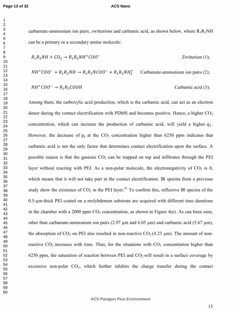
carbamate-ammonium ion pairs, zwitterions and carbamic acid, as shown below, where R1R2NH
can be a primary or a secondary amine molecule:
+ → Zwitterion (1);
+ → +
Carbamate-ammonium ion pairs (2);
→ Carbamic acid (3);
Among them, the carboxylic acid production, which is the carbamic acid, can act as an electron
donor during the contact electrification with PDMS and becomes positive. Hence, a higher CO2
concentration, which can increase the production of carbamic acid, will yield a higher .
However, the decrease of at the CO2 concentration higher than 6250 ppm indicates that
carbamic acid is not the only factor that determines contact electrification upon the surface. A
possible reason is that the gaseous CO2 can be trapped on top and infiltrates through the PEI
layer without reacting with PEI. As a non-polar molecule, the electronegativity of CO2 is 0,
which means that it will not take part in the contact electrification. IR spectra from a previous
study show the existence of CO2 in the PEI layer.51
To confirm this, reflective IR spectra of the
0.5-µm-thick PEI coated on a molybdenum substrate are acquired with different time durations
in the chamber with a 2000 ppm CO2 concentration, as shown in Figure 4(e). As can been seen,
other than carbamate-ammonium ion pairs (2.97 µm and 6.05 µm) and carbamic acid (5.67 µm),
the absorption of CO2 on PEI also resulted in non-reactive CO2 (4.23 µm). The amount of non-
reactive CO2 increases with time. Thus, for the situations with CO2 concentration higher than
6250 ppm, the saturation of reaction between PEI and CO2 will result in a surface coverage by
excessive non-polar CO2, which further inhibits the charge transfer during the contact
Page 13 of 32
ACS Paragon Plus Environment
ACS Nano
123456789101112131415161718192021222324252627282930313233343536373839404142434445464748495051525354555657585960
14
electrification and causes the drop of at a higher range of CO2 concentration. The detailed
testing setup for acquiring IR spectra can be found in Supplementary S3.
Since the CO2 concentration at indoor environment will have a fluctuation from 400 ppm to 2000
ppm, the sensitivity of CO2 sensing of this range is also calculated based on the testing data in
Figure 4(b). The sensitivity is 4.8×10⁻⁴ nC/ppm for 40%RH, 2.28×10⁻⁴ nC/ppm for 53%RH and
1.114×10⁻⁴ nC/ppm for 70%RH. As can be seen, the dry environment can improve the
sensitivity of the triboelectric based sensor.
Dynamic CO2 Sensing
The static characterization only shows the change in with stabilized CO2 absorption in the PEI
layer. However, the capability of CO2 sensing in a dynamic air flow will be more important.
Here, the dynamic CO2 sensing in a gas spray, which mimics exhalation, is characterized. The
testing procedure is shown in Figure 5(a). Before the top electrode is pressed down, a gas spray
with a 1000 ml gas volume with different CO2 concentrations was blown onto the top electrode
with a 1-second duration. The gaseous CO2 will have a temporarily reaction with the PEI
surface. Then, the top electrode was pressed down and lifted up, which generates a charge
transfer curve. A series of charge transfer curves for 11 pulses is shown in Figure 5(c). The CO2
spray of 13000 ppm occurred before the starting point of the 5th pulse. As can been seen, before
the CO2 spray was applied, was approximately 1.23 nC. Based on the calibration of at
different RH with an ambient CO2 concentration of 420 ppm in supplementary information S4,
RH can be estimated as 48%. After the CO2 spray was applied, an increase of was observed in
the 5th pulse. However, recovered to the normal level after the 6th pulse. The period of the
operation cycle is 5 s. Thus, it seems that can recover within 5 s. of each pulse is shown in
Page 14 of 32
ACS Paragon Plus Environment
ACS Nano
123456789101112131415161718192021222324252627282930313233343536373839404142434445464748495051525354555657585960

15
Figure 5(d). The change of , which is , characterizes the CO2 concentration of the applied
gas spray. The value of with a CO2 spray concentration ranging from 420 ppm, which is the
concentration of the ambient environment, to 40000 ppm, which is the CO2 concentration of
exhalation, is shown in Figure 5(b). increases with CO2 within the entire range. However,
the fitting curve indicates that the curve peaks at a concentration between 27000 ppm and 40000
ppm, which means that the data point of 40000 ppm is on the declining trend. The reason is the
same as the decrease of in static characterization. The excessive amount of non-polar CO2
molecules covers the surface and reduces the efficiency of contact electrification. An interesting
point is that can recover to the ambient level in the subsequent pulse after applying the CO2
spray even when the concentration is very high. This is because the complexation of CO2 and
PEI will inhibit further CO2 infiltration 52
. The CO2 trapping and reaction can only occur on the
PEI surface during a short-term gas spray. Without CO2 diffusing into the PEI internal layer, CO2
can detach from the surface and dissipate very fast. The IR spectra of PEI coated on a
molybdenum substrate, which show the change of complexation of CO2 and PEI for the 2000
ppm CO2 gas concentration and ambient environment gas concentration, are shown in Figure
5(e). The black line shows the initial IR spectrum when the chamber is filled with ambient air.
Then, the chamber is filled with a 2000 ppm CO2 gas concentration for 15 s, which is the red
line. Then, the chamber is flushed with ambient air again for another 15 s. The spectrum
recovers, which is shown as the blue line. As can been seen, the black and blue lines fully
overlap, which indicating a complete recovery. The amplitude of reflectivity at 2.97 µm was
recorded with a 3-s time interval, which is the minimum time duration for scanning the IR
spectra, for the entire experiment, as shown in Figure 5(f). As indicated in the figure, when the
sample was exposed to 2000 ppm of CO2, the normalized reflectivity began to rise and peaked
Page 15 of 32
ACS Paragon Plus Environment
ACS Nano
123456789101112131415161718192021222324252627282930313233343536373839404142434445464748495051525354555657585960

16
after 15 s. Then, the chamber was flushed with ambient air for another 15 s. The normalized
reflectivity immediately began to drop with an almost the same rate of increase. This result
shows that the CO2-PEI reaction on the surface can be quickly changed by the environment.
Since the IR spectra scanning requires at least 3 seconds, we do not have a chance to further
investigate the real recovery time if the gas spray only last for 1 s. Considering that in the
dynamic CO2 sensing, the gas spray only lasts for 1 s, the time required for full recovery should
also be 1 or 2 seconds. It should be noted that can also be observed for a CO2 spray at an
ambient concentration, which is 420 ppm. In the test, gas was sprayed at a very high flow rate,
which is 1000 ml/s. Such high flow rate also increases the chance of contact between CO2
molecules and PEI surface, which generating more CO2 and PEI complexation and increases
. This reveals that the mass flow rate should be the real factor that determines .
In summary, and , which are measured during the operation of WATENG, are used to
determine RH and the CO2 concentration, respectively. Considering that RH interferes with the
performance of triboelectric output, with a complete calibration of versus CO2 concentration
for each RH, as shown in Figure 5(b), the WATENG can be used for CO2 sensing for the
environments with different RH. Meanwhile, due to both the upper and lower surfaces of the
dielectric layer are used for electro-static charge coupling, the output energy of the WATENG
can be much enhanced compared with TENGs of conventional structure. With the PEI coating,
the CO2 sensing is characterized at different RH in a static environment. The sensing range can
be up to 6000 ppm. A higher CO2 concentration introduces a non-monotonous effect and causes
a deteriorated sensing result because of the accumulation of excessive CO2 on the surface. A
lower RH leads to a higher triboelectric output, which offers better sensitivity. Hence, for a
continuous CO2 sensing application, a desiccant, which is used to lower the RH surrounding
Page 16 of 32
ACS Paragon Plus Environment
ACS Nano
123456789101112131415161718192021222324252627282930313233343536373839404142434445464748495051525354555657585960

17
environment of WATENG, can enhance the responsivity and sensitivity. The dynamic CO2
sensing of a pulse gas spray is also demonstrated. Compared with the static situation, the sensing
range of the dynamic situation can be broadened to 30000 ppm. The output tends to saturate
when the CO2 concentration is higher than 30000 ppm. In the dynamic testing, the ambient RH
can also be measured when the ambient CO2 concentration is a constant value, which is
approximately 420 ppm. With the characterization of at the CO2 concentration of 420 ppm,
this dynamic testing manner is useful for the environments with various relative humidity. Thus
the structure of WATENG enables itself as a self-powered amenity sensor.
Page 17 of 32
ACS Paragon Plus Environment
ACS Nano
123456789101112131415161718192021222324252627282930313233343536373839404142434445464748495051525354555657585960
18
ASSOCIATED CONTENT
Supporting Information
S1. Detailed fabrication process, optical and SEM images of the WATENG
S2. Testing chamber to control the humidity, CO2 concentration for static characterization.
S3. Testing setup for obtaining IR spectra
S4. Calibration of at ambient CO2 concentration (420 ppm) with different RH
Funding Sources
This work was supported by grants from the National Research Foundation (NRF) CRP project
‘Self-Powered Body Sensor Network for Disease Management and Prevention Oriented
Healthcare’ (R-263-000-A27-281), Ministry of Education (MOE) Faculty Research Committee
(FRC) Grant (R-263-000-B56-112) “Thermoelectric Power Generator (TEG)-Based Self-
Powered ECG Plaster – System Integration (Part 3)” and the National Natural Science
Foundation of China under Grant No. 61474078 at NUS (Suzhou) Research Institute, Suzhou,
China.
REFERENCES
[1] Hoy, Matthew B. Smart buildings: An Introduction to The Library of The Future. Med. Ref.
Serv. Q. 2016, 35, 326-331.
[2] Abeysinghe, Don C., Samhita Dasgupta, Howard E. Jackson, and Joseph T. Boyd. Novel
MEMS Pressure and Temperature Sensors Fabricated on Optical Fibers. J. Micromech.
Microeng. 2002,12, 229.
Page 18 of 32
ACS Paragon Plus Environment
ACS Nano
123456789101112131415161718192021222324252627282930313233343536373839404142434445464748495051525354555657585960

19
[3] Chen, Lung-Tai, Chia-Yen Lee, and Wood-Hi Cheng. MEMS-Based Humidity Sensor with
Integrated Temperature Compensation Mechanism. Sens. Actuators, A. 2008, 147, 522-528.
[4] Dai, Ching-Liang. A Capacitive Humidity Sensor Integrated with Micro Heater and Ring
Oscillator Circuit Fabricated by CMOS–MEMS Technique. Sens. Actuators, B. 2007, 122, 375-
380.
[5] Dai, Ching-Liang, Mao-Chen Liu, Fu-Song Chen, Chyan-Chyi Wu, and Ming-Wei Chang. A
Nanowire WO3 Humidity Sensor Integrated with Micro-Heater and Inverting Amplifier Circuit
on Chip Manufactured Using CMOS-MEMS Technique. Sens. Actuators, B. 2007, 123, 896-901.
[6] Mutschall, D., and E. Obermeier. A Capacitive CO2 Sensor With On-Chip Heating. Sens.
Actuators, B. 1995, 25, 412-414.
[7] Bang, Yeung-Il, Kap-Duk Song, Byung-Su Joo, Jeung-Soo Huh, Soon-Don Choi, and Duk-
Dong Lee. Thin Film Micro Carbon Dioxide Sensor Using MEMS Process. Sens. Actuators, B.
2004, 102, 20-26.
[8] Wang, Sihong, Long Lin, and Zhong Lin Wang. Triboelectric Nanogenerators as Self-
Powered Active Sensors. Nano Energy. 2005, 11, 436-462.
[9] Wang, Zhong Lin. Self-Powered Nanosensors and Nanosystems. Adv. Mater. 2012, 24, 280-
285.
[10] Wang, Zhong Lin. Self-Powered Nanotech. Sci. Am. 2008, 298, 82-87.
Page 19 of 32
ACS Paragon Plus Environment
ACS Nano
123456789101112131415161718192021222324252627282930313233343536373839404142434445464748495051525354555657585960

20
[11] Wang, Zhong Lin. Triboelectric Nanogenerators as New Energy Technology for Self-
Powered Systems and as Active Mechanical and Chemical Sensors. ACS Nano. 2013, 7, 9533-
9557.
[12] Fan, Feng-Ru, Zhong-Qun Tian, and Zhong Lin Wang. Flexible Triboelectric Generator.
Nano Energy. 2012, 1, 328-334.
[13] Cao, Xia, Yang Jie, Ning Wang, and Zhong Lin Wang. Triboelectric Nanogenerators Driven
Self-Powered Electrochemical Processes for Energy and Environmental Science. Adv. Energy
Mater. 2016.
[14] Chen, Shu Wen, Xia Cao, Ning Wang, Long Ma, Hui Rui Zhu, Magnus Willander, Yang
Jie, and Zhong Lin Wang. An Ultrathin Flexible Single-Electrode Triboelectric-Nanogenerator
for Mechanical Energy Harvesting and Instantaneous Force Sensing. Adv. Energy Mater. 2017,
7.
[15] Xi, Yi, Hengyu Guo, Yunlong Zi, Xiaogan Li, Jie Wang, Jianan Deng, Shengming Li,
Chenguo Hu, Xia Cao, and Zhong Lin Wang. Multifunctional TENG for Blue Energy
Scavenging and Self-Powered Wind-Speed Sensor. Adv. Energy Mater. 2017, 7.
[16] Chen, Shuwen, Ning Wang, Long Ma, Tao Li, Magnus Willander, Yang Jie, Xia Cao, and
Zhong Lin Wang. Triboelectric Nanogenerator for Sustainable Wastewater Treatment via a
Self‐Powered Electrochemical Process. Adv. Energy Mater. 2017, 6.
[17] Li, Tao, Ying Xu, Fei Xing, Xia Cao, Jie Bian, Ning Wang, and Zhong Lin Wang. Boosting
Photoelectrochemical Water Splitting by TENG-Charged Li-Ion Battery. Adv. Energy Mater.
2017, 7.
Page 20 of 32
ACS Paragon Plus Environment
ACS Nano
123456789101112131415161718192021222324252627282930313233343536373839404142434445464748495051525354555657585960
21
[18] Jiang, Jian, Mei Wang, Wensheng Yan, Xiaofeng Liu, Jinxuan Liu, Jinlong Yang, and
Licheng Sun. Highly Active and Durable Electrocatalytic Water Oxidation by a NiB0.45/NiOx
Core-Shell Heterostructured Nanoparticulate Film. Nano Energy. 2017, 38, 175-184.
[19] Yu, Aifang, Peng Jiang, and Zhong Lin Wang. Nanogenerator as Self-powered Vibration
Sensor. Nano Energy. 2012, 1, 418-423.
[20] Lin, Long, Yannan Xie, Sihong Wang, Wenzhuo Wu, Simiao Niu, Xiaonan Wen, and
Zhong Lin Wang. Triboelectric Active Sensor Array for Self-Powered Static and Dynamic
Pressure Detection and Tactile Imaging. ACS Nano. 2013, 7, 8266-8274.
[21] Fan, Feng-Ru, Long Lin, Guang Zhu, Wenzhuo Wu, Rui Zhang, and Zhong Lin Wang.
Transparent Triboelectric Nanogenerators and Self-Powered Pressure Sensors Based on
Micropatterned Plastic Films. Nano Lett. 2012, 12, 3109-3114.
[22] Zhu, Guang, Wei Qing Yang, Tiejun Zhang, Qingshen Jing, Jun Chen, Yu Sheng Zhou,
Peng Bai, and Zhong Lin Wang. Self-Powered, Ultrasensitive, Flexible Tactile Sensors Based on
Contact Electrification. Nano Lett. 2014, 14, 3208-3213.
[23] Yang, Ya, Hulin Zhang, Zong-Hong Lin, Yu Sheng Zhou, Qingshen Jing, Yuanjie Su, Jin
Yang, Jun Chen, Chenguo Hu, and Zhong Lin Wang. Human Skin Based Triboelectric
Nanogenerators for Harvesting Biomechanical Energy and as Self-Powered Active Tactile
Sensor System. ACS Nano. 2013, 7, 9213-9222.
[24] Meng, Bo, Wei Tang, Zhi-han Too, Xiaosheng Zhang, Mengdi Han, Wen Liu, and Haixia
Zhang. A Transparent Single-Friction-Surface Triboelectric Generator and Self-Powered Touch
Sensor. Energy Environ. Sci. 2013, 6, 3235-3240.
Page 21 of 32
ACS Paragon Plus Environment
ACS Nano
123456789101112131415161718192021222324252627282930313233343536373839404142434445464748495051525354555657585960
22
[25] Yang, Ya, Hulin Zhang, Xiandai Zhong, Fang Yi, Ruomeng Yu, Yue Zhang, and Zhong Lin
Wang. Electret Film-Enhanced Triboelectric Nanogenerator Matrix for Self-Powered
Instantaneous Tactile Imaging. ACS Appl. Mater. Interfaces. 2014, 6, 3680-3688.
[26] Gupta, Rahul Kumar, Qiongfeng Shi, Lokesh Dhakar, Tao Wang, Chun Huat Heng, and
Chengkuo Lee. Broadband Energy Harvester Using Non-linear Polymer Spring and
Electromagnetic/Triboelectric Hybrid Mechanism. Sci. Rep. 2017, 7, 41396
[27] Yang, Weiqing, Jun Chen, Xiaonan Wen, Qingshen Jing, Jin Yang, Yuanjie Su, Guang Zhu,
Wenzuo Wu, and Zhong Lin Wang. Triboelectrification Based Motion Sensor for Human-
Machine Interfacing. ACS Appl. Mater. Interfaces. 2014, 6, 7479-7484.
[28] Zhang, Limin, Fei Xue, Weiming Du, Changbao Han, Chi Zhang, and Zhonglin Wang.
Transparent Paper-Based Triboelectric Nanogenerator as a Page Mark and Anti-Theft Sensor.
Nano Res. 2014, 7, 1215-1223.
[29] Bai, Peng, Guang Zhu, Qingshen Jing, Jin Yang, Jun Chen, Yuanjie Su, Jusheng Ma, Gong
Zhang, and Zhong Lin Wang. Membrane-Based Self-Powered Triboelectric Sensors for Pressure
Change Detection and Its Uses in Security Surveillance and Healthcare Monitoring. Adv. Funct.
Mater. 2014, 24, 5807-5813.
[30] Lin, Long, Sihong Wang, Yannan Xie, Qingshen Jing, Simiao Niu, Youfan Hu, and Zhong
Lin Wang. Segmentally Structured Disk Triboelectric Nanogenerator for Harvesting Rotational
Mechanical Energy. Nano Lett. 2013, 13, 2916-2923.
Page 22 of 32
ACS Paragon Plus Environment
ACS Nano
123456789101112131415161718192021222324252627282930313233343536373839404142434445464748495051525354555657585960
23
[31] Lin, Long, Sihong Wang, Simiao Niu, Chang Liu, Yannan Xie, and Zhong Lin Wang.
Noncontact Free-rotating Disk Triboelectric Nanogenerator as a Sustainable Energy Harvester
and Self-Powered Mechanical Sensor. ACS Appl. Mater. Interfaces. 2014, 6, 3031-3038.
[32] Yang, Ya, Hulin Zhang, Jun Chen, Qingshen Jing, Yu Sheng Zhou, Xiaonan Wen, and
Zhong Lin Wang. Single-Electrode-Based Sliding Triboelectric Nanogenerator for Self-Powered
Displacement Vector Sensor System. ACS Nano. 2013, 7, 7342-7351.
[33] Wang, Hao, Zhuolin Xiang, Pastorin Giorgia, Xiaojing Mu, Ya Yang, Zhong Lin Wang, and
Chengkuo Lee. Triboelectric Liquid Volume Sensor for Self-Powered Lab-On-Chip
Applications. Nano Energy. 2016, 23, 80-88.
[34] Shi, Qiongfeng, Hao Wang, Tao Wang, and Chengkuo Lee. Self-Powered Liquid
Triboelectric Microfluidic Sensor for Pressure Sensing and Finger Motion Monitoring
Applications. Nano Energy. 2016, 30, 450-459.
[35] Lin, Zong‐Hong, Guang Zhu, Yu Sheng Zhou, Ya Yang, Peng Bai, Jun Chen, and Zhong
Lin Wang. A Self-Powered Triboelectric Nanosensor for Mercury Ion Detection. Angew. Chem.,
Int. Ed. 2013, 52, 5065-5069.
[36] Lin, Zong-Hong, Yannan Xie, Ya Yang, Sihong Wang, Guang Zhu, and Zhong Lin Wang.
Enhanced Triboelectric Nanogenerators and Triboelectric Nanosensor Using Chemically
Modified TiO2 Nanomaterials. ACS Nano. 2013, 7, 4554-4560.
[37] Zhang, H., Fawang Liu, Mantha S. Phanikumar, and Mark M. Meerschaert. A Novel
Numerical Method for the Time Variable Fractional Order Mobile-Immobile Advection-
Dispersion Model. Comput. Math. Appl. 2013, 66, 693-701.
Page 23 of 32
ACS Paragon Plus Environment
ACS Nano
123456789101112131415161718192021222324252627282930313233343536373839404142434445464748495051525354555657585960

24
[38] Lin, Zong-Hong, Gang Cheng, Wenzhuo Wu, Ken C. Pradel, and Zhong Lin Wang. Dual-
Mode Triboelectric Nanogenerator for Harvesting Water Energy and as a Self-Powered Ethanol
Nanosensor. ACS Nano. 2014, 8, 6440-6448.
[39] Lin, Zong‐Hong, Gang Cheng, Ya Yang, Yu Sheng Zhou, Sangmin Lee, and Zhong Lin
Wang. Triboelectric Nanogenerator as an Active UV Photodetector. Adv. Funct. Mater. 2014,
24, 2810-2816.
[40] Uddin, ASM Iftekhar, and Gwiy-Sang Chung. Wide-Ranging Impact-Competent Self-
Powered Active Sensor Using a Stacked Corrugated-Core Sandwich-Structured Robust
Triboelectric Nanogenerator. Sens. Actuators, B. 2017, 245, 1-10.
[41] Baytekin, H. Tarik, Bilge Baytekin, Siowling Soh, and Bartosz A. Grzybowski. Is Water
Necessary for Contact Electrification? Angew. Chem., Int. Ed. 2011, 50, 6766-6770.
[42] Nguyen, Vu, and Rusen Yang. Effect of Humidity and Pressure on the Triboelectric
Nanogenerator. Nano Energy. 2013, 2, 604-608.
[43] Zhang, Hulin, Ya Yang, Yuanjie Su, Jun Chen, Chenguo Hu, Zhenkun Wu, Yan Liu, Ching
Ping Wong, Yoshio Bando, and Zhong Lin Wang. Triboelectric Nanogenerator as Self-Powered
Active Sensors for Detecting Liquid/Gaseous Water/Ethanol. Nano Energy. 2013, 2, 693-701.
[44] Hodgkinson, J., R. Smith, W. O. Ho, J. R. Saffell, and R. P. Tatam. A Low Cost, Optically
Efficient Carbon Dioxide Sensor Based on Non-Dispersive Infra-Red (NDIR) Measurement at
4.2 µm. In Proc. SPIE. 2012, 8439, 843919.
Page 24 of 32
ACS Paragon Plus Environment
ACS Nano
123456789101112131415161718192021222324252627282930313233343536373839404142434445464748495051525354555657585960
25
[45] Hodgkinson, Jane, and Ralph P. Tatam. Optical Gas Sensing: A Review. Meas. Sci.
Technol. 2012, 24, 012004.
[46] Willa, Christoph, Jiayin Yuan, Markus Niederberger, and Dorota Koziej. When
Nanoparticles Meet Poly (Ionic Liquid) s: Chemoresistive CO2 Sensing at Room Temperature.
Adv. Funct. Mater. 2015, 25, 2537-2542.
[47] Endres, Hanns-Erik, Ralf Hartinger, Markus Schwaiger, Gerhard Gmelch, and Mathias
Roth. A Capacitive CO2 Sensor System with Suppression of the Humidity Interference. Sens.
Actuators, B. 1999, 57, 83-87.
[48] Zhou, R., D. Schmeisser, and W. Göpel. Mass Sensitive Detection of Carbon Dioxide by
Amino Group-Functionalized Polymers. Sens. Actuators, B. 1996, 33, 188-193.
[49] Yang, Ya, Yu Sheng Zhou, Hulin Zhang, Ying Liu, Sangmin Lee, and Zhong Lin Wang. A
Single-Electrode Based Triboelectric Nanogenerator as Self-Powered Tracking System. Adv.
Mater. 2013, 25, 6594-6601.
[50] Zhong, Junwen, Qize Zhong, Fengru Fan, Yan Zhang, Sihong Wang, Bin Hu, Zhong Lin
Wang, and Jun Zhou. Finger Typing Driven Triboelectric Nanogenerator and Its Use for
Instantaneously Lighting Up LEDs. Nano Energy. 2013, 2, 491-497.
[51] Moumen, Sarra, Isabelle Raible, Andreas Krauß, and Jürgen Wöllenstein. Infrared
Investigation of CO2 Sorption by Amine Based Materials for the Development of a NDIR CO2
Sensor. Sens. Actuators, B. 2016, 236, 1083-1090.
Page 25 of 32
ACS Paragon Plus Environment
ACS Nano
123456789101112131415161718192021222324252627282930313233343536373839404142434445464748495051525354555657585960
26
[52] Zhao, Junqi, Fritz Simeon, Yujun Wang, Guangsheng Luo, and T. Alan Hatton.
Polyethylenimine-Impregnated Siliceous Mesocellular Foam Particles as High Capacity CO2
Adsorbents. RSC Adv. 2012, 2, 6509-6519.
[53] Hahn, Maximilian W., Matthias Steib, Andreas Jentys, and Johannes A. Lercher.
Mechanism and Kinetics of CO2 Adsorption on Surface Bonded Amines. J. Phys. Chem. C.
2015, 119, 4126-4135.
[54] Wilfong, Walter Christopher, Chakravartula S. Srikanth, and Steven SC Chuang. In situ
ATR and DRIFTS Studies of the Nature of Adsorbed CO2 on Tetraethylenepentamine Films.
ACS Appl. Mater. Interfaces. 2014, 6, 13617-13626.
[55] Wang, Xiaoxing, Viviane Schwartz, Jason C. Clark, Xiaoliang Ma, Steven H. Overbury,
Xiaochun Xu, and Chunshan Song. Infrared Study of CO2 Sorption over Molecular Basket
Sorbent Consisting of Polyethylenimine-Modified Mesoporous Molecular Sieve. J. Phys. Chem.
C. 2009, 113, 7260-7268.
Page 26 of 32
ACS Paragon Plus Environment
ACS Nano
123456789101112131415161718192021222324252627282930313233343536373839404142434445464748495051525354555657585960
27
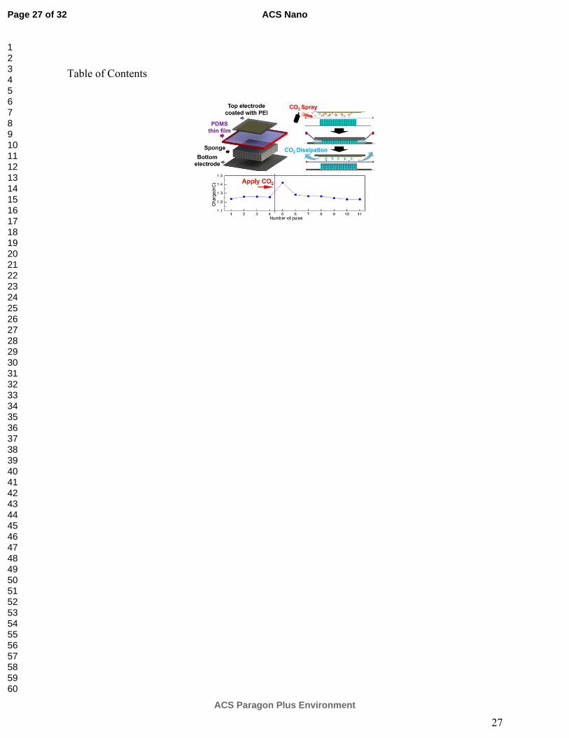
Table of Contents
Page 27 of 32
ACS Paragon Plus Environment
ACS Nano
123456789101112131415161718192021222324252627282930313233343536373839404142434445464748495051525354555657585960

Figure 1. (a) Illustration of the WATENG layer structure; (b) schematic diagram that shows the concept of the WATENG-based CO2 sensor, which is comprised of a PEI layer with an interference of humidity.
57x19mm (600 x 600 DPI)
Page 28 of 32
ACS Paragon Plus Environment
ACS Nano
123456789101112131415161718192021222324252627282930313233343536373839404142434445464748495051525354555657585960

Figure 2. (a) Working mechanism of the WANTENG; (b) the total charge transferred with different RH, force and water volume; (c) a typical charge curve during the operation; (d) the value of q1 with different RH,
force and water volume; (e) the value of q2 with different RH, force and water volume; (f) a group of charge
curves showing q2 was not affected by RH (Force=2.7 N; water volume=1.75 ml).
107x69mm (600 x 600 DPI)
Page 29 of 32
ACS Paragon Plus Environment
ACS Nano
123456789101112131415161718192021222324252627282930313233343536373839404142434445464748495051525354555657585960

Figure 3. Comparison of the output between different kinds of structures. (a) Different structure and the voltage output with 100MΩ load resistance; (b) The average voltage output of the 5 cases in (a); (c) The
output power and voltage characterization of the conventional TENGs (case-1) and WATENG(case-5).
155x141mm (300 x 300 DPI)
Page 30 of 32
ACS Paragon Plus Environment
ACS Nano
123456789101112131415161718192021222324252627282930313233343536373839404142434445464748495051525354555657585960
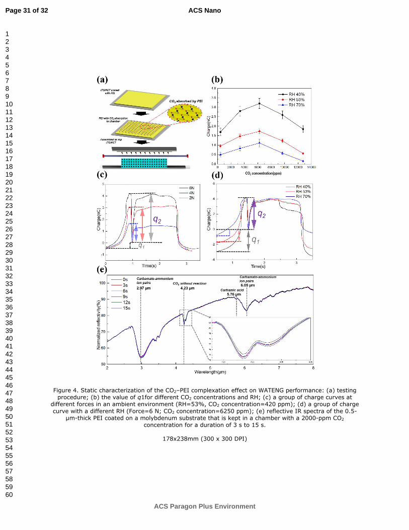
Figure 4. Static characterization of the CO2–PEI complexation effect on WATENG performance: (a) testing procedure; (b) the value of q1for different CO2 concentrations and RH; (c) a group of charge curves at
different forces in an ambient environment (RH=53%, CO2 concentration=420 ppm); (d) a group of charge
curve with a different RH (Force=6 N; CO2 concentration=6250 ppm); (e) reflective IR spectra of the 0.5-µm-thick PEI coated on a molybdenum substrate that is kept in a chamber with a 2000-ppm CO2
concentration for a duration of 3 s to 15 s.
178x238mm (300 x 300 DPI)
Page 31 of 32
ACS Paragon Plus Environment
ACS Nano
123456789101112131415161718192021222324252627282930313233343536373839404142434445464748495051525354555657585960

Figure 5. Dynamic CO2 concentration characterization: (a) testing procedure; (b) the value of ∆q1 with a gas spray of different CO2 concentrations at an ambient environment; (c) charge transfer curve showing the change of q1 when the PEI surface was blown with a CO2 spray; (d) the value of q1 of each pulse in (c); (e)
IR spectra of PEI coated on a molybdenum substrate: black line (overlapped with the blue line) is the initial IR spectrum when the chamber is filled with ambient air; red line- is the IR spectrum when the chamber is filled with 2000 ppm CO2 gas concentration; blue line is the IR spectrum when the chamber is flushed again
with ambient air; (f) the normalized reflectivity at 2.97 µm for the entire experiment shown in (e) with a time interval of 3 s.
191x285mm (300 x 300 DPI)
Page 32 of 32
ACS Paragon Plus Environment
ACS Nano
123456789101112131415161718192021222324252627282930313233343536373839404142434445464748495051525354555657585960