Self-Organizing Small Cell Networksdrmoe.org/ieee/EkramTalk2015.pdfSelf-Organizing Small Cell...
73
Self-Organizing Small Cell Networks Ekram Hossain, IEEE Fellow Department of Electrical and Computer Engineering University of Manitoba, Winnipeg, Canada http://home.cc.umanitoba.ca/∼hossaina IEEE ComSoc DL 31 March 2015 1/73
Transcript of Self-Organizing Small Cell Networksdrmoe.org/ieee/EkramTalk2015.pdfSelf-Organizing Small Cell...

Self-Organizing Small Cell Networks
Ekram Hossain, IEEE Fellow
Department of Electrical and Computer EngineeringUniversity of Manitoba, Winnipeg, Canadahttp://home.cc.umanitoba.ca/∼hossaina
IEEE ComSoc DL31 March 2015
1/73
Outline
Overview of small cell networks (SCNs)
Self-organization in SCNs
Survey on self-organization in SCNs
Cognitive spectrum access by small cells
Future research directions
2/73

Overview of SCNs
Introduction and motivation - small cells and HetNet
Use cases for small cells
Small cell specifications
Licensed small cells vs. Wi-Fi
Access modes (e.g., closed, open, and hybrid)
Small cells in LTE/LTE-Advanced architecture
Small cell deployment models
Technical challenges in small cell deployment
3/73

Introduction and motivation
Exponential increase of the population of wireless devices withubiquitous Internet connectivity (which is expected to reach50 billion by 2020)
Evolution phases: connected consumer electronics phase,connected industry phase, and connected everything (IoT)phase
Nu
mb
er o
f co
nn
ecte
d d
evic
es
2020
10b
20b
30b
40b
50b
2015 2010
4/73

Introduction and motivation
Significant challenge to the existing cellular wirelessinfrastructure
Traditional capacity expansion techniques (e.g., cell splitting)are insufficient and introduce a huge CAPEX.
Small cells may provide a fast, flexible, and cost-efficientsolution to fulfill the gap between capacity and demand tocope with the fast growth in wireless traffic.
Low-powered radio access nodes which can operate in licensedand/or unlicensed spectrum bands and have a transmissionrange of several tens to several hundreds of meters
5/73
Introduction and motivation
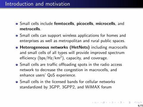
Small cells include femtocells, picocells, microcells, andmetrocells.
Small cells can support wireless applications for homes andenterprises as well as metropolitan and rural public spaces.
Heterogeneous networks (HetNets) including macrocellsand small cells of all types will provide improved spectrumefficiency (bps/Hz/km2), capacity, and coverage.
Small cells are traffic offloading spots in the radio accessnetwork to decrease the congestion in macrocells, andenhance users’ QoS experience.
Small cells in the licensed bands for cellular networksstandardized by 3GPP, 3GPP2, and WiMAX forum
6/73

Introduction and motivation
A heterogeneous cellular wireless network:
FemtocellPicocell
Femtocell
Femtocell
PicocellPicocell
Relay
Relay
Relay
Macrocell
Internet
Mobile Core Network
User Broadband Connection
D2D
D2D
D2D
D2D
UE
UE
UE
UE
UE
E. Hossain, M. Rasti, H. Tabassum, and A. Abdelnasser, “Evolution towards 5Gmulti-tier cellular wireless networks: An interference management perspective,” IEEEWireless Communications, vol. 21, no. 3, pp. 118–127, 2014
7/73

Introduction and motivation
Different types of small cells:
Femtocell: small area covered by a small base station, calledthe femto access point (FAP), intended for residential indoorapplications, installed and managed by the customers
Key attributes: IP backhaul, self-optimization, low powerconsumption, ease of deployment (user-deployed),closed/open/hybrid access
Picocell: low-power compact base stations, used in enterpriseor public indoor areas, sometimes encompasses outdoor smallcells as well
Key attributes: wired or wireless backhaul, operatordeployed, self-optimization, open access
8/73
Introduction and motivation
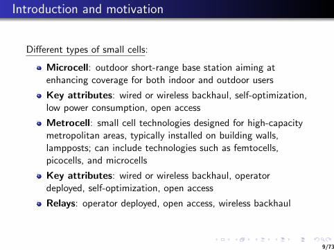
Different types of small cells:
Microcell: outdoor short-range base station aiming atenhancing coverage for both indoor and outdoor users
Key attributes: wired or wireless backhaul, self-optimization,low power consumption, open access
Metrocell: small cell technologies designed for high-capacitymetropolitan areas, typically installed on building walls,lampposts; can include technologies such as femtocells,picocells, and microcells
Key attributes: wired or wireless backhaul, operatordeployed, self-optimization, open access
Relays: operator deployed, open access, wireless backhaul
9/73

Introduction and motivation
Due to their limited coverage, small cells will have unplanneddeployment with high densities (hence complete centralizedcontrol may be infeasible).
Small cells need to have the Self-Organizing Network (SON)capabilities (through cognition) for efficient operation withlimited centralized control.
Cognitive small cell base stations (SBSs) will be capable ofmonitoring the surrounding environment, locate majorinterference sources, and avoid them by opportunisticallyaccessing the orthogonal channels.
To be robust and adaptive to topological changes, the designparameters (e.g., spectrum sensing threshold) for cognitiveSBSs should be independent from the topology and accountfor the topological randomness.
10/73

Use cases for small cells
Residential: femtocell concept (a standalone self-configuring,low-power compact BS connected through broadbandInternet), 4-8 active users per BS
Enterprise: larger BSs with higher RF power (longer range)and higher traffic capacity, 8-32 concurrent users per BS
Metro and public space: for urban and rural environmentsto serve the hotspots, higher traffic capacity (16-64concurrent users per BS), relatively short range
11/73

Small cell specifications
Attribute MeNB Picocell HeNB Wi-Fi
Coverage Wide area Hot spot Hot spot Hot spotType of Outdoor Outdoor, Indoor Indoorcoverage indoorDensity Low High High High
BS installation Operator Operator Subscriber CustomerSite acquisition Operator Operator Subscriber Customer
Tx. range 300-2000m 40-100m 10-30m 100-200mTx. 40W (approx.) 200mW- 2W 10-100mW 100-200mW
powerBand license Licensed Licensed Licensed Unlicensed
System 5, 10, 5, 10, 5, 10, 5, 10,bandwidth 15, 20MHz 15, 20MHz 15, 20MHz 20MHz
(upto 100MHz) (upto 100MHz) (upto 100MHz)Tx. rate upto 1Gbps upto 300Mbps 100Mbps-1Gbps upto 600Mbps
Cost $60,000/yr $10,000/yr $200/yr $100-200/yr(approx.)
Power High Moderate Low Lowconsump.Backhaul S1 interface X2 interface IP IPMobility Seamless Nomadic Nomadic Nomadic
QoS High High High Best-effort
12/73

Small cell specifications
Heterogeneous (small cell) networks operate on licensedspectrum owned by the mobile operator
Fundamentally different from macrocells since they need to beautonomous and self-organizing and self-adaptive to maintainlow costs
Femtocells are connected to the operator throughDSL/cable/ethernet connection.
Picocells have dedicated backhauls since deployed by operators
Relays are essentially used for coverage extension.
Heterogeneous (wired,wireless, and mix) backhauls areenvisioned.
13/73

Small cells in the LTE/LTE-Advanced architecture
LTE/LTE-A HetNet:
!
IEEE Wireless Communications • June 201112
cy resource blocks within a carrier or differentcarriers (if available) to their respective UE.This is one of the intercell interference coordi-nation (ICIC) techniques that can be used onthe downlink to mitigate data interference [14,15]. With additional complexity, joint processingof serving and interfering base station signalscould further improve the performance of het-erogeneous networks [16, 17], but these tech-niques require further study for the scenarioscommonly seen in practice.
For those reasons, in the context of LongTerm Evolution (LTE) standardization, theThird Generation Partnership Project (3GPP) isdiscussing the concept of cell range expansionthrough handover biasing and resource partition-ing among different node power classes. Thebiasing mechanism allows for load balancing,where depending on the bias value, the networkcan control the number of UE units associatedwith the low-power nodes and therefore controltraffic demand at those nodes. Resource parti-tioning, which can also be adaptive, allows con-figuration and adjustment of interferenceprotected resources, enabling UE in a cellexpanded area to receive data. Moreover, thesame resource partitioning technique provides amechanism to mitigate uplink interference andallows non-CSG member UE to receive servicewhen in proximity of closed femtocells.
The main goal of this article is to provide anoverview of the topology and the deploymentoptions for heterogeneous networks. We focuson LTE downlink, where we review the currentstate of the art, describe technical challenges,and give some thoughts on future research direc-tions. Uplink data transmissions are slaved tothe downlink control channel, and interferencemanagement techniques enabled to partitiondownlink resources apply to the uplink transmis-sions too.
LTE OVERVIEWThe first release of LTE was published in March2009 and is referred to as LTE Rel-8 [18]. 3GPPhas developed the LTE standard for fourth-gen-eration (4G) cellular networks based on orthog-onal frequency-division multiplexing (OFDM)waveform for downlink (DL) and single-carrierFDM (SC-FDM) waveform for uplink (UL)communications mainly to improve the userexperience for broadband data communications.Compared to 3G technologies, such as 3GPP’sHSPA,1 LTE Rel-8 offers higher peak data ratesdue to larger system bandwidth (up to 20 MHzwas allowed) and higher-order multiple-inputmultiple-output (MIMO) spatial processing tech-niques (up to 4 Tx ! 4 Rx open and closed loopMIMO schemes are supported in the DL ofLTE Rel-8).
Figure 2 illustrates the LTE network [18]nodes and the interfaces among them. The basestations are denoted eNode-B (eNB) and themobile stations or terminals as UE. The low-power nodes include picocells, femtocells, homeeNBs (HeNBs), and relay nodes (RNs). TheeNB serving the RN (i.e., scheduling RN back-haul traffic) is denoted donor eNB (DeNB). Thesame eNB can be the DeNB for one RN and theregular serving cell for UE, as shown in Fig. 2.The mobility management entity (MME) andserving gateway (S-GW) serve as local mobilityanchor points for the control and data planes,respectively.
The X2 interface defined as a direct eNB-to-eNB interface allows for inter-cell interferencecoordination (ICIC). The Rel-8 ICIC techniquescan be summarized as:• Proactive: Techniques that facilitate fractional
frequency reuse (FFR) or “soft reuse” opera-tion in the DL and UL with the goal of reduc-ing interference experienced in certain
Figure 2. LTE heterogeneous network nodes and their interfaces.
RN
UE
UE
UE
Pico Pico
HeNBHeNB HeNB
HeNB GWE-UTRAN
UE
UE
eNB
DeNB
MME / S-GWMME / S-GW
X2
X2
S1 S1
S1X2 S1
S1S1
S1 S1
S1
S1
S1
S1X2Un
S11
1 HSPA Rel-10 supportscarrier aggregation mode,where four 5 MHz can beaggregated offering broad-band wireless communi-cation to a single UE over20 MHz bandwidth.
Compared to 3Gtechnologies, such as3GPP’s HSPA, LTERel-8 offers higherpeak data rates dueto larger systembandwidth (up to 20MHz was allowed)and higher-orderMIMO spatial processing techniques.
DAMNJANOVIC LAYOUT 6/6/11 10:56 AM Page 12
A. Damnjanovic et al., “A survey on 3GPP heterogeneous networks,” IEEE Wireless Comm., June 2011.
14/73
Small cells in the LTE/LTE-Advanced architecture
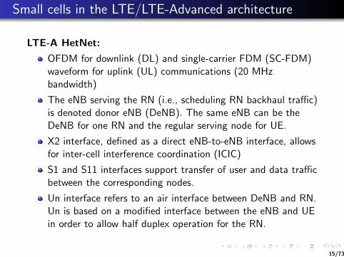
LTE-A HetNet:
OFDM for downlink (DL) and single-carrier FDM (SC-FDM)waveform for uplink (UL) communications (20 MHzbandwidth)
The eNB serving the RN (i.e., scheduling RN backhaul traffic)is denoted donor eNB (DeNB). The same eNB can be theDeNB for one RN and the regular serving node for UE.
X2 interface, defined as a direct eNB-to-eNB interface, allowsfor inter-cell interference coordination (ICIC)
S1 and S11 interfaces support transfer of user and data trafficbetween the corresponding nodes.
Un interface refers to an air interface between DeNB and RN.Un is based on a modified interface between the eNB and UEin order to allow half duplex operation for the RN.
15/73

Licensed small cells vs. Wi-Fi
Support for legacy handsets
Operator managed QoS
Seamless continuity with the macro networks through bettersupport for mobility/handoff
Improved security
Increased development of small cells that combine bothlicensed and unlicensed technologies
16/73

Access modes for small cells
Closed access mode: A set of registered users belonging toClosed Subscriber Group (CGS) is allowed to access afemtocell (e.g., residential deployment scenario).
Co-channel deployments of closed femtocells cause coverageholes.
Open access mode: Any user can connect to a small cell (e.g.,can be used for public places like airports, shopping mallsetc.).
Hybrid access mode: A small cell may allow up to Nnon-registered mobile users to access it (to limit the load onthe base station and its backhaul connection); can be used insmall business or enterprise deployment scenario
Femtocells generally use closed, open, or hybrid access modewhile picocells usually use the open access mode.
17/73

Small cells in the LTE/LTE-Advanced architecture
LTE-A HetNet:
OFDM (SC-FDM) symbols are grouped in subframes of 1 msduration. Each subframe is composed of two 0.5 ms slots.
Minimum scheduling unit for the DL and UL of LTE isreferred to as a resource block (RB).
One RB consists of 12 subcarriers in the frequency domain(180 kHz) and one subframe in the time domain (1 ms).
Subframes are further grouped in 10 ms radio frames.
A reference or pilot signal, referred to as a common referencesignal (CRS), is used for mobility measurements as well as fordemodulation of the DL control and data channels.
CRS transmission is distributed in time and frequency.
18/73

Small cells in the LTE/LTE-Advanced architecture
LTE HetNet:
LTE Rel-10 (or LTE- Advanced) supports improved MIMOoperation as DL MIMO support is enhanced (8 Tx, 8Rx issupported), and UL MIMO (4Tx, 4 Rx) is introduced toimprove link spectral efficiency.
Up to five 20-MHz component carriers can be aggregated,offering a peak data rate of more than 1 Gb/s
Do not translate into significant improvements in terms ofsystem spectral efficiency in bits per second per Hertz.
System gains are only achievable through increased nodedensity and deployment of low-power nodes, such as pico,femto, and relay base stations.
19/73

Small cell deployment models
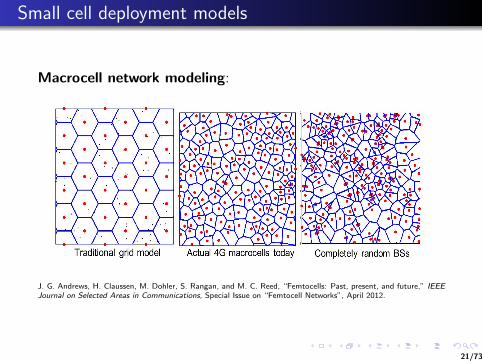
Macrocell network modeling:
Hexagonal grid model (easy to simulate) along with outdoorchannel model (path-loss, shadowing, and fading) formacrocells
Random i.i.d. placements of macrocell base stations(analytically tractable, easy to integrate femtocells, relaysetc.)
Real-world macrocell deployment is in between a fullydeterministic grid and a fully random placement.
20/73
Small cell deployment models
Macrocell network modeling:
!
5
(a) (b) (c)
Fig. 2: Example of different macrocell only models. Traditional grid networks remain the most popular, but 4G systems havesmaller and more irregular cell sizes, and perhaps are just as well modeled by a totally random BS placement.
to the femtocell user is assumed to be only from the variousmacrocells, which in a fairly sparse femtocell deployment, isprobably accurate. In the uplink as well, the strong interferenceis bound to come from nearby mobiles transmitting at highpower up to the macro base station, so the model may bereasonable. The main limitation of this model vs. Model 1 isthat the performance of downlink macrocell users – who mayexperience strong femtocell interference depending on theirposition – cannot be accurately characterized.
The third model, which appears to be the most recent, isto allow both the macrocells and femtocells to be randomlyplaced. This is the approach of three papers in this specialissue [61]–[63], and to the best of our knowledge, theseare the first full-length works to propose such an approach(earlier versions being [64], [65]. Both of these papers arefor the downlink only and an extension to the uplink wouldbe desirable. An appealing aspect of this approach is that therandomness actually allows significantly improved tractabilityand the SINR distribution can be found explicitly. This mayallow the fundamental impact of different PHY and MACdesigns to be evaluated theoretically in the future.
A fourth model is simply to keep all the channel gains(including interfering channels) and possibly even the variousper-user capacities general, without specifying the precisespatial model for the various base stations, e.g. [66], [67]. Thiscan be used in many higher-level formulations, e.g. for gametheory [59], power control, and resource allocation, althoughultimately some distribution of these channel gains must beassumed in order to do any simulation, and the gains areto a first order determined by the locations of the varioustransmitting sources. So ultimately, this fourth model typicallywill conform to one of the above three models.
V. OVERVIEW OF KEY CHALLENGES
Building on the models developed in last section, as well asthe preceding discussions on standards and historical trends,
in this section we turn our attention to some of the newchallenges that arise in femtocell deployments. To motivatefuture research and an appreciation for the disruptive potentialof femtocells, we now overview the broader challenges of fem-tocells, focusing on both technical and economic/regulatoryissues.
A. Technical Challenges
1) Interference Coordination: Perhaps the most significantand widely-discussed challenge for femtocell deployments isthe possibility of stronger, less predictable, and more variedinterference, as shown in Fig 3. This occurs predominantlywhen femtocells are deployed in the same spectrum as thelegacy (outdoor) wireless network, but can also occur evenwhen femtocells are in a different but adjacent frequency banddue to out-of-band radiation, particularly in dense deploy-ments. As discussed in the previous section, the introductionof femtocells fundamentally alters the cellular topology bycreating an underlay of small cells, with largely randomplacements and possible restrictions on access to certain BSs.Precise characterizations of the interference conditions in suchheterogeneous and multi-tier networks has been the subject ofextensive study [68], [69]. One of the important and perhapssurprising results shown in [61] is that in principle, with open-access and strongest cell selection, heterogeneous, multi-tierdeployments do not worsen the overall interference conditionsor even change the SINR statistics. This “invariance prop-erty” has also been observed in real-world systems by NokiaSiemens [70] and Qualcomm [71], and provides optimism thatfemtocell deployments need not compromise the integrity ofthe existing macrocell network.
However, in practice, at least two aspects of femtocellnetworks can degrade the interference significantly. First,under closed access, unregistered mobiles cannot connect toa femtocell even if they are close by. As noted in Section
J. G. Andrews, H. Claussen, M. Dohler, S. Rangan, and M. C. Reed, “Femtocells: Past, present, and future,” IEEEJournal on Selected Areas in Communications, Special Issue on “Femtocell Networks”, April 2012.
21/73

Small cell channel and deployment models
Multi-tier network modeling:
!
Modeling a Heterogeneous Cellular Network (HCN)
20
25
10
15
T diti l id d l0 5 10 15 20 250
5
A t l 4G ll t dTraditional grid model Completely random BSsActual 4G macrocells today
cells
Zoo
mw
/ fem
toc
m w
/ pico
cZ
oo
m
cells
too
J. G. Andrews, H. Claussen, M. Dohler, S. Rangan, and M. C. Reed, “Femtocells: Past, present, and future,” IEEEJournal on Selected Areas in Communications, Special Issue on “Femtocell Networks”, April 2012.
22/73

Small cell channel and deployment models
Femtocell and heterogeneous network modeling:
K-tier network, each tier has BS locations taken fromindependent Poisson Point Processes (PPP )
Base station density: λi BS/m2, transmit power: Pj Watts,SINR target: βj , path-loss exponent: αj
Tier 1 BSs (macrocells) are not really “random”, they arecarefully planned.
Picocells typically clustered, not iid either
May be fine for femtocells, which are truly scattered
23/73

Technical challenges in small cell deployment
Resource allocation and interference management
Cell association and admission control
Network performance analysis
Handoff and mobility management
Self-configuration, self-optimization, self-healing
Backhaul for small cells
Security
Timing and synchronization
24/73

Technical challenges in small cell deployment
Self-configuration, self-optimization, self-healing:
Self-organizing small cells will reduce the operationalexpenditure (OPEX)
Efficient methods are required for automatic channel selection,power adjustment, and frequency assignment for autonomousinterference coordination and coverage optimization.
Also, procedures for automatic registration andauthentication, neighbor discovery, cell ID selection will berequired for small cells.
25/73

Technical challenges in small cell deployment
Self-configuration, self-optimization, self-healing:
Self-organizing and self-optimizing small cells can be referredto as cognitive small cells.
Cognitive small cells should be able to dynamically sensespectrum usage by the macrocell and adapt theirtransmissions.
Cognitive small cells should be able to optimize the networkparameters for transmit power, physical resources, accessmodes, admission control, handoff control etc.
26/73

Self-Organization in SCNs
Motivations of self-organization: scalability, stability,robustness, and agility
Self-organizing network (SON) functionalities (self-xconcept): self-configuration, self-optimization, and self-healing
SONs in the LTE and LTE-Advanced standards
Time-scales of self-organization
Centralized, distributed, and hybrid SON architectures forsmall cells
27/73

Motivation of self-organization in small cell networks
Scalability is a key requirement
Network parameters are more uncertain ever than before dueto the random deployment of small cells (e.g., femtocells,picocells).
Users with different QoS parameters are to be served
Manual operation, control and maintenance of a large numberof network devices to meet the above requirements is notcost-effective to the operator
Network operation is too fast and too complex for manualintervention
Scalability, stability, robustness, agility
28/73
SON functionalities
Intelligence and autonomous adaptability: to observe,optimize, decide and adapt to the network changes
Distributed control: Ability to operate without (or limited)external control
Local interaction: Exchanging information with nearbynetwork elements
Emergent behavior capabilities: Ability to respond to theenvironmental changes within a reasonable time
29/73
SON functionalities
Self-x concept:
Self-configuration: Basic configuration of the network beforeoperation (frequency selection, obtaining an IP addressthrough the backhaul link, connecting to the OAM server etc.)
Self-optimization: Automatic adaptation to the environmentand network changes to optimize the network performanceswhile providing the QoS requirements of the users.
Self-healing: Recover automatically when failures occur.
SON concepts were first included in the 3GPP release 8 forLTE and enhanced in latter releases.
30/73
SONs in LTE and LTE-Advanced standards
Self-configuration aspects for eNodeB in the first release ofSON (Release 8):
Automatic inventory (to collect network parameters andcharacteristics)
Auto configuration of Physical Cell ID (PCI)
Automatic Neighbor Relations (ANR): helps automaticdiscovery of new neighbor eNodeBs via UE assistance (toguarantee continuity of cell coverage)
Automatic software download (to upgrade and modifyeNodeBs without human intervention)
31/73

SONs in LTE and LTE-Advanced standards
Self-optimization aspects in Release 9 and beyond:
Mobility Load Balancing (MLB): allows tuning the handoverthresholds between macro and pico cells for traffic loadbalancing
Coverage and capacity optimization
Energy saving
Mobility Robustness Optimization (MRO): monitors failedhandovers to fine tune mobility parameters
Inter cell interference coordination
Interference reduction
Random access channel (RACH) optimization
Mobility optimization
32/73
Time scales of self-organization
Very short time scale: e.g., adaptive modulation and coding,packet scheduling and power control with channel variations
Short time scale: e.g., sub-band allocation and mobilitymanagement
Medium time scale: e.g., load balancing and coverageoptimization
Large time scale: e.g., adoption of a new spectrum accesspolicy
33/73

Centralized, distributed, and hybrid SON architectures forsmall cells
In a centralized SON scenario, the components and algorithmswill be performed at the operations, administration, andmanagement (OAM) system or server, located at selectedlocations.
In a distributed SON scenario, the components and algorithmsare performed at the network elements (e.g., at the macroBSs, FAPs).
In a hybrid SON scenario, some algorithms are executed atthe OAM system, while the rest are executed at the networkelements.
34/73

Survey on self-organization in SCNs
Dynamic traffic offloading
Coverage optimization
Dynamic frequency allocation
Distributed and coordinated spectrum assignment
Resource allocation for service differentiation
Self-organizing femtocell management architecture
Evolutionary and learning-based power control
Coordination mechanism for self-organizing femtocells
Collaborative resource allocation for self-healing femtocells
35/73

Survey on self-organization in SCNs
Dynamic traffic offloading and ICIC:
Femtocells are self-configured to control the pilot power (and henceits coverage area) in an OFDMA system to optimize global networkperformance (e.g., maximize network capacity).
Users connect to the BS with the strongest pilot signal.
Self optimizing inter-cell interference coordination (ICIC) scheme isused to adjust the transmit power.
Macro base station
Femto access point 2 (pilot power is
decreased)
Femto access point 1(pilot power is
increased)
S. Akbarzadeh, R. Combes, and Z. Altman, “Network capacity enhancement of OFDMA system usingself-organized femtocell off-load,” in Proceedings of IEEE WCNC, pp. 1234–1238, April 2012.
36/73

Survey on self-organization in SCNs
Dynamic traffic offloading and ICIC:
Given that the pilot power is fixed, the transmit power for eachstation is updated distributively in order to maximize the utility ofthe station.
Pilot power adjustment and inter-cell interference coordination workin different time scales.
Multi time scale structure allows to configure the transmissionparameters with flexibility.
Inter-cell interference coordination
Inter-cell interference coordination
Pilot power adjustment
Inter-cell interference coordination
Time
Transmission time slot
37/73

Survey on self-organization in SCNs
Coverage optimization by pilot adjustment:
Goal is to minimize the coverage holes and overlaps in the servicearea and to balance the traffic while minimizing the interferencecaused to the macro users (an enterprise femtocell environment).
Pilot power adjustment based on a standard tree-based geneticalgorithm
Considers experienced load (L) and estimated coverage overlap (O)for a femtocell, and the probability of users entering a femtocellcoverage hole (H)
Service area
Overlapping (interference)Service hole
L. T. W. Ho, I. Ashraf, and H. Claussen, “Evolving femtocell coverage optimization algorithms using geneticprogramming,” in Proceedings of IEEE PIMRC, pp. 2132–2136, September 2009.
38/73

Survey on self-organization in SCNs
Coverage optimization by pilot adjustment:
Coverage overlap O is estimated by the ratio between the numberof times that users receive the pilot signal from more than onefemtocell and the total number of times that users receive any pilotsignal.
H is the ratio of time that the users are in the coverage hole to thetotal time that the users are in the coverage area of a femtocell.
A fitness function is defined to quantify the suitability of agenerated tree.
The tree is revised based on the mutation and crossover processes.
39/73
Survey on self-organization in SCNs
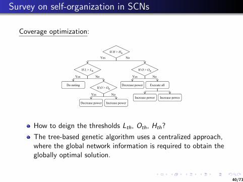
Coverage optimization:
Yes
If L > Lth
If H > Hth
No
If O > Oth
If O > Oth
Do noting
Increase power Increase power
Yes No
Yes No
Execute allDecrease power
Yes No
Decrease power Increase power
p p
How to deign the thresholds Lth, Oth, Hth?
The tree-based genetic algorithm uses a centralized approach,where the global network information is required to obtain theglobally optimal solution.
40/73
Survey on self-organization in SCNs
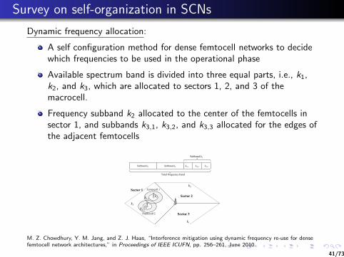
Dynamic frequency allocation:
A self configuration method for dense femtocell networks to decidewhich frequencies to be used in the operational phase
Available spectrum band is divided into three equal parts, i.e., k1,k2, and k3, which are allocated to sectors 1, 2, and 3 of themacrocell.
Frequency subband k2 allocated to the center of the femtocells insector 1, and subbands k3,1, k3,2, and k3,3 allocated for the edges ofthe adjacent femtocells
Subband k3
Subband k1 Subband k2 k3,1 k3,2 k3,3
Total frequency band
k2Femtocell 1
k2k3,1
Sector 1
Sector 2
k1
k3
Femtocell 2
k2k3,3
Sector 3
3
M. Z. Chowdhury, Y. M. Jang, and Z. J. Haas, “Interference mitigation using dynamic frequency re-use for densefemtocell network architectures,” in Proceedings of IEEE ICUFN, pp. 256–261, June 2010.
41/73
Survey on self-organization in SCNs
Distributed and coordinated spectrum assignment:
A distributed method of spectrum allocation for dense femtocells(self configuration)
Dedicated and shared subbands
Coordinated spectrum assignment in two steps: autonomousdedicated subbabnd selection for basic connectivity (phase 1), andcooperative shared subband selection for high data capacity (phase2)
Femtocells periodically exchange information about the interferingfemtocells (interference cell list)
A femto access point selects the subband with the best channelquality and broadcasts a message to the femtocells in theinterference list.
Y. Wu, H. Jiang, and D. Zhang, “A novel coordinated spectrum assignment scheme for densely deployed enterpriseLTE femtocells,” in Proceedings of IEEE VTC Spring, May 2012.
42/73

Survey on self-organization in SCNs
Resource allocation for service differentiation:
A self-configuration and self-optimization framework to provideservice differentiation among different service classes
Femtocells are connected to a femtocell management system(FMS), which collects global network information and performsinterference mitigation among femtocells.
Femtoaccess point
Femtocell management systemWired connection
Interference graph
Y.-S. Liang, W.-H. Chung, G.-K. Ni, I.-Y. Chen, H. Zhang, and S.-Y. Kuo, “Resource allocation with interferenceavoidance in OFDMA femtocell networks,” IEEE Transactions on Vehicular Technology, vol. 61, no. 5, pp.2243–2255, Jun 2012.
43/73
Survey on self-organization in SCNs
Resource allocation for service differentiation:
Initialization phase and resource allocation phase
During the initialization phase, the femtocells collect informationabout their neighbors and report to FMS.
During the resource allocation phase, the FMS performs physicalresource block allocation based on an optimization formulation.
1 Objective: maximize the utilization of the the resource blocks2 Constraints: the same resource block cannot be assigned to
multiple femtocells which have a direct interference link, andutilization ratio for the transmission frame must be less than orequal to one.
3 Rate constraint and L2 packet delay constraint are alsoconsidered.
A binary interference model is used and impact of interference dueto macro users is not considered.
44/73

Survey on self-organization in SCNs
Self-organizing femtocell management architecture:
“Tri-control loop architecture” to protect uplink transmissions atmacrocells and femtocells.
Three control loop components: maximum transmission powercontrol loop (MTXPC), target SINR control loop (TSINRC), andinstantaneous transmission power control loop (ITXPC).
J.-H. Yun and K. G. Shin, “Adaptive interference management of OFDMA femtocells for co-channel deployment,”IEEE Journal on Selected Areas in Communications, vol. 29, no. 6, pp. 1225–1241, June 2011.
45/73

Survey on self-organization in SCNs
Self-organizing femtocell management architecture:
MTXPC determines the maximum transmit power of a femto userbased on the load margin of the macrocell uplink (solution of asteady state tracking problem in control theory).
TSINRC decides the target SINR for femto users using maximumtransmit power (Nash equilibrium solution in a noncooperative gamesetting).
ITXPC allocates the actual transmit power to achieve the targetSINR under the constrained maximum transmit power (solution of acontrol problem).
46/73
Survey on self-organization in SCNs
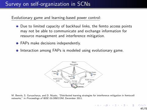
Evolutionary game and learning-based power control:
Due to limited capacity of backhaul links, the femto access pointsmay not be able to communicate and exchange information forresource management and interference mitigation.
FAPs make decisions independently.
Interaction among FAPs is modeled using evolutionary game.
Femtouser
Femtouser
Macro base station
Femto access point
Femto access point
Macro user
Gateway
PayoffAverage payoff Payoff
M. Bennis, S. Guruacharya, and D. Niyato, “Distributed learning strategies for interference mitigation in femtocellnetworks,” in Proceedings of IEEE GLOBECOM, December 2011.
47/73

Survey on self-organization in SCNs
Evolutionary game and learning-based power control:
Reinforcement learning (e.g., Q-learning) can be used for channelaccess and transmission power selection.
Q-learning aims at finding a policy that maximizes the observedrewards (i.e., payoffs) over a certain time period.
Every FAP explores the environment, observes its current state s,and takes a subsequent action a, according to a decision policyπ : s → a, which is a mapping from state s to action a. With theability to learn, knowledge about other FAPs’ strategies is notneeded.
Cooperative Q-learning: Instead of learning by themselves, FAPscan learn from an expert.
A given FAP modifies its Q-values and learns from a small group ofother FAPs that it considers as the expert. The exchange ofinformation between FAPs is performed periodically.
48/73

Survey on self-organization in SCNs
Coordination mechanism for self-organizing femtocells:
FAPs creating co-channel interference to a macro user (“victim”)can use a coordination mechanism (e.g., to reduce transmissionpower, switch to different subband).
Victim user
Coordinating
Femto access point
Coordinating region R1
Coordinating region R2
C. H. M. de Lima, M. Bennis, and M. Latva-aho, “Coordination mechanisms for stand-alone femtocells inself-organizing deployments,” in Proceedings of IEEE GLOBECOM, December 2011.
49/73

Survey on self-organization in SCNs
Coordination mechanism for self-organizing femtocells:
A macro user is identified to be a “victim” user if this userexperiences an aggregate co-channel interference which is higherthan a predefined threshold.
The victim user sends a signaling message to the nearby FAPs (e.g.,in coordinating region R1).
Only the FAPs with strong interference adapt their transmissionparameters.
FAPs in the coordinating region R1 can switch the subband andFAPs in region R2 may also reduce their transmission power.
MacrocellFemtocell
Dedicated frequency band
Macrocell and femtocell
Same frequency band Partial frequency band
Macrocell
Femtocell
50/73

Survey on self-organization in SCNs
Collaborative resource allocation for self-healing femtocells:
A joint self-healing and self optimization scheme
All femtocells periodically transmit a message to the server;message not received −→ failure
Nearby femtocells support the users of the failed femtocell.
Femto user via normal channel
Femto user via normal channel
Macro base station
Macro user
Operation and management
(OAM) serverFemto user via
healing channelFaulty
femtocell
Normal femtocell
Normal femtocell
( ) healing channel
K. Lee, H. Lee, and D.-H. Cho, “Collaborative resource allocation for self-healing in self-organizing networks,” inProceedings of IEEE ICC, June 2011.
51/73

Survey on self-organization in SCNs
Collaborative resource allocation for self-healing femtocells:
KH = set of healing channels, KN = set of normal channels
Selection of the worst subchannel k∗:
k∗ = arg mink∈KN
(Ux(f ,k),k − Ux(f ,−k),−k
Ux(f ,k),k
)(1)
where Ux(f ,k),k = network throughput when the subchannel k isallocated to a user, Ux(f ,−k),−k = network throughput when thesubchannel k is not allocated to a user
Subchannel k∗ is assigned to be the healing channel to the userwith the highest transmission rate in the faulty femtocell, if the gain
g =Ux(f ∗,k∗),k∗ − Ux(f ,k),k
Ux(f ,k),k(2)
is greater than zero. That is, KN = KN \ k∗ and KH = KH ∪ K∗.
52/73
Cognitive spectrum access by small cells
Spectrum sensing range and spectrum reuse efficiency
Spectrum access schemes by cognitive small cells1 Performance gain due to opportunistic spectrum access2 Effect of channel allocation at the macro tier
Clustering-based spectrum access by cognitive small cells
53/73

Spectrum sensing range and spectrum reuse efficiency
Interference is the most performance limiting parameter inHetNets
Infeasible to use traditional centralized techniques tocoordinate spectrum access by a large number of small cells(hence distributed SON)
A cognitive small cell will not access a channel unless thepower received on that channel from any other network entityis less than the spectrum sensing threshold.
Due to the distance-dependent signal power decay, thespectrum sensing threshold defines an area where nointerference source exists.
54/73

Spectrum sensing range and spectrum reuse efficiency
A channel used by a network entity (i.e., an MBS or an SBS)located at x ∈ R2 can be reused by a cognitive SBS locatedat y ∈ R2 if and only if
‖x − y‖ ≥(Ptxh(x , y)
γ
) 1η
(3)
where h(x , y) = random channel gain between the twolocations x and y , Ptx = transmit power of the network entitylocated at x , γ = spectrum sensing threshold, ‖.‖ =Euclidean norm, and η = path-loss exponent.
γ is the design parameter that controls the minimum
frequency reuse distance re =(Ptxh(x ,y)
γ
) 1η
and hence the
spatial reuse efficiency.
55/73
Spectrum sensing range and spectrum reuse efficiency
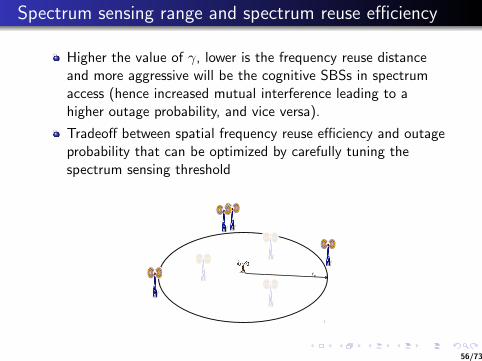
Higher the value of γ, lower is the frequency reuse distanceand more aggressive will be the cognitive SBSs in spectrumaccess (hence increased mutual interference leading to ahigher outage probability, and vice versa).
Tradeoff between spatial frequency reuse efficiency and outageprobability that can be optimized by carefully tuning thespectrum sensing threshold
!"#
$#
56/73
Spectrum access schemes by cognitive small cells
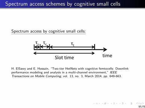
Spectrum access by cognitive small cells:
!"
#$%&"&'()"
*" &"
&'()"
H. ElSawy and E. Hossain, “Two-tier HetNets with cognitive femtocells: Downlinkperformance modeling and analysis in a multi-channel environment,” IEEETransactions on Mobile Computing, vol. 13, no. 3, March 2014, pp. 649-663.
57/73
Spectrum access schemes by cognitive small cells
A cognitive small cell will not access a channel which is beingused by nearby macocell and small cells.
Unavailability of radio channels may lead to outage.
Each time slot is divided into three main parts (scheme-1).
1 First part: each cognitive small cell senses the availablespectrum to detect the channels which are not used by theMBS.
2 Second part: each cognitive small cell contends to access oneof the available channels (e.g., using a random backoff processwhile persistently sensing the channel).
3 Third part: if the sensed channel was available during theentire backoff duration (i.e., not used by a nearby small cell),the cognitive small cell transmits on that channel for the restof the time slot. Otherwise, the small cell is considered to bein outage due to channel unavailability.
58/73

Spectrum access schemes by cognitive small cells
Due to the unified sensing threshold γ each cognitive SBS (e.g.,FAP) will have two spectrum sensing regions (SSR).
1 macro SSR2 femto SSR
A cognitive SBS (e.g., FAP) should avoid using any channel used bya macro BS in the macro SSR and any channel used by any FAP inthe femto SSR.
rsa
rsb
59/73

Spectrum access schemes by cognitive small cells
For downlink transmission, total outage probability for a smallcell user can be expressed as
Pout = (1− P{opportunistic access}) +
P{SINR ≤ β} P{opportunistic access}
where SINR is the signal-to-interference-plus-noise ratio and βis the threshold defined for correct signal reception.
Both the opportunistic spectrum access probability and theSINR outage depend on the network geometry.
60/73
Spectrum access schemes by cognitive small cells
Outage could be due to channel unavailability foropportunistic access and/or due to SINR violation (i.e.,resulting from aggregate interference).
Spectrum sensing threshold controls the tradeoff between thetwo outages.
Increasing the spectrum sensing threshold decreases thefrequency reuse distance and increases the opportunisticchannel access, however, it increases the aggregateinterference and hence the SINR outage.
61/73
Spectrum access schemes by cognitive small cells
For a given spectrum sensing threshold, since theopportunistic spectrum access performance of the small cellswill deteriorate when the intensity of the deployed small cellsis high, introducing spectrum awareness at a small cell withrespect to the spectrum usage at the other small cells may notbe the best solution.
Instead, cognition can be introduced only with respect to themacro-tier. That is, each SBS senses the spectrum to locatethe channels which are not used by the MBS and uses any ofthem without considering the other SBSs (scheme-2).
62/73

Spectrum access schemes by cognitive small cells
Each time slot is divided into two main parts (scheme-2).1 First part: each cognitive small cell senses the available
spectrum to detect the channels which are not used by themacrocell.
2 Second part: each cognitive small cell selects one of theavailable channels and transmits in that channel.
Channels will be aggressively used in the small cell tier toincrease their opportunistic spectrum access performance atthe expense of higher mutual interference in the small cell tier.
63/73

Spectrum access schemes by cognitive small cells
Performance gain due to cognitive spectrum access:
Outage probability (of small cell users) vs. spectrum sensingthreshold for cognitive techniques and different values pc (=percentage of SBSs operating in the closed access mode)
Outage due to SINR violation and outage due to unavailability ofchannel for opportunistic spectrum access for small cell users vs.spectrum sensing threshold for different cognitive techniques anddifferent values pc
−100 −80 −60 −40 −20 0 20 400.1
0.2
0.3
0.4
0.5
0.6
0.7
0.8
0.9
1
Spectrum sensing threshold (dBm)
Out
age
prob
abili
ty
NC−FAP, pc=0.9
FC−FAP, pc=0.9
SC−FAP, pc=0.9
NC−FAP, pc=0.5
FC−FAP, pc=0.5
SC−FAP, pc=0.5
NC−FAP, pc=0.1
FC−FAP, pc=0.1
SC−FAP, pc=0.1
pc=0.9
pc=0.5
pc=0.1
−100 −80 −60 −40 −20 0 20 4010−6
10−5
10−4
10−3
10−2
10−1
100
Spectrum sensing threshold (dBm)
Out
age
prob
abili
ty
SC−FAP, pc=0.9SC−FAP, pc=0.5
SC−FAP, pc=0.1
FC−FAP, pc=0.9FC−FAP, pc=0.5
FC−FAP, pc=0.1
FC−FAP outage due to opprtunistic spectrum accessSC−FAP outage due to opprtunistic spectrum access
Outage due to opportunistic access
FC−FAP SINR outage
SC−FAP SINR outage
64/73
Spectrum access schemes by cognitive small cells
There exists an optimal spectrum sensing threshold thatdepends on the network parameters and the cognitiontechnique.
A higher value of spectrum sensing threshold results in shorterfrequency reuse distances and more spectrum opportunities,however, the aggregate interference increases and dominatesthe outage probability. This results in a degraded outageperformance.
For very high values of spectrum sensing threshold, thecognitive small cells become very aggressive and theirperformance matches with that of the non-cognitive smallcells.
Lower values of spectrum sensing threshold result in higherfrequency reuse distance and lower aggregate interference;however, the opportunistic spectrum access probabilitydecreases and dominates the outage probability.
65/73
Spectrum access schemes by cognitive small cells
Summary of observations:
For scheme-1, the decreased SINR outage probability iswasted by the outage probability due to the channelunavailability.
The degraded SINR outage probability of scheme-2 isbalanced by the improved spectrum access probability.
Cognition is an important feature that can significantlyenhance the HetNet performance.
Introducing cognition w.r.t. the macro-tier only is morebeneficial than introducing cognition w.r.t. the two networktiers (due to uncoordinated access among densely deployedcoexisting small cells).
66/73

Spectrum access schemes by cognitive small cells
Effect of channel allocation at the macro tier:
Two channel assignment techniques for the MBSs in in a two-tiernetwork with cognitive SBSs: random channel assignment (RCA)and sequential channel assignment (SCA)
RCA: each MBS randomly and uniformly chooses one channel foreach of its associated users
SCA: the available channels have a specific order and each MBSassigns the channels to its associated users in a sequential manner.
RCA deteriorates the opportunistic spectrum access performance forcognitive SBSs.
SCA minimizes the number of unique channels used by thecoexisting MBSs (hence maximizes the opportunistic spectrumaccess performance for cognitive SBSs)
67/73

Spectrum access schemes by cognitive small cells
Channels available to a cognitive SBS for opportunistic access:
9 channels
1 channel
3 channel
9 channels or more
68/73

Spectrum access schemes by cognitive small cells
Effect of channel allocation at the macro tier:
SINR performance for macro users
−100 −95 −90 −85 −80 −75 −70 −65 −60 −55 −500.1
0.2
0.3
0.4
0.5
0.6
0.7
0.8
γ (dBm)
Mac
ro u
ser c
over
age
prob
abilit
y
Non−cognitive, RCANon−cognitive,SCACognitive, RCACognitive, scheme 2
Cognitive
Non−cognitive
−10 −8 −6 −4 −2 0 2 4 6 8 100
0.1
0.2
0.3
0.4
0.5
0.6
0.7
0.8
0.9
1
β (dB)
Mac
ro u
ser c
over
age
prob
abilit
y
Non−cognitive, RCANon−cognitive, SCACognitive, RCACognitive, SCA
Non−cognitive
Cognitive
69/73

Spectrum access schemes by cognitive small cells
Opportunistic spectrum access for small cells
0 5 10 15 20 25 300
0.05
0.1
0.15
0.2
0.25
0.3
0.35
Number of channel available for opportunistic access
Prob
abilit
y
RCASCA
−100 −95 −90 −85 −80 −75 −70 −65 −60 −55 −500
0.1
0.2
0.3
0.4
0.5
0.6
0.7
0.8
0.9
1
γ (dBm)
Prob
abilit
y(C fre
e ≥ n
)
n=1, RCAn=1, SCAn=5, RCAn=5, SCAn=10, RCAn=10, SCA
SCA
RCA
70/73

Clustering-based spectrum access by cognitive small cells
The concept of clustering may be used to optimize thetradeoff between the outage due to opportunistic spectrumaccess and outage due to the aggregate interference.
In clustering, adjacent small cells group together and elect acluster head to coordinate the spectrum access within thecluster.
Many challenges need to be addressed to implementclustering.
1 What is the optimal cluster size2 What information is to be exchanged among the cluster
members3 How to elect the cluster head4 What is the allocation strategy that maximizes the throughput
in the small cells while maintaining fairness among the clustermembers.
71/73
Future research directions
Self-organization in presence of multiple radio accesstechnology (multi-RAT) and inter-RAT cooperation (e.g., LTEand Wi-Fi integration)
Self-organization by exploiting carrier aggregation in bothaccess and backhaul links
Backhaul-aware self-organization
Context-aware self-organization
Self-organization for energy efficiency
Self-organization of small cell networks in the TV band
Reliability analysis and redundancy design for self-organizingsmall cell networks
Security issues in the self-organization of small cells
72/73
Book on small cell networks
73/73