Self-healing concrete with a microencapsulated …energetics.chm.uri.edu/system/files/Self healing...
21
Self-healing concrete with a microencapsulated healing agent Michelle M. Pelletier, 1,2 Richard Brown 2 , Arun Shukla 3 and Arijit Bose 1,2 1 Laboratory of Soft Colloids & Interfaces, 2 Department of Chemical Engineering 3 Dynamic Photomechanics Laboratory, Department of Mechanical, Industrial and Systems Engineering University of Rhode Island, Kingston, RI, 02881, USA MMP:[email protected] , RB: [email protected] , AS: [email protected] , AB: [email protected] Corresponding Author: Arijit Bose Phone: +1-401-874-2804 Fax: +1-401-874-4689 Email address: [email protected] Keywords: Calcium-silica-hydrate (C-S-H) (B), Microcracking (B), Corrosion (C), Mechanical Properties (C), Self-healing
Transcript of Self-healing concrete with a microencapsulated …energetics.chm.uri.edu/system/files/Self healing...
Self-healing concrete with a microencapsulated healing agent
Michelle M. Pelletier,1,2 Richard Brown 2, Arun Shukla 3 and Arijit Bose 1,2 1Laboratory of Soft Colloids & Interfaces, 2Department of Chemical Engineering
3Dynamic Photomechanics Laboratory, Department of Mechanical, Industrial and Systems Engineering
University of Rhode Island, Kingston, RI, 02881, USA
MMP:[email protected], RB: [email protected], AS: [email protected], AB: [email protected] Corresponding Author: Arijit Bose Phone: +1-401-874-2804 Fax: +1-401-874-4689 Email address: [email protected] Keywords: Calcium-silica-hydrate (C-S-H) (B), Microcracking (B), Corrosion (C), Mechanical
Properties (C), Self-healing
Abstract
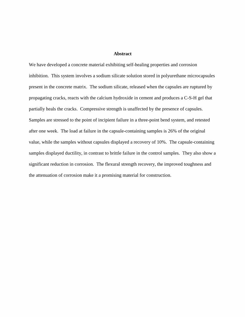
We have developed a concrete material exhibiting self-healing properties and corrosion
inhibition. This system involves a sodium silicate solution stored in polyurethane microcapsules
present in the concrete matrix. The sodium silicate, released when the capsules are ruptured by
propagating cracks, reacts with the calcium hydroxide in cement and produces a C-S-H gel that
partially heals the cracks. Compressive strength is unaffected by the presence of capsules.
Samples are stressed to the point of incipient failure in a three-point bend system, and retested
after one week. The load at failure in the capsule-containing samples is 26% of the original
value, while the samples without capsules displayed a recovery of 10%. The capsule-containing
samples displayed ductility, in contrast to brittle failure in the control samples. They also show a
significant reduction in corrosion. The flexural strength recovery, the improved toughness and
the attenuation of corrosion make it a promising material for construction.
1. Introduction
Concrete is the most commonly used building material in the world. It is strong, durable, locally
available and versatile. It is an inexpensive material to produce and is recyclable. Unfortunately,
concrete is susceptible to many sources of damage. Cracks can form at any stage of its life and
most begin internally where they cannot be seen for years until major repairs are needed.
Damage is caused by freeze/thaw cycles, corrosion, extreme loads, chemical attacks and other
environmental conditions. Consequently, maintenance to concrete structures is frequent and
costly. Billions of dollars are spent every year on buildings, bridges and highways for
maintenance, making materials requiring less frequent repairs very appealing [1]. The production
of concrete is an energy-intensive process when mining, transportation and processing is
considered. Its production level lies at about 2.35 billion metric tons per year and contributes an
astonishing 10% of CO2 emissions into the atmosphere [2].
Damage, deterioration and overall structural integrity are conventionally monitored through
routine inspections and repair. This may involve surface repairs, admixtures, sealant
applications, surface washing and corrosion monitoring. In the past decade, the building industry
has taken a significant interest in engineering concrete as a smart material to alleviate issues such
as excessive routine maintenance, excessive production and costs. One strategy to do this would
be to mitigate microscale damage through an autonomous method that senses and repairs cracks
in a targeted way. An example is a material that requires a heating device to melt small, film-
like pipes that are embedded into the concrete when cracks occur [3-5]. Similarly, Mihashi and
Yoshio proposed incorporating glass pipes containing the repairing agent into the concrete for
self-healing capabilities to restore strength and for the prevention of water leakage [6]. This
concept was also utilized by Li et al. who incorporated hollow glass fibers containing ethyl
cyanoacrylate, a thermoplastic monomer, into the mix [7]. This filled hollow-fiber method has
been successful in other concrete systems as well as reinforced polymers and epoxies [8-14], but
limitations such as a lack of ease in manufacturing have made these products undesirable for
commercial use.
Sottos et al. have developed a polymer composite system that incorporates a catalyst into the
polymer matrix phase with a microencapsulated repair agent [15]. The healing agent is released
upon crack propagation through the microcapsule, resulting in as much as an 80% recovery of
toughness after a fracture. This method has been successfully demonstrated in various polymer
composite systems [16-18].
The material presented here involves a microencapsulated healing agent that utilizes stress as a
trigger for self-healing to occur. Polyurethane microcapsules with an aqueous sodium silicate
core are contained within the concrete matrix at 2% volume. When a mechanical stress is
applied, the capsules rupture and release sodium silicate into the adjacent cracks (Figure 1) [19].
The sodium silicate reacts with calcium hydroxide, a product of cement hydration, and produces
a calcium-silica-hydrate (C-S-H) gel – a binding material natural to concrete. The C-S-H gel (x.
(CaO.SiO2).H2O) partially fills the crack, and allows some recovery of strength. The relevant
chemical reactions are shown below:
Na2O • SiO2 + Ca(OH)2 x(CaO • SiO2) • H20 + Na2O
x(CaO • SiO2)• H20 + Na2O + CO2 CaCO3 + SiO2 + 2NaOH
C-S-H is a complex product that often has varying C/S ratios present and may differ slightly in
nanostructure. It has been observed in hydrated cement and is described as a network of
nanoparticles [20]. For this application, only the first reaction is considered because the product
forms rapidly. It is the newly formed C-S-H gel that will act as a binder and healer in cracks and
pores, bridging the gaps in the material and ultimatley improving its strength. The second
reaction is based on a much longer time scale (years). Sodium-silica-hydrate (N-S-H) is
observed in concrete as a result of the reaction between sodium hydroxide and silica [21]. N-S-
H is thought to be analogous to C-S-H but has not been well characterized. Thus, the long-term
products initiated by the presence of sodium silicatewill still be helpful to the integrity of the
concrete.
Corrosion inhibition was also explored. When stressed, the healing agent is released and some
of the sodium silicate deposits on the metal reinforcement bars (rebars) traditionally used in
concrete. The formation of a passive film on the surface of the metal will protect it from
corrosion. Additionally, reduced water transport through the concrete matrix due to reduced
porosity, decreased interconnectivity and healed cracks will slow down the ingress of damaging
chlorides, ultimately inhibiting the rebar corrosion rate.
In experiments in our laboratory, sodium silicate was added to the concrete mix to test its ability
to retard water ingress and impact on compressive strength. Its addition showed significant
decreases in the water absorption rate and the overall porosity along with increases in the
compressive strength [22]. These results motivated the microencapsulation of the sodium
silicate solution to demonstrate targeted self-healing behavior.
2. Materials and Methods
2.1 Sample Preparation
2.1.1 Polyurethane microcapsule synthesis
The in situ synthesis using an interfacial polymerization adapted from Saihi et al. is described in
the following steps [23]. 4.202mL of Span 85 and 2.116mL of polyethyleneglycol (PEG) were
dissolved in 90mL of toluene. A 15mL aliquot was taken from this solution and placed into a
separate beaker (referred to as E1). 0.682mL of methylene diiosocyanate (Basonat) and
0.0469mL of dibutyl tin dilaureate was dissolved in E1. This blend was mixed at 350 rpm to
ensure a homogenous mixture and set aside. The original mixture (Span 85, PEG and toluene)
was combined with 30mL of water, stirring at 8000rpm in a homogenizer or blender. Finally, E1
was added to this primary emulsion and stirred at 700rpm for 10 minutes at room temperature.
The speed was reduced to 350 rpm at 63ºC and allowed to react for 4 hours. An optical
microscope image of a polyurethane microcapsule is shown in Figure 2. Microcapsules sizes
varied from 40-800 microns.
2.1.2 Concrete samples
All samples are prepared to the specifications of ASTM C-109 with a mix containing 1375
grams of Ottawa C-109 sand, 500 grams of Type I/II Portland cement and 242 mL of water. For
samples containing the polyurethane microcapsules, the capsules were added to the mix water at
2% volume and prepared identical to the control samples. Molds of dimensions 160mm x 40mm
x 20mm (for flexural strength) and 500mm x 500mm x 500mm (for compressive strength) were
used. After being stripped from the molds, the specimens were submerged in water for two days
then contained in a 95% constant humidity environment for 28 days to ensure full curing.
2.2 Crack formation
For mechanical strength test, randomized internal microscale damage was induced with an
applied load to incipient failure, to mimic realistic cracking patterns. For the corrosion testing,
one large crack was induced directly to the iron wire to ensure a common path between samples.
2.2.1 Flexural strengths
For the flexural strength tests, the 160mm x 40mm x 20mm samples were used. Each sample
was subjected to an applied load of 0.25 mm/min to induce microcracking within the sample.
The cracking is minor and internal only and meant to mimic microscale damage and
deformations that occur within the concrete after applied or natural stress, and prior to
catastrophic failure. After one week, these samples were retested to see how much strength has
been recovered after the initial damage.
2.2.2 Corrosion
For the corrosion experiments, a larger, single crack was induced to give the sodium chloride
solution a direct and common path to the iron wire in each sample. This was achieved by
subjecting the 160mm x 40mm x 20mm samples to a three point bend test so that a crack
propagated directly to the wire upon failure. An example of a sample with a crack is shown in
Figure 3.
2.3 Experimental Methods
2.3.1 Compressive strength tests
The experimental procedure to determine the compressive strength of each specimen is adapted
from ASTM C109 [24]. Each sample is centered between the two parallel discs. The strain rate
is 1 mm/min. For the first test, the load is stopped after the sample has reached a maximum load
and shows a gradual descent, but is not allowed to reach failure. After the healing time has
passed, each sample is retested to failure. We report the results of the retested samples only.
2.3.2 Flexural strength tests
The experimental procedure to determine the flexural strength of each specimen is adapted from
ASTM C348-97 [25]. The flexural strength is measured by means of a three point bend test.
Samples are supported by two parallel beams and compressed by one central beam. The load is
set to move at 0.25 mm/min. For the first test, the load is stopped after the sample has reached a
maximum load and shows a sharp descent, but is not allowed to reach failure. After the healing
time has passed, each sample is retested to failure.
2.3.3 Corrosion monitoring
A 0.5M solution of sodium chloride was used to represent the ingress of chlorides to the steel
reinforcement bars in concrete. An acrylic well was adhered to the surface of each rectangular
sample with 3M 5200 Adhesive Sealant to ensure a tight, waterproof seal . The cylindrical well
is 3 centimeters in diameter and is located directly over the wire present at the center of each
sample. The bottom face opposite the well was fixed with a piece of Parafilm and all other
surfaces were sealed with duct tape. A piece of sandpaper was used to sand off any rust or
impurities that may have built up on the iron wire during curing and to ensure a good connection
of the voltmeter to the wire. A potassium chloride reference electrode was placed in the empty
well. The sodium chloride was poured into the small well and allowed to travel through the
pores and crack to reach the iron wire. The voltage of the wire was recorded over time until the
wire was corroded internally.
3. Results and Discussion
3.1 Compressive strength
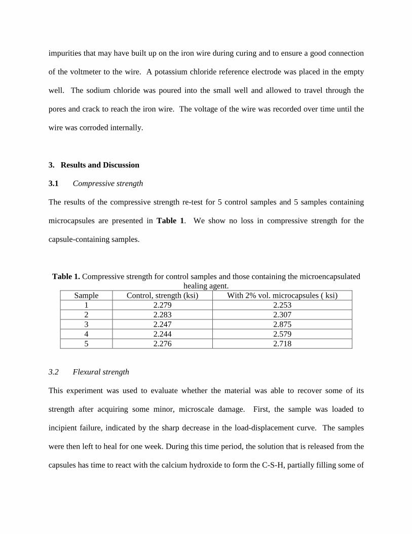
The results of the compressive strength re-test for 5 control samples and 5 samples containing
microcapsules are presented in Table 1. We show no loss in compressive strength for the
capsule-containing samples.
Table 1. Compressive strength for control samples and those containing the microencapsulated healing agent.
Sample Control, strength (ksi) With 2% vol. microcapsules ( ksi) 1 2.279 2.253 2 2.283 2.307 3 2.247 2.875 4 2.244 2.579 5 2.276 2.718
3.2 Flexural strength
This experiment was used to evaluate whether the material was able to recover some of its
strength after acquiring some minor, microscale damage. First, the sample was loaded to
incipient failure, indicated by the sharp decrease in the load-displacement curve. The samples
were then left to heal for one week. During this time period, the solution that is released from the
capsules has time to react with the calcium hydroxide to form the C-S-H, partially filling some of
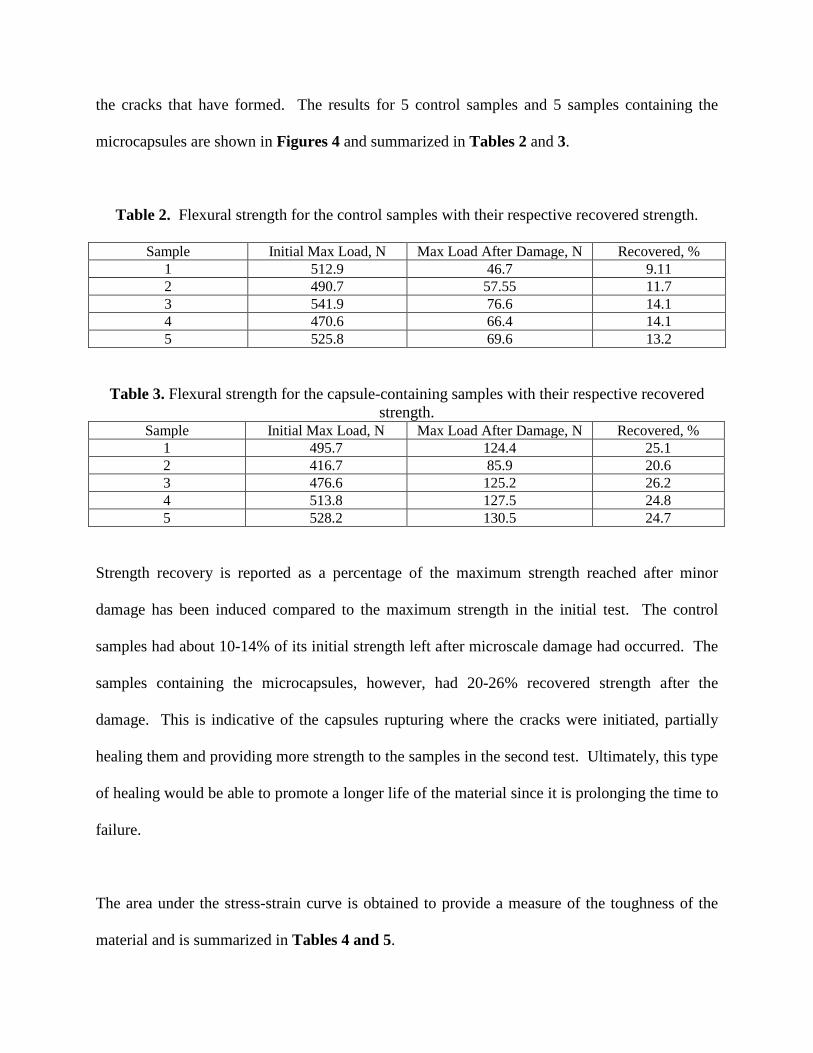
the cracks that have formed. The results for 5 control samples and 5 samples containing the
microcapsules are shown in Figures 4 and summarized in Tables 2 and 3.
Table 2. Flexural strength for the control samples with their respective recovered strength.
Sample Initial Max Load, N Max Load After Damage, N Recovered, % 1 512.9 46.7 9.11 2 490.7 57.55 11.7 3 541.9 76.6 14.1 4 470.6 66.4 14.1 5 525.8 69.6 13.2
Table 3. Flexural strength for the capsule-containing samples with their respective recovered strength.
Sample Initial Max Load, N Max Load After Damage, N Recovered, % 1 495.7 124.4 25.1 2 416.7 85.9 20.6 3 476.6 125.2 26.2 4 513.8 127.5 24.8 5 528.2 130.5 24.7
Strength recovery is reported as a percentage of the maximum strength reached after minor
damage has been induced compared to the maximum strength in the initial test. The control
samples had about 10-14% of its initial strength left after microscale damage had occurred. The
samples containing the microcapsules, however, had 20-26% recovered strength after the
damage. This is indicative of the capsules rupturing where the cracks were initiated, partially
healing them and providing more strength to the samples in the second test. Ultimately, this type
of healing would be able to promote a longer life of the material since it is prolonging the time to
failure.
The area under the stress-strain curve is obtained to provide a measure of the toughness of the
material and is summarized in Tables 4 and 5.
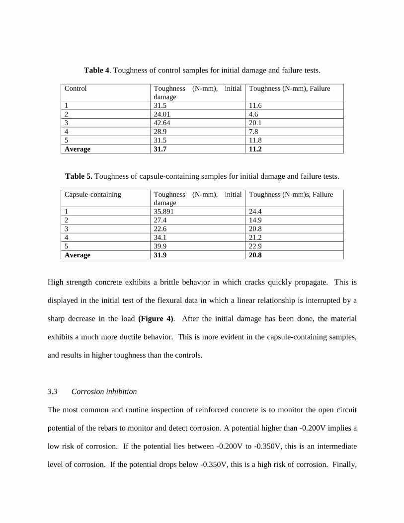
Table 4. Toughness of control samples for initial damage and failure tests.
Control Toughness (N-mm), initial damage
Toughness (N-mm), Failure
1 31.5 11.6 2 24.01 4.6 3 42.64 20.1 4 28.9 7.8 5 31.5 11.8 Average 31.7 11.2
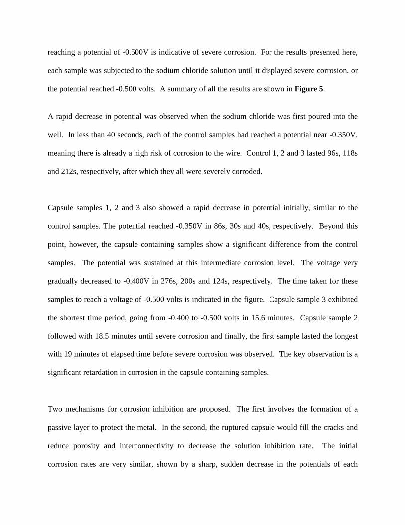
Table 5. Toughness of capsule-containing samples for initial damage and failure tests.
Capsule-containing Toughness (N-mm), initial damage
Toughness (N-mm)s, Failure
1 35.891 24.4 2 27.4 14.9 3 22.6 20.8 4 34.1 21.2 5 39.9 22.9 Average 31.9 20.8
High strength concrete exhibits a brittle behavior in which cracks quickly propagate. This is
displayed in the initial test of the flexural data in which a linear relationship is interrupted by a
sharp decrease in the load (Figure 4). After the initial damage has been done, the material
exhibits a much more ductile behavior. This is more evident in the capsule-containing samples,
and results in higher toughness than the controls.
3.3 Corrosion inhibition
The most common and routine inspection of reinforced concrete is to monitor the open circuit
potential of the rebars to monitor and detect corrosion. A potential higher than -0.200V implies a
low risk of corrosion. If the potential lies between -0.200V to -0.350V, this is an intermediate
level of corrosion. If the potential drops below -0.350V, this is a high risk of corrosion. Finally,
reaching a potential of -0.500V is indicative of severe corrosion. For the results presented here,
each sample was subjected to the sodium chloride solution until it displayed severe corrosion, or
the potential reached -0.500 volts. A summary of all the results are shown in Figure 5.
A rapid decrease in potential was observed when the sodium chloride was first poured into the
well. In less than 40 seconds, each of the control samples had reached a potential near -0.350V,
meaning there is already a high risk of corrosion to the wire. Control 1, 2 and 3 lasted 96s, 118s
and 212s, respectively, after which they all were severely corroded.
Capsule samples 1, 2 and 3 also showed a rapid decrease in potential initially, similar to the
control samples. The potential reached -0.350V in 86s, 30s and 40s, respectively. Beyond this
point, however, the capsule containing samples show a significant difference from the control
samples. The potential was sustained at this intermediate corrosion level. The voltage very
gradually decreased to -0.400V in 276s, 200s and 124s, respectively. The time taken for these
samples to reach a voltage of -0.500 volts is indicated in the figure. Capsule sample 3 exhibited
the shortest time period, going from -0.400 to -0.500 volts in 15.6 minutes. Capsule sample 2
followed with 18.5 minutes until severe corrosion and finally, the first sample lasted the longest
with 19 minutes of elapsed time before severe corrosion was observed. The key observation is a
significant retardation in corrosion in the capsule containing samples.
Two mechanisms for corrosion inhibition are proposed. The first involves the formation of a
passive layer to protect the metal. In the second, the ruptured capsule would fill the cracks and
reduce porosity and interconnectivity to decrease the solution inbibition rate. The initial
corrosion rates are very similar, shown by a sharp, sudden decrease in the potentials of each
sample. The control samples exhibit uniform corrosion. The chlorides permeate through the
concrete quickly and severe corrosion is observed. The capsule-containing samples have this
interesting point where they are able to sustain the intermediate potential. One proposed
hypothesis is that its behavior is a combination of both the healing properties and passive layer,
but more dependent on the latter. First, there is probably a presence of a thin passive layer that
formed from the effects of the ruptured capsules. This passive layer, however, is probably not
uniform over the entire wire. The chlorides moved quickly through the path of least resistance,
which is the large, induced crack directly to the wire, and affect any of those areas not protected
by the passive film. These areas are easily corroded, explaining the similarity in the initial
corrosion rate and potentials. With some passive layer present, however, it takes the chlorides
longer to have a similar affect on the wire compared to the control samples, which explains why
the time taken for the potential to reach the intermediate level of corrosion at -0.350 volts is
longer. From here on, the mechanism is unclear. Perhaps the solution caused some unreacted
silicates to be transported down to the wire as well which gradually added to the passive layer,
protecting spotty areas along the wire and assisting with corrosion inhibition. Also, it is possible
that the wire directly accessible through the crack is protected by the silicates, forcing the
chloride solution to find a different path to the wire. This would slow the corrosion rate as it
makes it ways through the pores to find the susceptible areas. Finally, after a prolonged period
of time, the passive layer will begin to break down with the overwhelming chloride
concentration, leading to severe corrosion.
4. Conclusions
The microcapsules proved to be an effective way of encapsulating the healing agent for a
targeted release. The results from the compressive strength tests show that the capsules do not
interfere with the cementitious matrix. Their real ability is demonstrated in testing the flexural
strength after inducing microcracks, where the presence of the microcapsules helps the material
perform at least 10% better then the control samples.
The results for the capsule-containing samples showed a significant amount of corrosion
inhibition compared to the control samples. With increased capsule loading (optimized for
strength), more silicates can be deposited onto the wire to form a passive layer that could protect
it for greater time. An ideal application for this system would be as an added aid for corrosion
inhibition in an already protected structure.
5. Acknowledgements
This work was supported by grants from the RI Department of Transportation, the URI
Transportation Center, the Department of Homeland Security and by the NSF (CBET 0730392,
0854115). We acknowledge several fruitful discussions with Michael F. Bräu (BASF).
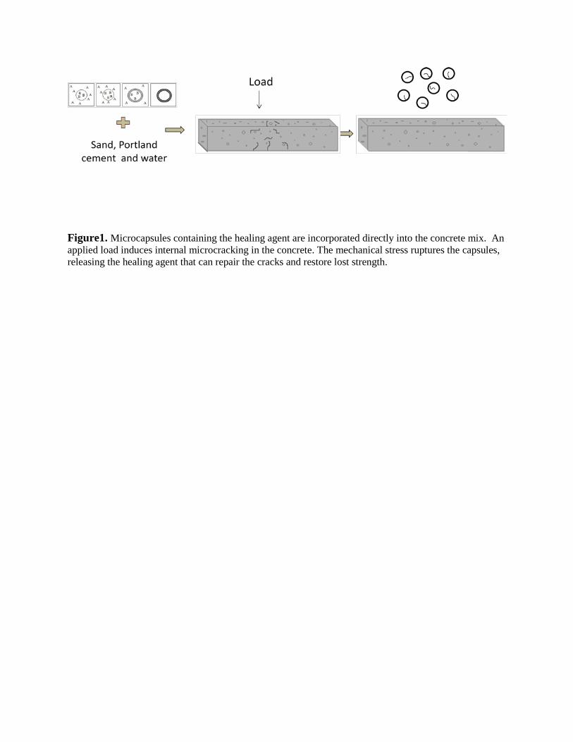
Figure1. Microcapsules containing the healing agent are incorporated directly into the concrete mix. An applied load induces internal microcracking in the concrete. The mechanical stress ruptures the capsules, releasing the healing agent that can repair the cracks and restore lost strength.
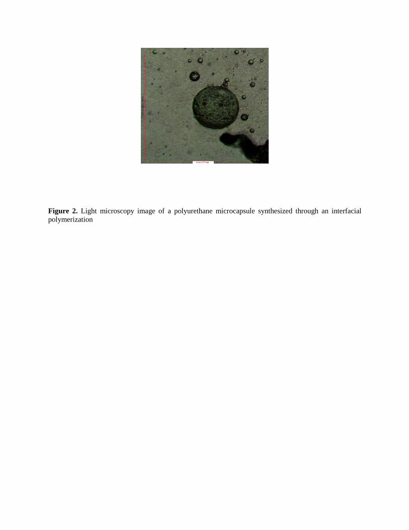
Figure 2. Light microscopy image of a polyurethane microcapsule synthesized through an interfacial polymerization
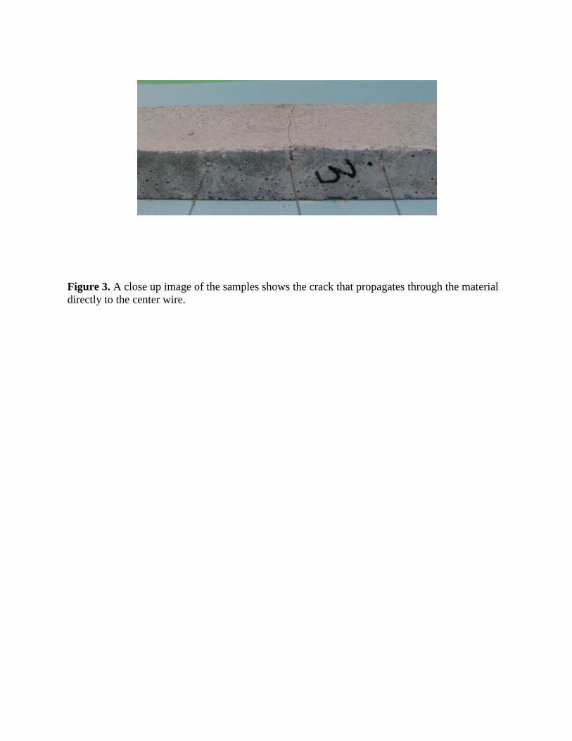
Figure 3. A close up image of the samples shows the crack that propagates through the material directly to the center wire.
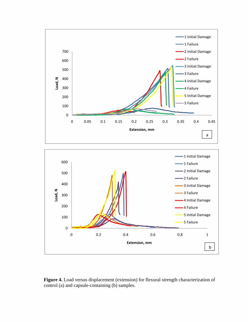
Figure 4. Load versus displacement (extension) for flexural strength characterization of control (a) and capsule-containing (b) samples.
0
100
200
300
400
500
600
700
0 0.05 0.1 0.15 0.2 0.25 0.3 0.35 0.4 0.45
Load
, N
Extension, mm
1 Initial Damage
1 Failure
2 Initial Damage
2 Failure
3 Initial Damage
3 Failure
4 Initial Damage
4 Failure
5 Initial Damage
5 Failure
0
100
200
300
400
500
600
0 0.2 0.4 0.6 0.8 1
Load
, N
Extension, mm
1 Initial Damage
1 Failure
2 Initial Damage
2 Failure
3 Initial Damage
3 Failure
4 Initial Damage
4 Failure
5 Initial Damage
5 Failure
a
b
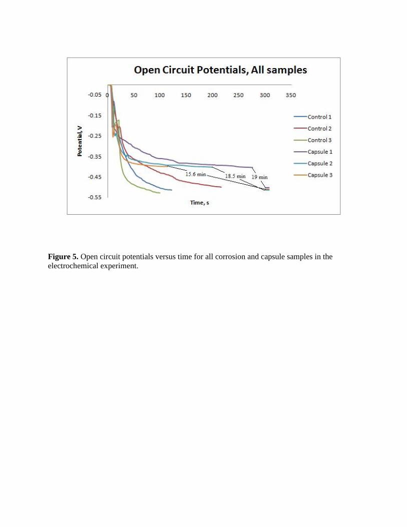
Figure 5. Open circuit potentials versus time for all corrosion and capsule samples in the electrochemical experiment.
REFERENCES
1. FHWA-RD-01-156, Corrosion cost and preventive strategies in the United States. September 2001, CC Technologies Labortories, Inc. to Federal Highway Administration (FHWA), Office of Infrastructure and Development.
2. Jeffries, A. Is it Green? Concrete. 2007 February 5, 2009 [cited 2010 January 21]; [CO2 impact on the earth from concrete production]. Available from: www.inhabitat.com/2009/02/05/is-it-green-concrete/.
3. Nishiwaki, T.e.a., Development of self-healing system for concrete with selective heating around crack. . Journal of Advanced Concrete Technology, 2006. 4(2): p. 267-275.
4. Nishiwaki, T., et al., Thermal Analysis of self-healing concrete system. Konkurito Ronbunshu, 2009. 59: p. 469-476.
5. Nishiwaki, T., et al., Development of self-healing concrete with heating device. Konkurito Ronbunshu, 2005. 16(2): p. 81-88.
6. Mihashi, H. and Y. Kaneko, Intelligent concrete with self-healing capability. Transactions of the Materials Research Society of Japan, 2000. 25(2): p. 557-560.
7. Li, V.C., Y.M. Lim, and Y.-W. Chan, Feasibility study of a passive smart self-healing cementitious composite. Composites Part B, 1998. 29B: p. 819-827.
8. Pang, J.W.C. and I.P. Bond, A hollow fibre reinforced polymer composite ecompassing self-healing and enhanced damage visibility. composites Science and Technology, 2005. 65: p. 1791-1799.
9. Dry, C.M., Alteration of matrix permeability and associated pore and crack structure by timed release of internal chemicals. Ceramic Transactions, 1991: p. 191-193.
10. Dry, C.M., Passive tunable fibers matrices. . International Journal of Modern Physics, 1992. 6: p. 2763-2771.
11. Dry, C.M. Smart building materials which prevent damage or repair themselves. in Proceedings of the Materials Research Society Symposium. 1992. California: Materials Research Society.
12. Dry, C.M. Smart materials which sense, activate and repair damage; hollow porous fibers in composites release chemicals from fibers for self-healing, damage prevention, and/or dynamic control. in First European conference on smart structures and materials. 1992. Glasgow, Scotland.
13. Williams, G., R. Trask, and I.P. Bond, A self-healing carbon fibre reinforced polymer for aerospace applications. Composites Part A, 2007. 38(1525-1532).
14. Williams, G., R. Trask, and I.P. Bond, Bioinspired self-healing of advanced composite strcutres using glass fibres. Journal of the Royal Society Interface, 2007. 4: p. 363-371.
15. Sottos, N.R., M.R. Kessler, and S.R. White, Self-healing structural composite materials. Composites Part A: Applied Science and Manufacturing, 2004. 34(8): p. 743-753.
16. Yin Tao, e.a., Self-healing woven glass fabric/epoxy composites with the healant consisting of micro-encapsulated epoxy and latent curing agent. Smart Material Structures, 2008. 17: p. 15-19.
17. Brown, E.N., N.R. Sottos, and S.R. White, Retardation and repair of fatigue cracks in a microcapsule toughened epoxy composite- Part II: In situ self-healing Composites Science and Technology, 2005. 65(15-16): p. 2474-2480.
18. Yin, T., et al., Self-healing epoxy composites- Preparation and effect of the healant consisting of microencapsulated epoxy and latent curing agent. . Composites Science and Technology 2007. 67(2): p. 201-212.
19. Yow, H.N. and F.A. Routh, Formation of liquid core-polymer shell microcapsules. Soft Matter, 2006. 2: p. 940-949.
20. Nonat, A., Structure and Stoichiometry of C-S-H. Cement and Concrete Research, 2004. 34(9).
21. Kendrick, D.A., J.R. Parsonage, and R. Vazifdar, Interaction of alkali and alkali earth metal hydroxides with microsilica. Cement and Concrete Research, 1998. 28(11): p. 1537-1544.
22. Pelletier, M., Self-Healing Concrete, in Department of Chemical Engineering. 2010, University of Rhode Island: Kingston.
23. Saihi, D., et al., Microencapsulation of ammonium phosphate with a polyurethane shell. Part II. Interfacial polymerization technique. Reacive and Funcitonal Polymers, 2006. 66(10): p. 1118-1125.
24. Allen, R.F., et al., eds. Annual Book of ASTM Standards. Cement: Lime: Gypsum. Vol. 04.01. 1998, American Society for Testing and Materials: West Conshohocken, PA. 71-75.
25. Allen, R.F., et al., eds. Annual Book of ASTM Standards. Cement: Lime: Gypsum. Vol. 04.01. 1998, American Society for Testing and Materials: West Conshohocken, PA. 203-207.