Self-Contained Carpet Extractor · This Thermax self-contained extractor must be properly grounded....
14
WARNING: OPERATOR MUST READ AND UNDERSTAND THIS MANUAL COMPLETELY BEFORE OPERATING THIS EQUIPMENT. Self-Contained Carpet Extractor OPERATORS MANUAL AND PARTS LIST 98150-THERMAX Thermax Rentals Inc. 3315 E Texas Street • Bossier City, LA 71111 888.764.3700 [email protected]
Transcript of Self-Contained Carpet Extractor · This Thermax self-contained extractor must be properly grounded....

WARNING: OPERATOR MUST READ AND UNDERSTAND THIS MANUAL COMPLETELY BEFORE OPERATING THIS EQUIPMENT.
Self-Contained Carpet ExtractorOPERATORS MANUAL AND PARTS LIST
98150-THERMAX
Thermax Rentals Inc.3315 E Texas Street • Bossier City, LA 71111
– 2 –
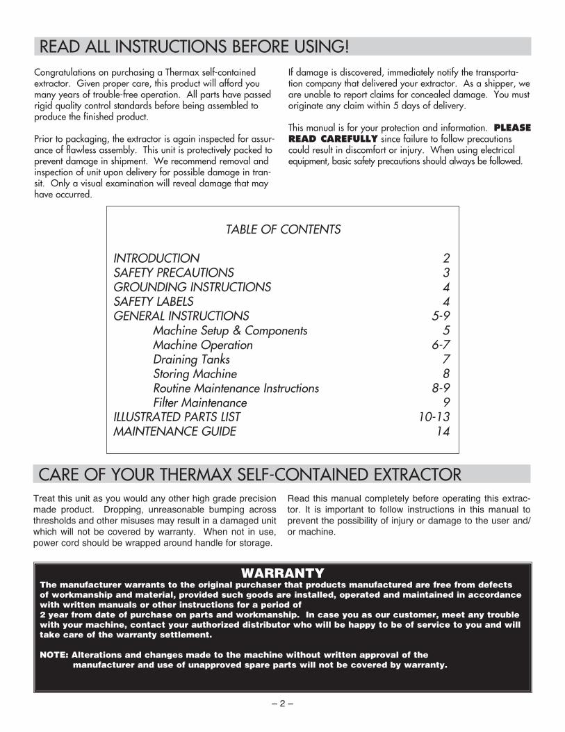
READ ALL INSTRUCTIONS BEFORE USING!
CARE OF YOUR THERMAX SELF-CONTAINED EXTRACTORTreat this unit as you would any other high grade precision made product. Dropping, unreasonable bumping across thresholds and other misuses may result in a damaged unit which will not be covered by warranty. When not in use, power cord should be wrapped around handle for storage.
Read this manual completely before operating this extrac-tor. It is important to follow instructions in this manual to prevent the possibility of injury or damage to the user and/or machine.
Congratulations on purchasing a Thermax self-contained extractor. Given proper care, this product will afford you many years of trouble-free operation. All parts have passed rigid quality control standards before being assembled to produce the finished product.
Prior to packaging, the extractor is again inspected for assur-ance of flawless assembly. This unit is protectively packed to prevent damage in shipment. We recommend removal and inspection of unit upon delivery for possible damage in tran-sit. Only a visual examination will reveal damage that may have occurred.
If damage is discovered, immediately notify the transporta-tion company that delivered your extractor. As a shipper, we are unable to report claims for concealed damage. You must originate any claim within 5 days of delivery.
This manual is for your protection and information. PLEASE READ CAREFULLY since failure to follow precautions could result in discomfort or injury. When using electrical equipment, basic safety precautions should always be followed.
TABLE OF CONTENTS
INTRODUCTION 2SAFETY PRECAUTIONS 3GROUNDING INSTRUCTIONS 4SAFETY LABELS 4GENERAL INSTRUCTIONS 5-9 Machine Setup & Components 5 Machine Operation 6-7 Draining Tanks 7 Storing Machine 8 Routine Maintenance Instructions 8-9 Filter Maintenance 9ILLUSTRATED PARTS LIST 10-13MAINTENANCE GUIDE 14
WARRANTYThe manufacturer warrants to the original purchaser that products manufactured are free from defects of workmanship and material, provided such goods are installed, operated and maintained in accordance with written manuals or other instructions for a period of 2 year from date of purchase on parts and workmanship. In case you as our customer, meet any trouble with your machine, contact your authorized distributor who will be happy to be of service to you and will take care of the warranty settlement. NOTE: Alterations and changes made to the machine without written approval of the manufacturer and use of unapproved spare parts will not be covered by warranty.
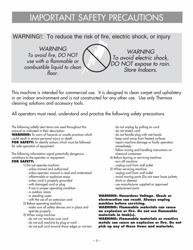
IMPORTANT SAFETY PRECAUTIONS
WARNING!: To reduce the risk of fire, electric shock, or injury
This machine is intended for commercial use. It is designed to clean carpet and upholstery in an indoor environment and is not constructed for any other use. Use only Thermax cleaning solutions and accessory tools.
All operators must read, understand and practice the following safety precautions.
WARNINGTo avoid fire, DO NOT use with a flammable or
combustible liquid to clean floor.
WARNINGTo avoid electric shock,
DO NOT expose to rain. Store Indoors.
– 3 –
The following safetly alert terms are used throughout this manual as indicated in their description:WARNING: To warn of hazards or unsafe practices which could result in severe personal injury or death.FOR SAFETY: To identify actions which must be followed for safe operation of equipment.
The following information signal potentially dangerous conditions to the operator or equipment:FOR SAFETY: 1) Do not operate machine: - unless trained and authorized - unless operator manual is read and understood - inflammable or explosive areas - unless cord is properly grounded - with damaged cord or plug - if not in proper operating condition - in outdoor areas - in standing water - with the use of an extension cord 2) Before operating machine: - make sure all safety devices are in place and operate properly 3) When using machine: - do not run machine over cord - do not pull machine by plug or cord - do not pull cord around sharp edges or corners
- do not unplug by pulling on cord - do not stretch cord - do not handle plug with wet hands - keep cord away from heated surfaces - report machine damage or faulty operation immediately - follow mixing and handling instructions on chemical containers 4) Before leaving or servicing machine: - turn off machine - unplug cord from wall outlet 5) When servicing machine: - unplug cord from wall outlet - avoid moving parts (Do not wear loose jackets, shirts or sleeves) - use manufacturer supplied or approved replacement parts
WARNING: Hazardous Voltage. Shock or electrocution can result. Always unplug machine before servicing.WARNING: Flammable materials can cause an explosion or fire. Do not use flammable materials in tank(s).WARNING: Flammable materials or reactive metals can cause an explosion or fire. Do not pick up any of these items and materials.
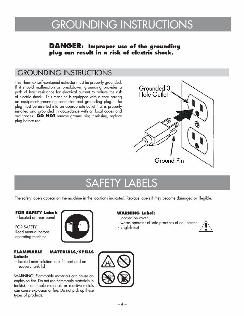
GROUNDING INSTRUCTIONS
DANGER: Improper use of the grounding plug can result in a risk of electric shock.
GROUNDING INSTRUCTIONSThis Thermax self-contained extractor must be properly grounded. If it should malfunction or breakdown, grounding provides a path of least resistance for electrical current to reduce the risk of electric shock. This machine is equipped with a cord having an equipment-grounding conductor and grounding plug. The plug must be inserted into an appropriate outlet that is properly installed and grounded in accordance with all local codes and ordinances. DO NOT remove ground pin; if missing, replace plug before use.
– 4 –
SAFETY LABELSThe safety labels appear on the machine in the locations indicated. Replace labels if they become damaged or illegible.
FOR SAFETY Label: - located on rear panel
FOR SAFETY: Read manual before operating machine.
WARNING Label: - located on cover - warns operator of safe practices of equipment - English text
FLAMMABLE MATERIALS/SPILLS Label: - located near solution tank fill port and on...recovery tank lid
WARNING: Flammable materials can cause an explosion fire. Do not use flammable materials in tank(s). Flammable materials or reactive metals can cause explosion or fire. Do not pick up these types of products.

– 5 –
MACHINE COMPONENTS & SETUP
GENERAL INSTRUCTIONS
1) main power ON/......OFF switch2) pump reset button3) brush reset button4) power cord wrap5) folding handle lock......knob
6) solution tank drain......hose7) solution switch8) folding handles9) recovery tank cover10) recovery tank11) solution tank
12) accessory tool......solution hose coupler13) accessory tool......vacuum hose port14) recovery shoe
11
10
9
12 13
14
Figure 1
Figure 4
1) Carefully check carton for signs of damage. Report damages at once to carrier. The machine is shipped fully assembled and is ready for use.
2) Adjust handle from transport position. To adjust, rotate handle knob to outward position and lift handle to desirable operating height, turn knob inward to lock handle (Figure 1).
3) Open cover and remove recovery tank from machine. Make sure the float shut-off screen and solution tank strainer are in place before use (Figure 2).
4) Using a clean bucket or hose, fill solution tank with 4 gal (15 L) of hot water, 140ºF (60ºC) maximum (Figure 3). Observe solution tank hose at rear of machine when filling. The hose indicates the amount of water in solution tank. (Figure 4) Do not use recovery tank to fill machine. Use a clean bucket.
5) Add a recommended Thermax carpet cleaner.
6) Replace recovery tank and close cover after filling.
7) Plug machine’s power cord into a grounded wall outlet.
ATTENTION: Do not use recovery tank to fill solution tank. Residual dirt or debris could cause damage to solution pump.WARNING: Flammable materials can cause an explosion or fire. Do not use flammable materials in tank(s).FOR SAFETY: When using machine, follow mixing and handling instructions on chemical containers.FOR SAFETY: Do not operate machine unless cord is properly grounded. Do not operate machine with the use of an extension cord.
Figure 2
Figure 3
FOR SAFETY: Do not operate machine unless operator manual is read and understood.
PRE-OPERATION 1) Vacuum carpet and remove other debris. 2) Perform MACHINE SETUP procedures. 3) Inspect power cord for damage.
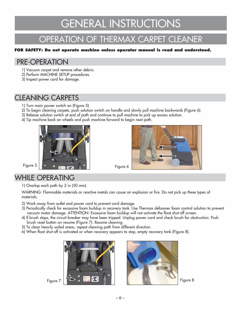
CLEANING CARPETS 1) Turn main power switch on (Figure 5). 2) To begin cleaning carpets, push solution switch on handle and slowly pull machine backwards (Figure 6). 3) Release solution switch at end of path and continue to pull machine to pick up excess solution. 4) Tip machine back on wheels and push machine forward to begin next path.
WHILE OPERATING 1) Overlap each path by 2 in (50 mm).
WARNING: Flammable materials or reactive metals can cause an explosion or fire. Do not pick up these types of materials.
2) Work away from outlet and power cord to prevent cord damage. 3) Periodically check for excessive foam buildup in recovery tank. Use Thermax defoamer foam control solution to prevent
vacuum motor damage. ATTENTION: Excessive foam buildup will not activate the float shut-off screen. 4) If brush stops, the circuit breaker may have been tripped. Unplug power cord and check brush for obstruction. Push
brush reset button on resume (Figure 7). Resume cleaning. 5) To clean heavily soiled areas, repeat cleaning path from different direction. 6) When float shut-off is activated or when recovery appears to stop, empty recovery tank (Figure 8).
– 6 –
GENERAL INSTRUCTIONSOPERATION OF THERMAX CARPET CLEANER
Figure 5 Figure 6
Figure 7 Figure 8
– 7 –
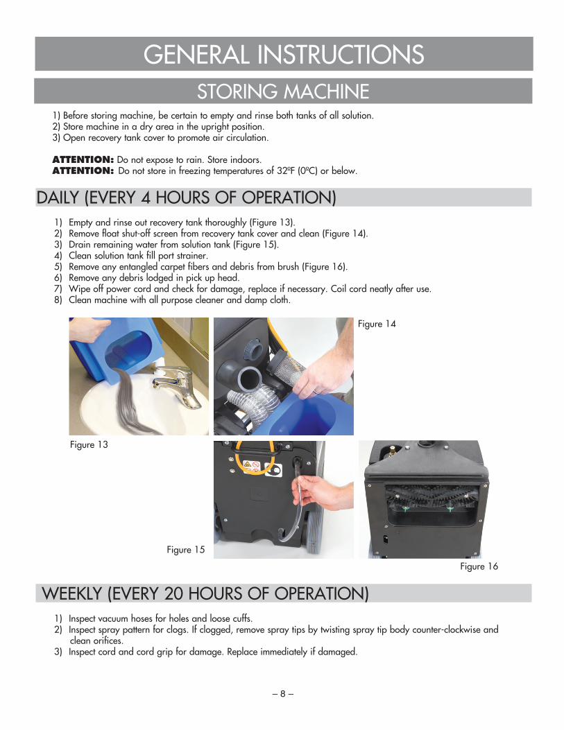
DRAINING RECOVERY TANK 1) Turn machine off and unplug power cord. 2) Open cover; lift recovery tank out and empty (Figure 11). NOTE:
Make sure to rinse out recovery tank after each use. Do not use this tank to fill machine with cleaning solution.
DRAINING SOLUTION TANK 1) Pull solution tank drain hose off of hose barb at rear of machine
and empty remaining solution (Figure 12). 2) Replace drain hose.
FOR SAFETY: When servicing machine, unplug cord from wall outlet.
GENERAL INSTRUCTIONS
DRAINING TANKS
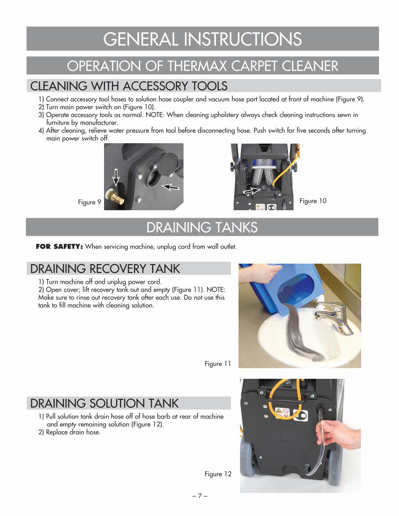
Figure 9 Figure 10
CLEANING WITH ACCESSORY TOOLS 1) Connect accessory tool hoses to solution hose coupler and vacuum hose port located at front of machine (Figure 9). 2) Turn main power switch on (Figure 10). 3) Operate accessory tools as normal. NOTE: When cleaning upholstery always check cleaning instructions sewn in
furniture by manufacturer. 4) After cleaning, relieve water pressure from tool before disconnecting hose. Push switch for five seconds after turning
main power switch off.
OPERATION OF THERMAX CARPET CLEANER
Figure 11
Figure 12
– 8 –
1) Before storing machine, be certain to empty and rinse both tanks of all solution. 2) Store machine in a dry area in the upright position. 3) Open recovery tank cover to promote air circulation.
ATTENTION: Do not expose to rain. Store indoors. ATTENTION: Do not store in freezing temperatures of 32ºF (0ºC) or below.
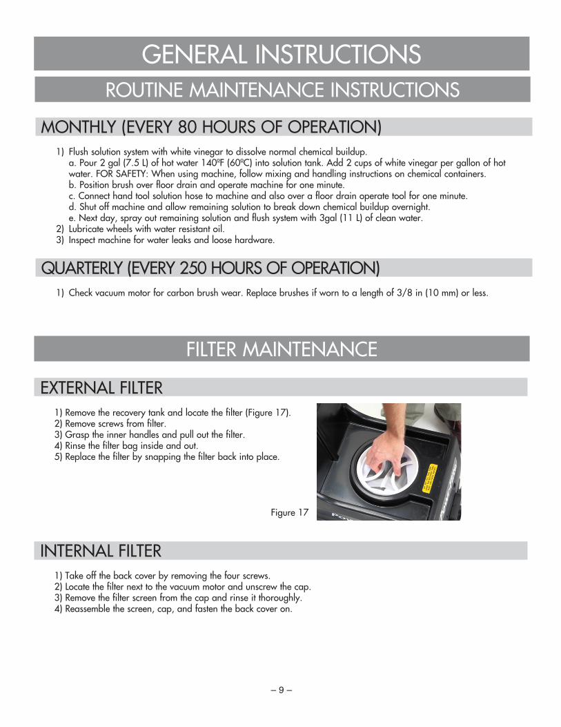
DAILY (EVERY 4 HOURS OF OPERATION) 1) Empty and rinse out recovery tank thoroughly (Figure 13). 2) Remove float shut-off screen from recovery tank cover and clean (Figure 14). 3) Drain remaining water from solution tank (Figure 15). 4) Clean solution tank fill port strainer. 5) Remove any entangled carpet fibers and debris from brush (Figure 16). 6) Remove any debris lodged in pick up head. 7) Wipe off power cord and check for damage, replace if necessary. Coil cord neatly after use. 8) Clean machine with all purpose cleaner and damp cloth.
WEEKLY (EVERY 20 HOURS OF OPERATION) 1) Inspect vacuum hoses for holes and loose cuffs. 2) Inspect spray pattern for clogs. If clogged, remove spray tips by twisting spray tip body counter-clockwise and clean orifices. 3) Inspect cord and cord grip for damage. Replace immediately if damaged.
GENERAL INSTRUCTIONS
Figure 13
Figure 14
Figure 15
Figure 16
STORING MACHINE
– 9 –
EXTERNAL FILTER 1) Remove the recovery tank and locate the filter (Figure 17). 2) Remove screws from filter. 3) Grasp the inner handles and pull out the filter. 4) Rinse the filter bag inside and out. 5) Replace the filter by snapping the filter back into place.
INTERNAL FILTER 1) Take off the back cover by removing the four screws. 2) Locate the filter next to the vacuum motor and unscrew the cap. 3) Remove the filter screen from the cap and rinse it thoroughly. 4) Reassemble the screen, cap, and fasten the back cover on.
FILTER MAINTENANCE
GENERAL INSTRUCTIONS
MONTHLY (EVERY 80 HOURS OF OPERATION) 1) Flush solution system with white vinegar to dissolve normal chemical buildup. a. Pour 2 gal (7.5 L) of hot water 140ºF (60ºC) into solution tank. Add 2 cups of white vinegar per gallon of hot
water. FOR SAFETY: When using machine, follow mixing and handling instructions on chemical containers. b. Position brush over floor drain and operate machine for one minute. c. Connect hand tool solution hose to machine and also over a floor drain operate tool for one minute. d. Shut off machine and allow remaining solution to break down chemical buildup overnight. e. Next day, spray out remaining solution and flush system with 3gal (11 L) of clean water. 2) Lubricate wheels with water resistant oil. 3) Inspect machine for water leaks and loose hardware.
QUARTERLY (EVERY 250 HOURS OF OPERATION) 1) Check vacuum motor for carbon brush wear. Replace brushes if worn to a length of 3/8 in (10 mm) or less.
ROUTINE MAINTENANCE INSTRUCTIONS
Figure 17

– 10 –
ILLUSTRATED PARTS LIST Motor/pump assembly

ref# item# description1 TRI-SC-00696 washer-plain #102 TRI-SC-01574 washer-lock (1/4")3 TRI-SC-01604 nut-finished hex #10-324 TRI-SC-01713 washer, lock #105 TRI-SC-02038 screw-phillips round head machine 1/4-20 x 1.006 TRI-SC-02625 nut-hex. lock (keps) #10-327 TRI-SC-03218 washer-plain 1/48 TRI-SC-03261 screw, tct panhead, #10-32 x 3/89 TRI-SC-04442 screw-phillips pan head machine 1/4-20 x 1/210 TRI-SC-05209 bearing-radial ball11 TRI-SC-05282 jam nut12 TRI-SC-11007 washer-lock (i/t) #1013 TRI-SC-11733 screw-socket hd cap #10-32 x 1-1/414 TRI-SC-12554 washer-plain .500 id (natural nyl)15 TRI-SC-14858 clamp-hose (screw)16 TRI-SC-14881 brass fitting- nipple, 1/4" fnpt x 1/4" qc17 TRI-SC-15330 strain relief bushing18 TRI-SC-16091 clamp19 TRI-SC-17160 1/4 x 3/4-20 screw20 TRI-SC-17508 nut-finished hex 1/4-2021 TRI-SC-19149 fitting-brs.plug 1/8 mpt hex socket22 TRI-SC-19157 bearing block-brush23 TRI-SC-19158 bearing seal24 TRI-SC-19161 pulley timing-motor25 TRI-SC-19190 spacer 5/16" delrin26 TRI-SC-19228 gasket-bearing block27 TRI-SC-32175 pulley timing-motor
ref# item# description28 TRI-SC-32183 plug in elbow 3/8"29 TRI-SC-32186 male conector 3/8"30 TRI-SC-32245 lock washer 5/16"31 TRI-SC-32905 clevis pin spring32 TRI-SC-32936 2" vac hose33 TRI-SC-32937 spray nozzle tip34 TRI-SC-32946 vacuum bracket35 TRI-SC-32948 pump bracket36 TRI-SC-32959 10.25" brush axle37 TRI-SC-32962 solution pump38 TRI-SC-32963 solenoid valve39 TRI-SC-32973 spray manifold40 TRI-SC-32974 spray cap connector41 TRI-SC-32975 spray nozzle cap42 TRI-SC-32982 brush-20'' roller, carpet scrubbing43 TRI-SC-33000 1/4 nptf f x f x m tee44 TRI-SC-33002 2" threaded pipe45 TRI-SC-33006 hose-3/8" x 4.5" lg. (natural tube)46 TRI-SC-33007 hose-3/8" x 14" lg. (natural tube)47 TRI-SC-33450 gasket-lower housing (large)48 TRI-SC-33015 gasket-lower housing (small)49 TRI-SC-33061 bridge rectifier-25 a50 TRI-SC-33063 screw-socket hd cap #10-32 x 1-5/851 TRI-SC-33073 17" belt - 9815052 TRI-SC-33086 120v 1200w tangential bypass vac motor53 TRI-SC-33090 motor/pump housing54 TRI-SC-33094 #10-32 x 3/8" flat head screw55 TRI-SC-33427 bottom plate assembly56 TRI-SC-X9002+ motor-brush
Motor/pump assembly continued
ILLUSTRATED PARTS LIST
– 11 –
ref# item# description1 TRI-SC-11007 washer-lock (i/t) #102 TRI-SC-32654 #10 plastite hi-lo screw, .500 long3 TRI-SC-32956 vacuum nozzle-back4 TRI-SC-32957 vacuum nozzle-front5 TRI-SC-32958 intake cap
Vacuum nozzle assembly

ILLUSTRATED PARTS LIST
ref# item# description1 TRI-SC-03261 screw, tct panhead, #10-32 x 3/82 TRI-SC-04145 grommet, 3/8" id x 9/64 wall3 TRI-SC-04442 screw-phillips pan head machine 1/4-20 x 1/24 TRI-SC-05769 screw-phillips flat head machine #8-32 x 5/85 TRI-SC-15475 screw-phillips flat head machine #8-32 x 3/86 TRI-SC-17392 clamp, cable (cch 5/16)7 TRI-SC-18119 nut, thumb 5/16-188 TRI-SC-18486 fitting, plastic elbow9 TRI-SC-19121 switch-push button10 TRI-SC-19145 nut-hex lock (nylon insert) #10-2411 TRI-SC-19798 bracket grvd handle12 TRI-SC-30074 #8-32 hex lock nut, steel13 TRI-SC-30507 1/2" external snap ring14 TRI-SC-32181 stem adapter 3/8"15 TRI-SC-32182 union tee 3/8"16 TRI-SC-32183 plug in elbow 3/8"17 TRI-SC-32186 male conector 3/8"18 TRI-SC-32257 fitting, stem 3/8"x3/8"19 TRI-SC-32258 hose-3/8" x 2" lg. (natural tube)20 TRI-SC-32935 3 amp circuit breaker
ref# item# description21 TRI-SC-32938 inline filter22 TRI-SC-33901 recovery tank blue23 TRI-SC-32942 solution tank24 TRI-SC-32944 back cover25 TRI-SC-32952 control panel assembly26 TRI-SC-32954 hinge bar27 TRI-SC-32955 wheel axle28 TRI-SC-32964 10 amp circuit breaker29 TRI-SC-32965 hinge bar sleeve30 TRI-SC-32966 on/off switch-small extractor31 TRI-SC-32969 8" wheel32 TRI-SC-32970 bag filter33 TRI-SC-32989 tubular handle assembly34 TRI-SC-33003 cord-power 16/3 awg x 20' (yellow)35 TRI-SC-33006 hose-3/8" x 4.5" lg. (natural tube)36 TRI-SC-33008 hose, solution drain37 TRI-SC-33010 hose-3/8" x 11.5" lg. (natural tube)38 TRI-SC-33012 cord wrap bracket39 TRI-SC-33078 carriage bolt, #10-24 x 1.5l40 TRI-SC-PD8+ strain relief (liq. tite)
Solution tank assembly
– 12 –

ref# item# description1 TRI-SC-07870 washer-lock(i/t)1/4"2 TRI-SC-15139 terminal-q.d. female 1/4'3 TRI-SC-15391 1/4" piggyback terminal4 TRI-SC-17177 screw-hex head cap 1/4-20 x 1-1/45 TRI-SC-32998 solution tank label-bilingual6 TRI-SC-32999 solution tank label-bilingual7 TRI-SC-33066 5/16 id x 15/32 od steel washer8 TRI-SC-33408 shoulder bolt, 1/4-20 x 1.25l, ss NOTILLUSTRATED TRI-SC-32971 discharge hose TRI-SC-32972 intake hose TRI-SC-32994 decal, pictoral instruction TRI-SC-32995 decal-warning TRI-SC-32996 decal, pictoral hazard TRI-SC-32997 decal, read instructions pictoral TRI-SC-32999 decal recovery tank warning
ILLUSTRATED PARTS LIST Exterior assembly
ref# item# description1 TRI-SC-15092 nut hex flanged lock 1-1/2 npt2 TRI-SC-16091 clamp3 TRI-SC-32950 top cover4 TRI-SC-32976 1-1/2 elbow m x spigot5 TRI-SC-32977 ball float6 TRI-SC-32979 45 degree elbow7 TRI-SC-33013 gasket-cover plate8 TRI-SC-33087 cover9 TRI-SC-33094 #10-32 x 3/8" flat head screw
Top cover assembly
– 13 –

SAVE THESE INSTRUCTIONS
MAINTENANCE GUIDE Machine does not operate
CAUSE: SOLUTION:1) Faulty switches or wiring. 1) Contact manufacturer or service center.2) Faulty power cord. 2) Contact manufacturer or service center.3) Building circuit breaker tripped. 3) Reset circuit breaker according to operating instructions.
Brush motor does not operateCAUSE: SOLUTION:1) Brush motor circuit breaker tripped. 1) Let motor cool and reset brush motor breaker button at rear of machine.2) Switch not pushed. 2) Push solution switch.3) Loose or broken brush belt. 3) Contact manufacturer or service center.4) Faulty switch or wiring. 4) Contact manufacturer or service center.5) Faulty brush motor. 5) Contact manufacturer or service center.
Solution pump does not operateCAUSE: SOLUTION:1) Solution pump circuit breaker tripped. 1) Let pump cool and reset pump breaker button at rear or machine.2) Switch not pushed. 2) Push solution switch.3) Faulty switch or wiring. 3) Contact manufacturer or service center.4) Faulty solution pump motor. 4) Contact manufacturer or service center.
Vacuum motor does not operateCAUSE: SOLUTION:1) Loose or broken wiring. 1) Contact manufacturer or service center.2) Faulty main power switch. 2) Contact manufacturer or service center.3) Defective vacuum motor. 3) Contact manufacturer or service center. 4) Worn carbon brushes. 4) Contact manufacturer or service center.
Poor solution pick-upCAUSE: SOLUTION:1) Defective recovery tank cover gasket. 1) Replace gasket.2) Clogged float shut-off screen. 2) Open recovery tank cover and clean lint off screen.3) Accessory tool vacuum hose port cover is 3) Check vacuum hose port cover. loose or missing.4) Loose vacuum hose cuffs. 4) Secure connections under cover.5) Pulling machine too fast. 5) Slow down cleaning process.
Uneven or no spray
1) Clogged spray tips. 1) Clean or replace tips.2) Improper spray tip size or spray angle. 2) Replace with proper tips.3) Clogged solenoid valve. 3) Contact manufacturer or service center.4) Worn spray tips. 4) Replace spray tips.5) Solution tank low or empty. 5) Refill solution tank.6) Faulty solution pump. 6) Contact manufacturer or service center.7) Pump needs priming. 7) Prime pump by pressing solution hose coupler tip located at front of machine.