Self-Centering Steel Frame Systems NEESR-SG: Self-Centering Damage-Free Seismic- Resistant Steel...
44
Self-Centering Steel Frame Systems NEESR-SG: Self-Centering Damage-Free Seismic-Resistant Steel Frame Systems Project Team Richard Sause, James Ricles, David Roke, Choung-Yeol Seo, Michael Wolski, Geoff Madrazo ATLSS Center, Lehigh University Maria Garlock, Erik VanMarcke, Li-Shiuan Peh Princeton University Judy Liu Purdue University Keh-Chyuan Tsai NCREE, National Taiwan University
-
Upload
blanca-warrick -
Category
Documents
-
view
240 -
download
11
Transcript of Self-Centering Steel Frame Systems NEESR-SG: Self-Centering Damage-Free Seismic- Resistant Steel...
Self-Centering Steel Frame Systems
NEESR-SG: Self-Centering Damage-Free Seismic-Resistant Steel Frame Systems
Project TeamRichard Sause, James Ricles, David Roke,
Choung-Yeol Seo, Michael Wolski, Geoff Madrazo ATLSS Center, Lehigh University
Maria Garlock, Erik VanMarcke, Li-Shiuan PehPrinceton University
Judy LiuPurdue University
Keh-Chyuan TsaiNCREE, National Taiwan University
Current NEESR Project
NEESR-SG: Self-Centering Damage-Free Seismic-Resistant
Steel Frame Systems
This material is based on work supported by the National Science Foundation, Award No. CMS-0420974, in the George E. Brown, Jr. Network for Earthquake Engineering Simulation Research (NEESR) program, and Award No. CMS-0402490 NEES Consortium Operation.

Motivation: Expected Damage for Conventional Steel Frames
Conventional Moment Resisting Frame System
(b)
(a)
Reduced beam section (RBS) beam-column test specimen with slab: (a) at 3% drift, (b) at 4% drift.

Self Centering (SC) Seismic-Resistant System Concepts
Discrete structural members are post-tensioned to pre-compress joints.
Gap opening at joints at selected earthquake load levels provides softening of lateral force-drift behavior without damage to members.
PT forces close joints and permanent lateral drift is avoided.
M

3660 to 4120 mm
6100 to 8540 mm
W24x62 (Fy 248 MPa),or W36x150 (Fy 350 MPa)
W14x311, W14x398 (Fy 350 MPa)or CFT406x406x13 (Fy 345 MPa)
PT Strands
Previous Work on SC Steel Moment Resisting (MRF) Connections
MRF Subassembly with PT Connections
-500
-400
-300
-200
-100
0
100
200
300
400
500
-150 -100 -50 0 50 100 150
Lateral Displacement - (mm)
Late
ral L
oad
- H
(K
N) FR
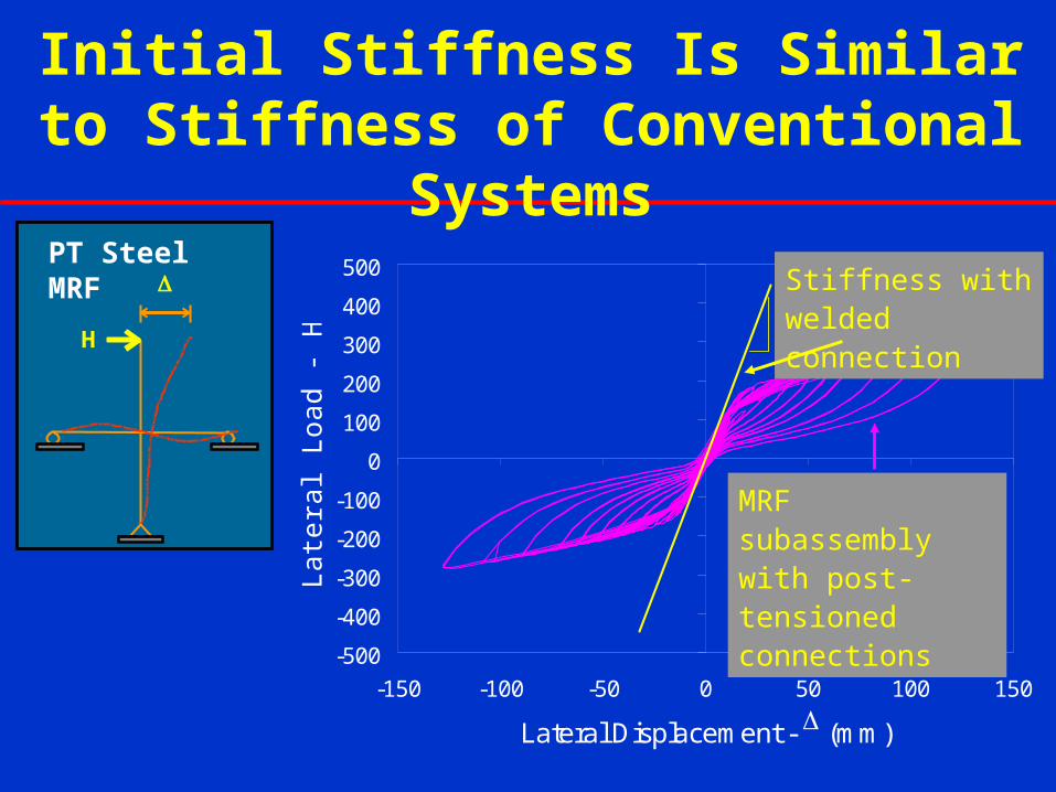
Stiffness with welded connection
Initial Stiffness Is Similar to Stiffness of Conventional Systems
H
PT Steel MRF
MRF subassembly with post-tensioned connections

Steel MRF subassembly with post-tensioned connections and angles at 3% drift
Lateral Force-Drift Behavior Softens Due to Gap Opening

Lateral Force-Drift Behavior Softens Without Significant Damage
• Conventional steel MRFs soften by inelastic deformation, which damages main structural members and results in residual drift
• SC steel MRF softens by gap opening and reduced contact area at joints
H
-600
-400
-200
0
200
400
600
-8 -6 -4 -2 0 2 4 6 8
Displacement, (in)
Lat
eral
Lo
ad, H
(ki
ps)
Post-Tensioned Connection
Welded Connection

Energy Dissipation from Energy Dissipation (ED) Elements
-400
-300
-200
-100
0
100
200
300
400
-150 -100 -50 0 50 100 150
Lateral Displacement, [mm]
Lat
eral
Lo
ad,
H [
KN
]
Specimen PC2L6x6x5/16, g/t = 4
Specimen PC4L8x8x5/8, g/t = 4
Steel MRF subassemblies with post-tensioned connections with different size ED elements.
H
Steel MRF

Limited, Repairable Damage
@ 4% DriftBefore testing After testing
Angle fracture
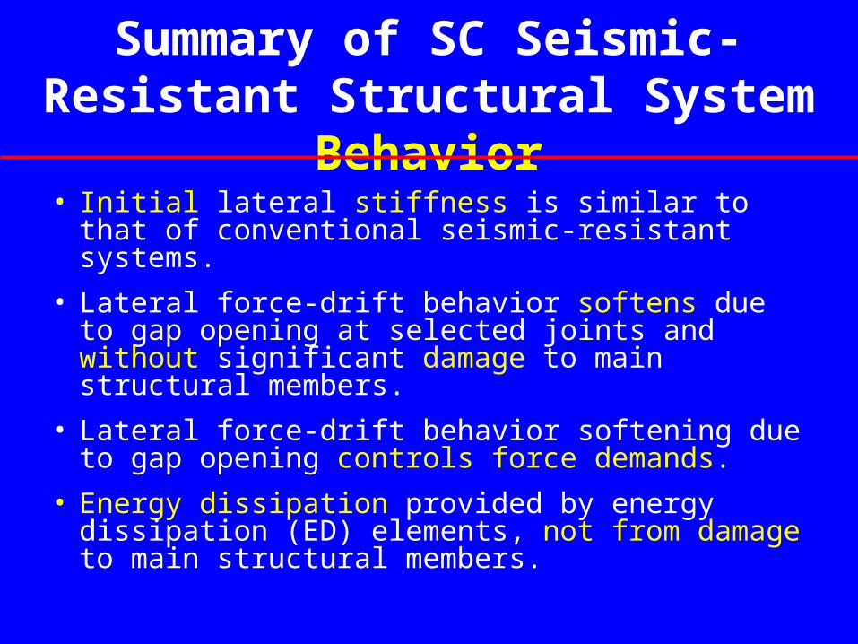
Summary of SC Seismic-Resistant Structural System Behavior
• Initial lateral stiffness is similar to that of conventional seismic-resistant systems.
• Lateral force-drift behavior softens due to gap opening at selected joints and without significant damage to main structural members.
• Lateral force-drift behavior softening due to gap opening controls force demands.
• Energy dissipation provided by energy dissipation (ED) elements, not from damage to main structural members.
NEESR-SG: Self-Centering Damage-Free Seismic-
Resistant Steel Frame Systems
• Project Scope.
• Project Goals.
• Status of Selected Research Tasks.
• Summary.

NEESR-SG: SC Steel Frame Systems Project Scope
• Develop two SC steel frame systems:– Moment-resisting frames (SC-MRFs).
– Concentrically-braced frames (SC-CBFs).
• Conduct large-scale experiments utilizing:– NEES ES (RTMD facility) at Lehigh.
– non-NEES laboratory (Purdue).
– international collaborating laboratory (NCREE)
• Conduct analytical and design studies of prototype buildings.
• Develop design criteria and design procedures.
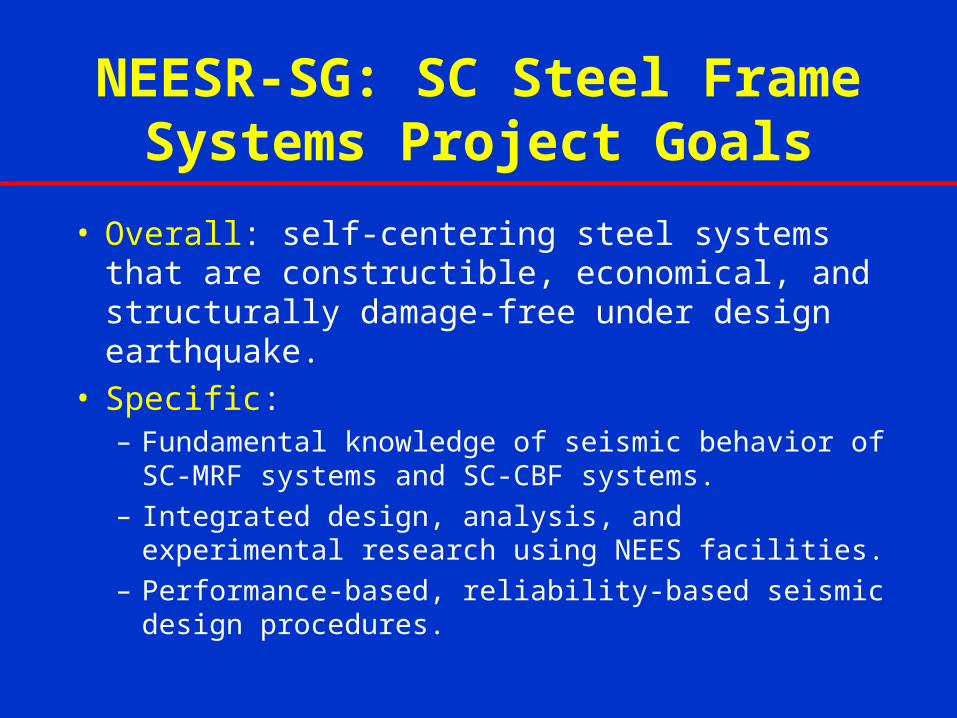
NEESR-SG: SC Steel Frame Systems Project Goals
• Overall: self-centering steel systems that are constructible, economical, and structurally damage-free under design earthquake.
• Specific:– Fundamental knowledge of seismic behavior of SC-
MRF systems and SC-CBF systems.– Integrated design, analysis, and experimental
research using NEES facilities.– Performance-based, reliability-based seismic design
procedures.

NEESR-SG: Self-Centering Damage-Free Seismic-
Resistant Steel Frame Systems
• Project Scope.
• Project Goals.
• Status of Selected Research Tasks.
• Summary.

NEESR-SG: SC Steel Frame Systems Project Research Tasks
1. Develop reliability-based seismic design and assessment procedures.
2. Develop SC-CBF systems.3. Further develop SC-MRF systems.4. Develop energy dissipation elements for SC-MRFs and SC-CBFs.5. Develop sensor networks for damage monitoring and integrity
assessment.6. Design prototype buildings.7. Perform nonlinear analyses of prototype buildings.8. Conduct large-scale laboratory tests of SC-MRFs and SC-CBFs.9. Collaborate on 3-D large-scale laboratory tests on SC-MRF and SC-
CBF systems.

Task 2. Develop SC-CBF Systems: SC-CBF System Concept
Rocking behavior of simple SC-CBF system.

More Complex SC-CBF Configurations Being Considered
basebase
V
P01P01+P
g g
g
g
g
g
g
g
g
g
g
g
P02P02+P
V
col
roof

SC-CBF Design Criteria
Δgap
PT steel yields Member yields
Column
Decompression
PT Yielding
Significant
Yielding of
Frame
Members
Failure of
Frame
Members
DBE
MCE
Lateral Force
Roof Drift
IO CPLS

Current Work on SC-CBF Systems
• Evaluate frame configurations.
• Evaluate effect of energy dissipation (ED) elements.
• Develop and evaluate performance-based design approach.
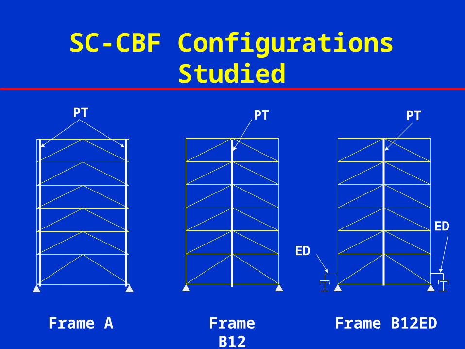
SC-CBF Configurations Studied
Frame A Frame B12 Frame B12ED
PT
ED
PT PT
ED
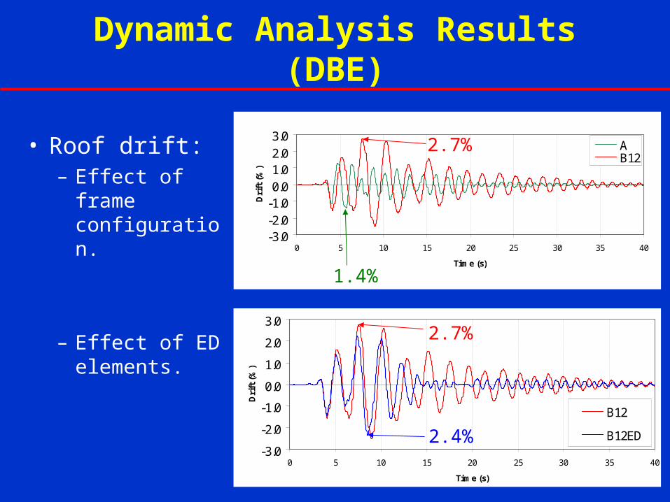
Dynamic Analysis Results (DBE)
• Roof drift:– Effect of
frame configuration.
– Effect of ED elements.
-3.0
-2.0
-1.0
0.0
1.0
2.0
3.0
0 5 10 15 20 25 30 35 40
Time (s)
Dri
ft (
%)
B12
B12ED2.4%
2.7%
-3.0-2.0-1.00.01.02.03.0
0 5 10 15 20 25 30 35 40
Time (s)D
rift
(%
)
AB12
1.4%
2.7%
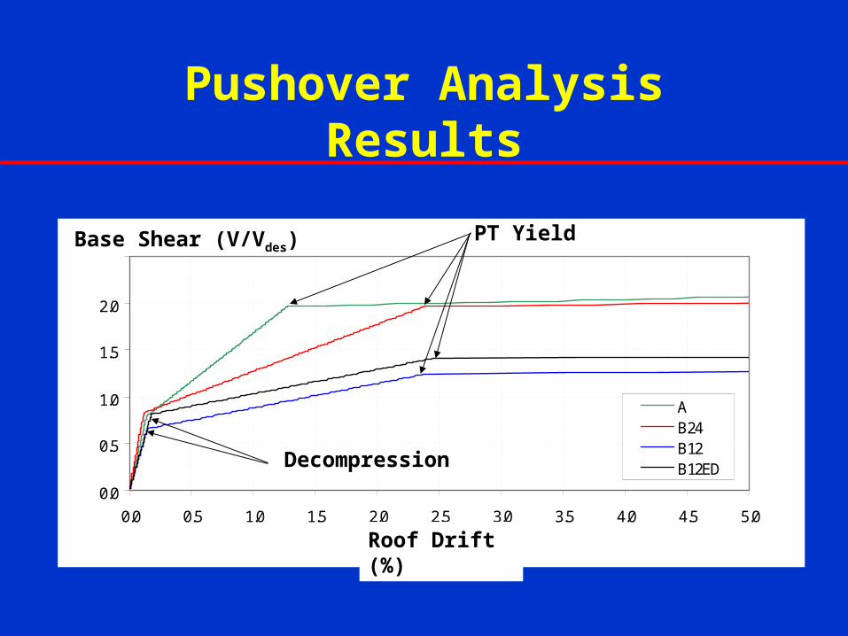
Pushover Analysis Results
0.0
0.5
1.0
1.5
2.0
2.5
0.0 0.5 1.0 1.5 2.0 2.5 3.0 3.5 4.0 4.5 5.0Drift (% )
V/V
des
AB24B12B12ED
PT Yield
Decompression
Roof Drift (%)
Base Shear (V/Vdes)

Preliminary Results for SC-CBF
• Dynamic analysis results indicate self-centering behavior is achieved under DBE.
• Frame A has lower drift capacity before PT yielding than Frame B:– PT steel is at column lines rather than mid-bay.
• Frame A also has lower drift demand.
• Energy dissipation helps to reduce drift demand and improve response.
Task 3. Further Develop SC-MRF Systems: Current Work
• Study of interaction between SC-MRFs and floor diaphragms by Princeton and Purdue.
• SC column base connections for SC-MRFs being studied by Purdue.

Interaction of SC-MRFs and Floor Diaphragms (Princeton)
Approach 1. Transmit inertial forces from floor diaphragm without excessive restraint of connection regions using flexible collectors.
gapr
gapgapgap
Collector Beams

Interaction of SC-MRFs and Floor Diaphragms (Purdue)
Approach 2. Transmit inertial forces from floor diaphragm within one (composite) bay for each frame.

SC Column Base Connections
for SC-MRFs (Purdue)Reinforcing Plate
Slotted Keeper Angle
Post-Tensioned Bars
Energy Dissipation Plate
Beam at Grade
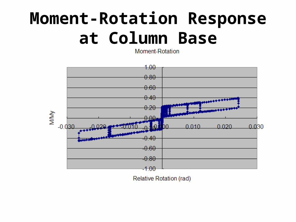
Moment-Rotation Response at Column Base
Identifying appropriate level of column base moment capacity and connection details, leading to laboratory experiments.
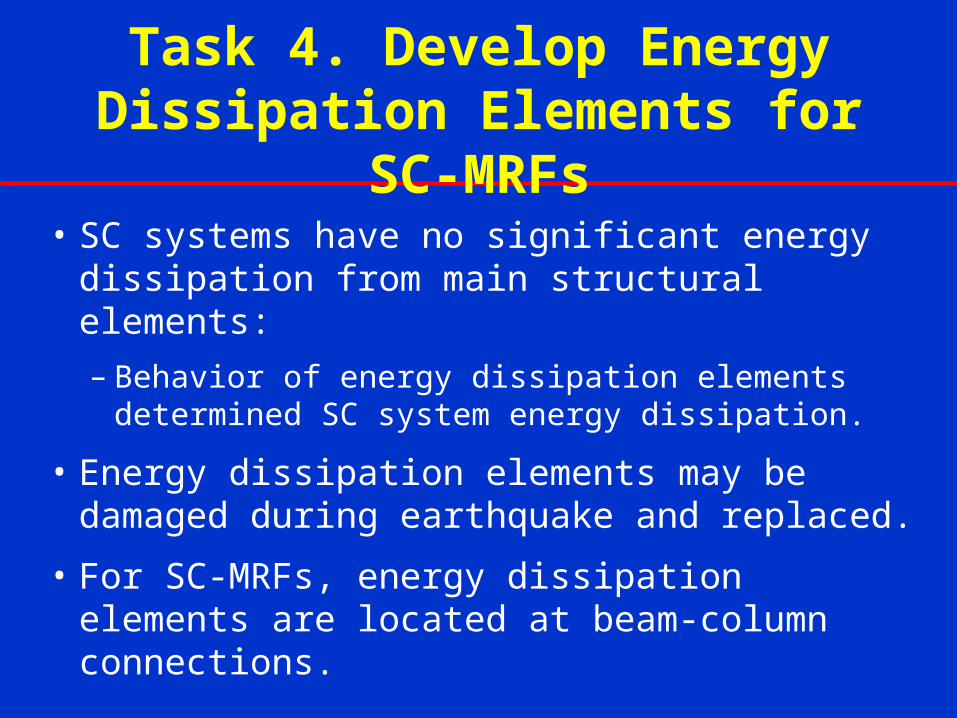
Task 4. Develop Energy Dissipation Elements for SC-MRFs
• SC systems have no significant energy dissipation from main structural elements:
– Behavior of energy dissipation elements determined SC system energy dissipation.
• Energy dissipation elements may be damaged during earthquake and replaced.
• For SC-MRFs, energy dissipation elements are located at beam-column connections.
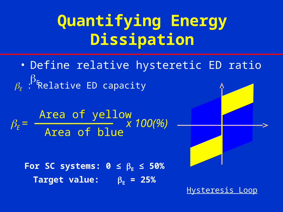
Quantifying Energy Dissipation
• Define relative hysteretic ED ratio E
E: Relative ED capacity
For SC systems: 0 ≤ E ≤ 50%
Target value: E = 25%
E = x 100(%)
Area of yellow
Area of blue
Hysteresis Loop

ED Element Assessment
• Consider several ED elements:– Metallic yielding, friction, viscoelastic,
elastomeric, and viscous fluid.
• Evaluation criteria:– Behavior, force capacity versus size,
constructability, and life-cycle maintenance.
• Friction ED elements selected for further study.
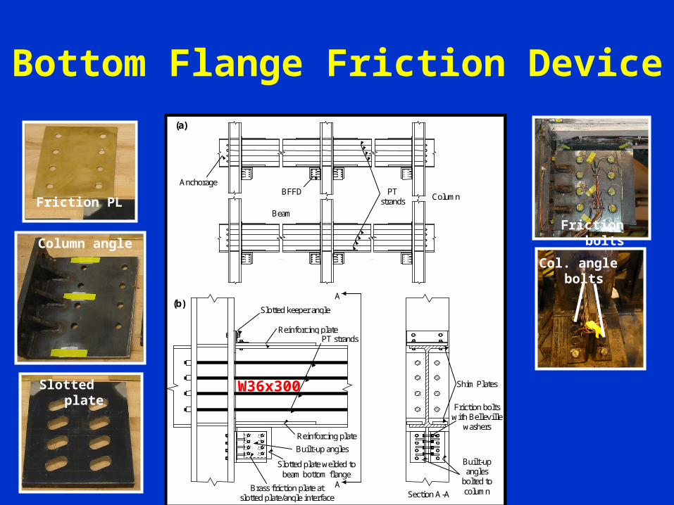
Bottom Flange Friction Device
Friction bolts with Belleville
washers
Anchorage
Section A-A
Reinforcing plate
Slotted plate welded to beam bottom flange
Built-up angles
bolted to column Brass friction plate at
slotted plate/angle interface
Shim Plates
(a)
PT strands
Beam
Column BFFD
A
Reinforcing plate
(b)
A
Slotted keeper angle
PT strands
Built-up angles
Col. angle bolts
Friction bolts
Column angle
Slotted plate
Friction PL
W36x300

BFFD Moment Contribution
• BFFD contribution to connection moment capacity
MFf = Ff∙rMFf
+ = Ff ∙r+
MFf- = Ff ∙r -
|MFf+ | > |MFf
- |
MFf+
MFf-
r
r
Ff Ff
r+
r-
MFf+
MFf-
r
r
Ff Ff
r+
r-
COR+
COR-

Test Setup
Test specimen subassembly
N S
W21x111
V
Hydraulic actuator
Beam
BFFD
Column
PT strands
12’-
2 ½
”
– Denotes lateral bracing
Reaction wall
Strong floor
Clevis plates
Test specimen subassembly
N S
W21x111
V
Test specimen subassembly
N S
W21x111
V
Hydraulic actuator
Beam
BFFD
Column
PT strands
12’-
2 ½
”
– Denotes lateral bracing
Reaction wall
Strong floor
Clevis platesHydraulic actuator
Beam
BFFD
Column
PT strands
12’-
2 ½
”
– Denotes lateral bracing
Reaction wall
Strong floor
Clevis platesHydraulic actuator
Beam
BFFD
Column
PT strands
12’-
2 ½
”
– Denotes lateral bracing
Reaction wall
Strong floor
Clevis platesHydraulic actuator
Beam
BFFD
Column
PT strands
12’-
2 ½
”
– Denotes lateral bracing
Reaction wall
Strong floor
Clevis plates
Test setup elevation Test setup
Bra
cing
Bra
cin
g
BFFD
Beam
PT Strands
Column
3/5 Scale
W21x111

Test Matrix
CS: Cyclic Symmetric EQ: Chi-Chi MCE Level Earthquake Response
Test No.
Loading Protocol
r,max (rads)
Experimental
Parameter
1 CS 0.035 Reduced Friction Force
2 CS 0.030 Design Friction Force
3 CS 0.030 Fillet Weld Repair
4 EQ 0.025 Response to EQ Loading
5 CS 0.065 Effect of Bolt Bearing
6 CS 0.035 Assess Column L Flex., CJP
7 CS 0.065 Effect of Bolt Bearing, CJP

Test 2: Design Friction Force
Beginning of Test 2
r = +0.03 rads r = -0.03 rads

Test 2: Response
-1.0
-0.5
0.0
0.5
1.0
-0.04 -0.03 -0.02 -0.01 0.00 0.01 0.02 0.03 0.04
Rotation, r (rads)
No
rma
lize
d M
om
en
t, M
/Mp
,n
theoretical decompression
theoretical decompression
stiffness reduction
stiffness reduction
imminent gap opening
imminent gap opening
M+
M-r-
r+
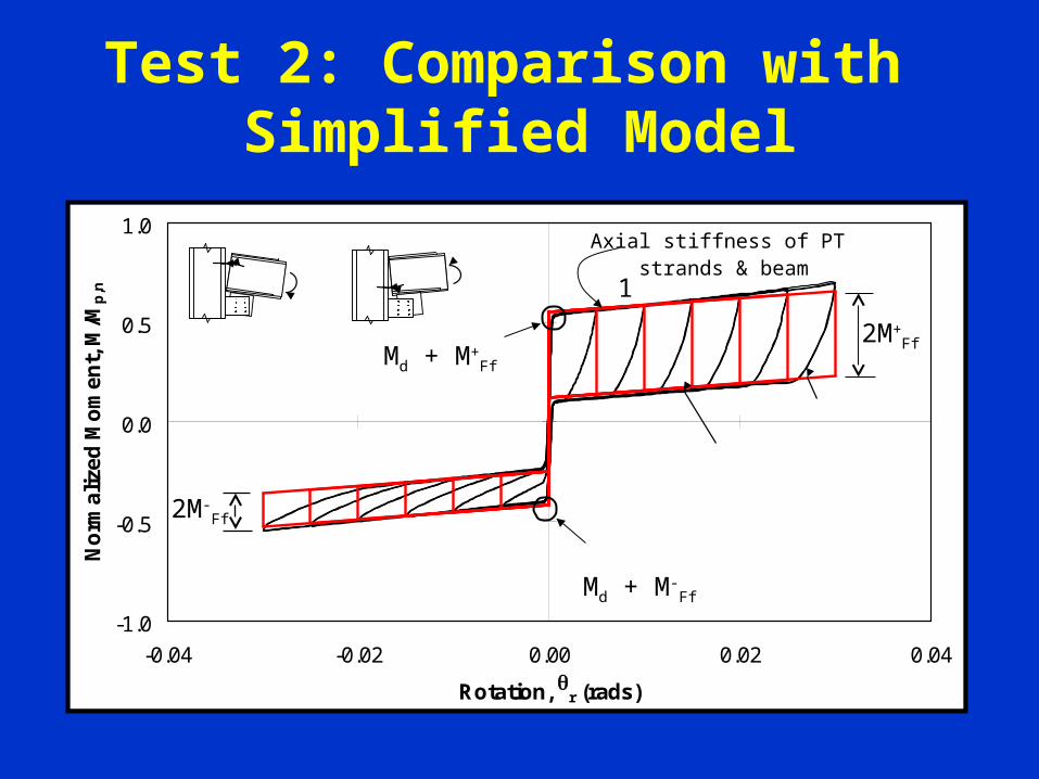
Test 2: Comparison with Simplified Model
-1.0
-0.5
0.0
0.5
1.0
-0.04 -0.02 0.00 0.02 0.04
Rotation, r (rads)
No
rmal
ized
Mo
men
t, M
/Mp
,n
experiment
model
M+
M-r-
r+
(b) Test 2
Md + M+Ff
2M-Ff
2M+Ff
1
Axial stiffness of PT strands & beam
Md + M-Ff

Results for ED Elements for SC-MRFs
• Friction ED element:– Reliable with repeatable and predictable behavior.– Large force capacity in modest size.
• BFFD:– Provides needed energy dissipation for SC-MRF
connections.– When anticipated connection rotation demand is
exceeded, friction bolts can be designed to fail in shear without damage to other components.

Task 8. Conduct Large-Scale Laboratory Tests
• Two specimens, one SC-MRF and one SC-CBF, tested at Lehigh NEES ES (RTMD facility).
• 2/3-scale 4 story frame.
• Utilize hybrid test method (pseudo dynamic with analytical and laboratory substructures).
• Utilize real-time hybrid test method, if energy dissipation elements are rate-sensitive.

9. Collaborate on 3-D Large-Scale Laboratory Tests
• Large-scale 3-D SC steel frame system tests at NCREE in Taiwan under direction of Dr. K.C. Tsai.
• Interaction of SC frame systems with floor diaphragms and gravity frames will be studied.
• 3-D tests are part of Taiwan program on SC systems.
• Project team is collaborating with Taiwan researchers:
– US-Taiwan Workshop on Self-Centering Structural Systems, June 6-7, 2005, at NCREE.
– 2nd workshop planned for October 2006 at NCREE.
Summary
• Two types of SC steel frame systems are being developed:– Moment-resisting frames (SC-MRFs).– Concentrically-braced frames (SC-CBFs).
• Research plan includes 9 major tasks:– Significant work completed on 7 tasks.– Numerous conference publications available from
current project.• Large-scale experiments utilizing NEES ES at
Lehigh are being conducted.• Ongoing collaboration with NCREE in Taiwan.

Self-Centering Steel Frame Systems
Thank you.