Self-assembling Peptide-Carbon Nanotube Dispersions and ...
139
Self-assembling Peptide-Carbon Nanotube Dispersions and Hydrogels for Tissue Engineering and Biosensor Applications by Mohammadali Sheikholeslam A thesis presented to the University of Waterloo in fulfillment of the thesis requirement for the degree of Doctor of Philosophy in Chemical Engineering - Nanotechnology Waterloo, Ontario, Canada, 2015 ©Mohammadali Sheikholeslam 2015
Transcript of Self-assembling Peptide-Carbon Nanotube Dispersions and ...
Self-assembling Peptide-Carbon Nanotube
Dispersions and Hydrogels for Tissue
Engineering and Biosensor Applications
by
Mohammadali Sheikholeslam
A thesis
presented to the University of Waterloo
in fulfillment of the
thesis requirement for the degree of
Doctor of Philosophy
in
Chemical Engineering - Nanotechnology
Waterloo, Ontario, Canada, 2015
©Mohammadali Sheikholeslam 2015

ii
AUTHOR'S DECLARATION
This thesis consists of material all of which I authored or co-authored: see Statement of Contributions
included in the thesis. This is a true copy of the thesis, including any required final revisions, as
accepted by my examiners.
I understand that my thesis may be made electronically available to the public.

iii
STATEMENT OF CONTRIBUTIONS
Chapter 3 of this thesis is adapted from a paper “Sheikholeslam, M.; Pritzker, M.; Chen, P.
Dispersion of multi-walled carbon nanotubes in water using ionic-complementary peptides.
Langmuir, 2012, 28, 12550–12556”.
Chapter 4 of this thesis is adapted from a paper “Sheikholeslam, M.; Pritzker, M.; Chen, P. Hybrid
peptide–carbon nanotube dispersions and hydrogels. Carbon, 2014, 71, 284–293”.
iv
Abstract
Carbon nanotubes (CNTs) are attractive functional materials for use in a broad range of fields due to
their unique mechanical and electrical properties. However, their hydrophobic nature is a major
problem for some of these applications. Several approaches such as dispersing them in organic
solutions and covalently or non-covalently modifying them have been developed to make CNTs
usable for desired applications. Since organic solutions can be problematic for bio-applications and
covalent modification can introduce defects into the CNT structure (responsible for its unique
properties), the approach of making non-covalent modification is more promising. Different types of
polymers and surfactants have been used so far in this way. In the past two decades, self-assembling
peptides have emerged as promising functional nanomaterials capable of use for different bio-
applications. Employing biocompatible self-assembling peptides for CNT dispersion not only
removes the first obstacle to use CNTs in solution, but also can result in a new class of hybrid
nanomaterials benefitting from the synergistic effects of peptides and CNTs. To the best of our
knowledge, this is the first work reporting the dispersion of CNTs using β-sheet-forming self-
assembling ionic-complementary peptides. Also this is the first study on the application of peptide-
CNT hybrid dispersions and hydrogels for biosensor and tissue engineering applications.
This thesis focuses on the modification of CNTs with self-assembling peptides, characterization of
the resulting hybrid dispersions and their application for biosensor development and scaffolding for
tissue engineering and cancer spheroid studies. In particular, the study includes the following topics:
(i) characterization of the dispersions of multi-walled carbon nanotubes (MWNTs) modified with
EFK16-II peptide, (ii) AFM characterization of dispersions of single-walled carbon nanotubes
(SWNTs) modified with EFK8 peptide, (iii) formation of hybrid EFK8-SWNT hydrogels, (iv)
application of the hybrid EFK8-SWNT dispersion in electrode modification and design of a
hemoglobin biosensor, and (v) application of the EFK8 and EFK8-SWNT hydrogels as scaffolds for
tissue engineering and 3D cancer cell spheroid formation.
First, we have shown that by non-covalently modifying MWNTs with the ionic-complementary
peptide EFK16-II, very stable dispersions of MWNTs can be formed due to the electrostatic repulsion
between self-assembled peptides on the MWNTs. Zeta potential and DLS measurements indicated
that as the pH diverges from the isoelectric point of ~ 6.7 for EFK16-II, the repulsion between the
particles increases and their resulting sizes decrease. AFM, SEM and TEM studies revealed a uniform
v
distribution of individual modified MWNTs. Finally, tissue culture plates treated with these hybrid
dispersions were found to have enough biocompatibility for cell attachment and growth.
In the next step, the peptide EFK8, a shorter version of EFK16-II, was used to disperse SWNTs in
water. Scanning probe microscopy (SPM) techniques based on nano-mechanical measurements and
electric force microscopy (EFM) were used to more closely examine the structure formed between
nanotubes and peptides. The SPM images reveal a structure consistent with EFK8 fibers wrapping
around SWNTs and rendering their outer surfaces hydrophilic which enables their dispersion in
water. Also it was shown that the hybrid dispersions can form uniform composite EFK8-SWNT
hydrogels upon adding solutions containing ≥1mM monovalent salts.
In the third part of the study, EFK8 and EFK8-SWNT hybrid hydrogels were prepared and used to
culture NIH-3T3 fibroblast and A549 lung cancer cells. The effect of the presence of SWNTs in the
peptide hydrogel on NIH-3T3 cells behavior cultured on hydrogels was first investigated. Inverted
light and confocal microscopy images showed that although cells grow they tend to maintain
spherical morphology and form colonies on the EFK8 hydrogel. The presence of SWNTs
significantly improved cell behavior so that they exhibited a stretched morphology, spread
individually and homogeneously over the surface and proliferated faster. In addition, the cells were
observed to migrate into the hydrogel after being seeded on top of the hydrogel. Micro-indentation
tests showed that increasing EFK8 solution concentration led to an increase in the hydrogel
compressive modulus, whereas the presence of SWNTs did not have any effect in this case. So the
beneficial effect of SWNTs on cell behavior cannot be attributed to mechanical property modification
and is probably due to their providing locations for cell anchorage that facilitate attachment,
spreading and migration. The cells encapsulated in both hydrogels showed the same behavior as in
2D environments (i.e., forming colonies on EFK8 and spreading individually on the hybrid hydrogel).
In the second part of this study, the potential of EFK8 hydrogels for spheroid formation of cancer
cells was explored. These cancer cell spheroids can be used as models for real tumors, to carry out
drug screening in 3D cell cultures and to investigate the effect of the microenvironment on tumor
progression and metastasis. It was observed that cells formed spheroids on EFK8 hydrogels at normal
peptide concentrations, but exhibited a more stretched morphology and migratory phenotype when
seeded on the stiffer hydrogel. The cells also adopted a stretched morphology with higher migration
when seeded on the EFK8-SWNT hydrogels. Again this behavior can be attributed to the effect of
vi
SWNTs to facilitate cell adhesion and migration. This effect can be used to study another effect of the
microenvironment, namely cell-binding motifs, on tumor progression and metastasis.
In the last step of the study, the application of the hybrid EFK8-SWNT dispersion was investigated
for immobilization and direct electrochemistry of hemoglobin (Hb) on a glassy carbon electrode
(GCE) as well as the efficacy of this platform for making a hydrogen peroxide (H2O2) biosensor.
Cyclic voltammetry (CV) and electrochemical impedance spectroscopy (EIS) experiments showed
that the presence of SWNTs in the modifying peptide layer on GCE significantly enhances the
electrochemical response of the electrode. Furthermore, this response was further increased as more
layers of the EFK8-SWNT dispersion were applied. The next step was to immobilize hemoglobin on
the electrode by a casting method. The effectiveness of this approach was confirmed by CV and EIS
experiments which showed that immobilized Hb retained its bio-catalytic activity for Fe ions in Hb
chains and could form the basis of a mediatorless H2O2 biosensor.
Overall, by expanding the functionalities of both CNTs and self-assembling peptides, this work has
introduced a new hybrid nanomaterial for bio-applications, especially biosensors, 3D cell cultures and
tissue engineering.
vii
Acknowledgements
First and above all, I praise God, the almighty, for providing me this opportunity and granting me the
capability to proceed successfully. Next, I would like to express my sincere gratitude to my
supervisors, Dr. Pu Chen and Dr. Mark Pritzker, for their encouragement and guidance during my
Ph.D. They have provided me with infinite support through difficulties in the research and helped me
to become an independent open-minded critical thinker and creative researcher. I would like to
acknowledge my advisory committee members, Dr. Mungo Marsden, Dr. Frank Gu and Dr. Marc
Aucoin, for their interest and critical advice during my Ph.D. research program. I also thank my
external committee member Dr. Dérick Rousseau for his participation in my defense and valuable
comments.
I want to extend my special thanks to the individuals and our research group that supported me by
their constructive discussions and helped me in my experiments during my research at the University
of Waterloo. I really acknowledge Dr. Boxin Zhao’s group especially Hamed Shahsavan for
microindentation tests at the Chemical engineering department, Adrienne Boone for her endless
assistance for confocal microscopy and Dale Weber for his help with TEM and CPD both at the
department of Biology. I am also so thankful to my dear sister, Maryam, for the designing schematic
view of peptide-CNT hydrogel.
I have been fortune to work with many brilliant people in the Biomedical Engineering and Energy
Storage Group (BEES). My acknowledgements go to all of them for creating an excellent
environment for creativity and innovation. A tribute goes to Dr. Madjid Soltani, Dr. Bahram Zargar,
Dr. Mousa Jafari, Dr. Parisa Sadatmousavi, Dr. Weiping Sui, Tatiana Sheinin, Nita Modi, Dr. Denise
Gosselink, Kaveh Sarikhani, Lei Zhang, Mohammad Mohammadi, Dr. Baoling Chen, Danyang Zhao,
Dr. Kazem Jeddi, Ran Pan, Yong Ding, Dr. Wen Xu and Morteza Torabi.
I am so thankful to the co-op students who helped me in my research: Scott Wheeler, Piyush Nanda,
Keely Duke and Chad Sweeting. Finally, I would like to thank my friends and family for their
continued support and belief in me. A special thanks to my parents, brother and sisters for all their
unconditional supports, love and prays. Most importantly, I would like to dedicate this thesis to my
darling wife Dr. Samaneh Hosseini Semnani, who never stopped supporting me and believing in my
ability to pursue my ambitions. Finally I am thankful to the happiness of our life, my daughter, Zahra,
for all her smiles, hugs, kisses and laughs.

viii
Dedication
To my parents, for their never-ending love and support
To my wife, Samaneh, for his remarkable patience and unwavering love
To my daughter, Zahra, for making our life much happier and warmer than ever

ix
Table of Contents
AUTHOR'S DECLARATION ............................................................................................................... ii
STATEMENT OF CONTRIBUTIONS ................................................................................................ iii
Abstract ................................................................................................................................................. iv
Acknowledgements .............................................................................................................................. vii
Dedication ........................................................................................................................................... viii
Table of Contents .................................................................................................................................. ix
List of Figures ...................................................................................................................................... xii
Chapter 1 Introduction ............................................................................................................................ 1
1.1 Overview ...................................................................................................................................... 1
1.2 Objectives ..................................................................................................................................... 2
1.3 Outline of thesis ............................................................................................................................ 3
Chapter 2 Literature Review .................................................................................................................. 5
2.1 Carbon nanotubes for biomedical applications ............................................................................ 5
2.1.1 Carbon nanotube dispersions ................................................................................................. 5
2.1.2 Peptide-based CNT dispersions ............................................................................................. 7
2.2 Self-assembling peptides .............................................................................................................. 9
2.2.1 β-sheet forming self-assembling peptides ........................................................................... 10
2.2.2 β-hairpin forming peptides .................................................................................................. 11
2.2.3 α-helical peptides ................................................................................................................. 12
2.2.4 Ultrashort peptides ............................................................................................................... 13
2.2.5 Hybrid peptide amphiphiles with hydrophobic alkyl chains ............................................... 14
2.3 Hydrogels for biomedical applications ....................................................................................... 15
2.3.1 Hydrogel scaffolds for tissue engineering ........................................................................... 16
2.3.2 Hydrogels for 3D cell culture and tumor studies ................................................................. 19
2.3.3 Hybrid hydrogels with CNTs .............................................................................................. 20
2.4 Electrochemical biosensors ........................................................................................................ 21
2.4.1 Mediatorless biosensors ....................................................................................................... 21
2.4.2 Hydrogen peroxide biosensors based on hemoglobin ......................................................... 21
2.4.3 Direct electron transfer from Hb ......................................................................................... 22
2.4.4 CNTs for electrochemical biosensors .................................................................................. 23
2.4.5 Self-assembling peptides for electrochemical biosensors ................................................... 24
x
Chapter 3 Dispersion of multi-walled carbon nanotubes in water using ionic-complementary peptides
............................................................................................................................................................. 25
3.1 Introduction ................................................................................................................................ 26
3.2 Materials and Methods ............................................................................................................... 28
3.2.1 Materials ............................................................................................................................. 28
3.2.2 Methods ............................................................................................................................... 29
3.3 Results and Discussion .............................................................................................................. 31
3.3.1 Dispersion of MWNTs using EFK16-II peptide ................................................................. 31
3.3.2 Importance of EFK16-II sequence in dispersing MWNTs ................................................. 32
3.3.3 Effect of pH on zeta potentials and size of the MWNTs suspensions ................................ 33
3.3.4 Assessing individual dispersion of MWNTs by AFM, SEM and TEM .............................. 36
3.3.5 Cell attachment and growth on the peptide and peptide-MWNT-modified surfaces .......... 38
3.4 Conclusions ................................................................................................................................ 41
Chapter 4 Hybrid Peptide-Carbon Nanotube Dispersions and Hydrogels .......................................... 42
4.1 Introduction ................................................................................................................................ 43
4.2 Materials and Methods ............................................................................................................... 44
4.2.1 Materials ............................................................................................................................. 44
4.2.2 Methods ............................................................................................................................... 45
4.3 Results and Discussion .............................................................................................................. 47
4.3.1 EFK8-SWNT hybrid dispersion and their interaction ........................................................ 47
4.3.2 Nano-mechanical study of EFK8-SWNT hybrid dispersion............................................... 50
4.3.3 EFM study of EFK8-SWNT hybrid dispersion .................................................................. 53
4.3.4 EFK8-SWNT hybrid hydrogel ............................................................................................ 57
4.4 Conclusions ................................................................................................................................ 59
Chapter 5 Peptide and Peptide-Carbon Nanotube Hydrogels as Scaffolds for Tissue & 3D Tumor
Engineering .......................................................................................................................................... 61
5.1 Introduction ................................................................................................................................ 62
5.2 Materials and Methods ............................................................................................................... 64
5.2.1 Materials ............................................................................................................................. 64
5.2.2 Methods ............................................................................................................................... 65
5.3 Results and Discussion .............................................................................................................. 68
5.3.1 Effect of SWNT on cell attachment, morphology, spreading and proliferation ................. 68
xi
5.3.2 Effect of SWNT on cell migration ...................................................................................... 74
5.3.3 Cell patterning using EFK8-SWNT hybrid hydrogel .......................................................... 77
5.3.4 3D encapsulation of cells inside hydrogels ......................................................................... 78
5.3.5 Effect of SWNT on migration of 3D-encapsulated cells ..................................................... 79
5.3.6 Compressive modulus of hydrogels .................................................................................... 82
5.3.7 EFK8 and EFK8-SWNT hydrogels as scaffolds for engineering cancer cell spheroids ..... 83
5.4 Conclusions ................................................................................................................................ 87
Chapter 6 Immobilization, Direct Electrochemistry and Electrocatalysis of Hemoglobin on Peptide-
Carbon Nanotube-Modified.................................................................................................................. 88
6.1 Introduction ................................................................................................................................ 89
6.2 Materials and Methods ............................................................................................................... 91
6.2.1 Materials .............................................................................................................................. 91
6.2.2 Methods ............................................................................................................................... 92
6.3 Results and Discussion ............................................................................................................... 93
6.3.1 Electrode modification using EFK8 and EFK8-SWNT hybrid dispersion.......................... 93
6.3.2 Immobilization of hemoglobin ............................................................................................ 98
6.3.3 Direct electrochemistry of hemoglobin on the electrode ................................................... 100
6.3.4 Biocatalytic activity of Hb within EFK8-SWNT .............................................................. 100
6.4 Conclusions .............................................................................................................................. 103
Chapter 7 Conclusions and Recommendations .................................................................................. 104
7.1 Original contributions to research ............................................................................................ 104
7.2 Recommendations .................................................................................................................... 106
Bibliography ....................................................................................................................................... 108
xii
List of Figures
Figure 2.1. SEM images of a (A) single layer, (B) three layers and (C) five layers of
{PDDA/MWNT} assembled on a silicon wafer. The scale bars in A-C correspond to a 5 μm length.
SEM image of (A) at higher resolution appears in (D) (scale bar corresponds to 1 μm length).
"Reprinted (adapted) with permission from 43
. Copyright (2015) American Chemical Society." ......... 6
Figure 2.2 AFM images of (a) nano-1/SWNT dispersion revealing many long SWNTs, (b)
SDS/SWNT exhibiting minimal dispersion of SWNTs and (c) nano-1 control sample lacking SWNTs
(note: nano-1 is a 29-residue peptide). "Reprinted (adapted) with permission from 16
. Copyright
(2015) American Chemical Society." .................................................................................................... 7
Figure 2.3 TEM micrographs of MWNTs with anionic PA at (A) low magnification (scale bar
corresponds to 50 nm) and (B) high magnification (scale bar corresponds to 10 nm length). MWNTs
are highlighted in red and the surrounding coating is indicated in blue. "Reprinted (adapted) with
permission from 17
. Copyright (2015) American Chemical Society." ................................................... 8
Figure 2.4 Amino acid sequences of four peptides containing EAK16-II, β-sheets and the resulting
nanofibrous hydrogels of RADA16-II. "Reprinted from 20
, Copyright (2015), with permission from
Elsevier". .............................................................................................................................................. 10
Figure 2.5 (A) Folding of peptides to form β-hairpin structure and self-assembly of β-hairpins
through lateral (hydrogen bonding and van der Waals interaction) and facial (hydrophobic
interaction) association. (B) Amino acid sequences of MAX1 and MAX8 β-hairpin peptides.
"Reprinted from 68
, Copyright (2015), with permission from Elsevier". ............................................. 12
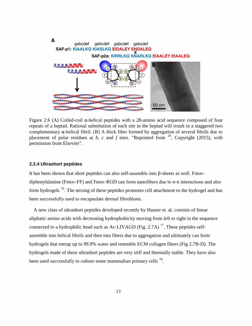
Figure 2.6 (A) Coiled-coil α-helical peptides with a 28-amino acid sequence composed of four
repeats of a heptad. Rational substitution of each site in the heptad will result in a staggered two
complementary α-helical fibril. (B) A thick fiber formed by aggregation of several fibrils due to
placement of polar residues at b, c and f sites. "Reprinted from 20
, Copyright (2015), with permission
from Elsevier". ..................................................................................................................................... 13
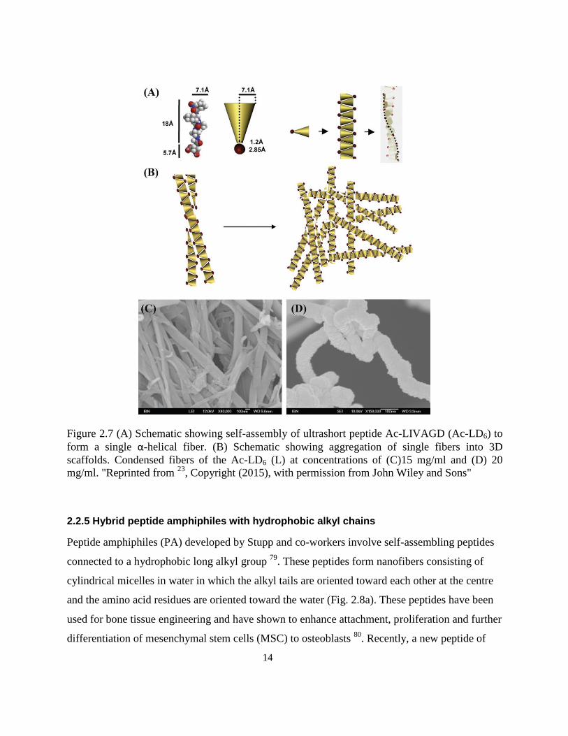
Figure 2.7 (A) Schematic showing self-assembly of ultrashort peptide Ac-LIVAGD (Ac-LD6) to form
a single α-helical fiber. (B) Schematic showing aggregation of single fibers into 3D scaffolds.
Condensed fibers of the Ac-LD6 (L) at concentrations of (C)15 mg/ml and (D) 20 mg/ml. "Reprinted
from 23
, Copyright (2015), with permission from John Wiley and Sons" ............................................ 14
Figure 2.8 (a) Self-assembly of peptide amphiphiles to cylindrical nanofibers and cryo-TEM image of
self-assembled aggregates 82
. (b) Directed MSCs cultured and calcein-stained in aligned PA
xiii
hydrogels. (c) SEM image of aligned PA fibers. (d) SEM image of a cell on aligned structure (inset:
zoom-out image; arrow indicates alignment direction). "Reprinted by permission from Macmillan
Publishers Ltd: [Nature Materials] (81
), copyright (2015)". ................................................................. 15
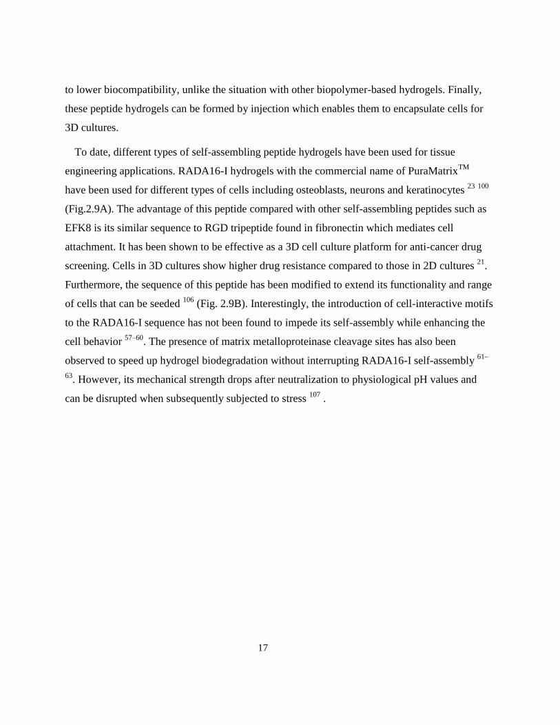
Figure 2.9 (A) Self-assembly of RADA16-I peptide to β-sheet nanofibers which can form hydrogel
with following applications: (i) controlled release of different growth factors, (ii) cell culture substrate
for primary rat hippocampal neurons forming active and functional synapses it, (iii) scaffolds for
endothelial cell migration into mice myocardium (shown by arrows), (iv) scaffolds for neuron
migration and repairing hamster brain lesions. (B) Modification of RADA16-I sequence with
different bioactive motifs and self-assembly to β-sheet nanofibers as well as modification of sequence
with ALK as scaffolds for osteoblast proliferation, differentiation and 3D migration. "Reprinted from
20, Copyright (2015), with permission from Elsevier". ......................................................................... 18
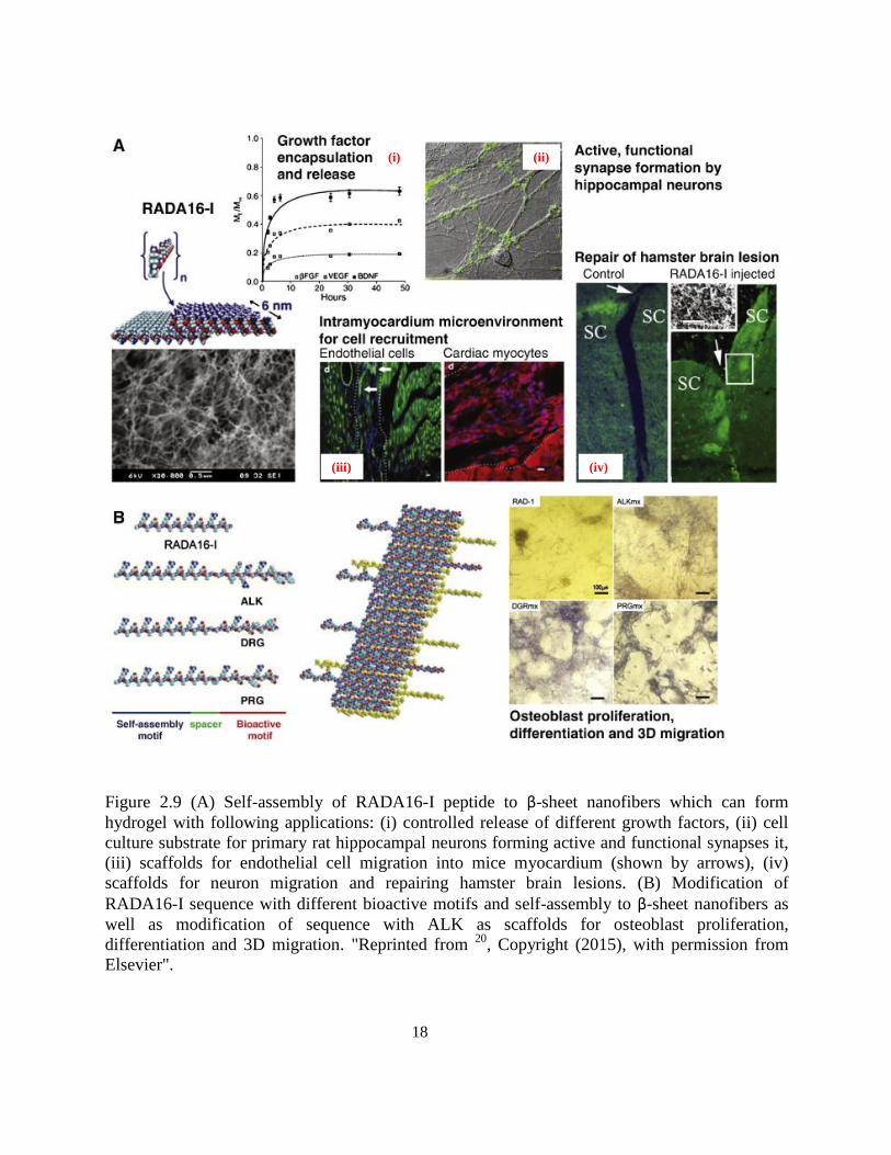
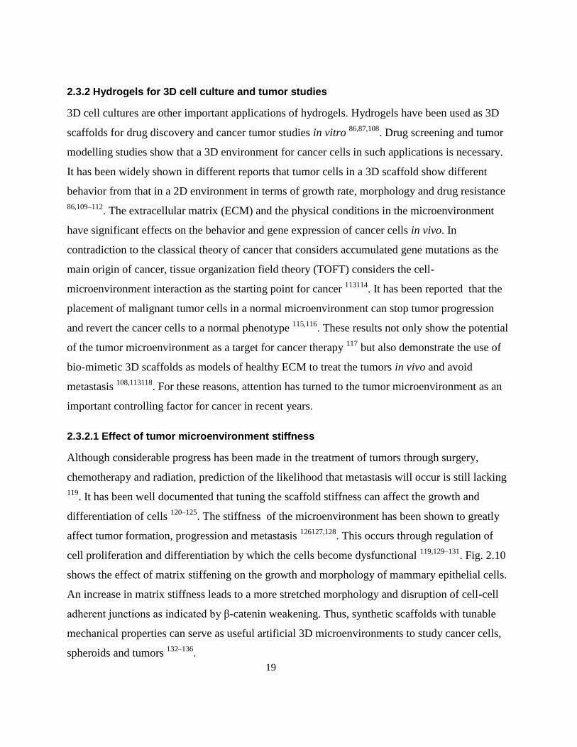
Figure 2.10 Effect of matrix stiffness on mammary epithelial cell (MEC) growth and morphogenesis.
Phase-contrast and confocal images of immunostained 3D MEC colonies after 20 days showing
progressively disrupted colony morphology as matrix stiffness increases (top). Disruption of cell–cell
adherence junctions and luminal clearance with even a modest increase in matrix elastic modulus
(E = 1050 Pa central panel; β-catenin). "Reprinted from 127
., Copyright (2015), with permission from
Springer". .............................................................................................................................................. 20
Figure 2.11 Schematic construction of Hb-graphene-chitosan/GCE. "Reprinted from 181
, Copyright
(2015), with permission from Elsevier". .............................................................................................. 23
Figure 3.1 MWNT probe-sonicated suspensions (a) in water, (b) modified with EFK16-II in water, (c)
in ethanol. Supernatant after centrifugation of MWNT suspensions (d) unmodified in water
immediately after centrifugation, (e) modified with EFK16-II in water; 6 months after centrifugation,
(f) unmodified in ethanol immediately after centrifugation, (g) unmodified in ethanol 4 days after
centrifugation. ....................................................................................................................................... 32
Figure 3.2 Different peptide-MWNT suspensions after centrifugation at 6k g; (a) EFK16-II, (b)
EAK16-II and (c) EK8. ........................................................................................................................ 33
Figure 3.3 (a) Zeta potential and (b) size of EFK16-II-modified MWNTs as a function of pH .......... 35
Figure 3.4 Photographs of EFK16-II-modified MWNT dispersions at different pHs: (a) 2.2, (b) 6.5
and (c) 11.2. All solutions were centrifuged (at 6k×g for 2h) to separate isolated and dispersed
MWNTs from the aggregates before pH adjustment. ........................................................................... 35
Figure 3.5 AFM images of (a) mica surface modified with EFK16-II-modified MWNTs and (b) mica
surface modified with probe-sonicated EFK16-II as a control sample in the absence of MWNTs. Also
xiv
shown are the height profiles (indicated by green lines) across an MWNT in (a) and an EFK16-II
assembly in (b) indicated by an arrow. ................................................................................................ 37
Figure 3.6 (a) SEM image of the surface of HOPG modified with EFK16-II-modified MWNTs and
(b) TEM image of EFK16-II-modified MWNTs on holey carbon grid. .............................................. 38
Figure 3.7 Optical microscopic images of (a) M4A4 GFP and (d) CHO-K1 cells that have attached
and grown for 5 days after seeding in a 24-well tissue culture plate modified with EFK16-II-modified
MWNT; optical images of (b) M4A4 GFP and (e) CHO-K1 cells 5 days after seeding in culture plates
modified with EFK16-II; optical images of (c) M4A4 GFP and (f) CHO-K1 cells 5 days after seeding
in unmodified wells. ............................................................................................................................. 40
Figure 3.8 Photographs of a water droplet on different surfaces: (a) bare plate (contact angle ~ 52°),
(b) plate modified with EFK16-II-modified MWNT (contact angle ~ 14°) and (c) plate modified with
EFK16-II (contact angle ~ 12°). .......................................................................................................... 41
Figure 4.1 EFK8-SWNT dispersion in water: (a) optical image of dispersion in an Eppendorf vial, (b)
TEM image of dried dispersion, (c) AFM image of dried dispersion, (d) high magnification image of
the region shown in (c) and (e) 3-D image of the highlighted region in (d). Inset in bottom left corner
of (c) is a 350 nm2 AFM image of self-assembled EFK8 fibers. ......................................................... 49
Figure 4.2 AFM images of EFK8 peptide fibers: (a) topography, (b) adhesion and (c) modulus maps.
AFM images of EFK8-SWNT fibers: (d) topography, (e) adhesion and (f) modulus maps. Blue dotted
arrow shows a SWNT, while the red arrow shows an EFK8 fiber. Region highlighted in (d) is shown
at higher magnification using (g) topography, (h) adhesion and (i) modulus data .............................. 52
Figure 4.3 EFM images of the EFK8-SWNT dispersion: (a) topography and (b) phase maps showing
the large effect of SWNTs on the phase shift. Higher resolution images of (a) and (b) are shown in (c)
and (d), respectively. ............................................................................................................................ 54
Figure 4.4 (a): EFK8 (left) and EFK8-SWNT hybrid (right) hydrogels. (b) Conceptual diagram of
hybrid hydrogel structure made up of a scaffold (in blue) of peptide fibers containing EFK8-wrapped-
SWNTs. SEM images of (c) EFK8 hydrogel, (d) EFK8-SWNT hydrogels. Highlighted region in (d) is
shown at higher magnification in (e). .................................................................................................. 58
Figure 5.1 NIH-3T3 cells seeded and cultured on EFK8 hydrogel after (a) 1, (b) 3 and (c) 5 days of
seeding and on EFK8-SWNT hybrid hydrogels after (e) 1, (f) 3 and (g) 5 days of seeding (scale bar:
400 m length). Confocal microscopy images of (d) EFK8 and (h) EFK8-SWNT at higher
magnification (scale bar: 20 m length). Cells were stained for f-actin using Actin GreenTM
(green)
xv
and for nuclei with DAPI (blue)). (i) RADA16-I hydrogel disrupted 1 day after seeding the cells
(scale bar: 1000 m length). ................................................................................................................. 70
Figure 5.2 (a-b) NIH-3T3 cell colonies on EFK8 hydrogel at different magnifications. (c-f)
Individually spread cells on the hybrid EFK8-SWNT hydrogel at different magnifications. Cell
protrusions responsible for cell attachment to the scaffold are apparent in (f). ................................... 72
Figure 5.3 NIH-3T3 cell proliferation on the EFK8 and EFK8-SWNT hydrogels incubated for 1, 3
and 5 days after seeding. All data represent mean ± s.d. *P < 0.05. .................................................... 73
Figure 5.4 Optical (a) and confocal (b) microscopy images of an EFK8-SWNT hydrogel embedded in
an EFK8 hydrogel. Z-stack images (c,d) obtained at different angles show the 3-dimensional structure
of the cells within the hybrid hydrogel. ................................................................................................ 75
Figure 5.5 Optical images of EFK8 hydrogel modified with an EFK8-SWNT drop at the center taken
on (a) day 1 and (b) day 3 after seeding. Higher magnification images (c-q) of the SWNT-containing
region taken at 1-hour intervals. The arrows indicate cells or colonies that may be migrating toward
the EFK-SWNT region. ........................................................................................................................ 76
Figure 5.6 (a) EFK8 hydrogel patterned with EFK8-SWNT hydrogels observed at (a) lower and (b)
higher magnifications. .......................................................................................................................... 77
Figure 5.7 3D encapsulated cells 1, 3 and 5 days after encapsulation in EFK8 (a-c) and EFK8-SWNT
(d-f) hydrogels, respectively. ................................................................................................................ 79
Figure 5.8 Optical images of cell drops formed in EFK8 (a: day 1, b: day 5 and c: 2 weeks) and
EFK8-SWNT (d: day 1, e: day 5 and f: 2 weeks) hydrogels. ............................................................... 80
Figure 5.9 3D cell migration in the mixed hydrogel rods. EFK8-SWNT hydrogel rod with a small
cell-containing EFK8 hydrogel head after day (a) 1 and (b) 11, respectively. EFK8 hydrogel rod with
a small cell-containing EFK8-SWNT hydrogel head after day (d) 1 and (e) 11, respectively. (c)
EFK8-SWNT part of the rod at a larger distance from the head in (b). (f) EFK8 part of the rod at a
larger distance from the head in (e). ..................................................................................................... 82
Figure 5.10 (a) Compressive modulus of various hydrogels. (b) Optical image of NIH-3T3 cells after
5 days of seeding on EFK8 hydrogel formed from peptide at concentration 5 mg ml−1
. All data
represent mean ± s.d. *P < 0.05. .......................................................................................................... 83
Figure 5.11 Optical images showing the evolution of A549 lung cancer cells seeded on different
hydrogels. Left column: Formation of spheroidal colonies of cancer cells induced by seeding on an
EFK8 hydrogel formed from 1.25 mg ml−1
peptide. Middle column: Evidence of cancer cell migration
after seeding on EFK8 hydrogel formed from 5 mg ml−1
peptide. Right column: Evidence of cancer
xvi
cell migration after seeding on EFK8-SWNT hybrid hydrogel formed from 1.25 mg ml−1
peptide.
Scale bar is 200 μm. ............................................................................................................................. 84
Figure 5.12 Morphological staining of A549 lung cancer cells using Live/Dead® assay reagent on (a)
EFK8 hydrogel and (b) EFK8 (5 mg ml−1
) hydrogel (live cells are green and dead ones are red). A549
cells immunostained for β-catenin (green) and nucleus (blue). Immunostaining of the same cells on
(c) EFK8, (d) EFK8 (5 mg ml−1
) and (e) EFK8-SWNT hydrogels. Scale bar corresponds to 20 m
length. .................................................................................................................................................. 86
Figure 6.1 CVs obtained on bare GCE, GCE modified with EFK8 and GCE modified with EFK8-
SWNT in 1M KCl containing 10 mM K3Fe(CN)6 at a scan rate of 100 mV/s. ................................... 94
Figure 6.2 (a) Nyquist plots obtained on bare GCE, EFK8-modified GCE and EFK8-SWNT-modified
GCE over a frequency range of 1 mHz − 100 kHz in 10 mM K3Fe(CN)6 dissolved in 1M KCl
electrolyte. (b) Nyquist plot at higher frequencies. .............................................................................. 95
Figure 6.3 (a) Effect of scan rate on the cathodic and anodic peak currents of Fe(CN)63−
/Fe(CN)64−
couple on an EFK8-SWNT modified electrode. (b) Traces of the CV responses over 50 cycles. (c)
Effect of the number of EFK8-SWNT hybrid layers on the CVs obtained at a scan rate of 100 mV/s in
1M KCl containing 10 mM K3Fe(CN)6. .............................................................................................. 97
Figure 6.4 (a) Top view of EFK8-SWNT coating. (b) Top view of coating after removal from the
GCE surface, showing the crack that had developed. (c) Higher magnification of (b) showing the
fibrous structure of the coating. ........................................................................................................... 98
Figure 6.5 (a) CV and (b) Nyquist plots obtained on bare GCE, EFK8-SWNT and EFK8-SWNT-Hb-
modified GCE immersed in 1M KCl containing 10mM K3Fe(CN)6. .................................................. 99
Figure 6.6 (a) CVs obtained on mediatorless EFK8-SWNT and EFK8-SWNT-Hb modified GCE in
0.1M PBS. (b) Effect of scan rate on CVs obtained on mediatorless EFK8-SWNT-Hb modified GCE
in 0.1M PBS. ...................................................................................................................................... 100
Figure 6.7 CVs of EFK8-SWNT-Hb-modified GCE in 0.1M PBS (pH:7.0) obtained at different H2O2
concentrations. ................................................................................................................................... 102
Figure 6.8 (a) Amperometric calibration curve of EFK8-SWNT-Hb-modified GCE at different H2O2
concentrations acquired at −1.0V after 10s. (b) Linear part of the graph. (c) Lower concentrations of
the linear part. .................................................................................................................................... 103
1
Chapter 1
Introduction
1.1 Overview
In the past two decades, nanotechnology has emerged as a major multidisciplinary field of
knowledge that combines different aspects of science and engineering. Nanomaterials play a key
role in expanding nanotechnology in our everyday life. Due to the similarity in their sizes to that
of biological molecules, nanomaterials have made a significant effect in medicine 12
. Biomedical
applications of nanomaterials range from drug delivery and tissue engineering to visualization
and biosensors. However, the toxicity of nanomaterials is a major issue that must be faced for
each bio-application. Thus, nanomaterials are often functionalized with biomolecules to enable
safer interaction in both in vitro and in vivo systems 3.
From their discovery in 1991 4, carbon nanotubes (CNTs) have been the subject of extensive
research in various fields of science and engineering for different types of applications due to
their multifunctional nature and unusual properties 5. These materials have the highest strength
and stiffness yet discovered, with a hardness greater than that of diamond, an electrical
conductivity more than 1000 times greater than that of copper and thermal conductivity about 10
times better than that of copper. Obviously, these properties make CNTs very attractive for
incorporation into many systems 6789
. On the other hand, strong van der Waals forces between
individual CNTs cause them to readily aggregate, something which hampers their handling and
usage. Consequently, different types of modifications classified as being covalent or non-
covalent, have been developed to separate and disperse CNTs in order to more fully realize the
benefits of their unique properties 10
. Since covalent modifications tend to introduce defects into
the CNT structure and degrade their properties, the approach of introducing non-covalent
modifications is usually preferred. Also, since toxicity and biocompatibility are of special
concern for biomedical applications of nanomaterials, non-covalent modification using biological
molecules would be an attractive option for the use of CNTs in such applications 11
. At the same
time, some biological molecules can functionalize CNTs and introduce special properties and
2
provide a template for conjugating further nanoparticles to CNTs, in addition to facilitating their
dispersion 3. Self-assembling peptides are one of the materials that have been explored for this
application 12–17
.
Similar to carbon nanotubes, self-assembling peptides are considered to be multifunctional
nanomaterials. These biomaterials can form supramolecular structures through self-assembly
processes 18
. They have been used as scaffolds for tissue engineering and hydrogels for 3D cell
culture and drug delivery 19–22
. The first generation of these materials was ionic-complementary
peptides which form β-sheet nanofibers in aqueous media. Their sequences can be modified with
functional motifs for specific cell interactions or nanoparticle attachment 2324
. Also, they are
amphiphilic which makes them potentially effective dispersants for hydrophobic nanomaterials
such as anti-cancer drugs 22
. Thus, these peptides should be able to interact with hydrophobic
CNTs if the appropriate sequence is employed. If these ideas are successful, the synergy between
these two multifunctional nanomaterials will enhance the action of each species with regard to
their original purpose. For example, CNTs have been used widely to modify bio-electrode
surfaces and biosensor electrodes 25
. The interaction of these CNTs with self-assembling peptides
not only can functionalize them but also can increase their biocompatibility for biomedical
applications. Meanwhile, while self-assembling peptides are widely used to form hydrogel
scaffolds, the incorporation of CNTs would enhance hydrogel functionality. Consequently, the
research presented in this thesis is first aimed at investigating the interaction of a specific
sequence of self-assembling peptide with both MWNTs and SWNTs. Based on the results
obtained in this first phase, peptide-CNT hybrid dispersions are prepared and used for several
applications: composite hydrogels for tissue engineering and 3D cell cultures and modification of
a model biosensor electrode.
1.2 Objectives
The objective of this research is to modify and disperse carbon nanotubes using the EFK family
of ionic-complementary self-assembling peptides. If successful, the prepared dispersions will be
employed first to explore the possibility of making a hybrid hydrogel and its application in tissue
3
engineering and next to enhance the electrochemical response of a glassy carbon electrode for
use as a model hydrogen peroxide biosensor. The detailed objectives are as follows:
1. Dispersion of multi-walled carbon nanotubes in water using EFK16-II peptide and assessing
the attachment and growth of normal and cancer cells on plates modified with this dispersion.
2. Dispersion of single-walled carbon nanotubes in water using EFK8 and investigation of the
peptide-SWNT interactions. This study is extended to investigate the possibility of forming
hybrid EFK8-SWNT hydrogels.
3. Exploration of the possibility of using the hybrid peptide-SWNT hydrogels for tissue
engineering and 3D cell cultures.
4. Investigation of the use of the hybrid dispersion to modify glassy carbon electrodes for
application as an electrochemical H2O2 biosensor.
1.3 Outline of thesis
This thesis includes seven chapters: introduction, literature review, 4 research chapters followed
by conclusions and recommendations.
Chapter 1 opens with an introduction of the thesis including a brief review of carbon nanotubes,
self-assembling peptide and their applications. Also the research objectives and thesis outline are
given.
Chapter 2 includes a literature review of carbon nanotube dispersions, different types of self-
assembling peptides and their applications. Also, the use of hydrogels in tissue engineering and
3D cancer tumor research and previous studies on mediatorless electrochemical biosensors are
reviewed.
Chapter 3 reports on the dispersion of MWNTs using the self-assembling peptide EFK16-II. Also
the resulting dispersions are characterized and the individual dispersion of MWNTs is confirmed.
Finally, experiments concerned with the attachment and growth of cells on tissue culture plates
modified with the peptide-MWNT dispersion are discussed.
4
Chapter 4 focuses on the interaction between EFK8 and SWNTs using scanning probe
microscopy (SPM) techniques to distinguish peptide fibers from SWNTs. Also, the possibility of
forming peptide-SWNT hybrid hydrogels is reported for the first time.
Chapter 5 explores the application of hybrid EFK8-SWNT hydrogels for tissue engineering and
the effect of SWNTs on the properties and effectiveness of the hydrogels. Also, the potential of
EFK8 hydrogels and hybrid EFK8-SWNT hydrogels for use in studying the effect of
microenvironment on tumors is examined.
Chapter 6 considers the application of hybrid EFK8-SWNT dispersions to modify the surface of
glassy carbon electrodes and enhance their electrochemical response. Based on these results, the
modified electrode is used to immobilize hemoglobin and form the basis of a biosensor for
hydrogen peroxide. The sensitivity, linear range and the stability of this biosensor are then
evaluated.
The main findings and contributions of this research are summarized in Chapter 7. Also included
are recommendations for future work in this area.
5
Chapter 2
Literature Review
2.1 Carbon nanotubes for biomedical applications
Since the discovery of carbon nanotubes (CNTs) in 19914, considerable interest has been shown
in incorporating them in chemical sensors, biochemical sensors and nano-scale electronic devices
and utilizing them for tissue engineering applications due to their excellent electronic and
mechanical properties. CNT-modified electrodes have higher electronic conductivity than
graphite-based ones and have been shown to perform better and be more sensitive than those
based on single metals such as Au, Pt and carbon-based nanomaterials such as C60 and C70 25–29
.
Their electronic properties give CNT electrodes the ability to mediate electron transfer reactions
with electroactive species in solution. To date, CNT-based electrodes have been widely used in
electrochemical sensing 11,25,26,29,30
. Furthermore, they are capable of providing suitable interfaces
for the signal transfer and neurite outgrowth of neurons as well as supporting the attachment and
growth of osteoblast, fibroblast and cardiac cells 28
. They have also shown great promise for
applications in tissue engineering by enhancing the properties of biomaterials 27,28,31–42
.
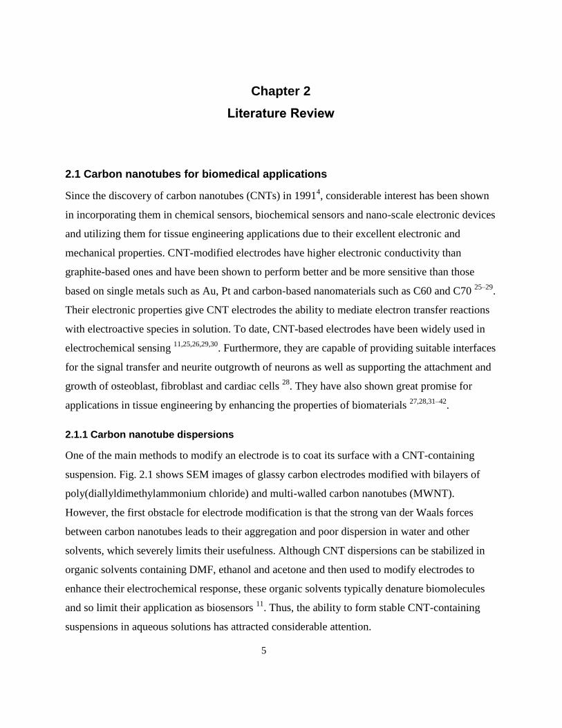
2.1.1 Carbon nanotube dispersions
One of the main methods to modify an electrode is to coat its surface with a CNT-containing
suspension. Fig. 2.1 shows SEM images of glassy carbon electrodes modified with bilayers of
poly(diallyldimethylammonium chloride) and multi-walled carbon nanotubes (MWNT).
However, the first obstacle for electrode modification is that the strong van der Waals forces
between carbon nanotubes leads to their aggregation and poor dispersion in water and other
solvents, which severely limits their usefulness. Although CNT dispersions can be stabilized in
organic solvents containing DMF, ethanol and acetone and then used to modify electrodes to
enhance their electrochemical response, these organic solvents typically denature biomolecules
and so limit their application as biosensors 11
. Thus, the ability to form stable CNT-containing
suspensions in aqueous solutions has attracted considerable attention.
6
Figure 2.1. SEM images of a (A) single layer, (B) three layers and (C) five layers of
{PDDA/MWNT} assembled on a silicon wafer. The scale bars in A-C correspond to a 5 μm
length. SEM image of (A) at higher resolution appears in (D) (scale bar corresponds to 1 μm
length). "Reprinted (adapted) with permission from 43
. Copyright (2015) American Chemical
Society."
Although covalent stabilization of CNTs (using a method such as acid treatment) can
successfully produce such suspensions, this approach has its problems since it tends to diminish
the excellent optical and electronic character of CNTs and impede their inherent conductivity.
Consequently, the formation of suspensions by non-covalent stabilization of CNTs may be a
more promising method. For this purpose, the modification of CNTS by polymers and surfactants
has been studied 44
. When polymers or non-ionic surfactants are used, a CNT suspension can be
successfully dispersed through steric stabilization by an adsorbed surfactant or polymer layer.
The hydrophobic part of the surfactant makes contact with the CNTs, while its hydrophilic part is
oriented toward the solution. When ionic surfactants adsorb onto CNTs, electrostatic repulsion
7
between their similarly charged ends is the dominant factor, impeding nanotube aggregation and
stabilizing the suspensions 44
.
2.1.2 Peptide-based CNT dispersions
The use of peptide-based molecules has been explored as an option for dispersion of CNTs. The
association of CNTs with peptides is expected to be useful in biosensor and tissue engineering
applications and in the development of new bioactive nanomaterials. The biological potential of
carbon nanotubes in immunology was investigated by Pantarotto et al. 12
who demonstrated
enhanced in vivo antibody response from covalently linked nanotube-peptide conjugates. Toward
this end, peptide sequences using phage display with specific affinities for carbon nanotubes
have been identified 1314
. These peptides contain sequences rich in histidine and tryptophan at
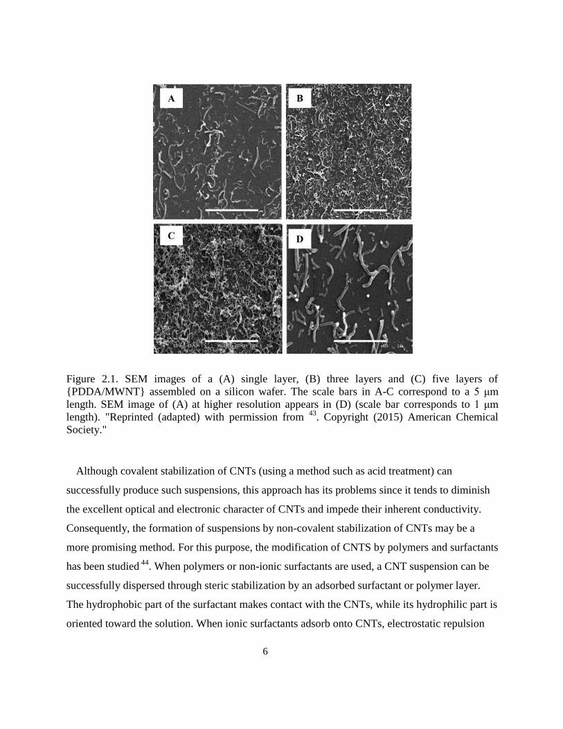
specific locations. Also, nanotubes have been successfully dispersed in aqueous solutions by pre-
treating with amphiphilic peptide sequences which contain phenylalanine at specific locations
(Fig. 2.2) and can fold into α-helixes on nanotube sidewalls 1516
. The main interaction responsible
for suspending carbon nanotubes in water is reported to be π-π stacking between the aromatic
rings in the amino acids and the nanotubes.
Figure 2.2 AFM images of (a) nano-1/SWNT dispersion revealing many long SWNTs, (b)
SDS/SWNT exhibiting minimal dispersion of SWNTs and (c) nano-1 control sample lacking
SWNTs (note: nano-1 is a 29-residue peptide). "Reprinted (adapted) with permission from 16
.
Copyright (2015) American Chemical Society."
8
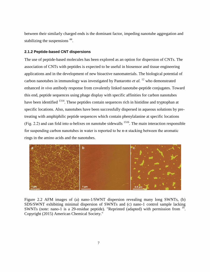
2.1.2.1 Self-assembling peptides for CNT dispersion
Arnold et al. 17
investigated an approach utilizing peptide amphiphile (PA) molecules whereby
amino acid sequences are covalently coupled to a hydrophobic alkyl tail. Since the surface of
carbon nanotubes is non-polar and hydrophobic, peptide amphiphiles in an aqueous solution are
expected to self-assemble on this surface and thereby minimize the interfacial energy of the
nanotube-water interface through hydrophobic interaction between the tail and the carbon
nanotubes and as a result expose the hydrophilic sequence to the water (Fig. 2.3). This approach
has several potential benefits. First, due to the non-covalent assembly of peptide amphiphiles, the
nanotube sidewalls should not be chemically modified and so should maintain their outstanding
electrical, mechanical and optical properties. Second, the hydrophobic tail of the peptide
amphiphile is expected to interact with the hydrophobic nanotube surface and leave the peptide
sequence exposed on the exterior for sensing or other biological applications. Furthermore, the
water solubility of nanotubes biofunctionalized with peptide amphiphiles should be controllable
by adjusting the pH since this affects the net charge of peptide segments and the resulting ionic
repulsion among nanotubes in solution. Finally, this approach is expected to be generally useful
for either positively or negatively charged peptide sequences without the need to incorporate
sequences that specifically bind to nanotube surfaces.
Figure 2.3 TEM micrographs of MWNTs with anionic PA at (A) low magnification (scale bar
corresponds to 50 nm) and (B) high magnification (scale bar corresponds to 10 nm length).
MWNTs are highlighted in red and the surrounding coating is indicated in blue. "Reprinted
(adapted) with permission from 17
. Copyright (2015) American Chemical Society."
9
2.2 Self-assembling peptides
The thermodynamically driven spontaneous arrangement of molecules to form stable ordered
structures via non-covalent interactions is called molecular self-assembly 45
. From the discovery
of the first self-assembling peptide EAK16-II by Zhang et al. in 1993, a considerable amount of
attention has been focused on this type of nano-biomaterial as a promising option for a wide
range of biomedical applications such as anti-cancer drug delivery, biocompatible hydrogels as
scaffolds for 3D cell cultures, tissue engineering and wound healing (hemostasis) 19,22,46–52
.
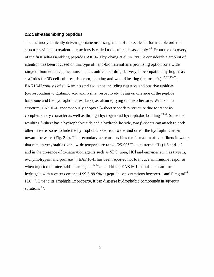
EAK16-II consists of a 16-amino acid sequence including negative and positive residues
(corresponding to glutamic acid and lysine, respectively) lying on one side of the peptide
backbone and the hydrophobic residues (i.e. alanine) lying on the other side. With such a
structure, EAK16-II spontaneously adopts a -sheet secondary structure due to its ionic-
complementary character as well as through hydrogen and hydrophobic bonding 5053
. Since the
resulting -sheet has a hydrophobic side and a hydrophilic side, two -sheets can attach to each
other in water so as to hide the hydrophobic side from water and orient the hydrophilic sides
toward the water (Fig. 2.4). This secondary structure enables the formation of nanofibers in water
that remain very stable over a wide temperature range (25-90°C), at extreme pHs (1.5 and 11)
and in the presence of denaturation agents such as SDS, urea, HCl and enzymes such as trypsin,
α-chymotrypsin and pronase 54
. EAK16-II has been reported not to induce an immune response
when injected in mice, rabbits and goats 5055
. In addition, EAK16-II nanofibers can form
hydrogels with a water content of 99.5-99.9% at peptide concentrations between 1 and 5 mg ml−1
H2O 19
. Due to its amphiphilic property, it can disperse hydrophobic compounds in aqueous
solutions 56
.
10
Figure 2.4 Amino acid sequences of four peptides containing EAK16-II, β-sheets and the
resulting nanofibrous hydrogels of RADA16-II. "Reprinted from 20
, Copyright (2015), with
permission from Elsevier".
Several types of self-assembling peptides exist. The structure and characteristics of these
peptides are described in the following subsections.
2.2.1 β-sheet forming self-assembling peptides
EAK16-II is the first member of this peptide family. As described previously, due to electrostatic
interactions (ionic-complementarity), hydrogen bonding and hydrophobic interactions, these
peptides assume a β-sheet secondary structure and form ordered nanofibers. Several other
peptides similar to EFK16-II have been designed in order to form 3D scaffolds. Among these,
RADA16-I with the commercial name of PuramatrixTM
is the most popular one. RADA16-I
hydrogels with a fiber size of 10-20 nm in diameter have been shown to support neurite
outgrowth similar to the level on Matrigel and exhibit no toxicity to rats after 5 weeks of
exposure. Due to these promising results, RADA16-based hydrogels have been used for a diverse
range of cells and tissues including osteoblasts, neurons and keratinocytes 23
. They have been
shown to be effective as 3D cell culture platforms for anti-cancer drug screening. Cells seeded in
such 3D systems show higher drug resistance compared to 2D cultures 21
. Interestingly, the
introduction of cell-interactive motifs to the RADA16 sequence does not impede its self-
assembly while enhancing cell behavior 57–60
. The introduction of matrix metalloproteinase
cleavage sites has also been observed to speed up hydrogel biodegradation without interrupting
11
the RADA16 self-assembly 61–63
. By replacing the hydrophobic amino acids in the sequences of
these peptides (i.e. alanine) with more hydrophobic ones, the hydrophobic interactions become
stronger and the critical concentration for β-sheet formation is reduced. Reduction of the number
of amino acids from 16 to 8 is also shown to decrease the critical gelation concentration 6465
.
KLD12 is another β-sheet forming peptide which has been used as a scaffold for chondrocyte
encapsulation that is biocompatible with rabbit mesenchymal stem cells and nucleus pulposus
cells 23
.
2.2.2 β-hairpin forming peptides
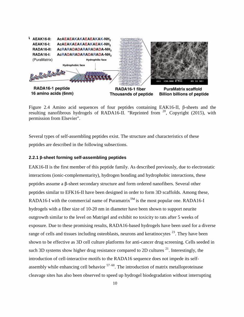
β-hairpin peptides consist of two β-strands connected to each other via a kink and can form
nanofibers. For example, MAX1 (VKVKVKVKVDPPTKVKVKVKV-NH2) and MAX8
(VKVKVKVKVDPPTKVEVKVKV-NH2) are two β-hairpin peptides consisting of two series of
alternating valine and lysine amino acids connected by a VDPPT tetrapeptide working as a β-turn
6667. These peptides have a random coil structure which can spontaneously form a β-hairpin
structure when the temperature is raised. These peptides interact with each other through
hydrogen bonding and van der Waals forces and self-assemble laterally. Also, due to
hydrophobic interactions between their hydrophobic faces, they form bilayers as shown in Fig.
2.5. Although neither of these peptides showed an immune response in vitro 68
, MAX1 was not
able to encapsulate C3H10t1/2 mesenchymal cells due to slow gelation, whereas MAX8 was able
to homogeneously encapsulate the cells 69
. A very interesting characteristic of these peptides is
that they undergo shear-thinning. Thus, their viscosity decreases and they begin to flow when
subject to a shear stress, but can revert to their previous rigid structure when the stress is
removed. This capability enables them to be injected via syringes. Experiments have shown that
cells delivered using this method are able to maintain their viability during shear thinning 6970
.
This class of peptides has been further developed to be responsive to light or change in pH and
ionic strength 20
.
12
Figure 2.5 (A) Folding of peptides to form β-hairpin structure and self-assembly of β-hairpins
through lateral (hydrogen bonding and van der Waals interaction) and facial (hydrophobic
interaction) association. (B) Amino acid sequences of MAX1 and MAX8 β-hairpin peptides.
"Reprinted from 68
, Copyright (2015), with permission from Elsevier".
2.2.3 α-helical peptides
α-helical coiled-coil peptides developed by Woolfson et al. are another class of peptides forming
self-assembling fibers (SAFs) 71–75
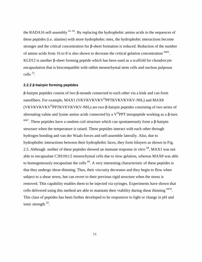
. SAFs consist of two 28-amino acid sequences containing
repeats of a coiled-coil heptad sequence (gPaHbPcPdHePfP)n , in which H stands for a hydrophobic
amino acid and P for a polar amino acid (Fig. 2.6A). In this heptad sequence, hydrophobic amino
acids isoleucine and leucine in the a and d positions, respectively, introduce an inter-helical
hydrophobic interaction that facilitates dimerization. The insertion of asparagine residues (which
preferentially interact with each other) at some specific a positions stabilizes the dimerization.
Opposite charges at the e and g positions help the two coiled-coil peptides to twist and form
parallel fibrils. b, c and f sites can be occupied by polar residues that facilitate electrostatic fibril
aggregations and enable fibers to form (Fig. 2.6B) or by residues with hydrophobic or hydrogen-
bond interactions that yield thinner fibers with more flexibility. Experiments have shown that the
hydrogel can support growth and differentiation of PC12 cells for sustained periods in cultures 74
.
However, large-scale production of long peptides for various applications remains a challenge 23
.
13
Figure 2.6 (A) Coiled-coil α-helical peptides with a 28-amino acid sequence composed of four
repeats of a heptad. Rational substitution of each site in the heptad will result in a staggered two
complementary α-helical fibril. (B) A thick fiber formed by aggregation of several fibrils due to
placement of polar residues at b, c and f sites. "Reprinted from 20
, Copyright (2015), with
permission from Elsevier".
2.2.4 Ultrashort peptides
It has been shown that short peptides can also self-assemble into β-sheets as well. Fmoc-
diphenylalanine (Fmoc-FF) and Fmoc-RGD can form nanofibers due to π-π interactions and also
form hydrogels 76
. The mixing of these peptides promotes cell attachment to the hydrogel and has
been successfully used to encapsulate dermal fibroblasts.
A new class of ultrashort peptides developed recently by Hauser et. al. consists of linear
aliphatic amino acids with decreasing hydrophobicity moving from left to right in the sequence
connected to a hydrophilic head such as Ac-LIVAGD (Fig. 2.7A) 77
. These peptides self-
assemble into helical fibrils and then into fibers due to aggregation and ultimately can form
hydrogels that entrap up to 99.9% water and resemble ECM collagen fibers (Fig 2.7B-D). The
hydrogels made of these ultrashort peptides are very stiff and thermally stable. They have also
been used successfully to culture some mammalian primary cells 78
.
14
Figure 2.7 (A) Schematic showing self-assembly of ultrashort peptide Ac-LIVAGD (Ac-LD6) to
form a single α-helical fiber. (B) Schematic showing aggregation of single fibers into 3D
scaffolds. Condensed fibers of the Ac-LD6 (L) at concentrations of (C)15 mg/ml and (D) 20
mg/ml. "Reprinted from 23
, Copyright (2015), with permission from John Wiley and Sons"
2.2.5 Hybrid peptide amphiphiles with hydrophobic alkyl chains
Peptide amphiphiles (PA) developed by Stupp and co-workers involve self-assembling peptides
connected to a hydrophobic long alkyl group 79
. These peptides form nanofibers consisting of
cylindrical micelles in water in which the alkyl tails are oriented toward each other at the centre
and the amino acid residues are oriented toward the water (Fig. 2.8a). These peptides have been
used for bone tissue engineering and have shown to enhance attachment, proliferation and further
differentiation of mesenchymal stem cells (MSC) to osteoblasts 80
. Recently, a new peptide of
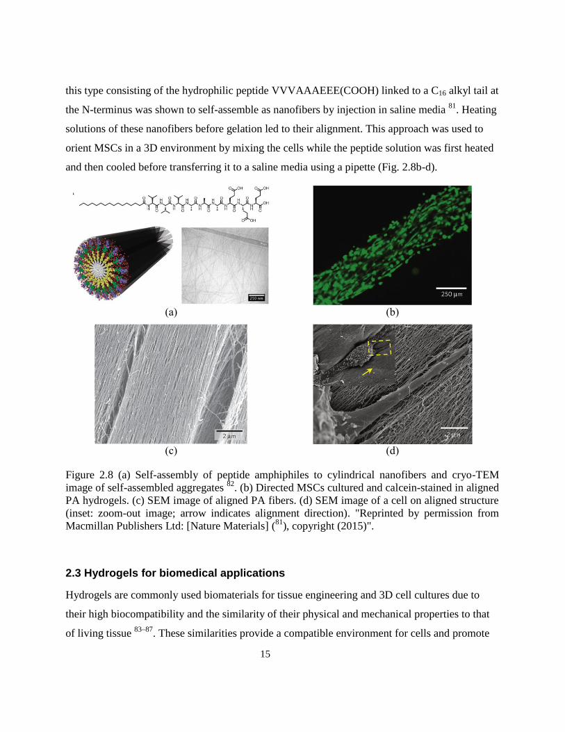
15
this type consisting of the hydrophilic peptide VVVAAAEEE(COOH) linked to a C16 alkyl tail at
the N-terminus was shown to self-assemble as nanofibers by injection in saline media 81
. Heating
solutions of these nanofibers before gelation led to their alignment. This approach was used to
orient MSCs in a 3D environment by mixing the cells while the peptide solution was first heated
and then cooled before transferring it to a saline media using a pipette (Fig. 2.8b-d).
(a)
(b)
(c)
(d)
Figure 2.8 (a) Self-assembly of peptide amphiphiles to cylindrical nanofibers and cryo-TEM
image of self-assembled aggregates 82
. (b) Directed MSCs cultured and calcein-stained in aligned
PA hydrogels. (c) SEM image of aligned PA fibers. (d) SEM image of a cell on aligned structure
(inset: zoom-out image; arrow indicates alignment direction). "Reprinted by permission from
Macmillan Publishers Ltd: [Nature Materials] (81
), copyright (2015)".
2.3 Hydrogels for biomedical applications
Hydrogels are commonly used biomaterials for tissue engineering and 3D cell cultures due to
their high biocompatibility and the similarity of their physical and mechanical properties to that
of living tissue 83–87
. These similarities provide a compatible environment for cells and promote
16
behavior to be similar to that observed in vivo. Hydrogels can also be modified chemically to
mimic living tissues that makes them more biocompatible and perform better in the body 83–85,88
.
2.3.1 Hydrogel scaffolds for tissue engineering
Different types of materials have been used to date to make hydrogel scaffolds for different types
of tissues. These include synthetic materials such as polylactic acid (PLA) 8990
, polyethylene
oxide (PEO) 91
, polyglycolic acid (PGA) 92
, polyvinyl alcohol (PVA) 9394
, polyethylene glycol
(PEG) 95
, as well as polysaccharide hydrogels consisting of hyaluronic acid (HA) 96
, chitosan 97
,
agarose 98
and alginate 99
. Production of these synthetic polymers is reproducible which makes
them attractive for researchers. However, hydrogels formed this way have major drawbacks such
as large fiber/pore sizes, the use of toxic reagents for gel formation, low degradation under
physiological conditions, improper charge density, low nutrient diffusion rate and the formation
of acidic products due to degradation 100
. On the other hand, protein-based hydrogels using
collagen 101
, gelatin 102
, fibrin 103
, elastin 104
, silk fibroin 105
and MatrigelTM
are more
biocompatible and biodegradable and provide a better platform for cell attachment and growth.
However, they suffer from batch-to-batch variations and unwanted contaminants such as growth
factors, proteins and viruses which can interfere with cell function 83,100
.
2.3.1.1 Self-assembling peptide hydrogels
Based on the above-mentioned considerations, the best option would be to use a natural synthetic
material. Self-assembling peptides are very promising from this point of view. Although they are
formed from amino acids, can be found throughout the body ubiquitously, they can also be
synthesized with precise control of its chemical composition. This should minimize the effects of
contaminants and enable the effects of different cues on cell behavior in the prepared scaffold to
be clearly distinguished. Their biodegradation products are natural amino acids that are used in
the body and can be functionalized with different bioactive motifs for different cells and tissues.
Also, nano-sized fibers and pores of hydrogels formed from these peptides resemble the structure
of living tissues in the body. This provides an environment that closely mimics in-vivo cell-cell
and cell-scaffold interactions. In addition, fiber crosslinking by which hydrogels form from these
peptides does not require any chemical additives, UV irradiation or heat treatment which can lead
17
to lower biocompatibility, unlike the situation with other biopolymer-based hydrogels. Finally,
these peptide hydrogels can be formed by injection which enables them to encapsulate cells for
3D cultures.
To date, different types of self-assembling peptide hydrogels have been used for tissue
engineering applications. RADA16-I hydrogels with the commercial name of PuraMatrixTM
have been used for different types of cells including osteoblasts, neurons and keratinocytes 23
100
(Fig.2.9A). The advantage of this peptide compared with other self-assembling peptides such as
EFK8 is its similar sequence to RGD tripeptide found in fibronectin which mediates cell
attachment. It has been shown to be effective as a 3D cell culture platform for anti-cancer drug
screening. Cells in 3D cultures show higher drug resistance compared to those in 2D cultures 21
.
Furthermore, the sequence of this peptide has been modified to extend its functionality and range
of cells that can be seeded 106
(Fig. 2.9B). Interestingly, the introduction of cell-interactive motifs
to the RADA16-I sequence has not been found to impede its self-assembly while enhancing the
cell behavior 57–60
. The presence of matrix metalloproteinase cleavage sites has also been
observed to speed up hydrogel biodegradation without interrupting RADA16-I self-assembly 61–
63. However, its mechanical strength drops after neutralization to physiological pH values and
can be disrupted when subsequently subjected to stress 107
.
18
Figure 2.9 (A) Self-assembly of RADA16-I peptide to β-sheet nanofibers which can form
hydrogel with following applications: (i) controlled release of different growth factors, (ii) cell
culture substrate for primary rat hippocampal neurons forming active and functional synapses it,
(iii) scaffolds for endothelial cell migration into mice myocardium (shown by arrows), (iv)
scaffolds for neuron migration and repairing hamster brain lesions. (B) Modification of
RADA16-I sequence with different bioactive motifs and self-assembly to β-sheet nanofibers as
well as modification of sequence with ALK as scaffolds for osteoblast proliferation,
differentiation and 3D migration. "Reprinted from 20
, Copyright (2015), with permission from
Elsevier".
(i) (ii)
(iii) (iv)
19
2.3.2 Hydrogels for 3D cell culture and tumor studies
3D cell cultures are other important applications of hydrogels. Hydrogels have been used as 3D
scaffolds for drug discovery and cancer tumor studies in vitro 86,87,108
. Drug screening and tumor
modelling studies show that a 3D environment for cancer cells in such applications is necessary.
It has been widely shown in different reports that tumor cells in a 3D scaffold show different
behavior from that in a 2D environment in terms of growth rate, morphology and drug resistance
86,109–112. The extracellular matrix (ECM) and the physical conditions in the microenvironment
have significant effects on the behavior and gene expression of cancer cells in vivo. In
contradiction to the classical theory of cancer that considers accumulated gene mutations as the
main origin of cancer, tissue organization field theory (TOFT) considers the cell-
microenvironment interaction as the starting point for cancer 113114
. It has been reported that the
placement of malignant tumor cells in a normal microenvironment can stop tumor progression
and revert the cancer cells to a normal phenotype 115,116
. These results not only show the potential
of the tumor microenvironment as a target for cancer therapy 117
but also demonstrate the use of
bio-mimetic 3D scaffolds as models of healthy ECM to treat the tumors in vivo and avoid
metastasis 108,113118
. For these reasons, attention has turned to the tumor microenvironment as an
important controlling factor for cancer in recent years.
2.3.2.1 Effect of tumor microenvironment stiffness
Although considerable progress has been made in the treatment of tumors through surgery,
chemotherapy and radiation, prediction of the likelihood that metastasis will occur is still lacking
119. It has been well documented that tuning the scaffold stiffness can affect the growth and
differentiation of cells 120–125
. The stiffness of the microenvironment has been shown to greatly
affect tumor formation, progression and metastasis 126127,128
. This occurs through regulation of
cell proliferation and differentiation by which the cells become dysfunctional 119,129–131
. Fig. 2.10
shows the effect of matrix stiffening on the growth and morphology of mammary epithelial cells.
An increase in matrix stiffness leads to a more stretched morphology and disruption of cell-cell
adherent junctions as indicated by β-catenin weakening. Thus, synthetic scaffolds with tunable
mechanical properties can serve as useful artificial 3D microenvironments to study cancer cells,
spheroids and tumors 132–136
.
20
Figure 2.10 Effect of matrix stiffness on mammary epithelial cell (MEC) growth and
morphogenesis. Phase-contrast and confocal images of immunostained 3D MEC colonies after
20 days showing progressively disrupted colony morphology as matrix stiffness increases (top).
Disruption of cell–cell adherence junctions and luminal clearance with even a modest increase in
matrix elastic modulus (E = 1050 Pa central panel; β-catenin). "Reprinted from 127
., Copyright
(2015), with permission from Springer".
2.3.3 Hybrid hydrogels with CNTs
Due to their remarkable electronic and mechanical properties, carbon nanotubes have been
incorporated into hydrogels to modify their physical and mechanical properties for a variety of
tissue applications 137–144
. In the past few years, the incorporation of CNTs in collagen hydrogels
has been shown to increase the electrical conductivity of the hydrogels and to enable better
control of their mechanical properties 145–152
. Conductive hydrogels are useful for mimicking and
regenerating tissues in which electrical signals are propagated such as in cardiac muscles and
neural tissue 139,141–143,148,149,151–153
. At the same time, it has been shown that the mechanical
properties of the scaffold play a major role in the behavior and fate of cells, particularly stem
21
cells 120,122,125,154
. This opens up the possibility of using soft hydrogels for a wider range of
tissues by using CNT-based scaffolds to improve their mechanical properties.
2.4 Electrochemical biosensors
2.4.1 Mediatorless biosensors
Since the 1970s, direct electron transfer between redox proteins and electrode surfaces and its
application for mediatorless electrochemical biosensors have been extensively studied. The most
efficient method to make a redox protein-based electrochemical biosensor is to establish direct
electron transfer between the protein and electrode. The use of a mediator facilitates not only the
electron transfer between the electrode and enzyme but also various interfering reactions.
Mediatorless biosensors can offer better selectivity since they are able to operate in a potential
range closer to the redox potential of the protein itself and thus make interfering reactions less
likely to occur 155156
. In addition, most in-vivo devices are mediatorless to avoid any possible
leaching of the mediator and consequential toxic effects. Mediated systems also tend to be less
stable during extended continuous operation 157
. Normally direct adsorption of proteins on the
electrode surface leads to their denaturation and loss of their catalytic and electrochemical
activity 158
. Thus, an important first step in designing a mediatorless biosensor is to immobilize
the protein without denaturation.
2.4.2 Hydrogen peroxide biosensors based on hemoglobin
Hemoglobin (Hb) is an important protein in red blood cells as a reversible oxygen carrier in the
body through its four polypeptide chains which contain electroactive heme groups. It has been
reported that Hb also can catalyze the reduction of hydrogen peroxide 159
. The ability to rapidly
and accurately determine hydrogen peroxide concentration is very important since it is the
product of many enzymatic reactions and is also commonly found in food, clinical,
pharmaceutical, industrial and environmental systems 159–161156
. A number of techniques such as
HPLC 161
, titrimetry 162
, spectrometry 163
, chemiluminescence 164
and electrochemical methods
165 are currently available for hydrogen peroxide determination.
22
Electrochemical methods for hydrogen peroxide analysis have attracted extensive interest
because they are fast, less prone to interferences and relatively inexpensive 161
. Basically, two
types of amperometric enzyme-based H2O2 probes can be used − mediated biosensors and
mediatorless biosensors. Although the mediated H2O2 biosensors can detect very low
concentrations by use of electron transfer mediators such as ferrocene derivatives 166
,
hexacyanoferrates 167
, tetrathiafulvalene 168
or phenazine methosulphate 169
, the danger exists that
mediator molecules can contaminate the sample or electrode system or can diffuse from the
enzyme layer 170
. Mediatorless biosensors which operate through the direct electron transfer
between redox proteins and electrode have gained increasing attention because they do not suffer
from this leakage problem and have potentially simpler design without the need for a chemical
mediator.
2.4.3 Direct electron transfer from Hb
In addition to its ability to electrocatalyze H2O2 reduction, Hb is an ideal model protein for the
study of the direct electron transfer of heme molecules due to its commercial availability,
reasonable cost and well-known structure. However, the direct electrochemical reaction of Hb on
an electrode is very difficult for a number of reasons. Since the heme group resides inside the Hb
structure and is surrounded by the protein polypeptide chains, the electrons being transferred
must travel a large distance to the electrode surface and a mediator is often required to help
transport them. Once adsorbed, Hb on the surface frequently denatures and loses its
electrochemical activity and bioactivity. Hb becomes a barrier to electron transfer on the
electrode surface once it becomes denatured 171
. Finally, Hb located at the electrode surface may
not have a favorable orientation for electron transfer. To date, different methods and
nanomaterials including Au, Pt and CdTe nanoparticles as well as graphene (Fig. 2.11), CNTs
and TiO2 nanorods have been employed to overcome the above obstacles and facilitate direct
electron transfer from Hb to the electrode 159,161,172–183
. These methods mainly operate by
providing a strong electronically conducting environment for Hb molecules on the surface.
Although promising results have been observed using these nanomaterials, the biosensor
efficiency of Hb –based H2O2 biosensors is still lower than other ones using different types of
heme proteins such as HRP and CAT 156
.
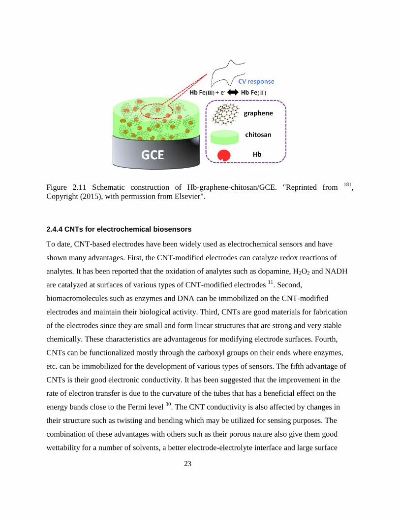
23
Figure 2.11 Schematic construction of Hb-graphene-chitosan/GCE. "Reprinted from 181
,
Copyright (2015), with permission from Elsevier".
2.4.4 CNTs for electrochemical biosensors
To date, CNT-based electrodes have been widely used as electrochemical sensors and have
shown many advantages. First, the CNT-modified electrodes can catalyze redox reactions of
analytes. It has been reported that the oxidation of analytes such as dopamine, H2O2 and NADH
are catalyzed at surfaces of various types of CNT-modified electrodes 11
. Second,
biomacromolecules such as enzymes and DNA can be immobilized on the CNT-modified
electrodes and maintain their biological activity. Third, CNTs are good materials for fabrication
of the electrodes since they are small and form linear structures that are strong and very stable
chemically. These characteristics are advantageous for modifying electrode surfaces. Fourth,
CNTs can be functionalized mostly through the carboxyl groups on their ends where enzymes,
etc. can be immobilized for the development of various types of sensors. The fifth advantage of
CNTs is their good electronic conductivity. It has been suggested that the improvement in the
rate of electron transfer is due to the curvature of the tubes that has a beneficial effect on the
energy bands close to the Fermi level 30
. The CNT conductivity is also affected by changes in
their structure such as twisting and bending which may be utilized for sensing purposes. The
combination of these advantages with others such as their porous nature also give them good
wettability for a number of solvents, a better electrode-electrolyte interface and large surface
24
area. The central hollow cores and outside walls are effective at adsorbing and storing gases such
as oxygen, hydrogen and nitrogen oxide 25
.
As mentioned previously, the active sites in redox proteins and enzymes are typically buried
within a hydrophobic polypeptide chain and the redox centers of proteins or enzymes are
electrically insulated and inaccessible to the electrode surface. This makes it difficult to carry out
direct electrochemistry of proteins and enzyme on conventional electrodes such as gold, platinum
and glassy carbon. However, CNTs can serve as molecular wires that connect the electrode
surface to the active site of enzymes. Consequently, the direct or enhanced electrochemistry of
several proteins and enzymes without the need of mediators has been achieved. A number of
enzyme-based electrochemical biosensors using CNT-modified electrodes based on this approach
have been reported 184185175
.
2.4.5 Self-assembling peptides for electrochemical biosensors
Recently, the potential of using ionic-complementary peptides in biocompatible electrodes to
immobilize glucose oxidase covalently and fabricate glucose biosensors was demonstrated 4849
.
These peptides can self-assemble on surfaces in the form of β-sheet layers that have considerable
biological and physiological stability 5450
and good in vitro and in vivo biocompatibility 55186
.
25
Chapter 31
Dispersion of multi-walled carbon nanotubes in water using ionic-
complementary peptides
Abstract
We demonstrate the non-covalent modification of multi-walled carbon nanotubes (MWNTs)
immersed in aqueous solution using the ionic-complementary peptide EFK16-II. This
modification which presumably arises through the interaction between the hydrophobic side of
the EFK16-II and MWNT sidewalls and orients hydrophilic functional groups toward the
solution phase and enables them to form highly stable dispersions in water. This stability can be
attributed to the electrostatic repulsion between self-assembled peptides on the MWNTs. This
repulsion as determined by zeta potential measurements increases as the pH diverges from the
isoelectric point of ~ 6.7 for EFK16-II. This trend is confirmed by dynamic light scattering
(DLS) measurements of the suspensions showing a decrease in their particle size as the zeta
potential increases. These EFK16-II-MWNT suspensions have been used to modify mica
surfaces. Atomic force microscopy (AFM) and scanning electron microscopy (SEM) images
show that this leads to a uniform distribution of individual modified MWNTs on the mica
surfaces. Transmission electron microscopy (TEM) reveals images of well dispersed fibres with
dimensions similar to that of individual MWNTs. Tissue culture plates previously contacted with
EFK16-II-modified MWNTs have been shown to have enough biocompatibility for growth and
attachment of cells. The biocompatibility and enhanced electrical conductivity that should result
from the modification with these EFK16-II-MWNT suspensions opens up their use in a number
of potential biomedical applications such as the design of bio-electrode interfaces and fabrication
of biosensors with high sensitivity.
1 This chapter is adapted from a paper “Sheikholeslam, M.; Pritzker, M.; Chen, P. Dispersion of multi-walled carbon
nanotubes in water using ionic-complementary peptides. Langmuir, 2012, 28, 12550–12556”.
26
3.1 Introduction
Since the discovery of carbon nanotubes (CNTs) in 19914, considerable interest has been shown
in incorporating them in chemical and biochemical sensors and nano-scale electronic devices and
utilizing them for tissue engineering applications due to their remarkable electronic and
mechanical properties. CNT-modified electrodes have better conductivity than graphite-based
ones and have been shown to exhibit superior performance than those based on single metals
such as Au, Pt and other carbon-based nanomaterials such as C60 and C70 25–29
. Their electronic
properties give CNT electrodes the ability to mediate electron transfer reactions with
electroactive species in solution. To date, CNT-based electrodes have been widely used in
electrochemical sensing. Furthermore, they are capable of providing suitable interfaces for the
signal transfer and neurite outgrowth of neurons as well as supporting the attachment and growth
of osteoblast, fibroblast and cardiac cells 28
.
One of the main methods to prepare a CNT-modified electrode is to coat its surface with a
CNT-containing suspension. However, the first obstacle for electrode modification is that the
strong van der Waals forces between carbon nanotubes leads to their aggregation and poor
dispersion in water and other solvents, which severely limits their usefulness. Although CNT
dispersions can be stabilized in organic solutions such as DMF, ethanol and acetone and then
used to modify electrodes to enhance their electrochemical response, these organic solvents
typically denature biomolecules and so limit their application as biosensors 11
. Thus, the ability to
form stable CNT-containing suspensions in aqueous solutions has attracted considerable
attention. Although covalent stabilization of CNTs (using a method such as acid treatment) can
successfully produce such suspensions, this approach has its problems since it tends to diminish
the excellent optical and electronic character of CNTs and impede their inherent conductivity.
Consequently, the formation of suspensions by non-covalent stabilization of CNTs may be a
more promising method. For this purpose, the modification of CNTs by polymers and surfactants
has been studied 44
. When polymers or non-ionic surfactants are used, a CNT suspension can be
successfully dispersed through steric stabilization by an adsorbed surfactant or polymer layer.
The hydrophobic part of the surfactant makes contact with the CNTs, while its hydrophilic part is
oriented toward the solution. When ionic surfactants adsorb onto CNTs, electrostatic repulsion
27
between their similarly charged ends is the dominant factor, impeding nanotube aggregation and
stabilizing the suspensions 44
.
The use of peptide-based molecules has been explored as an option for dispersion of CNTs.
The association of CNTs with peptides is expected to be useful in biosensor and tissue
engineering applications and in the development of new bioactive nanomaterials. The biological
potential of carbon nanotubes in immunology was investigated by Pantarotto et al. 12
who
demonstrated enhanced in vivo antibody response from covalently linked nanotube-peptide
conjugates. Toward this end, peptide sequences with specific affinities for carbon nanotubes
using phage display have been identified 1314
. These peptides contain sequences rich in histidine
and tryptophan at specific locations. Also, nanotubes have been successfully dispersed in
aqueous solutions by pre-treating with amphiphilic peptide sequences which contain
phenylalanine at specific locations and can fold into α-helixes on nanotube sidewalls 1516
. The
main interaction responsible for suspending carbon nanotubes in water is reported to be π-π
stacking between the aromatic rings in the amino acids and the nanotubes. Arnold et al. 17
investigated an approach utilizing peptide amphiphile (PA) molecules whereby amino acid
sequences are covalently coupled to a hydrophobic alkyl tail. Since the surface of carbon
nanotubes is non-polar and hydrophobic, peptide amphiphiles in an aqueous solution are
expected to self-assemble on this surface and thereby minimize the interfacial energy of the
nanotube-water interface through hydrophobic interaction between the tail and the carbon
nanotubes and as a result exposing the hydrophilic sequence to the water.
Recently, the potential of using ionic-complementary peptides in biocompatible electrodes to
immobilize glucose oxidase and fabricate glucose biosensors was shown 4849
. These peptides can
self-assemble on surfaces in the form of β-sheet layers that have considerable biological and
physiological stability 5450
and good in vitro and in vivo biocompatibility 55186
.
Herein we report a non-covalent method of dispersing MWNTs in aqueous solutions using a
simple self-assembling ionic-complementary peptide EFK16-II that has both a hydrophilic side
(containing lysine and glutamic acid residues) and a hydrophobic side (containing
phenylalanine). The self-assembly of this type of peptide on both hydrophilic (mica) and
28
hydrophobic (HOPG) surfaces has been previously shown 48187
. The hydrophobic side of the
peptide is oriented toward HOPG while the hydrophilic side faces toward the solution. Thus, one
would expect EFK16-II to assemble on the sidewalls of MWNTs through a similar mechanism
when they are sonicated together in an aqueous solution. One of the advantages of this approach
over previously reported ones for CNT modification is that these peptides can self-assemble in
the form of thin -sheet layers, which are about one nanometer thick and hence should not
present a hindrance to CNT conductivity which is important in biosensor and bio-electrode
fabrication. In this way, the orientation of the hydrophilic side of the peptides toward the solution
would enable the MWNTs to be dispersed in an aqueous environment. Furthermore, the
hydrophilic side of the peptide contains eight carboxyl and amino groups, which have been
shown to be capable of immobilizing the GOx enzyme in a glucose biosensor without
denaturation of the enzyme 48
. Consequently, this approach has the potential to improve the
biocompatibility of MWNTs and immobilize a variety of proteins such as enzymes and
antibodies on their sidewalls. Another potentially important benefit of modification of CNTs with
these types of peptides is the enhancement of electrical conductivity suitable for bio-electrode
interfaces. Toward this end, the use of self-assembling peptides to disperse CNTs may be
effective.
3.2 Materials and Methods
3.2.1 Materials
Three peptides were used in this study: i) crude peptide EFK16-II with a sequence of
FEFEFKFKFEFEFKFK, ii) EAK16-II with the same sequence except all Fs were replaced with
As and iii) EK8 with a sequence of EKEKEKEK, where F corresponds to phenylalanine, A to
alanine, E to glutamic acid and K to lysine. All peptides were purchased from CanPeptide Inc.
(Québec, Canada) and used without any further purification. At neutral pH, F and A are neutral
hydrophobic residues, while E and K are negatively and positively charged, respectively. The N
terminus and C-terminus of the peptides were protected by acetyl and amino groups,
respectively, to minimize end-to-end electrostatic interaction between peptides. The peptide
stock solutions were prepared in pure water (18.2 MΩ; Millipore Milli-Q system) at a
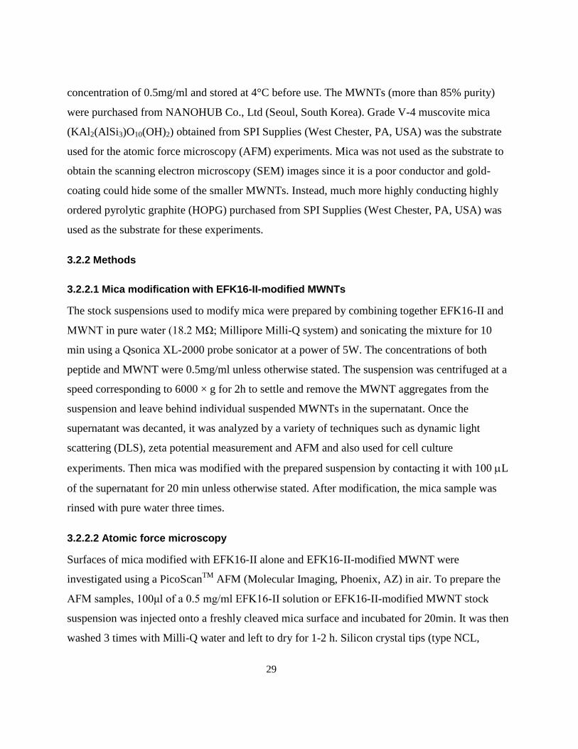
29
concentration of 0.5mg/ml and stored at 4°C before use. The MWNTs (more than 85% purity)
were purchased from NANOHUB Co., Ltd (Seoul, South Korea). Grade V-4 muscovite mica
(KAl2(AlSi3)O10(OH)2) obtained from SPI Supplies (West Chester, PA, USA) was the substrate
used for the atomic force microscopy (AFM) experiments. Mica was not used as the substrate to
obtain the scanning electron microscopy (SEM) images since it is a poor conductor and gold-
coating could hide some of the smaller MWNTs. Instead, much more highly conducting highly
ordered pyrolytic graphite (HOPG) purchased from SPI Supplies (West Chester, PA, USA) was
used as the substrate for these experiments.
3.2.2 Methods
3.2.2.1 Mica modification with EFK16-II-modified MWNTs
The stock suspensions used to modify mica were prepared by combining together EFK16-II and
MWNT in pure water (18.2 MΩ; Millipore Milli-Q system) and sonicating the mixture for 10
min using a Qsonica XL-2000 probe sonicator at a power of 5W. The concentrations of both
peptide and MWNT were 0.5mg/ml unless otherwise stated. The suspension was centrifuged at a
speed corresponding to 6000 × g for 2h to settle and remove the MWNT aggregates from the
suspension and leave behind individual suspended MWNTs in the supernatant. Once the
supernatant was decanted, it was analyzed by a variety of techniques such as dynamic light
scattering (DLS), zeta potential measurement and AFM and also used for cell culture
experiments. Then mica was modified with the prepared suspension by contacting it with 100 L
of the supernatant for 20 min unless otherwise stated. After modification, the mica sample was
rinsed with pure water three times.
3.2.2.2 Atomic force microscopy
Surfaces of mica modified with EFK16-II alone and EFK16-II-modified MWNT were
investigated using a PicoScanTM
AFM (Molecular Imaging, Phoenix, AZ) in air. To prepare the
AFM samples, 100μl of a 0.5 mg/ml EFK16-II solution or EFK16-II-modified MWNT stock
suspension was injected onto a freshly cleaved mica surface and incubated for 20min. It was then
washed 3 times with Milli-Q water and left to dry for 1-2 h. Silicon crystal tips (type NCL,
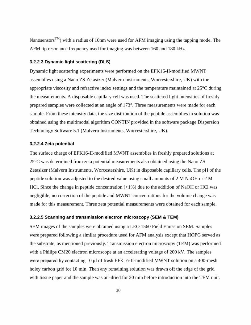
30
NanosensorsTM
) with a radius of 10nm were used for AFM imaging using the tapping mode. The
AFM tip resonance frequency used for imaging was between 160 and 180 kHz.
3.2.2.3 Dynamic light scattering (DLS)
Dynamic light scattering experiments were performed on the EFK16-II-modified MWNT
assemblies using a Nano ZS Zetasizer (Malvern Instruments, Worcestershire, UK) with the
appropriate viscosity and refractive index settings and the temperature maintained at 25°C during
the measurements. A disposable capillary cell was used. The scattered light intensities of freshly
prepared samples were collected at an angle of 173°. Three measurements were made for each
sample. From these intensity data, the size distribution of the peptide assemblies in solution was
obtained using the multimodal algorithm CONTIN provided in the software package Dispersion
Technology Software 5.1 (Malvern Instruments, Worcestershire, UK).
3.2.2.4 Zeta potential
The surface charge of EFK16-II-modified MWNT assemblies in freshly prepared solutions at
25°C was determined from zeta potential measurements also obtained using the Nano ZS
Zetasizer (Malvern Instruments, Worcestershire, UK) in disposable capillary cells. The pH of the
peptide solution was adjusted to the desired value using small amounts of 2 M NaOH or 2 M
HCl. Since the change in peptide concentration (<1%) due to the addition of NaOH or HCl was
negligible, no correction of the peptide and MWNT concentrations for the volume change was
made for this measurement. Three zeta potential measurements were obtained for each sample.
3.2.2.5 Scanning and transmission electron microscopy (SEM & TEM)
SEM images of the samples were obtained using a LEO 1560 Field Emission SEM. Samples
were prepared following a similar procedure used for AFM analysis except that HOPG served as
the substrate, as mentioned previously. Transmission electron microscopy (TEM) was performed
with a Philips CM20 electron microscope at an accelerating voltage of 200 kV. The samples
were prepared by contacting 10 μl of fresh EFK16-II-modified MWNT solution on a 400-mesh
holey carbon grid for 10 min. Then any remaining solution was drawn off the edge of the grid
with tissue paper and the sample was air-dried for 20 min before introduction into the TEM unit.
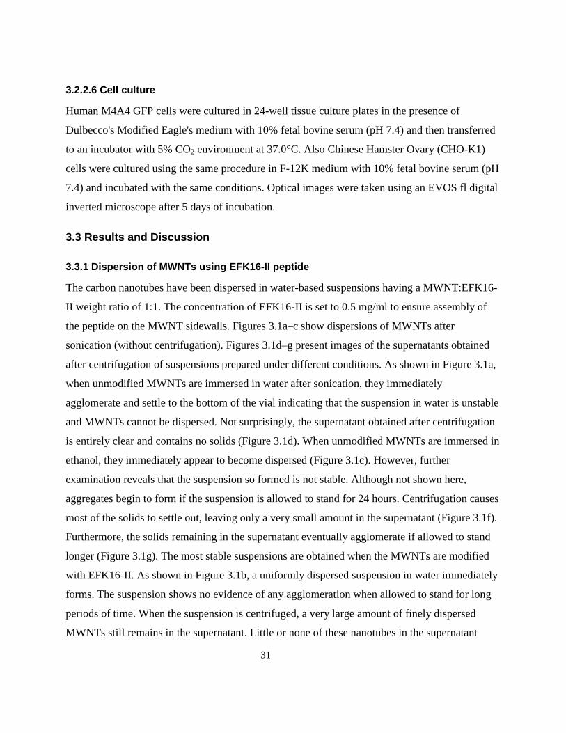
31
3.2.2.6 Cell culture
Human M4A4 GFP cells were cultured in 24-well tissue culture plates in the presence of
Dulbecco's Modified Eagle's medium with 10% fetal bovine serum (pH 7.4) and then transferred
to an incubator with 5% CO2 environment at 37.0°C. Also Chinese Hamster Ovary (CHO-K1)
cells were cultured using the same procedure in F-12K medium with 10% fetal bovine serum (pH
7.4) and incubated with the same conditions. Optical images were taken using an EVOS fl digital
inverted microscope after 5 days of incubation.
3.3 Results and Discussion
3.3.1 Dispersion of MWNTs using EFK16-II peptide
The carbon nanotubes have been dispersed in water-based suspensions having a MWNT:EFK16-
II weight ratio of 1:1. The concentration of EFK16-II is set to 0.5 mg/ml to ensure assembly of
the peptide on the MWNT sidewalls. Figures 3.1a–c show dispersions of MWNTs after
sonication (without centrifugation). Figures 3.1d–g present images of the supernatants obtained
after centrifugation of suspensions prepared under different conditions. As shown in Figure 3.1a,
when unmodified MWNTs are immersed in water after sonication, they immediately
agglomerate and settle to the bottom of the vial indicating that the suspension in water is unstable
and MWNTs cannot be dispersed. Not surprisingly, the supernatant obtained after centrifugation
is entirely clear and contains no solids (Figure 3.1d). When unmodified MWNTs are immersed in
ethanol, they immediately appear to become dispersed (Figure 3.1c). However, further
examination reveals that the suspension so formed is not stable. Although not shown here,
aggregates begin to form if the suspension is allowed to stand for 24 hours. Centrifugation causes
most of the solids to settle out, leaving only a very small amount in the supernatant (Figure 3.1f).
Furthermore, the solids remaining in the supernatant eventually agglomerate if allowed to stand
longer (Figure 3.1g). The most stable suspensions are obtained when the MWNTs are modified
with EFK16-II. As shown in Figure 3.1b, a uniformly dispersed suspension in water immediately
forms. The suspension shows no evidence of any agglomeration when allowed to stand for long
periods of time. When the suspension is centrifuged, a very large amount of finely dispersed
MWNTs still remains in the supernatant. Little or none of these nanotubes in the supernatant
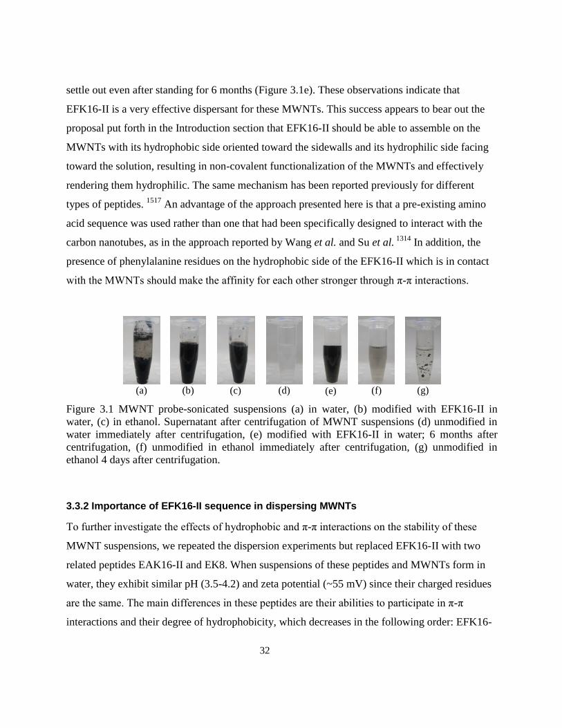
32
settle out even after standing for 6 months (Figure 3.1e). These observations indicate that
EFK16-II is a very effective dispersant for these MWNTs. This success appears to bear out the
proposal put forth in the Introduction section that EFK16-II should be able to assemble on the
MWNTs with its hydrophobic side oriented toward the sidewalls and its hydrophilic side facing
toward the solution, resulting in non-covalent functionalization of the MWNTs and effectively
rendering them hydrophilic. The same mechanism has been reported previously for different
types of peptides. 1517
An advantage of the approach presented here is that a pre-existing amino
acid sequence was used rather than one that had been specifically designed to interact with the
carbon nanotubes, as in the approach reported by Wang et al. and Su et al. 1314
In addition, the
presence of phenylalanine residues on the hydrophobic side of the EFK16-II which is in contact
with the MWNTs should make the affinity for each other stronger through π-π interactions.
(a)
(b)
(c)
(d)
(e)
(f)
(g)
Figure 3.1 MWNT probe-sonicated suspensions (a) in water, (b) modified with EFK16-II in
water, (c) in ethanol. Supernatant after centrifugation of MWNT suspensions (d) unmodified in
water immediately after centrifugation, (e) modified with EFK16-II in water; 6 months after
centrifugation, (f) unmodified in ethanol immediately after centrifugation, (g) unmodified in
ethanol 4 days after centrifugation.
3.3.2 Importance of EFK16-II sequence in dispersing MWNTs
To further investigate the effects of hydrophobic and π-π interactions on the stability of these
MWNT suspensions, we repeated the dispersion experiments but replaced EFK16-II with two
related peptides EAK16-II and EK8. When suspensions of these peptides and MWNTs form in
water, they exhibit similar pH (3.5-4.2) and zeta potential (~55 mV) since their charged residues
are the same. The main differences in these peptides are their abilities to participate in π-π
interactions and their degree of hydrophobicity, which decreases in the following order: EFK16-
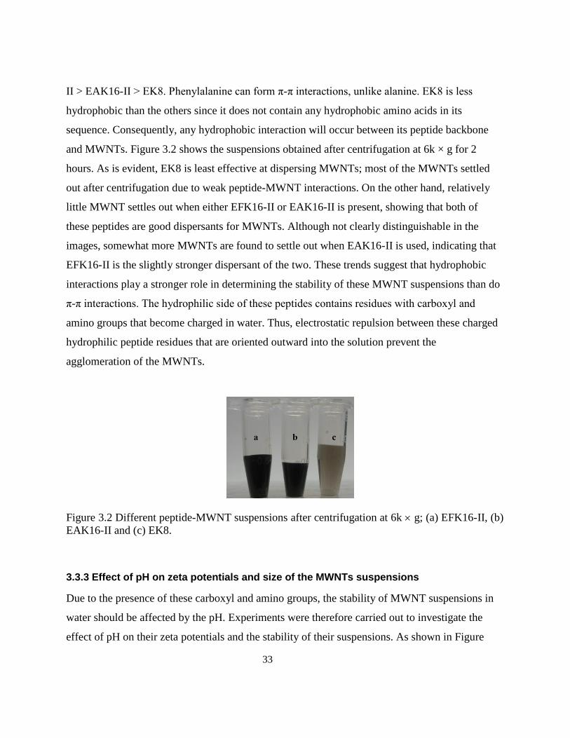
33
II > EAK16-II > EK8. Phenylalanine can form π-π interactions, unlike alanine. EK8 is less
hydrophobic than the others since it does not contain any hydrophobic amino acids in its
sequence. Consequently, any hydrophobic interaction will occur between its peptide backbone
and MWNTs. Figure 3.2 shows the suspensions obtained after centrifugation at 6k × g for 2
hours. As is evident, EK8 is least effective at dispersing MWNTs; most of the MWNTs settled
out after centrifugation due to weak peptide-MWNT interactions. On the other hand, relatively
little MWNT settles out when either EFK16-II or EAK16-II is present, showing that both of
these peptides are good dispersants for MWNTs. Although not clearly distinguishable in the
images, somewhat more MWNTs are found to settle out when EAK16-II is used, indicating that
EFK16-II is the slightly stronger dispersant of the two. These trends suggest that hydrophobic
interactions play a stronger role in determining the stability of these MWNT suspensions than do
π-π interactions. The hydrophilic side of these peptides contains residues with carboxyl and
amino groups that become charged in water. Thus, electrostatic repulsion between these charged
hydrophilic peptide residues that are oriented outward into the solution prevent the
agglomeration of the MWNTs.
Figure 3.2 Different peptide-MWNT suspensions after centrifugation at 6k g; (a) EFK16-II, (b)
EAK16-II and (c) EK8.
3.3.3 Effect of pH on zeta potentials and size of the MWNTs suspensions
Due to the presence of these carboxyl and amino groups, the stability of MWNT suspensions in
water should be affected by the pH. Experiments were therefore carried out to investigate the
effect of pH on their zeta potentials and the stability of their suspensions. As shown in Figure
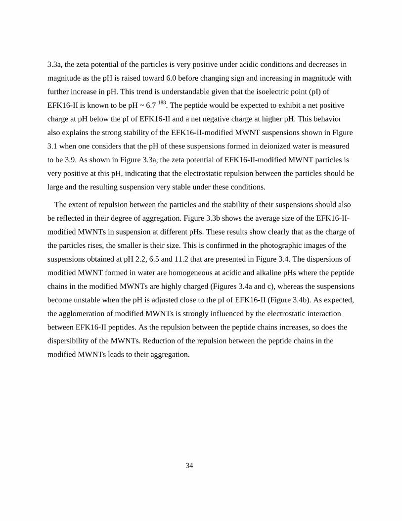
34
3.3a, the zeta potential of the particles is very positive under acidic conditions and decreases in
magnitude as the pH is raised toward 6.0 before changing sign and increasing in magnitude with
further increase in pH. This trend is understandable given that the isoelectric point (pI) of
EFK16-II is known to be pH ~ 6.7 188
. The peptide would be expected to exhibit a net positive
charge at pH below the pI of EFK16-II and a net negative charge at higher pH. This behavior
also explains the strong stability of the EFK16-II-modified MWNT suspensions shown in Figure
3.1 when one considers that the pH of these suspensions formed in deionized water is measured
to be 3.9. As shown in Figure 3.3a, the zeta potential of EFK16-II-modified MWNT particles is
very positive at this pH, indicating that the electrostatic repulsion between the particles should be
large and the resulting suspension very stable under these conditions.
The extent of repulsion between the particles and the stability of their suspensions should also
be reflected in their degree of aggregation. Figure 3.3b shows the average size of the EFK16-II-
modified MWNTs in suspension at different pHs. These results show clearly that as the charge of
the particles rises, the smaller is their size. This is confirmed in the photographic images of the
suspensions obtained at pH 2.2, 6.5 and 11.2 that are presented in Figure 3.4. The dispersions of
modified MWNT formed in water are homogeneous at acidic and alkaline pHs where the peptide
chains in the modified MWNTs are highly charged (Figures 3.4a and c), whereas the suspensions
become unstable when the pH is adjusted close to the pI of EFK16-II (Figure 3.4b). As expected,
the agglomeration of modified MWNTs is strongly influenced by the electrostatic interaction
between EFK16-II peptides. As the repulsion between the peptide chains increases, so does the
dispersibility of the MWNTs. Reduction of the repulsion between the peptide chains in the
modified MWNTs leads to their aggregation.
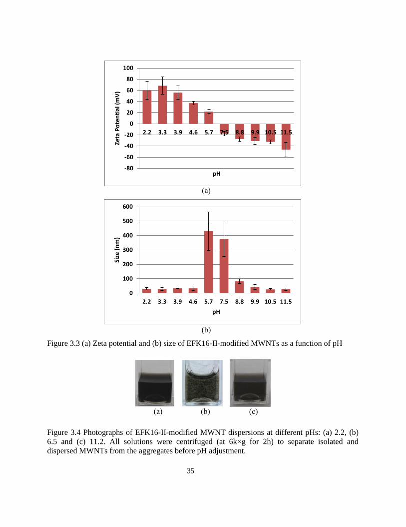
35
(a)
(b)
Figure 3.3 (a) Zeta potential and (b) size of EFK16-II-modified MWNTs as a function of pH
(a)
(b)
(c)
Figure 3.4 Photographs of EFK16-II-modified MWNT dispersions at different pHs: (a) 2.2, (b)
6.5 and (c) 11.2. All solutions were centrifuged (at 6k×g for 2h) to separate isolated and
dispersed MWNTs from the aggregates before pH adjustment.
-80
-60
-40
-20
0
20
40
60
80
100
2.2 3.3 3.9 4.6 5.7 7.5 8.8 9.9 10.5 11.5
Zeta
Po
ten
tial
(m
V)
pH
0
100
200
300
400
500
600
2.2 3.3 3.9 4.6 5.7 7.5 8.8 9.9 10.5 11.5
Size
(n
m)
pH
36
3.3.4 Assessing individual dispersion of MWNTs by AFM, SEM and TEM
Atomic Force Microscopy images show that individual EFK16-II-modified MWNTs are
uniformly distributed over a mica surface (Figure 3.5a). These images have been analyzed using
a procedure for tip deconvolution explained elsewhere 53
to estimate the diameters of the
MWNTs. The height profile along the green line shown in Figure 3.5a has been obtained to gain
an estimate of the dimensions of a MWNT lying on the surface. As shown below the AFM
image, this analysis reveals that the MWNT has a diameter between 5 to 15 nm as it lies along
the surface which agrees with the information concerning the dimensions of the nanotubes
provided by the vendor. This confirms that the nanotubes remain in a non-aggregated state when
modified with EFK16-II. For the purposes of comparison, Figure 3.5b shows an image of a mica
surface that had been modified by a sonicated solution containing EFK16-II but no MWNTs. In
this solution, many more self-assembled peptides (an example of one such assembly is indicated
by the arrow) appear on the surface of mica than that shown in Figure 3.5a when MWNTs are
present. Although EFK16-II often forms fibrils on the surface 48
, it appears that the different
conditions of our experiments, such as the use of probe sonication to dissolve the peptide in
water, favors the formation of globular assemblies rather than fibrils. Similar behavior has been
reported for the peptide EAK16-IV at a different pH 189
. The difference in the number of peptide
assemblies that appear depending on whether or not MWNTs are present (Figures 3.5a and b)
can likely be attributed to the uptake of EFK16-II by the MWNTs which should leave many
fewer free peptide molecules available to self-assemble on the surface.
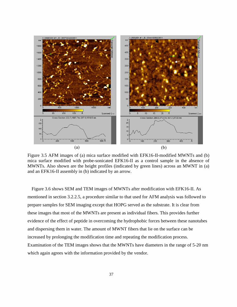
37
(a)
(b)
Figure 3.5 AFM images of (a) mica surface modified with EFK16-II-modified MWNTs and (b)
mica surface modified with probe-sonicated EFK16-II as a control sample in the absence of
MWNTs. Also shown are the height profiles (indicated by green lines) across an MWNT in (a)
and an EFK16-II assembly in (b) indicated by an arrow.
Figure 3.6 shows SEM and TEM images of MWNTs after modification with EFK16-II. As
mentioned in section 3.2.2.5, a procedure similar to that used for AFM analysis was followed to
prepare samples for SEM imaging except that HOPG served as the substrate. It is clear from
these images that most of the MWNTs are present as individual fibers. This provides further
evidence of the effect of peptide in overcoming the hydrophobic forces between these nanotubes
and dispersing them in water. The amount of MWNT fibers that lie on the surface can be
increased by prolonging the modification time and repeating the modification process.
Examination of the TEM images shows that the MWNTs have diameters in the range of 5-20 nm
which again agrees with the information provided by the vendor.
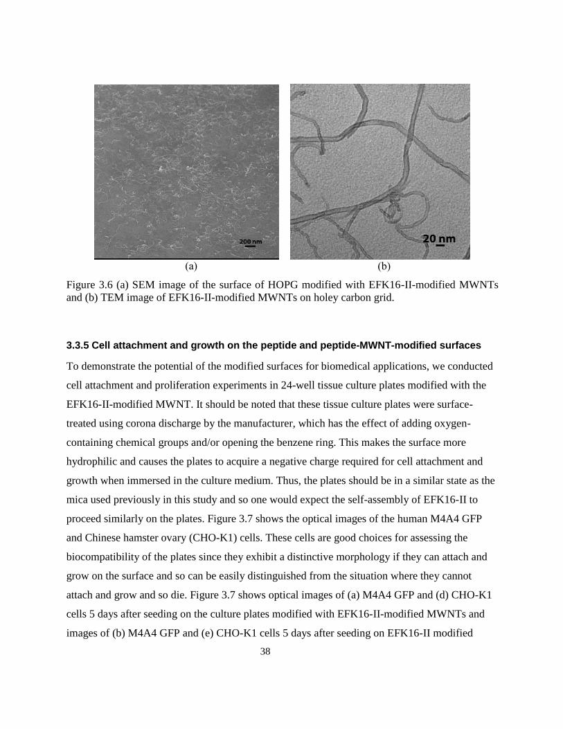
38
(a)
(b)
Figure 3.6 (a) SEM image of the surface of HOPG modified with EFK16-II-modified MWNTs
and (b) TEM image of EFK16-II-modified MWNTs on holey carbon grid.
3.3.5 Cell attachment and growth on the peptide and peptide-MWNT-modified surfaces
To demonstrate the potential of the modified surfaces for biomedical applications, we conducted
cell attachment and proliferation experiments in 24-well tissue culture plates modified with the
EFK16-II-modified MWNT. It should be noted that these tissue culture plates were surface-
treated using corona discharge by the manufacturer, which has the effect of adding oxygen-
containing chemical groups and/or opening the benzene ring. This makes the surface more
hydrophilic and causes the plates to acquire a negative charge required for cell attachment and
growth when immersed in the culture medium. Thus, the plates should be in a similar state as the
mica used previously in this study and so one would expect the self-assembly of EFK16-II to
proceed similarly on the plates. Figure 3.7 shows the optical images of the human M4A4 GFP
and Chinese hamster ovary (CHO-K1) cells. These cells are good choices for assessing the
biocompatibility of the plates since they exhibit a distinctive morphology if they can attach and
grow on the surface and so can be easily distinguished from the situation where they cannot
attach and grow and so die. Figure 3.7 shows optical images of (a) M4A4 GFP and (d) CHO-K1
cells 5 days after seeding on the culture plates modified with EFK16-II-modified MWNTs and
images of (b) M4A4 GFP and (e) CHO-K1 cells 5 days after seeding on EFK16-II modified
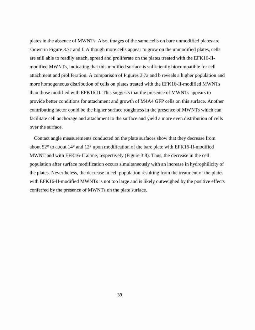
39
plates in the absence of MWNTs. Also, images of the same cells on bare unmodified plates are
shown in Figure 3.7c and f. Although more cells appear to grow on the unmodified plates, cells
are still able to readily attach, spread and proliferate on the plates treated with the EFK16-II-
modified MWNTs, indicating that this modified surface is sufficiently biocompatible for cell
attachment and proliferation. A comparison of Figures 3.7a and b reveals a higher population and
more homogeneous distribution of cells on plates treated with the EFK16-II-modified MWNTs
than those modified with EFK16-II. This suggests that the presence of MWNTs appears to
provide better conditions for attachment and growth of M4A4 GFP cells on this surface. Another
contributing factor could be the higher surface roughness in the presence of MWNTs which can
facilitate cell anchorage and attachment to the surface and yield a more even distribution of cells
over the surface.
Contact angle measurements conducted on the plate surfaces show that they decrease from
about 52° to about 14° and 12° upon modification of the bare plate with EFK16-II-modified
MWNT and with EFK16-II alone, respectively (Figure 3.8). Thus, the decrease in the cell
population after surface modification occurs simultaneously with an increase in hydrophilicity of
the plates. Nevertheless, the decrease in cell population resulting from the treatment of the plates
with EFK16-II-modified MWNTs is not too large and is likely outweighed by the positive effects
conferred by the presence of MWNTs on the plate surface.
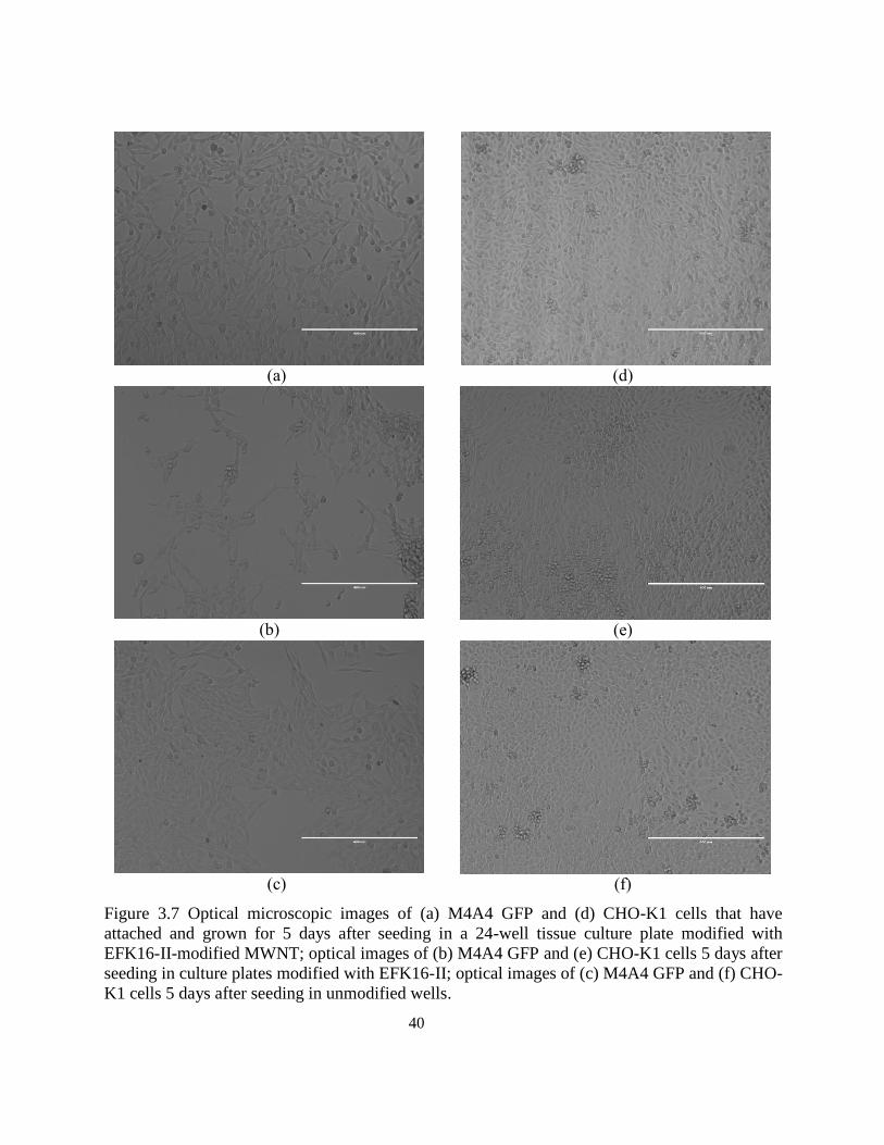
40
(a)
(d)
(b)
(e)
(c)
(f)
Figure 3.7 Optical microscopic images of (a) M4A4 GFP and (d) CHO-K1 cells that have
attached and grown for 5 days after seeding in a 24-well tissue culture plate modified with
EFK16-II-modified MWNT; optical images of (b) M4A4 GFP and (e) CHO-K1 cells 5 days after
seeding in culture plates modified with EFK16-II; optical images of (c) M4A4 GFP and (f) CHO-
K1 cells 5 days after seeding in unmodified wells.
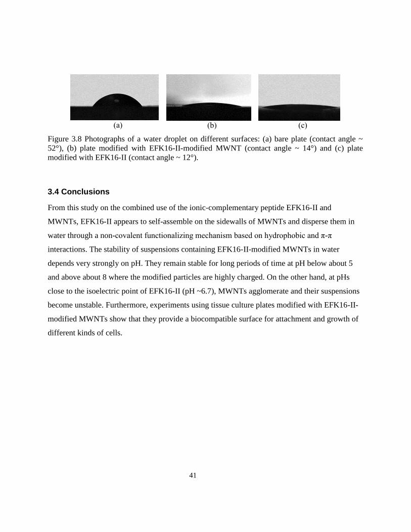
41
(a)
(b)
(c)
Figure 3.8 Photographs of a water droplet on different surfaces: (a) bare plate (contact angle ~
52°), (b) plate modified with EFK16-II-modified MWNT (contact angle ~ 14°) and (c) plate
modified with EFK16-II (contact angle ~ 12°).
3.4 Conclusions
From this study on the combined use of the ionic-complementary peptide EFK16-II and
MWNTs, EFK16-II appears to self-assemble on the sidewalls of MWNTs and disperse them in
water through a non-covalent functionalizing mechanism based on hydrophobic and π-π
interactions. The stability of suspensions containing EFK16-II-modified MWNTs in water
depends very strongly on pH. They remain stable for long periods of time at pH below about 5
and above about 8 where the modified particles are highly charged. On the other hand, at pHs
close to the isoelectric point of EFK16-II (pH ~6.7), MWNTs agglomerate and their suspensions
become unstable. Furthermore, experiments using tissue culture plates modified with EFK16-II-
modified MWNTs show that they provide a biocompatible surface for attachment and growth of
different kinds of cells.
42
Chapter 42
Hybrid Peptide-Carbon Nanotube
Dispersions and Hydrogels
Abstract
Scanning probe microscopy (SPM) techniques based on nano-mechanical measurements
(topography, adhesion, modulus) and electric force microscopy (EFM) have been used to
examine mica surfaces modified with the ionic-complementary peptide EFK8 alone and with
EFK8–single-walled carbon nanotube (SWNT) dispersions in water in order to gain a deeper
understanding of the interaction between nanotubes and ionic-complementary peptides. Through
the use of these techniques, it has been shown for the first time that peptide fibers can be
distinguished from SWNTs and peptide-wrapped SWNTs. SPM images reveal features
consistent with two types of helical structures: EFK8 fibers wrapped around each other during
self-assembly and EFK8 fibers wrapped around SWNTs. In this second structure, EFK8 chains
should be oriented with their hydrophobic sides oriented toward the SWNTs and their
hydrophilic sides toward the water, thereby enabling the dispersion of the nanotubes in aqueous
media. We have also demonstrated the formation of hybrid EFK8-SWNT hydrogels that have
potentially superior physical and mechanical properties over those of other hydrogels and opens
up new applications for this type of material. To the best of our knowledge, this is the first work
reporting the formation of a composite hydrogel made of an ionic-complementary peptide and
carbon nanotubes.
2 This chapter is adapted from a paper “Sheikholeslam, M.; Pritzker, M.; Chen, P. Hybrid peptide–carbon nanotube
dispersions and hydrogels. Carbon, 2014, 71, 284–293”.
43
4.1 Introduction
In the past two decades, ionic-complementary peptides have been used for a wide range of
applications ranging from anti-cancer drug delivery to biocompatible hydrogels as scaffolds for
3D cell cultures and tissue engineering 22,47–52
. Before the introduction of these peptides, 3D cell
cultures required the use of either synthetic scaffolds (such as PLLA and PGA biopolymers,
calcium phosphate mesh and PEG gels) that unfortunately did not have the same fiber and pore
size and chemical features of the natural extracellular matrix (ECM) or animal-derived materials
(including bovine collagen and gelatin, fibronectin and Matrigel). The inclusion of these
materials could contaminate the cell culture with undefined material and cause problems related
to cell signaling, protein content and reproducibility 190
. It has been shown that the use of ionic-
complementary peptides can provide a better scaffold for cells alleviating the above mentioned
problems 190
.
Since their discovery in 1991 4, carbon nanotubes (CNTs) have attracted the attention of many
researchers in different fields of engineering and science and emerged as one of the leading
multifunctional materials in the field of nano-engineering. They have shown great promise for
applications in biomedical engineering by enhancing the properties of biomaterials such as
composite materials for tissue engineering 27,28,31–35
and in the fabrication of biomedical devices
such as biosensors 25,26
.
Hydrogels are interesting materials for use in tissue engineering due to their structural
similarity with actual tissues in the body and their biocompatibility. Consequently, they are being
used as scaffolds to fabricate new tissues. Due to their remarkable electronic and mechanical
properties carbon nanotubes (CNTs) have been incorporated into hydrogels to modify their
physical and mechanical properties for a variety of tissue applications 137–144
. In the past few
years, the incorporation of CNTs in collagen hydrogels has been shown to increase the electrical
conductivity of the hydrogels and to enable better control of their mechanical properties 145–152
.
Conductive hydrogels are useful for mimicking and regenerating tissues in which electrical
signals are propagated such as in cardiac muscles and neural tissue 139,141–143,148,149,151–153
. At the
same time, it has been shown that the mechanical properties of the scaffold play a major role in
the behavior and fate of cells, particularly stem cells 120,122,125,154
. This opens up the possibility of
44
using soft hydrogels for a wider range of tissues by using CNT-based scaffolds to improve their
mechanical properties.
The first problem in using CNTs in biomedical applications is to overcome the van der Waals
forces between CNT fibers so that they can be dispersed particularly in aqueous media and/or
chemically functionalized. We have previously demonstrated this can be achieved through the
addition of the ionic-complementary peptide EFK16-II that non-covalently stabilizes multi-
walled carbon nanotubes (MWNTs) in aqueous solution via hydrophobic and π-stacking
interactions 191
. In the current chapter, we report on the dispersion of single-walled carbon
nanotubes (SWNTs) in aqueous media with another ionic-complementary peptide EFK8
(FEFEFKFK) containing the same amino acids but with half the number of residues in an
EFK16-II sequence. Being an ionic complementary peptide with the same amino acid groups,
EFK8 should interact with carbon nanotubes as EFK16-II does through hydrophobic bonding and
π-stacking.
Although our previous study showed evidence of a strong interaction between EFK16-II and
the MWNTs, it did not yield information concerning the particular structure formed by the
peptide and nanotube in aqueous solutions. In the current study, we turn our attention to the
interaction between EFK8 and SWNTs and use several high-resolution surface probe microscopy
(SPM) techniques to reveal some details of the structure they form. Finally, we investigate a
potential application of this EFK8-SWNT interaction by demonstrating whether it is possible to
form a hybrid hydrogel involving the peptide and nanotube in aqueous media. To the best of our
knowledge, the formation of a composite hydrogel made of an ionic-complementary peptide and
carbon nanotubes has not been previously reported.
4.2 Materials and Methods
4.2.1 Materials
The ionic complementary peptide EFK8 with a sequence of FEFEFKFK where F corresponds to
phenylalanine, E to glutamic acid and K to lysine was used in this study. This peptide was
synthesized in our laboratory using an Aapptec Apex 396 peptide synthesizer. At neutral pH, F is
a neutral hydrophobic residue, while E and K are negatively and positively charged, respectively.
45
The peptide was protected by acetyl and amino groups at the N terminus and C-terminus,
respectively, to prevent end-to-end electrostatic interactions between peptides. EFK8 was
dissolved in pure water (18.2 MΩ; Millipore Milli-Q system) at a concentration of 0.5mg/ml to
prepare the peptide stock solution and then stored at 4°C before use. The metallic SWNTs
(carbon > 90%, carbon as SWNT > 77%) were purchased from Sigma-Aldrich Co (catalog#
727777, lot# MKBH7136V). The substrate used for atomic force microscopy (AFM) was Grade
V-4 muscovite mica purchased from SPI Supplies (West Chester, PA, USA).
4.2.2 Methods
4.2.2.1 Peptide synthesis
All amino acids (Fmoc protected), activator 2-(6-chloro-1H-benzotriazole-1-yl)-1,1,3,3-
tetramethylaminium hexafluorophosphate (HCTU) and Rink Amide-AM resin were obtained
from Aapptec LLC (USA). All other solutions were purchased from Acros Organics (USA). The
EFK8 peptide with a molecular weight of 1162.60 g/mol was synthesized in our laboratory using
the solid-phase peptide synthesis (SPPS) method using an Aapptec Apex 396 peptide synthesizer
(Aapptec LLC, USA) before being purified by repeated precipitation in cold ether. Then it was
freeze-dried and the final powder stored in a refrigerator. Matrix-assisted laser desorption
ionization time of flight mass spectroscopy (Q-TOF Ultima Global, Waters, Milford, MA, USA)
was used to measure the molar mass of the synthesized peptide.
4.2.2.2 SWNT dispersion preparation
The stock suspensions were prepared by combining EFK8 and as-received SWNT (carbon >
90%, carbon as SWNT > 77%) together at a 1:1 mass ratio in pure water (18.2 MΩ; Millipore
Milli-Q system) to yield concentrations of 0.5mg/ml for both the peptide and SWNTs. The
concentration of 0.5mg/ml for the SWNTs is based on the mass of as-received material and so
may include components that are not actual SWNT. The suspensions were then mixed for 1 hour
using a Qsonica XL-2000 probe sonicator at a power of 1W and centrifuged at a speed of 30,000
× g for 30 min to produce a supernatant that was decanted for later use in AFM experiments and
hydrogel formation. The centrifugation speed falls in the recommended range by the SWNT
supplier (Sigma-Aldrich) to remove impurities and produce good dispersions for AFM imaging.
46
4.2.2.3 Atomic and electric force microscopy
A Dimension Icon
AFM (Bruker Nano Surfaces, Santa Barbara, CA) was used in air to conduct
examination of mica surfaces modified with EFK8 and EFK8-SWNTs. The samples investigated
by AFM were prepared by incubating 50μl of 0.5 mg/ml EFK8-modified SWNT stock
suspensions on a freshly cleaved mica surface for 30 sec. The surface was then washed 3 times
with Milli-Q water and left to dry for 1-2 h. Silicon nitride tips (type SCANASYST-AIR,
Bruker) with a radius of 2 nm were used for AFM imaging in the PeakForce
QNM mode. In
this mode, a force-distance measurement is conducted at every single point of the image and
nano-mechanical properties are extracted from the collected data. The user selects the maximum
interaction between the probe and surface during a scan termed the peak force set-point. As the
tip moves from point to point along a scan, it is automatically moved to a distance from the
surface corresponding to the peak force set-point. The probe is then retracted from the surface
and the interaction force continually monitored. This force decreases as the tip-sample distance
increases, passing through a point where it becomes zero (due to a balance between repulsive and
attractive forces between the tip and the sample) and then to a point where it becomes a
minimum. At this point, the tip detaches from the sample. This minimum force gives a measure
of the adhesion of the tip to the sample. The sample modulus which is a measure of sample
stiffness can also be determined by fitting the Derjaguin-Muller-Toporov model to the force-
distance relationship that is measured during the retraction of the tip 192
. The fitting and
parameter estimation are carried out by software for every force-distance curve.
Electric force microscopy (EFM) using the Icon AFM was conducted in air on samples
prepared on mica surfaces. This technique enables electric properties on a sample surface to be
mapped by measuring the electrostatic force between the surface and a biased oscillating AFM
cantilever. The EFM signal is generated from the shift in the phase lag between the drive signal
and cantilever response resulting from the effect of the electrical field on the resonant frequency
of the oscillating cantilever above the surface. The Icon AFM unit employed in this study was
operated using the LiftModeTM
in which the tip scanned every line twice; the first scan measured
the topography using the tapping mode, while the second one detected the electric field at a
designated height above the surface. The second scan was conducted with the tip held at a lift
47
height of 25 nm and a bias voltage of 2 V relative to the sample. The tips used in this technique
consisted of silicon coated with platinum-iridium (type SCM-PIT, Bruker) and had a radius of 20
nm and resonance frequency close to 75 kHz.
4.2.2.4 Transmission and scanning electron microscopy
Transmission electron microscopy (TEM) was performed with a Philips CM20 electron
microscope at an accelerating voltage of 100 kV. The samples were prepared by contacting 10 μl
of fresh EFK8-modified MWNT solution on a 400-mesh holey carbon grid for 2 min. Then any
remaining solution was drawn off the edge of the grid with tissue paper and the sample was air-
dried for 20 min before introduction into the TEM unit. Hydrogel samples required special
preparation so that they could be examined by SEM. The first step involved dehydration in stages
by successive immersion in 30%, 50%, 70%, 90% and 100% ethanol solutions over 2 days. Once
dehydrated, the hydrogels were dried using the critical point method employing supercritical
CO2. Once dried, the scaffolds were sputtered with gold for 100 sec prior to imaging with SEM.
The SEM images of all samples were obtained using a Zeiss Ultra Plus SEM.
4.2.2.5 Hydrogel formation
EFK8 and EFK8-SWNT solutions were added to inserts with membranes at their bottoms
suspended in a 24-well cell culture plate (BD Biosciences, San Jose, CA). Hydrogel formation
was promoted by the monovalent salts present in the cell culture medium (F-12K with 10% fetal
bovine serum) injected into the space between each insert and well wall so that they could reach
the well bottom. The salt then diffused from the media across the membrane into the peptide or
peptide-CNT dispersion to trigger hydrogel formation. The solutions were left for 2 hour at room
temperature to ensure hydrogel formation was complete.
4.3 Results and Discussion
4.3.1 EFK8-SWNT hybrid dispersion and their interaction
A SWNT:EFK8 weight ratio of 1:1 was used to disperse the SWNTs in water. To ensure self-
assembly of EFK8, a peptide concentration of 0.5mg/ml was chosen. Figure 4.1a shows the
prepared dispersion after 30 min centrifugation at the speed of 30000 × g. These results clearly
48
indicate that the SWNTs have been dispersed through the addition of the peptide, confirming that
they have been rendered hydrophilic through their interaction with the EFK8, similar to that
observed previously when EFK16 was used 191
. Being an ionic-complementary peptide, EFK8
has both a hydrophilic (including E and K) and a hydrophobic side (including F). Presumably,
the peptide has oriented itself with its hydrophobic side pointing toward the SWNT and its
hydrophilic side toward the external solution. A TEM image of a portion of the dispersion that
has been dried (Figure 4.1b) shows evidence of a number of SWNTs that are individually
dispersed as a result of the interaction with EFK8 although the peptide is too small to be visible.
To examine the interaction at higher resolution, we also obtained AFM images of the EFK8-
SWNT sample. A representative example is presented in Figure 4.1c. The highlighted region
shows evidence consistent with one strand wrapping around another fiber to form a structure
consistent with a helical pattern along its length. This can be seen more clearly in the image of
the highlighted region in Figure 4.1c shown at higher magnification (Figure 4.1d) and in the 3-D
image of the highlighted region in Figure 4.1d shown at still higher magnification. In addition,
many small fibers that are distributed over the surface appear to be unassociated with other
fibers. Presumably, these are self-assembled EFK8 fibers. The presence of these EFK8 fibers on
the surface shows that not all of the peptides interact with the SWNTs and are consumed to
disperse them. Instead, a significant portion self-assembles to form EFK8-only fibers
independently of the presence of the nanotubes. This is an important observation since these free
peptides would still be available to participate in other processes under the appropriate
conditions. One example is hydrogel formation if higher concentrations of the peptide are added.
The inset in the bottom left corner of Figure 4.1c shows an AFM topography image of a sample
obtained in the presence of EFK8-only with no SWNT present. A structure consistent with the
helical pattern appearing in the EFK8-SWNT images is evident along many of the fibers in this
inset, suggesting that EFK8 is capable of forming helices during self-assembly. This is also
consistent with a previously reported study showing that a similar peptide KFE8 forms helices
during self-assembly in the absence of carbon nanotubes 193
, which is discussed in more detail
later in this chapter.
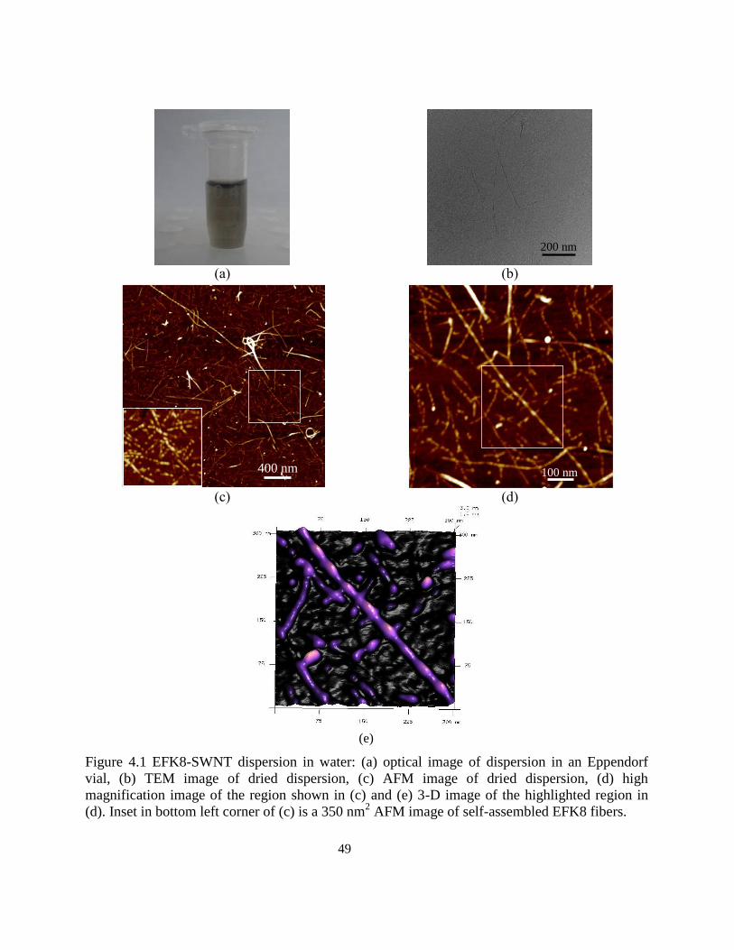
49
(a)
(b)
(c)
(d)
(e)
Figure 4.1 EFK8-SWNT dispersion in water: (a) optical image of dispersion in an Eppendorf
vial, (b) TEM image of dried dispersion, (c) AFM image of dried dispersion, (d) high
magnification image of the region shown in (c) and (e) 3-D image of the highlighted region in
(d). Inset in bottom left corner of (c) is a 350 nm2 AFM image of self-assembled EFK8 fibers.
200 nm
100 nm 400 nm
50
4.3.2 Nano-mechanical study of EFK8-SWNT hybrid dispersion
However, the main difficulty in interpreting the topography image shown in Figure 4.1c is that it
is not possible to unambiguously conclude that the long wrapped fiber is in fact an EFK8-
wrapped SWNT. Another possible interpretation is that a couple (or more) peptide have bundled
together and formed this long fiber, as has been previously reported by Marini et al. 193
. To
examine this question further, we obtained AFM images of the EFK8-SWNT samples in the PF-
QNM mode and analyzed the data collected from the topography, adhesion and modulus
channels. This new technique has been recently used to map the mechanical properties of some
polymers and proteins 194–198
. However, to the best of our knowledge, this is the first time that it
has been applied to investigate the interaction between peptides and CNTs. Our main intention
here is to use this technique to identify and distinguish between the various fibers rather than to
determine their properties per se. This can open up a powerful new tool to characterize hybrid
nanostructures. In the PF-QNM mode, the AFM conducts a force-distance measurement at every
single pixel of the image. Different types of data such as topography, adhesion, modulus,
dissipation, etc. are then quantitatively extracted from these measured force-distance curves. In
the current analysis, we have combined topography, adhesion and modulus data to better
distinguish between peptide-wrapped SWNTs and peptide bundle fibers.
To make sure that enough long peptide fibers and EFK8-wrapped SWNTs exist and a better
comparison of their adhesion and modulus measurements can be made, we incubated both
peptide and peptide-SWNT dispersions for five days. Figures 4.2a-c show the images of a sample
containing EFK8 only. The same portion of the sample is viewed in these images, but processed
using the topography (Figure 4.2a), adhesion (Figure 4.2b) and modulus (Figure 4.2c) data
collected during the same scan using the PF-QNM mode. Due to the large incubation time,
peptide fibers have bundled together and grown thicker and longer. The adhesion and modulus
channels both show a homogeneous distribution of fiber adhesion and modulus over the surface
(Figures 4.2b and c). The topography, adhesion and modulus images of a sample obtained when
EFK8 and SWNT are combined together are presented in Figures 4.2d, e and f, respectively. The
topography image (Figure 4.2d) appears to be similar to that obtained in the EFK8-only sample
with many fibers entangled together and largely indistinguishable from each other. However,
51
some fibers in the adhesion image appear brighter than others (Figure 4.2e). In such an image,
the brighter an object appears, the greater is its adhesion to the AFM probe. Based on the nature
of the peptides and carbon nanotubes, we would expect a softer object such as EFK8 to exhibit
stronger adhesion than a harder one such as SWNT. Consequently, darker fibers (shown by
dotted blue arrow) in the adhesion image may correspond to SWNTs and lighter ones (red arrow)
to the peptide. In a modulus image, fibers that appear bright have higher modulus than darker
ones. The image shown in Figure 4.2f obtained using this channel confirms the conclusion
reached based on the topography and adhesion data. The same fibers indicated by the dotted blue
arrows have both lower adhesion (Figure 4.2e) and higher modulus (Figure 4.2f) which is
consistent with that expected if they consist of SWNTs. Thus, by combining information
gathered from these three data channels, peptide fibers and SWNTs can be distinguished from
each other.
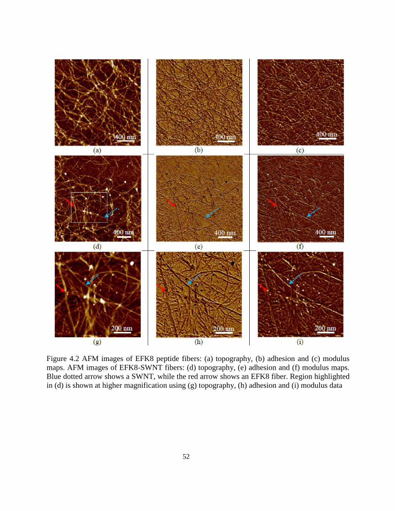
52
Figure 4.2 AFM images of EFK8 peptide fibers: (a) topography, (b) adhesion and (c) modulus
maps. AFM images of EFK8-SWNT fibers: (d) topography, (e) adhesion and (f) modulus maps.
Blue dotted arrow shows a SWNT, while the red arrow shows an EFK8 fiber. Region highlighted
in (d) is shown at higher magnification using (g) topography, (h) adhesion and (i) modulus data
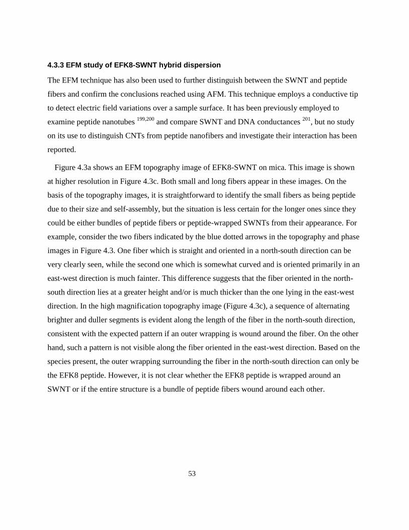
53
4.3.3 EFM study of EFK8-SWNT hybrid dispersion
The EFM technique has also been used to further distinguish between the SWNT and peptide
fibers and confirm the conclusions reached using AFM. This technique employs a conductive tip
to detect electric field variations over a sample surface. It has been previously employed to
examine peptide nanotubes 199,200
and compare SWNT and DNA conductances 201
, but no study
on its use to distinguish CNTs from peptide nanofibers and investigate their interaction has been
reported.
Figure 4.3a shows an EFM topography image of EFK8-SWNT on mica. This image is shown
at higher resolution in Figure 4.3c. Both small and long fibers appear in these images. On the
basis of the topography images, it is straightforward to identify the small fibers as being peptide
due to their size and self-assembly, but the situation is less certain for the longer ones since they
could be either bundles of peptide fibers or peptide-wrapped SWNTs from their appearance. For
example, consider the two fibers indicated by the blue dotted arrows in the topography and phase
images in Figure 4.3. One fiber which is straight and oriented in a north-south direction can be
very clearly seen, while the second one which is somewhat curved and is oriented primarily in an
east-west direction is much fainter. This difference suggests that the fiber oriented in the north-
south direction lies at a greater height and/or is much thicker than the one lying in the east-west
direction. In the high magnification topography image (Figure 4.3c), a sequence of alternating
brighter and duller segments is evident along the length of the fiber in the north-south direction,
consistent with the expected pattern if an outer wrapping is wound around the fiber. On the other
hand, such a pattern is not visible along the fiber oriented in the east-west direction. Based on the
species present, the outer wrapping surrounding the fiber in the north-south direction can only be
the EFK8 peptide. However, it is not clear whether the EFK8 peptide is wrapped around an
SWNT or if the entire structure is a bundle of peptide fibers wound around each other.
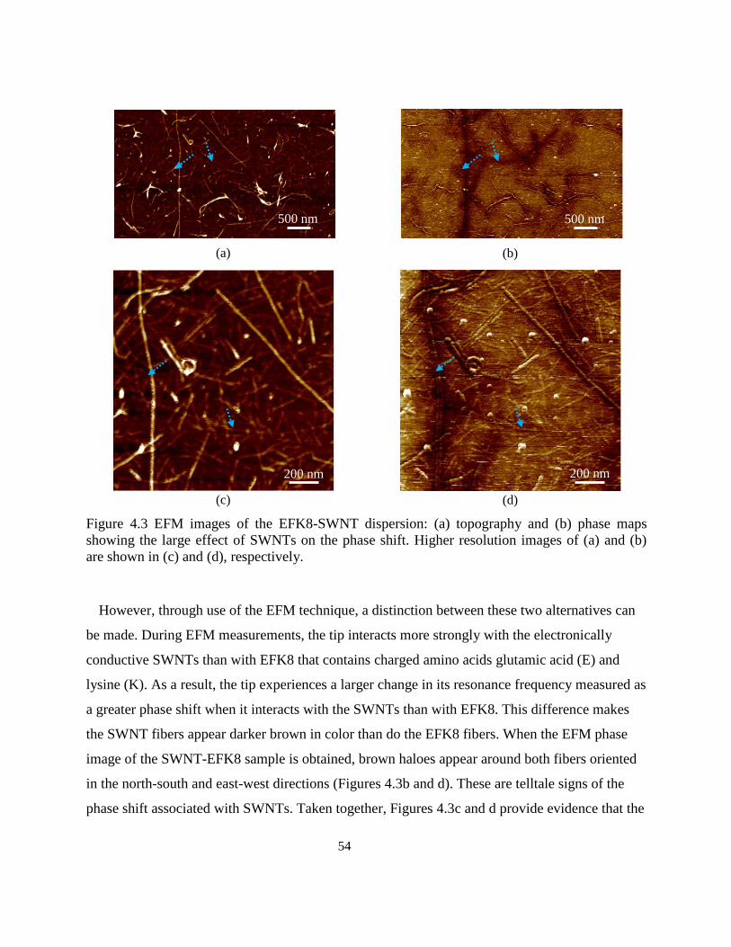
54
(a)
(b)
(c)
(d)
Figure 4.3 EFM images of the EFK8-SWNT dispersion: (a) topography and (b) phase maps
showing the large effect of SWNTs on the phase shift. Higher resolution images of (a) and (b)
are shown in (c) and (d), respectively.
However, through use of the EFM technique, a distinction between these two alternatives can
be made. During EFM measurements, the tip interacts more strongly with the electronically
conductive SWNTs than with EFK8 that contains charged amino acids glutamic acid (E) and
lysine (K). As a result, the tip experiences a larger change in its resonance frequency measured as
a greater phase shift when it interacts with the SWNTs than with EFK8. This difference makes
the SWNT fibers appear darker brown in color than do the EFK8 fibers. When the EFM phase
image of the SWNT-EFK8 sample is obtained, brown haloes appear around both fibers oriented
in the north-south and east-west directions (Figures 4.3b and d). These are telltale signs of the
phase shift associated with SWNTs. Taken together, Figures 4.3c and d provide evidence that the
500 nm 500 nm
200 nm 200 nm
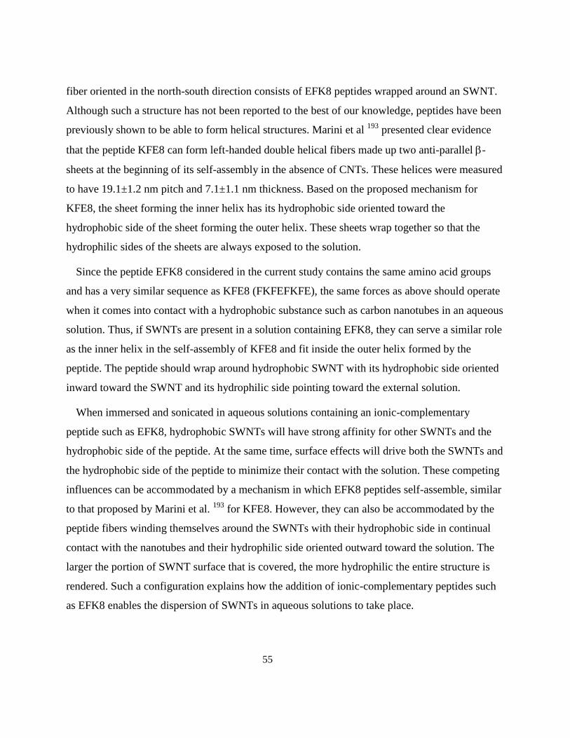
55
fiber oriented in the north-south direction consists of EFK8 peptides wrapped around an SWNT.
Although such a structure has not been reported to the best of our knowledge, peptides have been
previously shown to be able to form helical structures. Marini et al 193
presented clear evidence
that the peptide KFE8 can form left-handed double helical fibers made up two anti-parallel -
sheets at the beginning of its self-assembly in the absence of CNTs. These helices were measured
to have 19.1±1.2 nm pitch and 7.1±1.1 nm thickness. Based on the proposed mechanism for
KFE8, the sheet forming the inner helix has its hydrophobic side oriented toward the
hydrophobic side of the sheet forming the outer helix. These sheets wrap together so that the
hydrophilic sides of the sheets are always exposed to the solution.
Since the peptide EFK8 considered in the current study contains the same amino acid groups
and has a very similar sequence as KFE8 (FKFEFKFE), the same forces as above should operate
when it comes into contact with a hydrophobic substance such as carbon nanotubes in an aqueous
solution. Thus, if SWNTs are present in a solution containing EFK8, they can serve a similar role
as the inner helix in the self-assembly of KFE8 and fit inside the outer helix formed by the
peptide. The peptide should wrap around hydrophobic SWNT with its hydrophobic side oriented
inward toward the SWNT and its hydrophilic side pointing toward the external solution.
When immersed and sonicated in aqueous solutions containing an ionic-complementary
peptide such as EFK8, hydrophobic SWNTs will have strong affinity for other SWNTs and the
hydrophobic side of the peptide. At the same time, surface effects will drive both the SWNTs and
the hydrophobic side of the peptide to minimize their contact with the solution. These competing
influences can be accommodated by a mechanism in which EFK8 peptides self-assemble, similar
to that proposed by Marini et al. 193
for KFE8. However, they can also be accommodated by the
peptide fibers winding themselves around the SWNTs with their hydrophobic side in continual
contact with the nanotubes and their hydrophilic side oriented outward toward the solution. The
larger the portion of SWNT surface that is covered, the more hydrophilic the entire structure is
rendered. Such a configuration explains how the addition of ionic-complementary peptides such
as EFK8 enables the dispersion of SWNTs in aqueous solutions to take place.
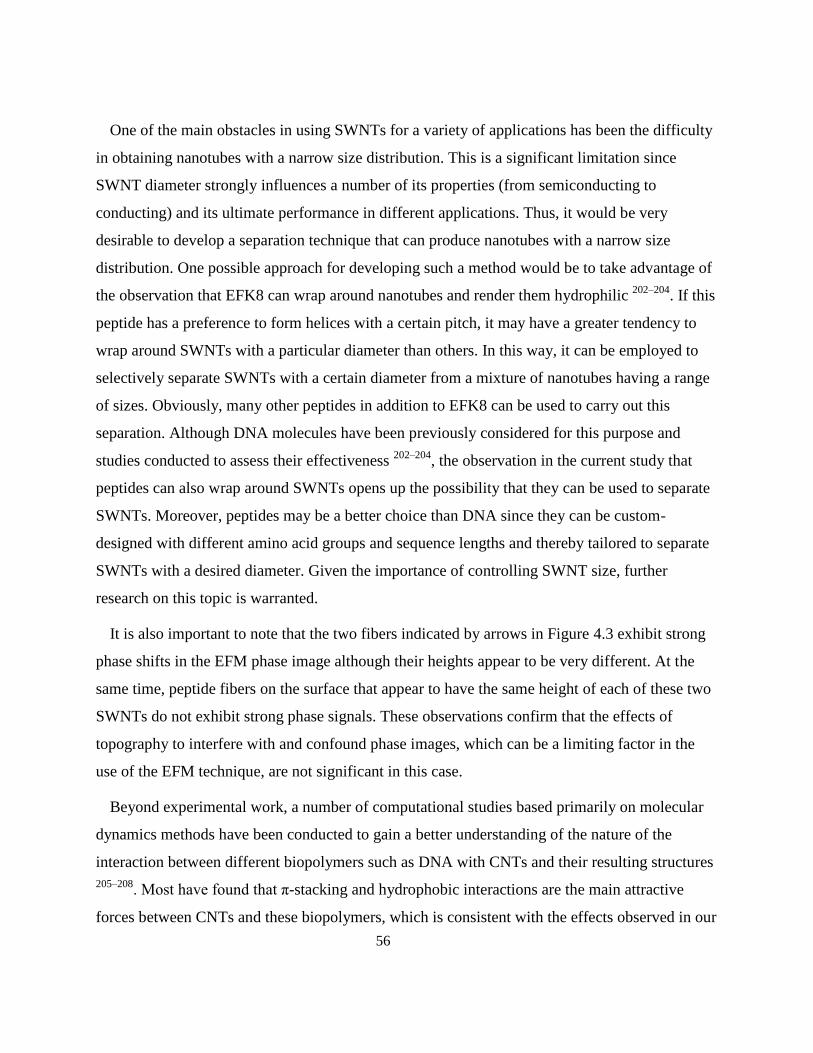
56
One of the main obstacles in using SWNTs for a variety of applications has been the difficulty
in obtaining nanotubes with a narrow size distribution. This is a significant limitation since
SWNT diameter strongly influences a number of its properties (from semiconducting to
conducting) and its ultimate performance in different applications. Thus, it would be very
desirable to develop a separation technique that can produce nanotubes with a narrow size
distribution. One possible approach for developing such a method would be to take advantage of
the observation that EFK8 can wrap around nanotubes and render them hydrophilic 202–204
. If this
peptide has a preference to form helices with a certain pitch, it may have a greater tendency to
wrap around SWNTs with a particular diameter than others. In this way, it can be employed to
selectively separate SWNTs with a certain diameter from a mixture of nanotubes having a range
of sizes. Obviously, many other peptides in addition to EFK8 can be used to carry out this
separation. Although DNA molecules have been previously considered for this purpose and
studies conducted to assess their effectiveness 202–204
, the observation in the current study that
peptides can also wrap around SWNTs opens up the possibility that they can be used to separate
SWNTs. Moreover, peptides may be a better choice than DNA since they can be custom-
designed with different amino acid groups and sequence lengths and thereby tailored to separate
SWNTs with a desired diameter. Given the importance of controlling SWNT size, further
research on this topic is warranted.
It is also important to note that the two fibers indicated by arrows in Figure 4.3 exhibit strong
phase shifts in the EFM phase image although their heights appear to be very different. At the
same time, peptide fibers on the surface that appear to have the same height of each of these two
SWNTs do not exhibit strong phase signals. These observations confirm that the effects of
topography to interfere with and confound phase images, which can be a limiting factor in the
use of the EFM technique, are not significant in this case.
Beyond experimental work, a number of computational studies based primarily on molecular
dynamics methods have been conducted to gain a better understanding of the nature of the
interaction between different biopolymers such as DNA with CNTs and their resulting structures
205–208. Most have found that π-stacking and hydrophobic interactions are the main attractive
forces between CNTs and these biopolymers, which is consistent with the effects observed in our
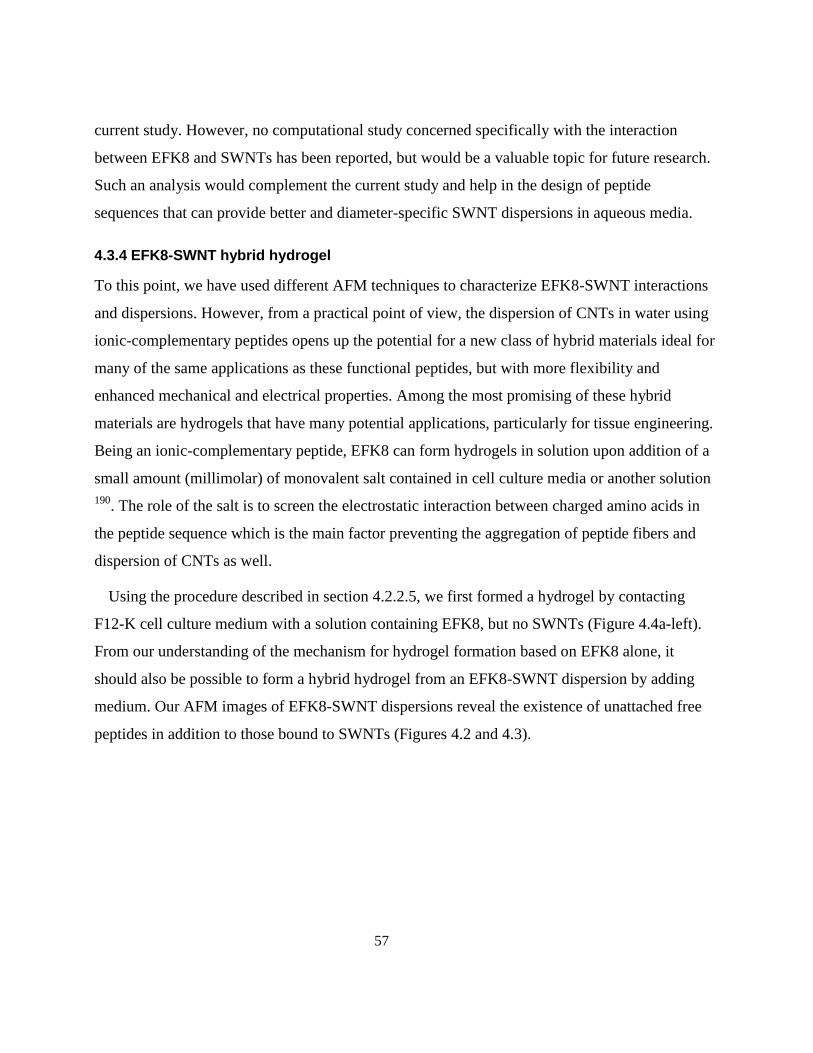
57
current study. However, no computational study concerned specifically with the interaction
between EFK8 and SWNTs has been reported, but would be a valuable topic for future research.
Such an analysis would complement the current study and help in the design of peptide
sequences that can provide better and diameter-specific SWNT dispersions in aqueous media.
4.3.4 EFK8-SWNT hybrid hydrogel
To this point, we have used different AFM techniques to characterize EFK8-SWNT interactions
and dispersions. However, from a practical point of view, the dispersion of CNTs in water using
ionic-complementary peptides opens up the potential for a new class of hybrid materials ideal for
many of the same applications as these functional peptides, but with more flexibility and
enhanced mechanical and electrical properties. Among the most promising of these hybrid
materials are hydrogels that have many potential applications, particularly for tissue engineering.
Being an ionic-complementary peptide, EFK8 can form hydrogels in solution upon addition of a
small amount (millimolar) of monovalent salt contained in cell culture media or another solution
190. The role of the salt is to screen the electrostatic interaction between charged amino acids in
the peptide sequence which is the main factor preventing the aggregation of peptide fibers and
dispersion of CNTs as well.
Using the procedure described in section 4.2.2.5, we first formed a hydrogel by contacting
F12-K cell culture medium with a solution containing EFK8, but no SWNTs (Figure 4.4a-left).
From our understanding of the mechanism for hydrogel formation based on EFK8 alone, it
should also be possible to form a hybrid hydrogel from an EFK8-SWNT dispersion by adding
medium. Our AFM images of EFK8-SWNT dispersions reveal the existence of unattached free
peptides in addition to those bound to SWNTs (Figures 4.2 and 4.3).
58
(a)
(b)
(c)
(d)
(e)
Figure 4.4 (a): EFK8 (left) and EFK8-SWNT hybrid (right) hydrogels. (b) Conceptual diagram of
hybrid hydrogel structure made up of a scaffold (in blue) of peptide fibers containing EFK8-
wrapped-SWNTs. SEM images of (c) EFK8 hydrogel, (d) EFK8-SWNT hydrogels. Highlighted
region in (d) is shown at higher magnification in (e).
5 mm
59
Both forms of the peptide contain charged amino acid groups that are exposed to the solution and
available to form bonds with charged groups in other peptide fibers and so should contribute to
hydrogel formation. The free peptides should operate exactly as they do in peptide-only
solutions, while the peptides wrapped around SWNTs are oriented with their hydrophilic sides
(containing charged amino acids) exposed to the solution. These ideas have been borne out by
the fact that we were able to form hydrogels following the procedure described in section 4.2.2.5
(Figure 4.4a-right). Figure 4.4b shows a schematic view of the hybrid hydrogel consisting of
peptide fibers forming the main scaffold (in blue) surrounding EFK8-wrapped-SWNTs. These
hydrogels are homogeneous and differ in appearance from those produced from EFK8 alone
primarily due to their gray color that arises from the entanglement of SWNTs in the peptide
scaffold. SEM images of the EFK8 and EFK8-SWNT hybrid hydrogels dried using the critical
point technique are shown in Figures 4.4c and d, respectively. The EFK8 hydrogel structure
consists of a network of peptide fibers entangled with each other similar to the structure observed
in real tissues of the body 190
. As shown in Figure 4.4c, the structure of the hybrid hydrogel
appears quite similar to the EFK8 hydrogel. Due to the fact that the SWNT and peptide fibers
have similar thicknesses and that the fibers become thicker when SWNTs are wrapped by the
peptide or hydrogels form, it is very difficult to distinguish between EFK8 fibers and SWNTs in
the SEM images. Figure 4.4e shows a magnified view of the highlighted region in Figure 4.4c. It
should be noted that some fibers (e.g., the one indicated by the blue dotted arrow) in this image
have much smaller diameters than others and may be SWNTs entangled in the peptide scaffold.
4.4 Conclusions
Scanning probe microscopy (SPM) examination of mica surfaces modified with EFK8 peptide
alone and with EFK8 and SWNTs together provides new evidence that this peptide can wrap
around the nanotubes, thereby rendering them hydrophilic and enabling their dispersion in
aqueous media. For the first time, nano-mechanical measurements during atomic force
microscopy (AFM) examination of the peptide-SWNT samples have been successfully used to
distinguish peptide fibers from SWNTs. The electric force microscopy (EFM) technique was also
successfully applied to identify SWNTs and distinguish them from self-assembled EFK8 peptide
fibers, something which was not possible using regular AFM imaging. Finally, by adding salt to

60
EFK8-SWNT dispersions, we showed that hybrid EFK8-SWNT hydrogels can be formed. Work
is currently underway to investigate the possibility of tuning their mechanical and electrical
properties such as stiffness and conductivity by appropriate adjustment of the experimental
conditions (e.g., peptide and SWNT concentration) during hydrogel formation. If successful, this
should have a large impact on a wide variety of applications, particularly tissue engineering.
61
Chapter 5
Peptide and Peptide-Carbon Nanotube Hydrogels as Scaffolds for
Tissue & 3D Tumor Engineering
Abstract
EFK8 peptide hydrogels and EFK8-SWNT hybrid hydrogels have been prepared and used to
culture NIH-3T3 fibroblast and A549 cancer cells. In the first part of the study, the effect of the
presence of SWNTs in the hydrogels on NIH-3T3 cell behavior cultured on hydrogels is
investigated. Inverted light and confocal microscopy images reveal that when the hydrogels
contain EFK8 only, the cells grow with spherical morphology and form isolated colonies. In the
presence of SWNT, cell behavior and growth change significantly to a stretched morphology and
spread individually and homogeneously over the surface. In addition, evidence shows that cells
tend to migrate into the hybrid hydrogels. Furthermore, cells exhibit a faster proliferation rate
when seeded on the hybrid hydrogel. An increase in the EFK8 solution concentration also leads
to an increase in the hydrogel compressive modulus whereas the addition of SWNTs does not
appear to have any effect on this property. Thus, the beneficial effect of SWNTs on the cell
behavior does not appear to be caused by modification of the compressive modulus and is
probably due to SWNTs serving as locations for cell anchorage that facilitate cell attachment,
spreading and migration. Cells encapsulated in both types of hydrogels show the same behavior
as in 2D cultures by forming colonies on EFK8 and spreading individually on the hybrid
hydrogel. In the second part of the study, the potential of EFK8 hydrogels to promote the
formation of spheroidal cancer cells is evaluated. The cells form spheroids when cultured on
EFK8 hydrogels prepared at a peptide concentration of 1.25 mg ml−1
, but show a more stretched
morphology and migratory phenotype when seeded on the stiffer hydrogel formed from 5 mg
ml−1
EFK8. On the other hand, cells adopt a stretched morphology with high mobility when
seeded on a hybrid EFK8-SWNT hydrogel formed from 1.25 mg ml−1
EFK8. Again, this
behavior can be attributed to the facilitating effect of SWNTs on cell adhesion and migration.
62
5.1 Introduction
Hydrogels are commonly used biomaterials for tissue engineering and 3D cell cultures due to
their high biocompatibility and the similarity of their physical and mechanical properties to that
of living tissue 83–87
. These similarities provide a compatible environment for cells and enable
their behavior to be similar to that observed in vivo. Hydrogels can also be modified chemically
to mimic living tissues so that they become more biocompatible and perform better in the body
83–85,88.
Different types of materials have been used so far to make hydrogel scaffolds. Synthetic
materials such as poly (lactic acid) (PLA) 8990
, poly (ethylene oxide) (PEO) 91
, poly (glycolic
acid) (PGA) 92
, poly (vinyl alcohol) (PVA) 9394
, poly (ethylene glycol) (PEG) 95
, as well as
polysaccharide hydrogels including hyaluronic acid (HA) 96
, chitosan 97
, agarose 98
and alginate
99 have been investigated for use with different types of tissues. Production of these synthetic
polymers is reproducible which makes them attractive for researchers. However, hydrogels
formed this way have major drawbacks such as large fiber/pore sizes, the use of toxic reagents
for gel formation, low degradation under physiological conditions, improper charge density, low
nutrient diffusion rate and acidic products due to degradation 100
. On the other hand, protein-
based hydrogels using collagen 101
, gelatin 102
, fibrin 103
, elastin 104
, silk fibroin 105
and
MatrigelTM
are more biocompatible and biodegradable and provide a better platform for cell
attachment and growth. However, they suffer from batch-to-batch variations and unwanted
contaminants such as growth factors, proteins and viruses which can interfere with cell function
83,100. On the whole, the best option would be to use a natural synthetic material. Self-assembling
peptides are very promising from this point of view. They are formed from amino acids and
found ubiquitously in the body; at the same time, they can be synthesized with precise control of
its chemical composition. This should minimize the effects of contaminants and enable the
distinction between the effects of different cues on cell behavior in the prepared scaffold. Their
biodegradation products are natural amino acids that are used in the body and can be
functionalized with different bioactive motifs for different cells and tissues. Also nano-sized
fibers and pores of these hydrogels mimic the structure of living tissues in the body. This
provides an environment that closely mimics in-vivo cell-cell and cell-scaffold interactions. In
63
addition, fiber crosslinking by which hydrogels form from these peptides does not require any
chemical additives, UV irradiation or heat treatment which can lead to lower biocompatibility,
unlike the situation with other biopolymer-based hydrogels. Finally, these peptide hydrogels can
be formed by injection which enables them to encapsulate cells for 3D cultures.
To date, different types of self-assembling peptide hydrogels have been used for tissue
engineering applications. RADA16-I hydrogels with the commercial name of PuraMatrixTM
have been used for different types of cells 100
. The advantage of this peptide compared with other
self-assembling peptides such as EFK8 is its similarity to the RGD tripeptide, a sequence within
fibronectin that mediates cell attachment. Furthermore, the sequence of this peptide has been
modified to extend its functionality and range of cells that can be seeded 106
. However, its
mechanical strength drops after neutralization to the physiological pH which leads to its
disruption when subjected to stress 107
. EFK8 is another type of self-assembling peptide with
better mechanical strength due to stronger hydrophobic interactions participating in self-
assembly process conferred by the presence of phenylalanine. We have previously shown that
EFK16-II and EFK8 peptides can disperse SWNTs and be combined to form hybrid peptide-
CNT hydrogels upon adding a small amount of salt 191,209
.
Another important application of hydrogels is for 3D cell cultures. Hydrogels have been used
as 3D scaffolds for drug discovery and 3D cancer tumor studies in vitro 86,87,108
. A 3D
environment for cancer cells for these applications appears to be necessary based on the results of
drug screening and tumor modelling. Reports show that the growth rate, morphology and drug
resistance of tumor cells in a 3D scaffold are different from that in a 2D environment 86,109–112
.
When cells are in vivo, both the extracellular matrix (ECM) and the physical properties of the
microenvironment contribute significantly to the behavior and gene expression of cancer cells. In
contrast with the classical theory of cancer which posits accumulated gene mutations to be the
main cause of cancer, tissue organization field theory (TOFT) introduces the cell-
microenvironment interaction as the starting point for cancer 113114
. It has even been reported that
the placement of malignant tumor cells in a normal microenvironment can revert the cancer cells
to a normal phenotype 115,116
. With this approach, not only the tumor microenvironment can be a
target for cancer therapy 117
but also bio-mimetic 3D scaffolds can serve as useful models of
64
healthy ECM to treat the tumors in vivo and avoid the local formation of new tumors 108,113118
.
For these reasons, attention in recent years has been increasingly focused on the tumor
microenvironment as an important controlling factor for cancer.
Although treatment of tumors through surgery, chemotherapy and radiation has progressed
tremendously, the ability to accurately predict the metastatic potential of a tumor is still missing
119. It has been well documented that tuning the scaffold stiffness can affect the growth and
differentiation of different types of cells 120–125
. Stiffness has been shown to be an important
characteristic of the microenvironment that affects tumor formation, progression and metastasis
127,128. Microenvironment stiffness affects these stages by regulating cell proliferation and
differentiation so that the cells become dysfunctional 119,129–131
. Thus, synthetic scaffolds with
tunable compressive modulus can serve as useful artificial 3D microenvironments to study
cancer cells, spheroids and tumors 132–136
.
In the current work, we have investigated the effect of the presence of SWNTs in EFK8
hydrogels on the NIH-3T3 fibroblast cell adherence, proliferation, migration and spreading as
well as the hydrogel compressive modulus. Also, the potential of EFK8 as a 3D scaffold with
tunable compressive modulus to study A549 cancer cell spheroid formation has been examined.
Finally, the effect of SWNT on the metastatic behavior of the cancer cells is investigated.
5.2 Materials and Methods
5.2.1 Materials
The ionic complementary peptide EFK8 with a sequence of FEFEFKFK where F corresponds to
phenylalanine, E to glutamic acid and K to lysine was used in this study. This peptide was
synthesized in our laboratory using an Aapptec Apex 396 peptide synthesizer. At neutral pH, F is
a neutral hydrophobic residue, while E and K are negatively and positively charged, respectively.
The peptide was protected by acetyl and amino groups at the N terminus and C-terminus,
respectively, to prevent end-to-end electrostatic interactions between peptides. EFK8 was
dissolved in pure water (18.2 MΩ; Millipore Milli-Q system) at a concentration of 0.5mg ml−1
to
prepare the peptide stock solution and then stored at 4°C before use. The metallic SWNTs
(carbon > 90%, carbon as SWNT > 77%) were purchased from Sigma-Aldrich Co (catalog#
65
727777, lot# MKBH7136V). NIH-3T3 and A549 cells were purchased from ATCC. DMEM
(high glucose) and F12-K medium solutions as well as fetal bovine serum (FBS) were obtained
from HyCloneTM
. Penicillin/streptomycin mixtures containing 10000 units penicillin and 10 mg
streptomycin, FluoroshieldTM
with DAPI and anti-β-catenin antibody produced from rabbits
(C2206) were acquired from Sigma-Aldrich. Actin GreenTM
488 ReadyProbes® reagent, Calcein
AM (C3099) and Ethidium Homodimer-1 (EthD-1) (E1169) were purchased from Life
technologies. AffiniPure Donkey anti-Rabbit IgG (Jackson Immunoresearch laboratories Inc)
was used as the secondary antibody.
5.2.2 Methods
5.2.2.1 Peptide synthesis
All amino acids (Fmoc protected), activator 2-(6-chloro-1H-benzotriazole-1-yl)-1,1,3,3-
tetramethylaminium hexafluorophosphate (HCTU) and Rink Amide-AM resin were obtained
from Aapptec LLC (USA). All other solutions were purchased from Acros Organics (USA). The
EFK8 peptide with a molecular weight of 1162.60 g mol−1
was synthesized in our laboratory
using the solid-phase peptide synthesis (SPPS) method using an Aapptec Apex 396 peptide
synthesizer (Aapptec LLC, USA) and then purified by repeated precipitation in cold ether. The
resulting peptide was then freeze-dried to yield a powder that was stored in a refrigerator.
Matrix-assisted laser desorption ionization time-of-flight mass spectroscopy (Q-TOF Ultima
Global, Waters, Milford, MA, USA) was used to measure the molar mass of the synthesized
peptide.
5.2.2.2 SWNT dispersion preparation
The stock suspensions were prepared by combining EFK8 and as-received SWNT (carbon >
90%, carbon as SWNT > 77%) together at a 1:1 mass ratio in pure water (18.2 MΩ; Millipore
Milli-Q system) to yield concentrations of 0.5 mg ml−1
of both the peptide and SWNTs. The
concentration of 0.5 mg ml−1
SWNT is based on the mass of as-received material and so may
include components that are not actual SWNT. The suspensions were then mixed for 1 hour
using a Qsonica XL-2000 probe sonicator at a power of 1W and centrifuged at a speed of 30,000
× g for 30 min to produce a supernatant that was decanted for hydrogel formation. The
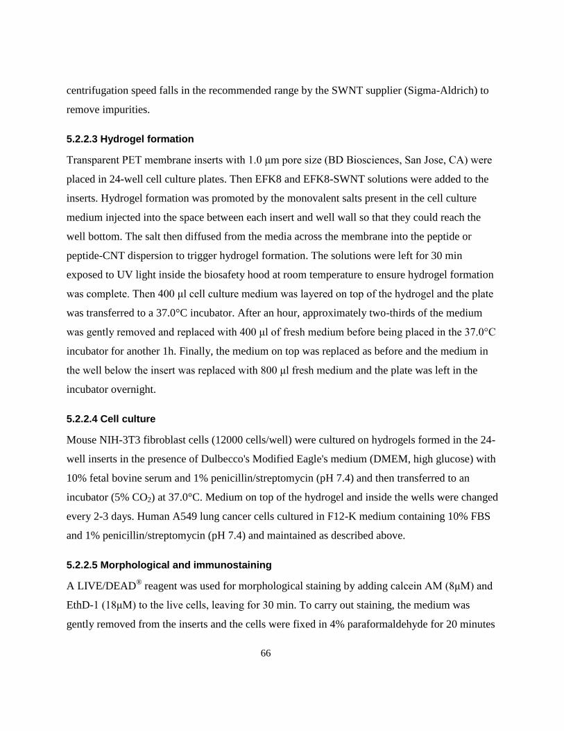
66
centrifugation speed falls in the recommended range by the SWNT supplier (Sigma-Aldrich) to
remove impurities.
5.2.2.3 Hydrogel formation
Transparent PET membrane inserts with 1.0 μm pore size (BD Biosciences, San Jose, CA) were
placed in 24-well cell culture plates. Then EFK8 and EFK8-SWNT solutions were added to the
inserts. Hydrogel formation was promoted by the monovalent salts present in the cell culture
medium injected into the space between each insert and well wall so that they could reach the
well bottom. The salt then diffused from the media across the membrane into the peptide or
peptide-CNT dispersion to trigger hydrogel formation. The solutions were left for 30 min
exposed to UV light inside the biosafety hood at room temperature to ensure hydrogel formation
was complete. Then 400 μl cell culture medium was layered on top of the hydrogel and the plate
was transferred to a 37.0°C incubator. After an hour, approximately two-thirds of the medium
was gently removed and replaced with 400 μl of fresh medium before being placed in the 37.0°C
incubator for another 1h. Finally, the medium on top was replaced as before and the medium in
the well below the insert was replaced with 800 μl fresh medium and the plate was left in the
incubator overnight.
5.2.2.4 Cell culture
Mouse NIH-3T3 fibroblast cells (12000 cells/well) were cultured on hydrogels formed in the 24-
well inserts in the presence of Dulbecco's Modified Eagle's medium (DMEM, high glucose) with
10% fetal bovine serum and 1% penicillin/streptomycin (pH 7.4) and then transferred to an
incubator (5% CO2) at 37.0°C. Medium on top of the hydrogel and inside the wells were changed
every 2-3 days. Human A549 lung cancer cells cultured in F12-K medium containing 10% FBS
and 1% penicillin/streptomycin (pH 7.4) and maintained as described above.
5.2.2.5 Morphological and immunostaining
A LIVE/DEAD® reagent was used for morphological staining by adding calcein AM (8μM) and
EthD-1 (18μM) to the live cells, leaving for 30 min. To carry out staining, the medium was
gently removed from the inserts and the cells were fixed in 4% paraformaldehyde for 20 minutes
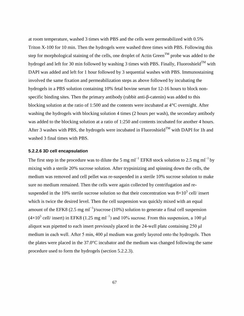
67
at room temperature, washed 3 times with PBS and the cells were permeabilized with 0.5%
Triton X-100 for 10 min. Then the hydrogels were washed three times with PBS. Following this
step for morphological staining of the cells, one droplet of Actin GreenTM
probe was added to the
hydrogel and left for 30 min followed by washing 3 times with PBS. Finally, FluoroshieldTM
with
DAPI was added and left for 1 hour followed by 3 sequential washes with PBS. Immunostaining
involved the same fixation and permeabilization steps as above followed by incubating the
hydrogels in a PBS solution containing 10% fetal bovine serum for 12-16 hours to block non-
specific binding sites. Then the primary antibody (rabbit anti-β-catenin) was added to this
blocking solution at the ratio of 1:500 and the contents were incubated at 4°C overnight. After
washing the hydrogels with blocking solution 4 times (2 hours per wash), the secondary antibody
was added to the blocking solution at a ratio of 1:250 and contents incubated for another 4 hours.
After 3 washes with PBS, the hydrogels were incubated in FluoroshieldTM
with DAPI for 1h and
washed 3 final times with PBS.
5.2.2.6 3D cell encapsulation
The first step in the procedure was to dilute the 5 mg ml−1
EFK8 stock solution to 2.5 mg ml−1
by
mixing with a sterile 20% sucrose solution. After trypsinizing and spinning down the cells, the
medium was removed and cell pellet was re-suspended in a sterile 10% sucrose solution to make
sure no medium remained. Then the cells were again collected by centrifugation and re-
suspended in the 10% sterile sucrose solution so that their concentration was 8×10⁵ cell/ insert
which is twice the desired level. Then the cell suspension was quickly mixed with an equal
amount of the EFK8 (2.5 mg ml−1
)/sucrose (10%) solution to generate a final cell suspension
(4×10⁵ cell/ insert) in EFK8 (1.25 mg ml
−1) and 10% sucrose. From this suspension, a 100 μl
aliquot was pipetted to each insert previously placed in the 24-well plate containing 250 μl
medium in each well. After 5 min, 400 μl medium was gently layered onto the hydrogels. Then
the plates were placed in the 37.0°C incubator and the medium was changed following the same
procedure used to form the hydrogels (section 5.2.2.3).
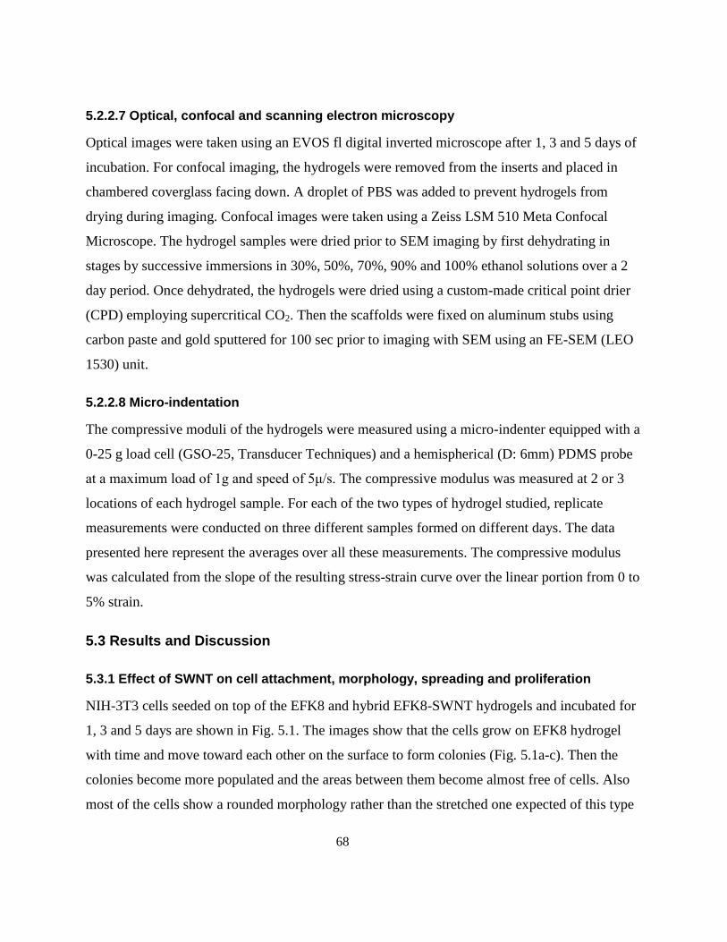
68
5.2.2.7 Optical, confocal and scanning electron microscopy
Optical images were taken using an EVOS fl digital inverted microscope after 1, 3 and 5 days of
incubation. For confocal imaging, the hydrogels were removed from the inserts and placed in
chambered coverglass facing down. A droplet of PBS was added to prevent hydrogels from
drying during imaging. Confocal images were taken using a Zeiss LSM 510 Meta Confocal
Microscope. The hydrogel samples were dried prior to SEM imaging by first dehydrating in
stages by successive immersions in 30%, 50%, 70%, 90% and 100% ethanol solutions over a 2
day period. Once dehydrated, the hydrogels were dried using a custom-made critical point drier
(CPD) employing supercritical CO2. Then the scaffolds were fixed on aluminum stubs using
carbon paste and gold sputtered for 100 sec prior to imaging with SEM using an FE-SEM (LEO
1530) unit.
5.2.2.8 Micro-indentation
The compressive moduli of the hydrogels were measured using a micro-indenter equipped with a
0-25 g load cell (GSO-25, Transducer Techniques) and a hemispherical (D: 6mm) PDMS probe
at a maximum load of 1g and speed of 5μ/s. The compressive modulus was measured at 2 or 3
locations of each hydrogel sample. For each of the two types of hydrogel studied, replicate
measurements were conducted on three different samples formed on different days. The data
presented here represent the averages over all these measurements. The compressive modulus
was calculated from the slope of the resulting stress-strain curve over the linear portion from 0 to
5% strain.
5.3 Results and Discussion
5.3.1 Effect of SWNT on cell attachment, morphology, spreading and proliferation
NIH-3T3 cells seeded on top of the EFK8 and hybrid EFK8-SWNT hydrogels and incubated for
1, 3 and 5 days are shown in Fig. 5.1. The images show that the cells grow on EFK8 hydrogel
with time and move toward each other on the surface to form colonies (Fig. 5.1a-c). Then the
colonies become more populated and the areas between them become almost free of cells. Also
most of the cells show a rounded morphology rather than the stretched one expected of this type
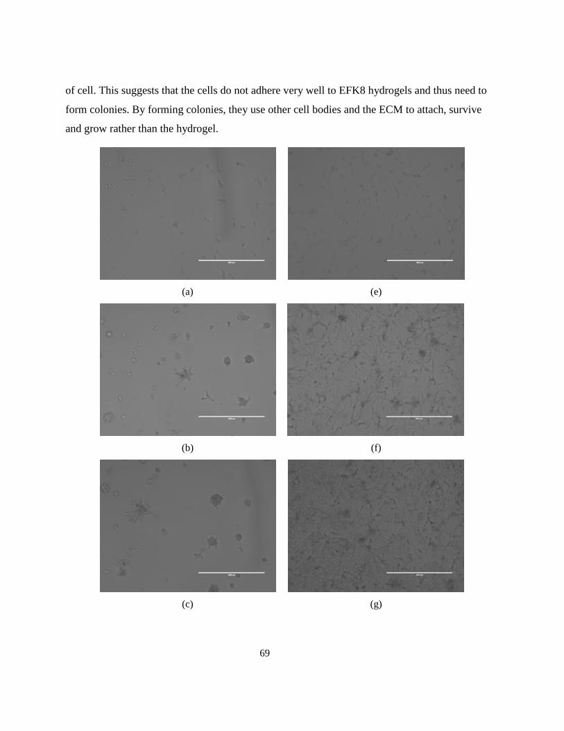
69
of cell. This suggests that the cells do not adhere very well to EFK8 hydrogels and thus need to
form colonies. By forming colonies, they use other cell bodies and the ECM to attach, survive
and grow rather than the hydrogel.
(a)
(e)
(b)
(f)
(c)
(g)
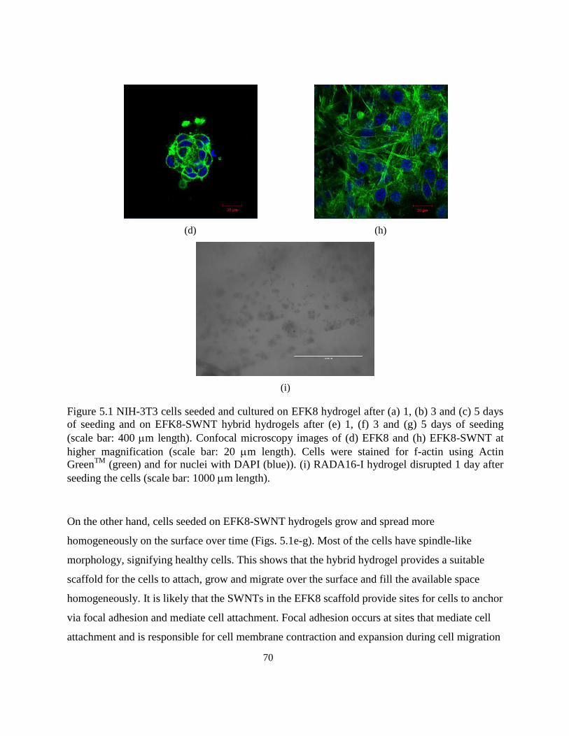
70
(d)
(h)
(i)
Figure 5.1 NIH-3T3 cells seeded and cultured on EFK8 hydrogel after (a) 1, (b) 3 and (c) 5 days
of seeding and on EFK8-SWNT hybrid hydrogels after (e) 1, (f) 3 and (g) 5 days of seeding
(scale bar: 400 m length). Confocal microscopy images of (d) EFK8 and (h) EFK8-SWNT at
higher magnification (scale bar: 20 m length). Cells were stained for f-actin using Actin
GreenTM
(green) and for nuclei with DAPI (blue)). (i) RADA16-I hydrogel disrupted 1 day after
seeding the cells (scale bar: 1000 m length).
On the other hand, cells seeded on EFK8-SWNT hydrogels grow and spread more
homogeneously on the surface over time (Figs. 5.1e-g). Most of the cells have spindle-like
morphology, signifying healthy cells. This shows that the hybrid hydrogel provides a suitable
scaffold for the cells to attach, grow and migrate over the surface and fill the available space
homogeneously. It is likely that the SWNTs in the EFK8 scaffold provide sites for cells to anchor
via focal adhesion and mediate cell attachment. Focal adhesion occurs at sites that mediate cell
attachment and is responsible for cell membrane contraction and expansion during cell migration
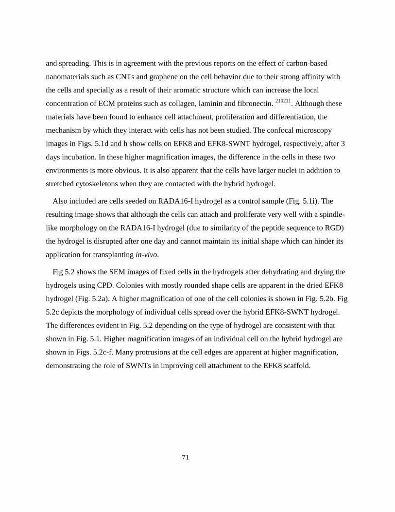
71
and spreading. This is in agreement with the previous reports on the effect of carbon-based
nanomaterials such as CNTs and graphene on the cell behavior due to their strong affinity with
the cells and specially as a result of their aromatic structure which can increase the local
concentration of ECM proteins such as collagen, laminin and fibronectin. 210211
. Although these
materials have been found to enhance cell attachment, proliferation and differentiation, the
mechanism by which they interact with cells has not been studied. The confocal microscopy
images in Figs. 5.1d and h show cells on EFK8 and EFK8-SWNT hydrogel, respectively, after 3
days incubation. In these higher magnification images, the difference in the cells in these two
environments is more obvious. It is also apparent that the cells have larger nuclei in addition to
stretched cytoskeletons when they are contacted with the hybrid hydrogel.
Also included are cells seeded on RADA16-I hydrogel as a control sample (Fig. 5.1i). The
resulting image shows that although the cells can attach and proliferate very well with a spindle-
like morphology on the RADA16-I hydrogel (due to similarity of the peptide sequence to RGD)
the hydrogel is disrupted after one day and cannot maintain its initial shape which can hinder its
application for transplanting in-vivo.
Fig 5.2 shows the SEM images of fixed cells in the hydrogels after dehydrating and drying the
hydrogels using CPD. Colonies with mostly rounded shape cells are apparent in the dried EFK8
hydrogel (Fig. 5.2a). A higher magnification of one of the cell colonies is shown in Fig. 5.2b. Fig
5.2c depicts the morphology of individual cells spread over the hybrid EFK8-SWNT hydrogel.
The differences evident in Fig. 5.2 depending on the type of hydrogel are consistent with that
shown in Fig. 5.1. Higher magnification images of an individual cell on the hybrid hydrogel are
shown in Figs. 5.2c-f. Many protrusions at the cell edges are apparent at higher magnification,
demonstrating the role of SWNTs in improving cell attachment to the EFK8 scaffold.
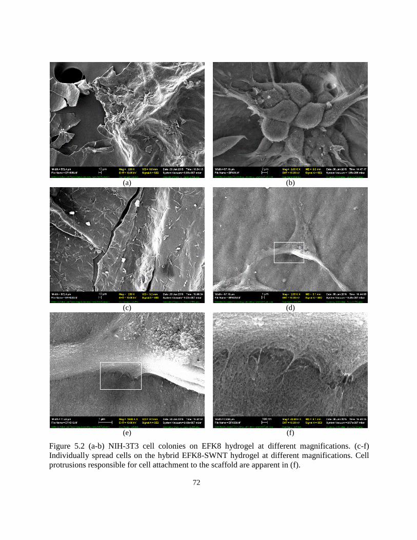
72
(a)
(b)
(c)
(d)
(e)
(f)
Figure 5.2 (a-b) NIH-3T3 cell colonies on EFK8 hydrogel at different magnifications. (c-f)
Individually spread cells on the hybrid EFK8-SWNT hydrogel at different magnifications. Cell
protrusions responsible for cell attachment to the scaffold are apparent in (f).
73
Comparison of the images in Fig. 5.1 suggests that cells grow faster on the EFK8-SWNT
hydrogel and more cells are living in this scaffold after 5 days. To compare the proliferation rate
on the two hydrogels, the gels were disrupted and the cells collected and counted using a
hemocytometer after 1, 3 and 5 days of culture (Figure 5.3). This analysis shows that the number
of cells is almost the same on both hydrogels 1 day after seeding. However, over the period from
day 1 to day 3 after seeding, cells grow and proliferate faster on the hybrid hydrogel, again
showing the effect of SWNTs on the proliferation of the cells. The difference in the number of
cells continues to grow over the period from day 3 to day 5. Based on the corresponding optical
images, the hybrid hydrogel is completely covered with cells by day 5 while considerable free
space is available on the EFK8 hydrogel after the same incubation time.
Figure 5.3 NIH-3T3 cell proliferation on the EFK8 and EFK8-SWNT hydrogels incubated for 1,
3 and 5 days after seeding. All data represent mean ± s.d. *P < 0.05.
Thus, based on these microscopy images and cell counting data, the presence of SWNTs in the
EFK8 hydrogel appears to significantly improve cell behavior in terms of attachment,
morphology, spreading and proliferation rate.
0
50000
100000
150000
200000
250000
300000
Day 1 Day 3 Day 5
Ce
lls
EFK8
EFK8-SWNT
*
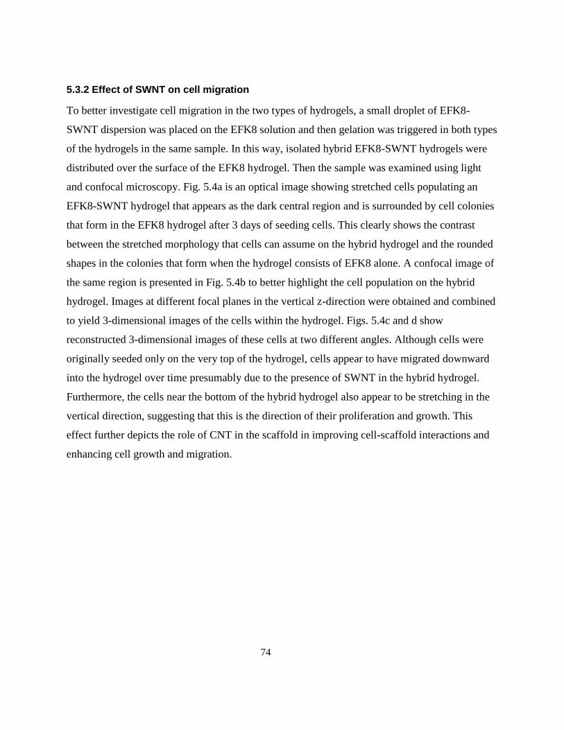
74
5.3.2 Effect of SWNT on cell migration
To better investigate cell migration in the two types of hydrogels, a small droplet of EFK8-
SWNT dispersion was placed on the EFK8 solution and then gelation was triggered in both types
of the hydrogels in the same sample. In this way, isolated hybrid EFK8-SWNT hydrogels were
distributed over the surface of the EFK8 hydrogel. Then the sample was examined using light
and confocal microscopy. Fig. 5.4a is an optical image showing stretched cells populating an
EFK8-SWNT hydrogel that appears as the dark central region and is surrounded by cell colonies
that form in the EFK8 hydrogel after 3 days of seeding cells. This clearly shows the contrast
between the stretched morphology that cells can assume on the hybrid hydrogel and the rounded
shapes in the colonies that form when the hydrogel consists of EFK8 alone. A confocal image of
the same region is presented in Fig. 5.4b to better highlight the cell population on the hybrid
hydrogel. Images at different focal planes in the vertical z-direction were obtained and combined
to yield 3-dimensional images of the cells within the hydrogel. Figs. 5.4c and d show
reconstructed 3-dimensional images of these cells at two different angles. Although cells were
originally seeded only on the very top of the hydrogel, cells appear to have migrated downward
into the hydrogel over time presumably due to the presence of SWNT in the hybrid hydrogel.
Furthermore, the cells near the bottom of the hybrid hydrogel also appear to be stretching in the
vertical direction, suggesting that this is the direction of their proliferation and growth. This
effect further depicts the role of CNT in the scaffold in improving cell-scaffold interactions and
enhancing cell growth and migration.
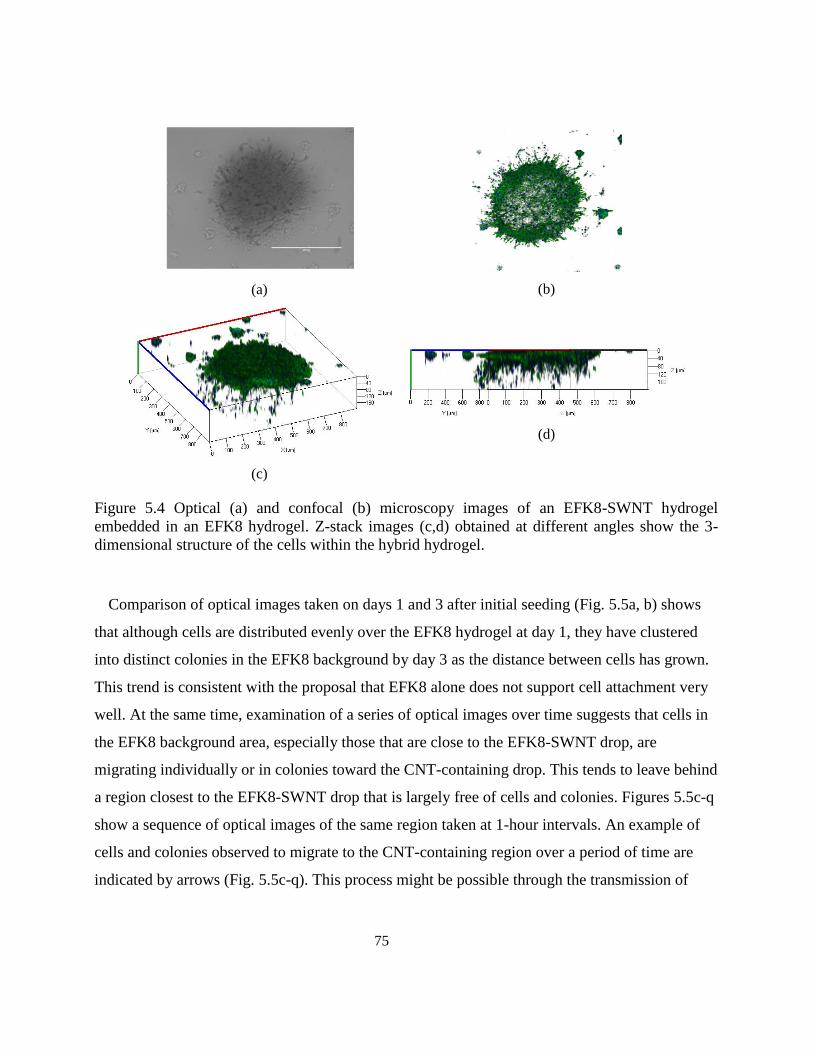
75
(a)
(b)
(c)
(d)
Figure 5.4 Optical (a) and confocal (b) microscopy images of an EFK8-SWNT hydrogel
embedded in an EFK8 hydrogel. Z-stack images (c,d) obtained at different angles show the 3-
dimensional structure of the cells within the hybrid hydrogel.
Comparison of optical images taken on days 1 and 3 after initial seeding (Fig. 5.5a, b) shows
that although cells are distributed evenly over the EFK8 hydrogel at day 1, they have clustered
into distinct colonies in the EFK8 background by day 3 as the distance between cells has grown.
This trend is consistent with the proposal that EFK8 alone does not support cell attachment very
well. At the same time, examination of a series of optical images over time suggests that cells in
the EFK8 background area, especially those that are close to the EFK8-SWNT drop, are
migrating individually or in colonies toward the CNT-containing drop. This tends to leave behind
a region closest to the EFK8-SWNT drop that is largely free of cells and colonies. Figures 5.5c-q
show a sequence of optical images of the same region taken at 1-hour intervals. An example of
cells and colonies observed to migrate to the CNT-containing region over a period of time are
indicated by arrows (Fig. 5.5c-q). This process might be possible through the transmission of
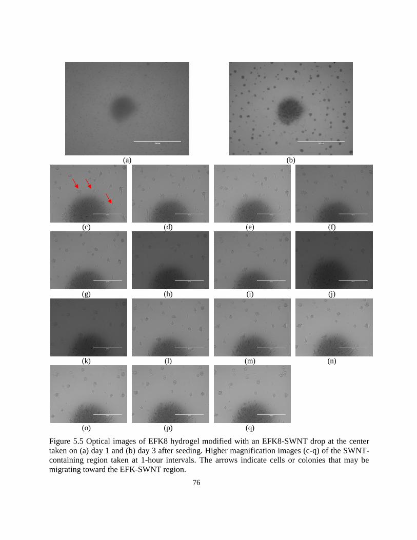
76
(a)
(b)
(c)
(d)
(e)
(f)
(g)
(h)
(i)
(j)
(k)
(l)
(m)
(n)
(o)
(p)
(q)
Figure 5.5 Optical images of EFK8 hydrogel modified with an EFK8-SWNT drop at the center
taken on (a) day 1 and (b) day 3 after seeding. Higher magnification images (c-q) of the SWNT-
containing region taken at 1-hour intervals. The arrows indicate cells or colonies that may be
migrating toward the EFK-SWNT region.
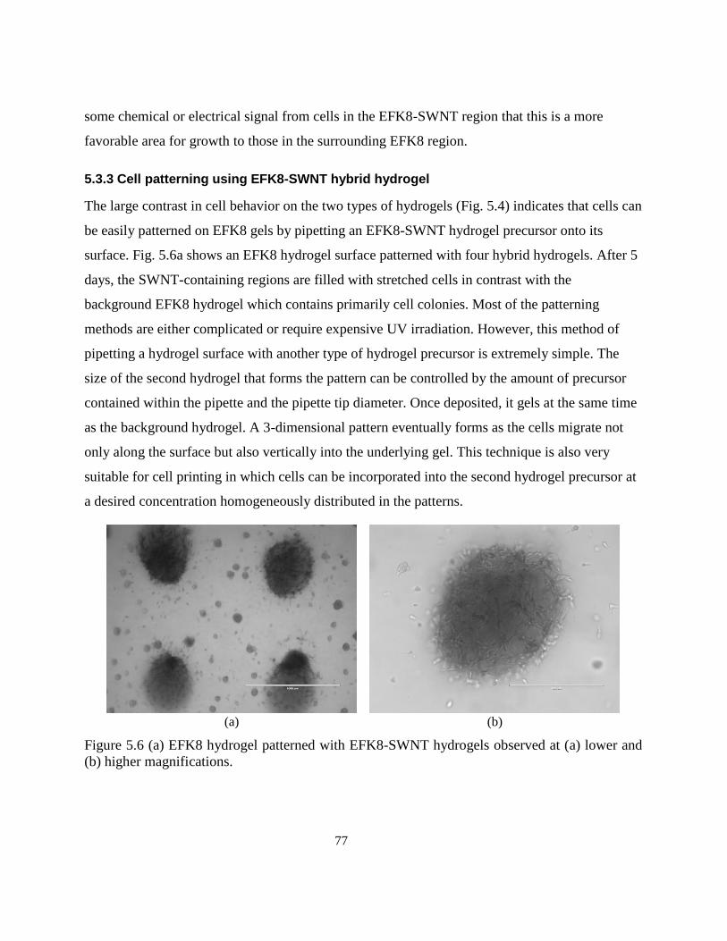
77
some chemical or electrical signal from cells in the EFK8-SWNT region that this is a more
favorable area for growth to those in the surrounding EFK8 region.
5.3.3 Cell patterning using EFK8-SWNT hybrid hydrogel
The large contrast in cell behavior on the two types of hydrogels (Fig. 5.4) indicates that cells can
be easily patterned on EFK8 gels by pipetting an EFK8-SWNT hydrogel precursor onto its
surface. Fig. 5.6a shows an EFK8 hydrogel surface patterned with four hybrid hydrogels. After 5
days, the SWNT-containing regions are filled with stretched cells in contrast with the
background EFK8 hydrogel which contains primarily cell colonies. Most of the patterning
methods are either complicated or require expensive UV irradiation. However, this method of
pipetting a hydrogel surface with another type of hydrogel precursor is extremely simple. The
size of the second hydrogel that forms the pattern can be controlled by the amount of precursor
contained within the pipette and the pipette tip diameter. Once deposited, it gels at the same time
as the background hydrogel. A 3-dimensional pattern eventually forms as the cells migrate not
only along the surface but also vertically into the underlying gel. This technique is also very
suitable for cell printing in which cells can be incorporated into the second hydrogel precursor at
a desired concentration homogeneously distributed in the patterns.
(a)
(b)
Figure 5.6 (a) EFK8 hydrogel patterned with EFK8-SWNT hydrogels observed at (a) lower and
(b) higher magnifications.
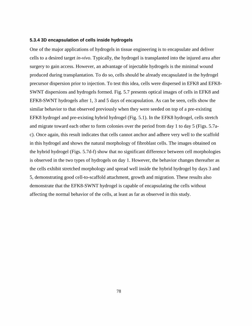
78
5.3.4 3D encapsulation of cells inside hydrogels
One of the major applications of hydrogels in tissue engineering is to encapsulate and deliver
cells to a desired target in-vivo. Typically, the hydrogel is transplanted into the injured area after
surgery to gain access. However, an advantage of injectable hydrogels is the minimal wound
produced during transplantation. To do so, cells should be already encapsulated in the hydrogel
precursor dispersion prior to injection. To test this idea, cells were dispersed in EFK8 and EFK8-
SWNT dispersions and hydrogels formed. Fig. 5.7 presents optical images of cells in EFK8 and
EFK8-SWNT hydrogels after 1, 3 and 5 days of encapsulation. As can be seen, cells show the
similar behavior to that observed previously when they were seeded on top of a pre-existing
EFK8 hydrogel and pre-existing hybrid hydrogel (Fig. 5.1). In the EFK8 hydrogel, cells stretch
and migrate toward each other to form colonies over the period from day 1 to day 5 (Figs. 5.7a-
c). Once again, this result indicates that cells cannot anchor and adhere very well to the scaffold
in this hydrogel and shows the natural morphology of fibroblast cells. The images obtained on
the hybrid hydrogel (Figs. 5.7d-f) show that no significant difference between cell morphologies
is observed in the two types of hydrogels on day 1. However, the behavior changes thereafter as
the cells exhibit stretched morphology and spread well inside the hybrid hydrogel by days 3 and
5, demonstrating good cell-to-scaffold attachment, growth and migration. These results also
demonstrate that the EFK8-SWNT hydrogel is capable of encapsulating the cells without
affecting the normal behavior of the cells, at least as far as observed in this study.
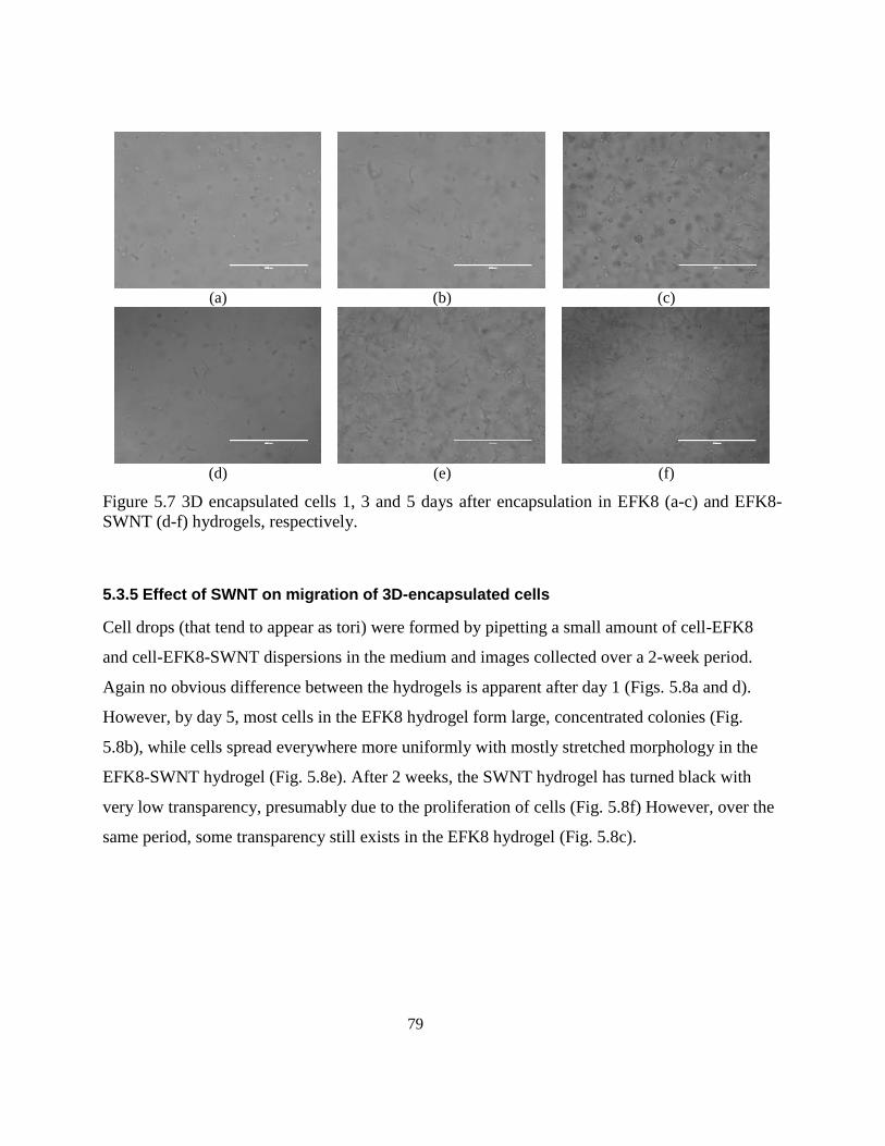
79
(a)
(b)
(c)
(d)
(e)
(f)
Figure 5.7 3D encapsulated cells 1, 3 and 5 days after encapsulation in EFK8 (a-c) and EFK8-
SWNT (d-f) hydrogels, respectively.
5.3.5 Effect of SWNT on migration of 3D-encapsulated cells
Cell drops (that tend to appear as tori) were formed by pipetting a small amount of cell-EFK8
and cell-EFK8-SWNT dispersions in the medium and images collected over a 2-week period.
Again no obvious difference between the hydrogels is apparent after day 1 (Figs. 5.8a and d).
However, by day 5, most cells in the EFK8 hydrogel form large, concentrated colonies (Fig.
5.8b), while cells spread everywhere more uniformly with mostly stretched morphology in the
EFK8-SWNT hydrogel (Fig. 5.8e). After 2 weeks, the SWNT hydrogel has turned black with
very low transparency, presumably due to the proliferation of cells (Fig. 5.8f) However, over the
same period, some transparency still exists in the EFK8 hydrogel (Fig. 5.8c).
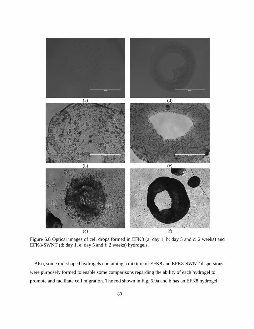
80
(a)
(d)
(b)
(e)
(c)
(f)
Figure 5.8 Optical images of cell drops formed in EFK8 (a: day 1, b: day 5 and c: 2 weeks) and
EFK8-SWNT (d: day 1, e: day 5 and f: 2 weeks) hydrogels.
Also, some rod-shaped hydrogels containing a mixture of EFK8 and EFK8-SWNT dispersions
were purposely formed to enable some comparisons regarding the ability of each hydrogel to
promote and facilitate cell migration. The rod shown in Fig. 5.9a and b has an EFK8 hydrogel
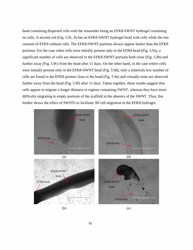
81
head containing dispersed cells with the remainder being an EFK8-SWNT hydrogel containing
no cells. A second rod (Fig. 5.9c, d) has an EFK8-SWNT hydrogel head with cells while the rest
consists of EFK8 without cells. The EFK8-SWNT portions always appear darker than the EFK8
portions. For the case when cells were initially present only in the EFK8 head (Fig. 5.9a), a
significant number of cells are observed in the EFK8-SWNT portions both close (Fig. 5.9b) and
further away (Fig. 5.9c) from the head after 11 days. On the other hand, in the case where cells
were initially present only in the EFK8-SWNT head (Fig. 5.9d), only a relatively low number of
cells are found in the EFK8 portion close to the head (Fig. 5.9e) and virtually none are observed
further away from the head (Fig. 5.9f) after 11 days. Taken together, these results suggest that
cells appear to migrate a longer distance in regions containing SWNT, whereas they have more
difficulty migrating to empty portions of the scaffold in the absence of the SWNT. Thus, this
further shows the effect of SWNTs to facilitate 3D cell migration in the EFK8 hydrogel.
(a)
(d)
(b)
(e)
EFK8 head
EFK8 body
EFK8-SWNT
head
EFK8-SWNT
body
EFK8 head
EFK8-SWNT
body
EFK8 body
EFK8-SWNT
head
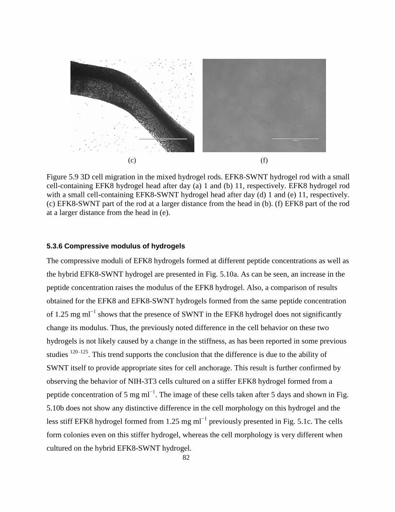
82
(c)
(f)
Figure 5.9 3D cell migration in the mixed hydrogel rods. EFK8-SWNT hydrogel rod with a small
cell-containing EFK8 hydrogel head after day (a) 1 and (b) 11, respectively. EFK8 hydrogel rod
with a small cell-containing EFK8-SWNT hydrogel head after day (d) 1 and (e) 11, respectively.
(c) EFK8-SWNT part of the rod at a larger distance from the head in (b). (f) EFK8 part of the rod
at a larger distance from the head in (e).
5.3.6 Compressive modulus of hydrogels
The compressive moduli of EFK8 hydrogels formed at different peptide concentrations as well as
the hybrid EFK8-SWNT hydrogel are presented in Fig. 5.10a. As can be seen, an increase in the
peptide concentration raises the modulus of the EFK8 hydrogel. Also, a comparison of results
obtained for the EFK8 and EFK8-SWNT hydrogels formed from the same peptide concentration
of 1.25 mg ml−1
shows that the presence of SWNT in the EFK8 hydrogel does not significantly
change its modulus. Thus, the previously noted difference in the cell behavior on these two
hydrogels is not likely caused by a change in the stiffness, as has been reported in some previous
studies 120–125
. This trend supports the conclusion that the difference is due to the ability of
SWNT itself to provide appropriate sites for cell anchorage. This result is further confirmed by
observing the behavior of NIH-3T3 cells cultured on a stiffer EFK8 hydrogel formed from a
peptide concentration of 5 mg ml−1
. The image of these cells taken after 5 days and shown in Fig.
5.10b does not show any distinctive difference in the cell morphology on this hydrogel and the
less stiff EFK8 hydrogel formed from 1.25 mg ml−1
previously presented in Fig. 5.1c. The cells
form colonies even on this stiffer hydrogel, whereas the cell morphology is very different when
cultured on the hybrid EFK8-SWNT hydrogel.
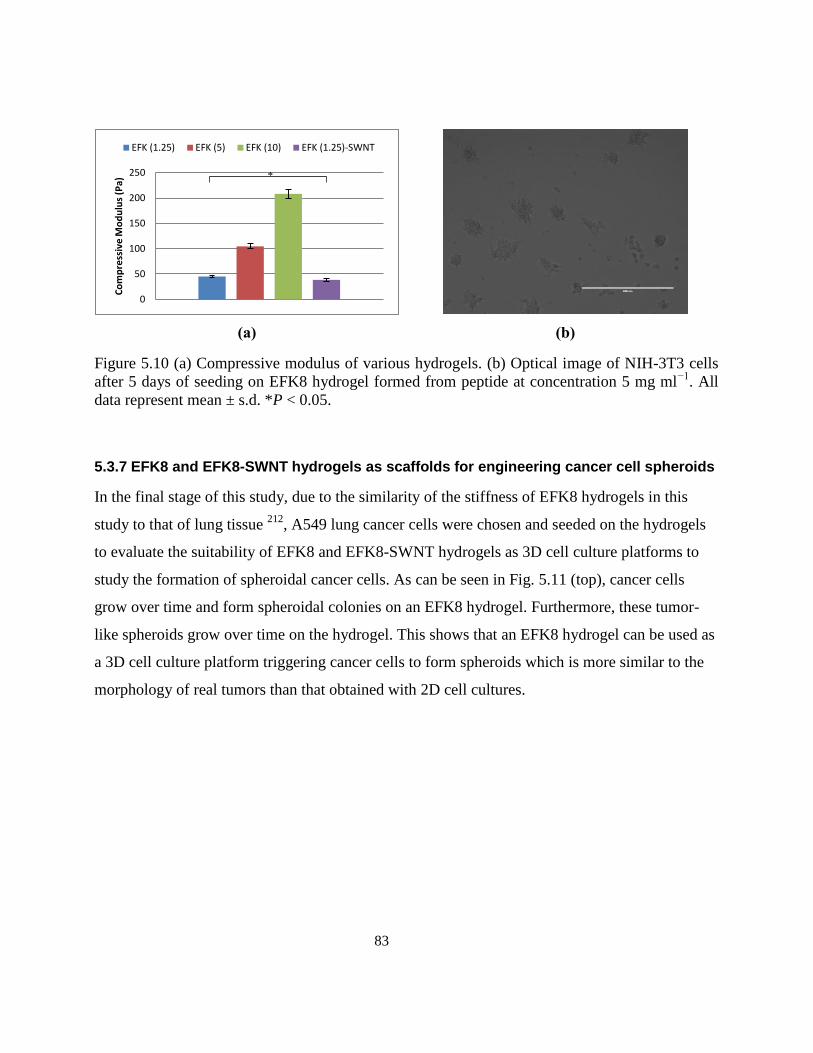
83
(a)
(b)
Figure 5.10 (a) Compressive modulus of various hydrogels. (b) Optical image of NIH-3T3 cells
after 5 days of seeding on EFK8 hydrogel formed from peptide at concentration 5 mg ml−1
. All
data represent mean ± s.d. *P < 0.05.
5.3.7 EFK8 and EFK8-SWNT hydrogels as scaffolds for engineering cancer cell spheroids
In the final stage of this study, due to the similarity of the stiffness of EFK8 hydrogels in this
study to that of lung tissue 212
, A549 lung cancer cells were chosen and seeded on the hydrogels
to evaluate the suitability of EFK8 and EFK8-SWNT hydrogels as 3D cell culture platforms to
study the formation of spheroidal cancer cells. As can be seen in Fig. 5.11 (top), cancer cells
grow over time and form spheroidal colonies on an EFK8 hydrogel. Furthermore, these tumor-
like spheroids grow over time on the hydrogel. This shows that an EFK8 hydrogel can be used as
a 3D cell culture platform triggering cancer cells to form spheroids which is more similar to the
morphology of real tumors than that obtained with 2D cell cultures.
0
50
100
150
200
250
Co
mp
ress
ive
Mo
du
lus
(Pa)
EFK (1.25) EFK (5) EFK (10) EFK (1.25)-SWNT
*
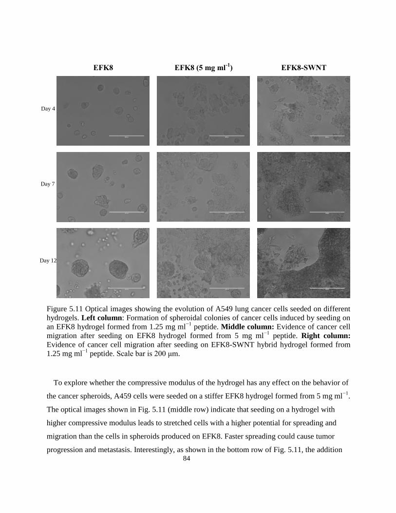
84
EFK8
EFK8 (5 mg ml-1
)
EFK8-SWNT
Figure 5.11 Optical images showing the evolution of A549 lung cancer cells seeded on different
hydrogels. Left column: Formation of spheroidal colonies of cancer cells induced by seeding on
an EFK8 hydrogel formed from 1.25 mg ml−1
peptide. Middle column: Evidence of cancer cell
migration after seeding on EFK8 hydrogel formed from 5 mg ml−1
peptide. Right column:
Evidence of cancer cell migration after seeding on EFK8-SWNT hybrid hydrogel formed from
1.25 mg ml−1
peptide. Scale bar is 200 μm.
To explore whether the compressive modulus of the hydrogel has any effect on the behavior of
the cancer spheroids, A459 cells were seeded on a stiffer EFK8 hydrogel formed from 5 mg ml−1
.
The optical images shown in Fig. 5.11 (middle row) indicate that seeding on a hydrogel with
higher compressive modulus leads to stretched cells with a higher potential for spreading and
migration than the cells in spheroids produced on EFK8. Faster spreading could cause tumor
progression and metastasis. Interestingly, as shown in the bottom row of Fig. 5.11, the addition
Day 4
Day 7
Day 12
85
of SWNTs to the EFK8 hydrogel formed from 1.25 mg ml−1
peptide leads to similar cell
morphology (stretched cells with long protrusions) to that observed on EFK8 alone when formed
from 5 mg ml−1
peptide. Earlier in this study, we showed that the presence of SWNTs in an
EFK8 hydrogel improved normal cell attachment, spreading and migration. Thus, the behavior of
A549 cells observed in Fig. 5.11 when seeded on EFK8-SWNT likely reflects the combined
effects of the binding regions in the tumor microenvironment and the compressive modulus.
Fig. 5.12 a and b shows cells that have been stained using the Live/Dead® assay conducted on
EFK8 hydrogels formed from both 1.25 and 5 mg ml−1
peptide. In these images, the difference in
geometry of cell spheroids present on the hydrogel formed at 1.25 mg ml−1
peptide (Fig. 5.12a)
to that of the stretched cells present on the hydrogel formed at the higher peptide concentration
(Fig. 5.12 b) is obvious. Immunostaining of β-catenin normally concentrated at the cell-cell
junctions using anti-β-catenin and of the cell nucleus using DAPI was also conducted. In the case
of the EFK8 hydrogel formed from 5 mg ml−1
peptide (Fig. 5.12 d) and the EFK8-SWNT
hydrogel (Fig. 5.12 e), some cells at the border of the tumors contain less concentrated green β-
catenin on the edges and do not have sharp polygonal boundary that are characteristic of compact
cells in colonies. This suggests that these cells are not strongly attached to their neighbor cells
which should facilitate cell dissemination and metastasis. On the other hand, cells seeded on the
EFK8 hydrogel formed from 1.25 mg ml−1
peptide form spheroids that pack together with sharp
polygonal boundaries and have a more concentrated green β-catenin color on the edges (Fig. 5.12
c).
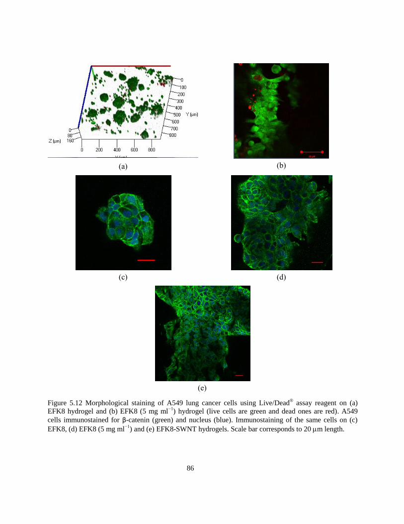
86
(a)
(b)
(c)
(d)
(e)
Figure 5.12 Morphological staining of A549 lung cancer cells using Live/Dead® assay reagent on (a)
EFK8 hydrogel and (b) EFK8 (5 mg ml−1
) hydrogel (live cells are green and dead ones are red). A549
cells immunostained for β-catenin (green) and nucleus (blue). Immunostaining of the same cells on (c)
EFK8, (d) EFK8 (5 mg ml−1
) and (e) EFK8-SWNT hydrogels. Scale bar corresponds to 20 m length.
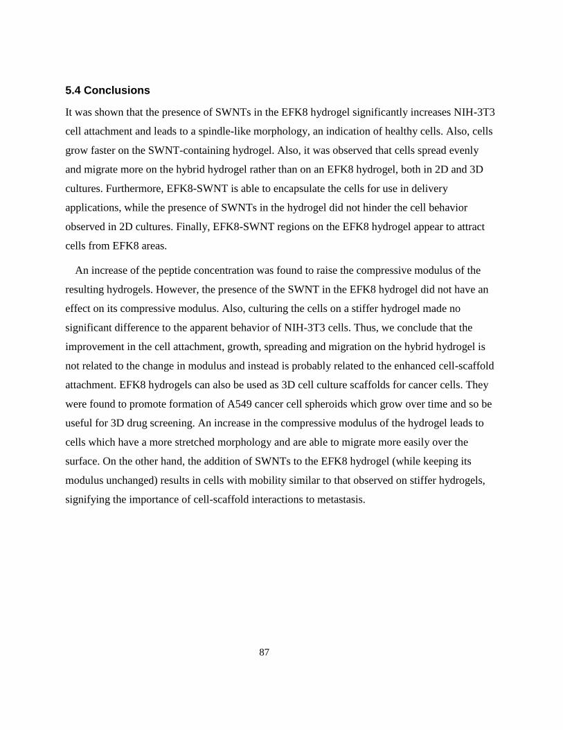
87
5.4 Conclusions
It was shown that the presence of SWNTs in the EFK8 hydrogel significantly increases NIH-3T3
cell attachment and leads to a spindle-like morphology, an indication of healthy cells. Also, cells
grow faster on the SWNT-containing hydrogel. Also, it was observed that cells spread evenly
and migrate more on the hybrid hydrogel rather than on an EFK8 hydrogel, both in 2D and 3D
cultures. Furthermore, EFK8-SWNT is able to encapsulate the cells for use in delivery
applications, while the presence of SWNTs in the hydrogel did not hinder the cell behavior
observed in 2D cultures. Finally, EFK8-SWNT regions on the EFK8 hydrogel appear to attract
cells from EFK8 areas.
An increase of the peptide concentration was found to raise the compressive modulus of the
resulting hydrogels. However, the presence of the SWNT in the EFK8 hydrogel did not have an
effect on its compressive modulus. Also, culturing the cells on a stiffer hydrogel made no
significant difference to the apparent behavior of NIH-3T3 cells. Thus, we conclude that the
improvement in the cell attachment, growth, spreading and migration on the hybrid hydrogel is
not related to the change in modulus and instead is probably related to the enhanced cell-scaffold
attachment. EFK8 hydrogels can also be used as 3D cell culture scaffolds for cancer cells. They
were found to promote formation of A549 cancer cell spheroids which grow over time and so be
useful for 3D drug screening. An increase in the compressive modulus of the hydrogel leads to
cells which have a more stretched morphology and are able to migrate more easily over the
surface. On the other hand, the addition of SWNTs to the EFK8 hydrogel (while keeping its
modulus unchanged) results in cells with mobility similar to that observed on stiffer hydrogels,
signifying the importance of cell-scaffold interactions to metastasis.
88
Chapter 6
Immobilization, Direct Electrochemistry and Electrocatalysis of
Hemoglobin on Peptide-Carbon Nanotube-Modified
Abstract
The direct electrochemistry of hemoglobin (Hb) immobilized on a glassy carbon electrode (GCE)
by mixing with a hybrid dispersion of EFK8 self-assembling peptide and single-walled carbon
nanotubes (SWNTs) was investigated and shown to have effective properties as a biosensor for
hydrogen peroxide (H2O2). Preliminary experiments involving cyclic voltammetry (CV) and
electrochemical impedance spectroscopy (EIS) showed that the presence of SWNTs in the
modifying peptide layer on GCE significantly enhanced the electrochemical response of the
electrode for the ferricyanide/ferrocyanide redox couple. Also, when more layers of the peptide-
SWNT dispersion were applied to the surface, the electrochemical response of the GCE was
further increased. This behavior was then exploited to fabricate a biosensor for H2O2 by mixing
hemoglobin with the hybrid peptide-SWNT dispersion and casting this mixture on a glassy
carbon electrode. Subsequent CV and EIS analysis revealed successful immobilization of Hb on
the electrode and the ability of the electrode to enable direct electron transfer from the Hb to the
electrode surface. In particular, CVs obtained in 0.1M PBS (pH 7.0) showed that the
immobilized Hb retained its bio-catalytic activity for Fe ions, indicating that it had not denatured
and the hybrid layer remained biocompatible with Hb. Furthermore, this electrode was found to
accurately measure the H2O2 concentration over the range from 20 to 9.6×10² μM in 0.1M PBS
(pH 7.0) under mediatorless conditions using both CV and amperometry techniques. In this way,
the EFK8-SWNT hybrid layer shows promise as a biocompatible layer for simple non-covalent
enzyme immobilization and the basis of a mediatorless biosensor.
89
6.1 Introduction
Since the 1970s, direct electron transfer between redox proteins and electrode surfaces and its
application for mediatorless electrochemical biosensors have been extensively studied. The most
efficient method to make a redox protein-based electrochemical biosensor is to establish direct
electron transfer between the protein and electrode. The use of a mediator facilitates not only the
electron transfer between the electrode and enzyme but also various interfering reactions.
Mediatorless biosensors can offer better selectivity since they are able to operate in a potential
range closer to the redox potential of the protein itself and thus make interfering reactions less
likely to occur 155156
. In addition, most in-vivo devices are mediatorless to prevent the potential
leaching and toxicity of the mediator. Mediated systems also tend to be less stable during
extended continuous operation 157
. Normally direct adsorption of proteins on the electrode
surface leads to their denaturation and loss of their catalytic and electrochemical activity 158
.
Thus, an important first step in designing a mediatorless biosensor is to immobilize the protein
without denaturation.
Hemoglobin (Hb) is an important protein in red blood cells as a reversible oxygen carrier in the
body through its four polypeptide chains which contain electroactive heme groups. It has been
reported that Hb also can catalyze the reduction of hydrogen peroxide 159
. The ability to rapidly
and accurately determine hydrogen peroxide concentration is very important since it is the
product of many enzymatic reactions and is also commonly found in food, clinical,
pharmaceutical, industrial and environmental systems 159–161156
. A number of techniques such as
HPLC 161
, titrimetry 162
, spectrometry 163
, chemiluminescence 164
and electrochemical methods
165 are currently available for hydrogen peroxide determination.
Electrochemical methods for hydrogen peroxide analysis have attracted extensive interest
because they are fast, less prone to interferences and relatively inexpensive 161
. Basically, two
types of amperometric enzyme-based H2O2 probes can be used − mediated biosensors and
mediatorless biosensors. Although the mediated H2O2 biosensors can detect very low
concentrations by use of electron transfer mediators such as ferrocene derivatives 166
,
hexacyanoferrates 167
, tetrathiafulvalene 168
or phenazine methosulphate 169
, the danger exists that
mediator molecules can contaminate the sample or electrode system or can diffuse out of the
90
enzyme layer 170
. Mediatorless biosensors which operate through the direct electron transfer
between redox proteins and electrode, have gained increasing attention because they do not
suffer from this leakage problem and have potentially simpler design without the need for a
chemical mediator.
In addition to its ability to electrocatalyze H2O2 reduction, Hb is an ideal model protein for the
study of the direct electron transfer of heme molecules due to its commercial availability,
reasonable cost and well-known structure. However, the direct electrochemical reaction of Hb on
an electrode is very difficult for a number of reasons. Since the heme group resides inside the Hb
structure and is surrounded by the protein polypeptide chains, the electrons being transferred
must travel a large distance to the electrode surface and a mediator is often required to help
transport them. Once adsorbed, Hb on the surface frequently denatures and loses its
electrochemical activity and bioactivity. Hb becomes a barrier to electron transfer on the
electrode surface once it becomes denatured 171
. Finally, Hb located at the electrode surface may
not have a favorable orientation for electron transfer. To date, different methods and
nanomaterials including Au, Pt and CdTe nanoparticles as well as graphene, CNTs and TiO2
nanorods have been employed to overcome the above obstacles and facilitate direct electron
transfer from Hb to the electrode 159,161,172–183
. These methods mainly operate by providing a
strong electronically conducting environment for Hb molecules on the surface. Although
promising results have been observed using these nanomaterials, the biosensor efficiency of Hb–
based H2O2 biosensors is still lower than other ones using different types of heme proteins such
as HRP and CAT 156
.
Recently, the potential of using ionic-complementary peptides in biocompatible electrodes to
immobilize glucose oxidase covalently and fabricate glucose biosensors was demonstrated 4849213
.
These peptides can self-assemble on surfaces as β-sheet layers that have considerable biological
and physiological stability 5450
and good in vitro and in vivo biocompatibility 55186
. This is crucial
for in vivo biosensors. However, at the same time, these results showed that the peptides on the
surface act as barriers to electron transfer from the enzyme to the electrode and thereby hinder
the electrode response and biosensor sensitivity. Previously, we have shown the ability of the
same self-assembling peptides to disperse multi-walled and single-walled carbon nanotubes in
91
water 191,209
. The surfaces modified with the peptide-CNT dispersions also have enough
biocompatibility for cell attachment and growth 191
. Consequently, we propose that the
combination of the peptides and carbon nanotubes in the form of a hybrid dispersion on the
surface should provide a biocompatible electrode for protein immobilization and in vivo
biosensing with an enhanced electrochemical response. This combination can provide a basis for
designing a mediatorless biosensor.
In the current study, we report a novel simple method to modify and increase the
electrochemical response of glassy carbon electrode using a self-assembling peptide-SWNT
coating. Then we show that this coating can adsorb Hb physically, remain biocompatible enough
for Hb to retain its redox activity and thereby enable direct electron transfer from the Hb to the
electrode and improve its catalytic activity toward H2O2 reduction.
6.2 Materials and Methods
6.2.1 Materials
The ionic complementary peptide EFK8 with a sequence of FEFEFKFK where F corresponds to
phenylalanine, E to glutamic acid and K to lysine was used in this study. This peptide was
synthesized in our laboratory using an Aapptec Apex 396 peptide synthesizer (Aapptec LLC,
USA). At neutral pH, F is a neutral hydrophobic residue, while E and K are negatively and
positively charged, respectively. The peptide was protected by acetyl and amino groups at the N
terminus and C-terminus, respectively, to prevent end-to-end electrostatic interactions between
peptides. EFK8 was dissolved in pure water (18.2 MΩ; Millipore Milli-Q system) at a
concentration of 0.5 mg/ml to prepare the peptide stock solution and then stored at 4°C before
use. The metallic SWNTs (carbon > 90%, carbon as SWNT > 77%) were purchased from
Sigma-Aldrich Co (catalog# 727777, lot# MKBH7136V). Hemoglobin (from bovine blood),
potassium ferrocyanide (K3Fe(CN)6) and H2O2 (30%) were obtained from Sigma-Aldrich.
Phosphate buffer saline (PBS) solution was made using Na2HPO4 and NaH2PO4 both at
analytical grade (EMD).
92
6.2.2 Methods
6.2.2.1 Peptide synthesis
All amino acids (Fmoc protected), activator 2-(6-chloro-1H-benzotriazole-1-yl)-1,1,3,3-
tetramethylaminium hexafluorophosphate (HCTU) and Rink Amide-AM resin were obtained
from Aapptec LLC (USA). All other solutions were purchased from Acros Organics (USA). The
EFK8 peptide with a molecular weight of 1162.60 g/mol was synthesized in our laboratory using
the solid-phase peptide synthesis (SPPS) method using an Aapptec Apex 396 peptide synthesizer
before being purified by repeated precipitation in cold ether. Then it was freeze-dried and the
final powder stored in a refrigerator. Matrix-assisted laser desorption ionization time-of-flight
mass spectroscopy (Q-TOF Ultima Global, Waters, Milford, MA, USA) was used to measure the
molar mass of the synthesized peptide.
6.2.2.2 SWNT dispersion preparation
The stock suspensions were prepared by combining EFK8 and as-received SWNT (carbon >
90%, carbon as SWNT > 77%) together at a 1:1 mass ratio in pure water (18.2 MΩ; Millipore
Milli-Q system) to yield concentrations of 2 mg/ml of both the peptide and SWNTs. The
concentration of 2 mg/ml SWNT is based on the mass of as-received material and so may include
components that are not actual SWNT. The suspensions were then mixed for 1 hour using a
Qsonica XL-2000 probe sonicator at a power of 10W and centrifuged at a speed of 2,000×g for
1h to produce a supernatant that was decanted for later use in electrode modification.
6.2.2.3 Electrochemical analysis
Electrochemical measurements were done using a VMP3 potentiostat/ galvanostat (Bio-Logic
instruments) using a three-electrode electrochemical cell at room temperature. Glassy carbon
electrode (GCE, diameter: 5mm) was used as the working electrode, platinum wire as the counter
and saturated calomel electrode (SCE) as the reference electrode. Electrolytes were deoxygenated
with pure nitrogen before each experiment. Cyclic voltammetry was done at a scan rate of 100
mV s−1
over the potential range from 0.6 V to −0.2 V in 10 mM K3Fe(CN)6 dissolved in 1M KCl
electrolyte, from 0.2 V to −0.8 V in 0.1 M PBS and from 0 V to −0.8 V in 0.1M PBS (pH 7.0).
93
Electrochemical impedance spectroscopy (EIS) was performed potentiostatically with 10 mV
amplitude sinusoidal waves superimposed on a constant potential of 0.29 V over a frequency
range of 1 mHz − 100 kHz in 10 mM K3Fe(CN)6 dissolved in 1M KCl electrolyte. Amperometric
experiments were done in 0.1M PBS (pH 7.0) containing different concentrations of hydrogen
peroxide.
6.2.2.4 Scanning electron microscopy
The coating was removed from the GCE surface and examined with SEM. The SEM images
were obtained using an FE-SEM (LEO 1530).
6.2.2.5 Electrode modification
Before modification, the electrode was polished successively with 1.0, 0.3 and 0.05 m alumina
slurry on a woolen cloth to obtain a mirror-like surface followed by bath sonication in ethanol
and water. Then the electrode was washed with acetone and air-dried. Electrode modification
was done by casting 35 l of the peptide or hybrid dispersion on the GCE surface and then left to
air-dry. For hemoglobin immobilization, Hb was dissolved in water and then mixed with an
EFK8-SWNT dispersion at a 1:1 (v/v) ratio. Then the mixture was casted on the GCE surface as
mentioned above and left overnight to dry at 4°C.
6.3 Results and Discussion
6.3.1 Electrode modification using EFK8 and EFK8-SWNT hybrid dispersion
As the first step, we investigate the effects of the following two modifications of the GCE – first
with a coating formed from an EFK8 peptide solution and the second with an EFK8-SWNT
dispersion coating. Cyclic voltammetry was conducted on these modified electrodes in a 1M KCl
solution containing 10 mM K3Fe(CN)6. The resulting current associated with the
[Fe(CN)6]3−
/[Fe(CN)6]4−
couple is used as a measure of the electrochemical response of the
electrodes. A comparison of the scans obtained on the bare GCE and EFK8-modified GCE shows
that the presence of the peptide alone on the surface diminishes the cathodic and anodic peak
currents associated with the Fe(CN)63−
/Fe(CN)64−
couple (Figure 6.1). This is presumably due to
the peptide layer blocking the electron transfer pathway from the solution to the electrode. On the
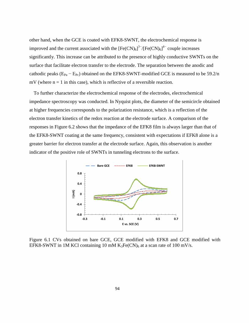
94
other hand, when the GCE is coated with EFK8-SWNT, the electrochemical response is
improved and the current associated with the [Fe(CN)6]3−
/[Fe(CN)6]4−
couple increases
significantly. This increase can be attributed to the presence of highly conductive SWNTs on the
surface that facilitate electron transfer to the electrode. The separation between the anodic and
cathodic peaks (EPa − EPc) obtained on the EFK8-SWNT-modified GCE is measured to be 59.2/n
mV (where n = 1 in this case), which is reflective of a reversible reaction.
To further characterize the electrochemical response of the electrodes, electrochemical
impedance spectroscopy was conducted. In Nyquist plots, the diameter of the semicircle obtained
at higher frequencies corresponds to the polarization resistance, which is a reflection of the
electron transfer kinetics of the redox reaction at the electrode surface. A comparison of the
responses in Figure 6.2 shows that the impedance of the EFK8 film is always larger than that of
the EFK8-SWNT coating at the same frequency, consistent with expectations if EFK8 alone is a
greater barrier for electron transfer at the electrode surface. Again, this observation is another
indicator of the positive role of SWNTs in tunneling electrons to the surface.
Figure 6.1 CVs obtained on bare GCE, GCE modified with EFK8 and GCE modified with
EFK8-SWNT in 1M KCl containing 10 mM K3Fe(CN)6 at a scan rate of 100 mV/s.
-0.8
-0.4
0
0.4
0.8
-0.3 -0.1 0.1 0.3 0.5 0.7
I (m
A)
E vs. SCE (V)
Bare GCE EFK8 EFK8-SWNT
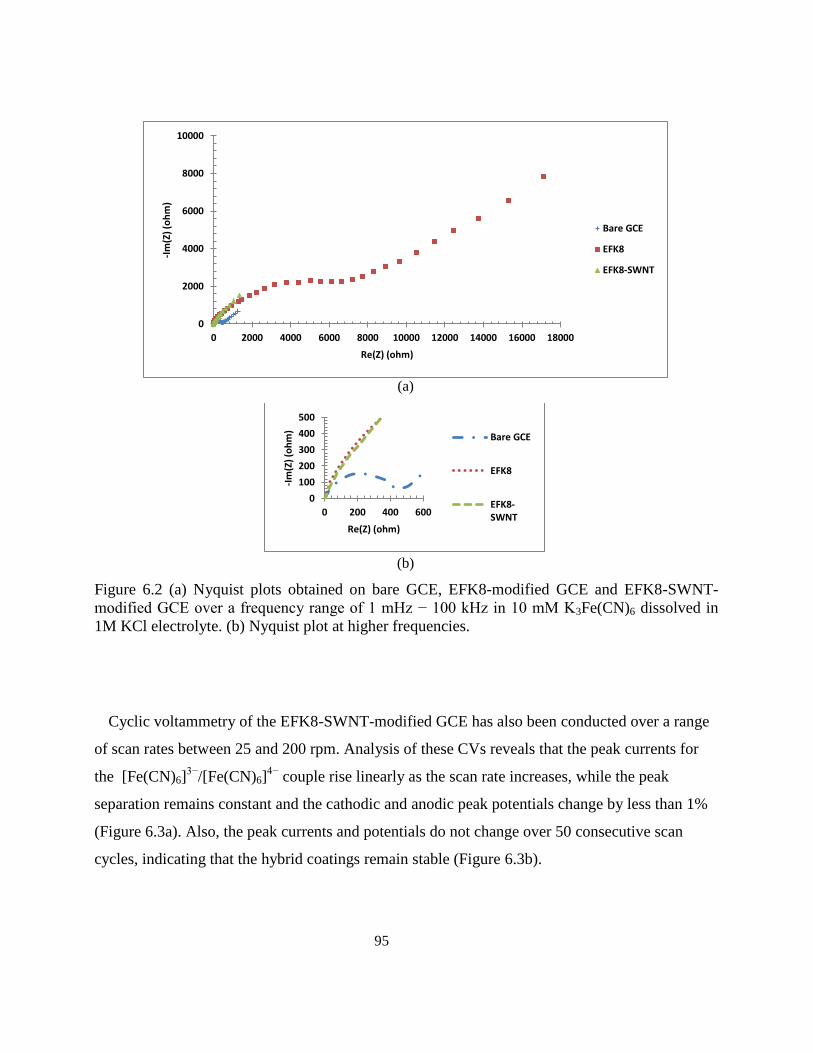
95
(a)
(b)
Figure 6.2 (a) Nyquist plots obtained on bare GCE, EFK8-modified GCE and EFK8-SWNT-
modified GCE over a frequency range of 1 mHz − 100 kHz in 10 mM K3Fe(CN)6 dissolved in
1M KCl electrolyte. (b) Nyquist plot at higher frequencies.
Cyclic voltammetry of the EFK8-SWNT-modified GCE has also been conducted over a range
of scan rates between 25 and 200 rpm. Analysis of these CVs reveals that the peak currents for
the [Fe(CN)6]3−
/[Fe(CN)6]4−
couple rise linearly as the scan rate increases, while the peak
separation remains constant and the cathodic and anodic peak potentials change by less than 1%
(Figure 6.3a). Also, the peak currents and potentials do not change over 50 consecutive scan
cycles, indicating that the hybrid coatings remain stable (Figure 6.3b).
0
2000
4000
6000
8000
10000
0 2000 4000 6000 8000 10000 12000 14000 16000 18000
-Im
(Z)
(oh
m)
Re(Z) (ohm)
Bare GCE
EFK8
EFK8-SWNT
0
100
200
300
400
500
0 200 400 600
-Im
(Z)
(oh
m)
Re(Z) (ohm)
Bare GCE
EFK8
EFK8-SWNT
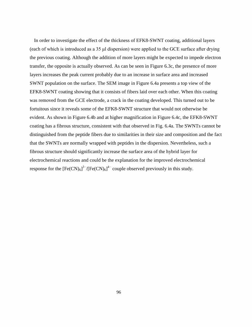
96
In order to investigate the effect of the thickness of EFK8-SWNT coating, additional layers
(each of which is introduced as a 35 μl dispersion) were applied to the GCE surface after drying
the previous coating. Although the addition of more layers might be expected to impede electron
transfer, the opposite is actually observed. As can be seen in Figure 6.3c, the presence of more
layers increases the peak current probably due to an increase in surface area and increased
SWNT population on the surface. The SEM image in Figure 6.4a presents a top view of the
EFK8-SWNT coating showing that it consists of fibers laid over each other. When this coating
was removed from the GCE electrode, a crack in the coating developed. This turned out to be
fortuitous since it reveals some of the EFK8-SWNT structure that would not otherwise be
evident. As shown in Figure 6.4b and at higher magnification in Figure 6.4c, the EFK8-SWNT
coating has a fibrous structure, consistent with that observed in Fig. 6.4a. The SWNTs cannot be
distinguished from the peptide fibers due to similarities in their size and composition and the fact
that the SWNTs are normally wrapped with peptides in the dispersion. Nevertheless, such a
fibrous structure should significantly increase the surface area of the hybrid layer for
electrochemical reactions and could be the explanation for the improved electrochemical
response for the [Fe(CN)6]3−
/[Fe(CN)6]4−
couple observed previously in this study.

97
(a)
(b)
(c)
Figure 6.3 (a) Effect of scan rate on the cathodic and anodic peak currents of
Fe(CN)63−
/Fe(CN)64−
couple on an EFK8-SWNT modified electrode. (b) Traces of the CV
responses over 50 cycles. (c) Effect of the number of EFK8-SWNT hybrid layers on the CVs
obtained at a scan rate of 100 mV/s in 1M KCl containing 10 mM K3Fe(CN)6.
-1.5
-1
-0.5
0
0.5
1
1.5
0 50 100 150 200 250
Pe
ak c
urr
en
t (m
A)
Scan rate (mV/s)
Cathodic Anodic
-0.8
-0.4
0
0.4
0.8
-0.3 -0.1 0.1 0.3 0.5 0.7
I (m
A)
E vs. SCE (V)
-1.5
-1
-0.5
0
0.5
1
1.5
-0.3 -0.1 0.1 0.3 0.5 0.7
I (m
A)
E vs. SCE (V)
1 layer 2 layers 3 layers
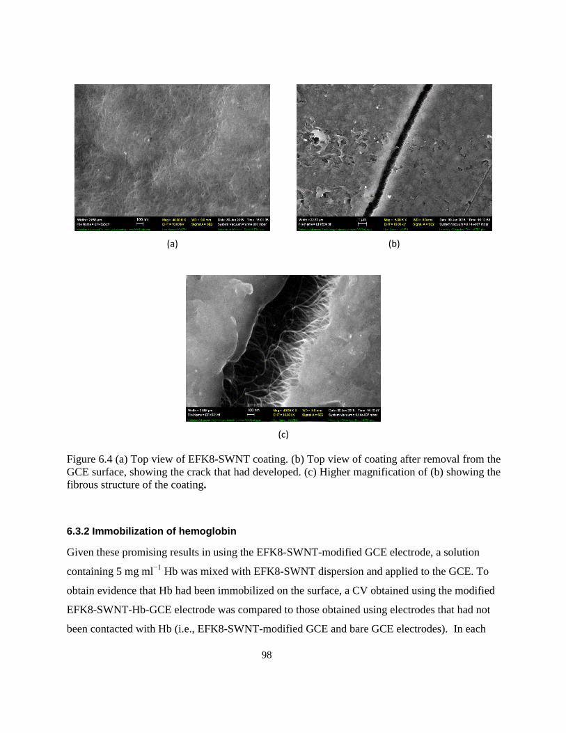
98
(a)
(b)
(c)
Figure 6.4 (a) Top view of EFK8-SWNT coating. (b) Top view of coating after removal from the
GCE surface, showing the crack that had developed. (c) Higher magnification of (b) showing the
fibrous structure of the coating.
6.3.2 Immobilization of hemoglobin
Given these promising results in using the EFK8-SWNT-modified GCE electrode, a solution
containing 5 mg ml−1
Hb was mixed with EFK8-SWNT dispersion and applied to the GCE. To
obtain evidence that Hb had been immobilized on the surface, a CV obtained using the modified
EFK8-SWNT-Hb-GCE electrode was compared to those obtained using electrodes that had not
been contacted with Hb (i.e., EFK8-SWNT-modified GCE and bare GCE electrodes). In each
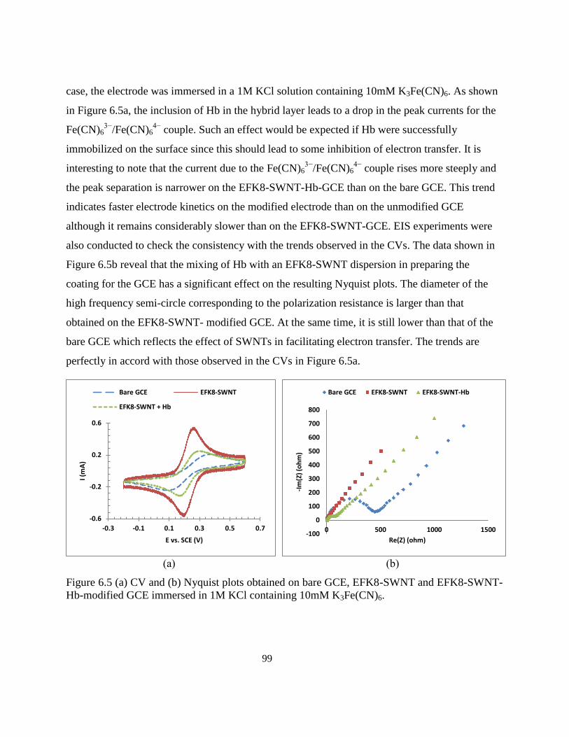
99
case, the electrode was immersed in a 1M KCl solution containing 10mM K3Fe(CN)6. As shown
in Figure 6.5a, the inclusion of Hb in the hybrid layer leads to a drop in the peak currents for the
Fe(CN)63−
/Fe(CN)64−
couple. Such an effect would be expected if Hb were successfully
immobilized on the surface since this should lead to some inhibition of electron transfer. It is
interesting to note that the current due to the Fe(CN)63−
/Fe(CN)64−
couple rises more steeply and
the peak separation is narrower on the EFK8-SWNT-Hb-GCE than on the bare GCE. This trend
indicates faster electrode kinetics on the modified electrode than on the unmodified GCE
although it remains considerably slower than on the EFK8-SWNT-GCE. EIS experiments were
also conducted to check the consistency with the trends observed in the CVs. The data shown in
Figure 6.5b reveal that the mixing of Hb with an EFK8-SWNT dispersion in preparing the
coating for the GCE has a significant effect on the resulting Nyquist plots. The diameter of the
high frequency semi-circle corresponding to the polarization resistance is larger than that
obtained on the EFK8-SWNT- modified GCE. At the same time, it is still lower than that of the
bare GCE which reflects the effect of SWNTs in facilitating electron transfer. The trends are
perfectly in accord with those observed in the CVs in Figure 6.5a.
(a)
(b)
Figure 6.5 (a) CV and (b) Nyquist plots obtained on bare GCE, EFK8-SWNT and EFK8-SWNT-
Hb-modified GCE immersed in 1M KCl containing 10mM K3Fe(CN)6.
-0.6
-0.2
0.2
0.6
-0.3 -0.1 0.1 0.3 0.5 0.7
I (m
A)
E vs. SCE (V)
Bare GCE EFK8-SWNT
EFK8-SWNT + Hb
-100
0
100
200
300
400
500
600
700
800
0 500 1000 1500
-Im
(Z)
(oh
m)
Re(Z) (ohm)
Bare GCE EFK8-SWNT EFK8-SWNT-Hb
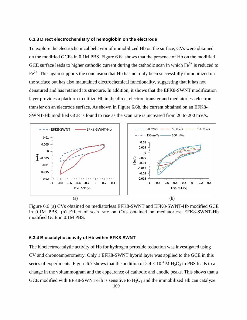
100
6.3.3 Direct electrochemistry of hemoglobin on the electrode
To explore the electrochemical behavior of immobilized Hb on the surface, CVs were obtained
on the modified GCEs in 0.1M PBS. Figure 6.6a shows that the presence of Hb on the modified
GCE surface leads to higher cathodic current during the cathodic scan in which Fe3+
is reduced to
Fe2+
. This again supports the conclusion that Hb has not only been successfully immobilized on
the surface but has also maintained electrochemical functionality, suggesting that it has not
denatured and has retained its structure. In addition, it shows that the EFK8-SWNT modification
layer provides a platform to utilize Hb in the direct electron transfer and mediatorless electron
transfer on an electrode surface. As shown in Figure 6.6b, the current obtained on an EFK8-
SWNT-Hb modified GCE is found to rise as the scan rate is increased from 20 to 200 mV/s.
(a)
(b)
Figure 6.6 (a) CVs obtained on mediatorless EFK8-SWNT and EFK8-SWNT-Hb modified GCE
in 0.1M PBS. (b) Effect of scan rate on CVs obtained on mediatorless EFK8-SWNT-Hb
modified GCE in 0.1M PBS.
6.3.4 Biocatalytic activity of Hb within EFK8-SWNT
The bioelectrocatalytic activity of Hb for hydrogen peroxide reduction was investigated using
CV and chronoamperometry. Only 1 EFK8-SWNT hybrid layer was applied to the GCE in this
series of experiments. Figure 6.7 shows that the addition of 2.4 × 10⁻⁴
M H2O2 to PBS leads to a
change in the voltammogram and the appearance of cathodic and anodic peaks. This shows that a
GCE modified with EFK8-SWNT-Hb is sensitive to H2O2 and the immobilized Hb can catalyze
-0.02
-0.015
-0.01
-0.005
0
0.005
0.01
-1 -0.8 -0.6 -0.4 -0.2 0 0.2 0.4
I (m
A)
E vs. SCE (V)
EFK8-SWNT EFK8-SWNT-Hb
-0.025
-0.02
-0.015
-0.01
-0.005
0
0.005
0.01
-1 -0.8 -0.6 -0.4 -0.2 0 0.2 0.4
I (m
A)
E vs. SCE (V)
20 mV/s 50 mV/s 100 mV/s
150 mV/s 200 mV/s
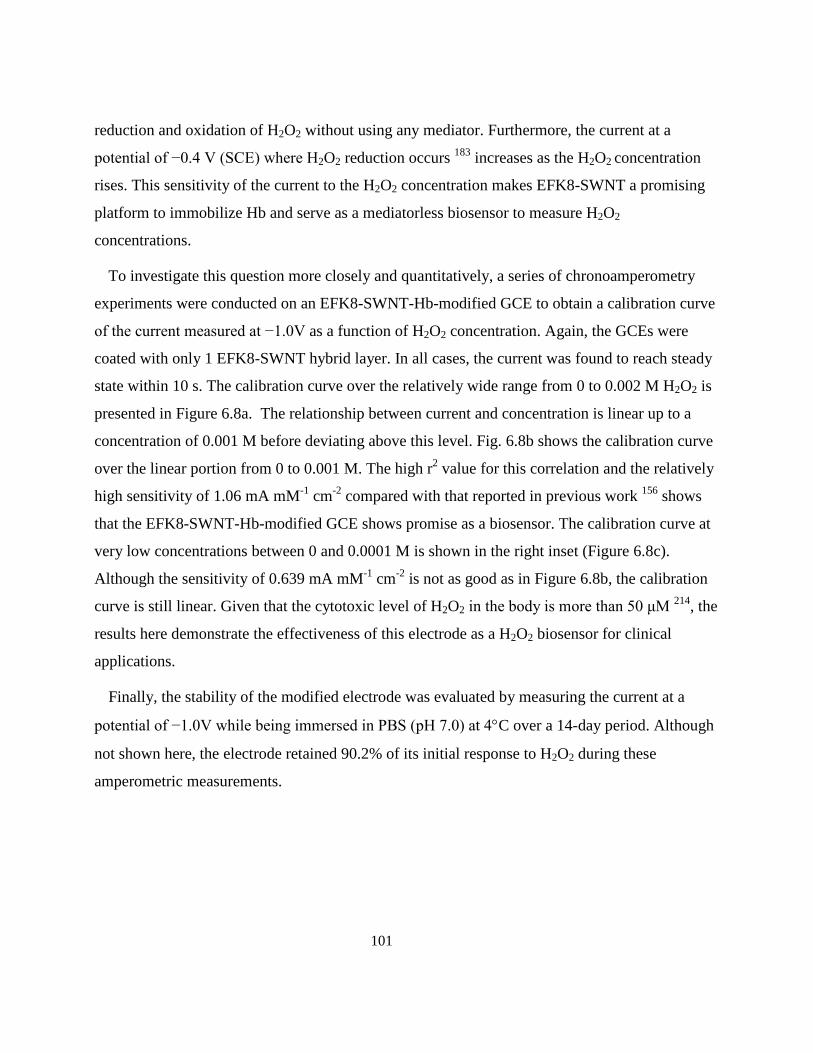
101
reduction and oxidation of H2O2 without using any mediator. Furthermore, the current at a
potential of −0.4 V (SCE) where H2O2 reduction occurs 183
increases as the H2O2 concentration
rises. This sensitivity of the current to the H2O2 concentration makes EFK8-SWNT a promising
platform to immobilize Hb and serve as a mediatorless biosensor to measure H2O2
concentrations.
To investigate this question more closely and quantitatively, a series of chronoamperometry
experiments were conducted on an EFK8-SWNT-Hb-modified GCE to obtain a calibration curve
of the current measured at −1.0V as a function of H2O2 concentration. Again, the GCEs were
coated with only 1 EFK8-SWNT hybrid layer. In all cases, the current was found to reach steady
state within 10 s. The calibration curve over the relatively wide range from 0 to 0.002 M H2O2 is
presented in Figure 6.8a. The relationship between current and concentration is linear up to a
concentration of 0.001 M before deviating above this level. Fig. 6.8b shows the calibration curve
over the linear portion from 0 to 0.001 M. The high r2 value for this correlation and the relatively
high sensitivity of 1.06 mA mM-1
cm-2
compared with that reported in previous work 156
shows
that the EFK8-SWNT-Hb-modified GCE shows promise as a biosensor. The calibration curve at
very low concentrations between 0 and 0.0001 M is shown in the right inset (Figure 6.8c).
Although the sensitivity of 0.639 mA mM-1
cm-2
is not as good as in Figure 6.8b, the calibration
curve is still linear. Given that the cytotoxic level of H2O2 in the body is more than 50 μM 214
, the
results here demonstrate the effectiveness of this electrode as a H2O2 biosensor for clinical
applications.
Finally, the stability of the modified electrode was evaluated by measuring the current at a
potential of −1.0V while being immersed in PBS (pH 7.0) at 4C over a 14-day period. Although
not shown here, the electrode retained 90.2% of its initial response to H2O2 during these
amperometric measurements.
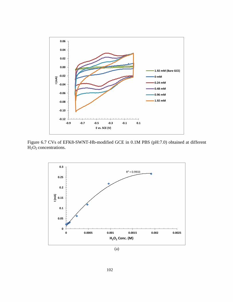
102
Figure 6.7 CVs of EFK8-SWNT-Hb-modified GCE in 0.1M PBS (pH:7.0) obtained at different
H2O2 concentrations.
(a)
-0.12
-0.10
-0.08
-0.06
-0.04
-0.02
0.00
0.02
0.04
0.06
-0.9 -0.7 -0.5 -0.3 -0.1 0.1
I (m
A)
E vs. SCE (V)
1.92 mM (Bare GCE)
0 mM
0.24 mM
0.48 mM
0.96 mM
1.92 mM
R² = 0.9933
0
0.05
0.1
0.15
0.2
0.25
0.3
0 0.0005 0.001 0.0015 0.002 0.0025
I (m
A)
H2O2 Conc. (M)
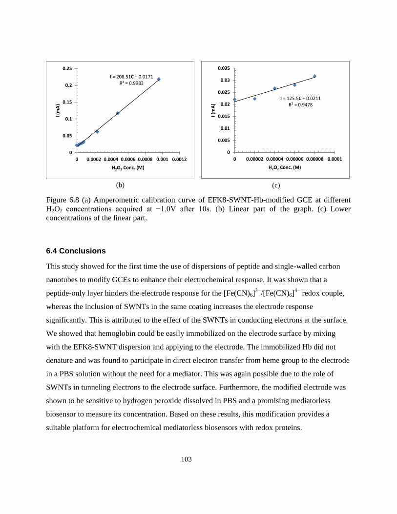
103
(b)
(c)
Figure 6.8 (a) Amperometric calibration curve of EFK8-SWNT-Hb-modified GCE at different
H2O2 concentrations acquired at −1.0V after 10s. (b) Linear part of the graph. (c) Lower
concentrations of the linear part.
6.4 Conclusions
This study showed for the first time the use of dispersions of peptide and single-walled carbon
nanotubes to modify GCEs to enhance their electrochemical response. It was shown that a
peptide-only layer hinders the electrode response for the [Fe(CN)6]3−
/[Fe(CN)6]4−
redox couple,
whereas the inclusion of SWNTs in the same coating increases the electrode response
significantly. This is attributed to the effect of the SWNTs in conducting electrons at the surface.
We showed that hemoglobin could be easily immobilized on the electrode surface by mixing
with the EFK8-SWNT dispersion and applying to the electrode. The immobilized Hb did not
denature and was found to participate in direct electron transfer from heme group to the electrode
in a PBS solution without the need for a mediator. This was again possible due to the role of
SWNTs in tunneling electrons to the electrode surface. Furthermore, the modified electrode was
shown to be sensitive to hydrogen peroxide dissolved in PBS and a promising mediatorless
biosensor to measure its concentration. Based on these results, this modification provides a
suitable platform for electrochemical mediatorless biosensors with redox proteins.
I = 208.51C + 0.0171 R² = 0.9983
0
0.05
0.1
0.15
0.2
0.25
0 0.0002 0.0004 0.0006 0.0008 0.001 0.0012
I (m
A)
H2O2 Conc. (M)
I = 125.5C + 0.0211 R² = 0.9478
0
0.005
0.01
0.015
0.02
0.025
0.03
0.035
0 0.00002 0.00004 0.00006 0.00008 0.0001
I (m
A)
H2O2 Conc. (M)
104
Chapter 7
Conclusions and Recommendations
7.1 Original contributions to research
Due to problems such as reduced performance and biocompatibility of CNTs after dispersing via
covalent modification or the addition of most surfactants, the use of biocompatible nanomaterials
for this purpose is of great interest. Therefore, the possibility of dispersing CNTs using a
particular sequence of self-assembling peptide has been investigated in this study. This thesis
focuses on hybrid dispersions of ionic-complementary self-assembling peptides and carbon
nanotubes, investigates the interaction between these peptides and CNTs, uses these hybrid
dispersions to form a composite hydrogel and exploits their properties for tissue engineering and
biosensor applications. In the following, the most important outcomes of this research are
summarized:
Dispersion of MWNTs using EFK16-II peptide
EFK16-II appears to self-assemble on the sidewalls of MWNTs and disperse them in water
through a non-covalent functionalizing mechanism involving hydrophobic and π-π interactions.
The stability of suspensions containing EFK16-II-modified MWNTs in water depends very
strongly on pH. They remain stable for long periods of time at pH below about 5 and above about
8 where the modified particles are highly charged. On the other hand, at pHs close to the
isoelectric point of EFK16-II (pH ~6.7), MWNTs agglomerate and their suspensions become
unstable. Furthermore, experiments using tissue culture plates modified with EFK16-II-modified
MWNTs show that they provide a biocompatible surface for attachment and growth of normal
and cancer cells.
Dispersion of SWNTs using EFK8 peptide and formation of hybrid hydrogel
By applying scanning probe microscopy (SPM), this study provides new evidence that the EFK8
peptide can wrap around the nanotubes, thereby rendering them hydrophilic and enabling their
105
dispersion in aqueous media. For the first time, nano-mechanical measurements as well as
electric force microscopy (EFM) technique have been successfully used to distinguish peptide
fibers from SWNTs on the surface, something which was not possible using regular AFM
imaging. Also, by adding salt to EFK8-SWNT dispersions, we have shown that dispersed
SWNTs remain entrapped and incorporated in hybrid EFK8-SWNT hydrogels that form.
Application of hybrid EFK8-SWNT hydrogel for tissue engineering and 3D cancer
spheroid formation
It has been shown that the presence of SWNTs in the EFK8 hydrogel promotes NIH-3T3 cell
attachment and leads to a spindle-like morphology, an indication of healthy cells. Also, cells
grow faster on the SWNT-containing hydrogel. Also, cells are observed to spread evenly and
migrate more rapidly on the hybrid hydrogel than on an EFK8 hydrogel in both 2D and 3D
cultures. Furthermore, EFK8-SWNT is able to encapsulate the cells for use in delivery
applications, while the presence of SWNTs in the hydrogel did not hinder the cell behavior
observed in 2D cultures. Microindentation tests reveal that the compressive modulus of the
resulting hydrogels is increased by raising the peptide concentration. On the other hand, the
presence of the SWNT in the EFK8 hydrogel does not alter its compressive modulus. Also,
culturing NIH-3T3 cells on a stiffer hydrogel has no significant apparent effect on their
subsequent behavior. This implies that the improvement in the cell attachment, growth, spreading
and migration on the hybrid hydrogel are not strongly related to the change in stiffness and
instead is probably related to the enhanced cell-scaffold attachment. EFK8 hydrogels have also
been used as 3D cell culture scaffolds for cancer cells and found to promote spheroid formation
of A549 cancer cell colonies which grow by time. This effect makes these hydrogels useful for
3D drug screening. An increase in the compressive modulus of the hydrogel leads to cells with a
more stretched morphology and more able to migrate over the surface. On the other hand, the
addition of SWNTs to the EFK8 hydrogel (while keeping its modulus unchanged) results in cells
with mobility similar to that observed on stiffer hydrogels, signifying the importance of cell-
scaffold interactions for metastasis.
106
Application of hybrid EFK8-SWNT dispersion for Hb immobilization, direct
electrochemistry and H2O2 sensing
This study shows for the first time the use of dispersions of peptide and single-walled carbon
nanotubes to modify GCEs to enhance their electrochemical response. It has been shown that a
peptide-only layer hinders the electrode response for the [Fe(CN)6]3−
/[Fe(CN)6]4−
redox couple,
whereas the inclusion of SWNTs in the same coating increases the electrode response
significantly. This is attributed to the effect of the SWNTs in conducting electrons at the surface.
We showed that hemoglobin can be easily immobilized on the electrode surface by mixing with
the EFK8-SWNT dispersion and applying onto the electrode. The immobilized Hb does not
denature and is found to participate in direct electron transfer between its heme group and the
electrode in a PBS solution without the need for a mediator. This behavior is again possible due
to the role that SWNTs play in tunneling electrons to the electrode surface. Furthermore, the
modified electrode is sensitive enough to hydrogen peroxide dissolved in PBS in order for it to
be a promising mediatorless biosensor to measure its concentration. Based on these results, this
modification provides a suitable platform for electrochemical mediatorless biosensors with redox
proteins.
7.2 Recommendations
Based on the thesis outcomes, future research on the following topics is recommended:
1. Application of new SPM techniques (i.e. nano-mechanical measurements and EFM) to
more closely investigate peptide-MWNT interactions
2. Dispersion of semiconducting SWNTs using peptides to benefit from the fluorescing
properties of this type of SWNT as a tool to gain greater insight into this interaction
3. Introduction of an RGD motif into the EFK8 peptide sequence to further enhance cell
attachment
4. Improvement of the EFK8 sequence in order to load more SWNT and better manipulate
hydrogel electrical and mechanical properties

107
5. Investigation of the mechanism of cell attachment to the EFK8-SWNT hydrogel to gain a
better understanding of the role that SWNTs play
6. Use of several layers of the EFK8-SWNT dispersion for Hb immobilization and
investigation of its effect on the sensitivity of the resulting H2O2 biosensor
108
Bibliography
1. Wagner, V., Dullaart, A., Bock, A. & Zweck, A. The emerging nanomedicine landscape. Nat.
Biotechnol. 24, 1211–1217 (2006).
2. Freitas, R. A. What is nanomedicine? Nanomedicine 1, 2–9 (2005).
3. Sapsford, K. E. et al. Functionalizing Nanoparticles with Biological Molecules: Developing
Chemistries that Facilitate Nanotechnology. Chem. Rev. 113, 1904–2074 (2013).
4. Ijima, S. Helical microtubules of graphitic carbon. Nature 354, 56–58 (1991).
5. De Volder, M. F. L., Tawfick, S. H., Baughman, R. H. & Hart, A. J. Carbon Nanotubes:
Present and Future Commercial Applications. Science (80-. ). 339, 535–539 (2013).
6. Yu, M. et al. Strength and Breaking Mechanism of Multiwalled Carbon Nanotubes Under
Tensile Load. Science (80-. ). 287, 637–641 (2000).
7. Popov, M., Kyotani, M., Nemanich, R. & Koga, Y. Superhard phase composed of single-wall
carbon nanotubes. Phys. Rev. B 65, 033408 (2002).
8. Hong, S. & Myung, S. Nanotube Electronics: A flexible approach to mobility. Nat.
Nanotechnol. 2, 207 – 208 (2007).
9. Pop, E., Mann, D., Wang, Q., Goodson, K. & Dai, H. Thermal Conductance of an Individual
Single-Wall Carbon Nanotube above Room Temperature. Nano Lett. 6, 96–100 (2006).
10. Carbon Nanotubes and Related Structures Synthesis, Characterization, Functionalization, and
Applications. 103–198 (WILEY-VCH Verlag GmbH & Co, 2010).
11. Feng, M., Hanb, H., Zhang, J. & Tachikawa, H. in Electrochem. Sensors, Biosens. their
Biomed. Appl. (Zhang, X., Ju, H. & Wang, J.) 459–501 (Elsevier Inc., 2008).
12. Pantarotto, D. et al. Synthesis , Structural Characterization , and Immunological Properties of
Carbon Nanotubes Functionalized with Peptides. J. Am. Chem. Soc 125, 6160–6164 (2003).
13. Wang, S. et al. Peptides with selective affinity for carbon nanotubes. Nat. Mater. 2, 196–200
(2003).
14. Su, Z., Mui, K., Daub, E., Leung, T. & Honek, J. Single-walled carbon nanotube binding
peptides: probing tryptophan’s importance by unnatural amino acid substitution. J. Phys.
Chem. B 111, 14411–7 (2007).
15. Dieckmann, G. R. et al. Controlled assembly of carbon nanotubes by designed amphiphilic
Peptide helices. J. Am. Chem. Soc. 125, 1770–7 (2003).
109
16. Zorbas, V. et al. Preparation and characterization of individual peptide-wrapped single-walled
carbon nanotubes. J. Am. Chem. Soc. 126, 7222–7 (2004).
17. Arnold, M. S., Guler, M. O., Hersam, M. C. & Stupp, S. I. Encapsulation of carbon nanotubes
by self-assembling peptide amphiphiles. Langmuir 21, 4705–9 (2005).
18. Lim, Y., Moon, K.-S. & Lee, M. Recent advances in functional supramolecular nanostructures
assembled from bioactive building blocks. Chem. Soc. Rev. 38, 925–34 (2009).
19. Yanlian, Y. et al. Designer self-assembling peptide nanomaterials. Nano Today 4, 193–210
(2009).
20. Loo, Y., Zhang, S. & Hauser, C. A. E. From short peptides to nanofibers to macromolecular
assemblies in biomedicine. Biotechnol. Adv. 30, 593–603 (2012).
21. Yang, Z. & Zhao, X. A 3D model of ovarian cancer cell lines on peptide nanofiber scaffold to
explore the cell-scaffold interaction and chemotherapeutic resistance of anticancer drugs. Int.
J. Nanomedicine 6, 303–10 (2011).
22. Fung, S. Y. et al. Self-Assembling Peptide as a Potential Carrier for Hydrophobic Anticancer
Drug Ellipticine: Complexation, Release and In Vitro Delivery. Adv. Funct. Mater. 19, 74–83
(2009).
23. Wu, E. C., Zhang, S. & Hauser, C. A. E. Self-Assembling Peptides as Cell-Interactive
Scaffolds. Adv. Funct. Mater. 22, 456–468 (2012).
24. Lakshmanan, A., Zhang, S. & Hauser, C. A. E. Short self-assembling peptides as building
blocks for modern nanodevices. Trends Biotechnol. 30, 155–65 (2012).
25. Wang, J. Carbon-Nanotube Based Electrochemical Biosensors: A Review. Electroanalysis 17,
7–14 (2005).
26. Rivas, G. A. et al. Carbon nanotubes for electrochemical biosensing. Talanta 74, 291–307
(2007).
27. Harrison, B. S. & Atala, A. Carbon nanotube applications for tissue engineering. Biomaterials
28, 344–53 (2007).
28. Voge, C. M. & Stegemann, J. P. Carbon nanotubes in neural interfacing applications. J.
Neural Eng. 8, 011001 (2011).
29. Li, J., Cassell, A., Delzeit, L., Han, J. & Meyyappan, M. Novel Three-Dimensional
Electrodes: Electrochemical Properties of Carbon Nanotube Ensembles. J. Phys. Chem. B 106,
9299–9305 (2002).
110
30. Britto, P. J., Santhanam, K. S. V., Rubio, A., Alonso, J. a. & Ajayan, P. M. Improved Charge
Transfer at Carbon Nanotube Electrodes. Adv. Mater. 11, 154–157 (1999).
31. Kang, Y. & Taton, T. A. Micelle-encapsulated carbon nanotubes: a route to nanotube
composites. J. Am. Chem. Soc. 125, 5650–1 (2003).
32. Shi, J. et al. Actuator based on MWNT/PVA hydrogels. J. Phys. Chem. B 109, 14789–91
(2005).
33. Ogoshi, T., Takashima, Y., Yamaguchi, H. & Harada, A. Chemically-responsive sol-gel
transition of supramolecular single-walled carbon nanotubes (SWNTs) hydrogel made by
hybrids of SWNTs and cyclodextrins. J. Am. Chem. Soc. 129, 4878–9 (2007).
34. Tong, X., Zheng, J., Lu, Y., Zhang, Z. & Cheng, H. Swelling and mechanical behaviors of
carbon nanotube/poly(vinyl alcohol) hybrid hydrogels. Mater. Lett. 61, 1704–1706 (2007).
35. Thompson, B. C. et al. Carbon nanotube biogels. Carbon N. Y. 47, 1282–1291 (2009).
36. Gavalas, V. G., Andrews, R., Bhattacharyya, D. & Bachas, L. G. Carbon Nanotube Sol−Gel
Composite Materials. Nano Lett. 1, 719–721 (2001).
37. Yildirim, E. D., Yin, X., Nair, K. & Sun, W. Fabrication, characterization, and
biocompatibility of single-walled carbon nanotube-reinforced alginate composite scaffolds
manufactured using freeform fabrication technique. J. Biomed. Mater. Res. B. Appl. Biomater.
87, 406–14 (2008).
38. Abarrategi, A. et al. Multiwall carbon nanotube scaffolds for tissue engineering purposes.
Biomaterials 29, 94–102 (2008).
39. Firkowska, I. Carbon Nanotube Substrates for Tissue Engineering Applications. (2008).
40. Lewitus, D. Y. et al. Biohybrid Carbon Nanotube/Agarose Fibers for Neural Tissue
Engineering. Adv. Funct. Mater. 21, 2624–2632 (2011).
41. Haniu, H. et al. Basic Potential of Carbon Nanotubes in Tissue Engineering Applications. J.
Nanomater. 2012, 1–10 (2012).
42. Yang, S. & Zang, R. Perspectives on Carbon Nanotube-Based Scaffolds in Nerve Tissue
Engineering. J. Tissue. Sci. Eng. 3, 1–2 (2012).
43. Zhang, M. et al. Electrostatic layer-by-layer assembled carbon nanotube multilayer film and
its electrocatalytic activity for O2 reduction. Langmuir 20, 8781–5 (2004).
44. Moore, V. C. et al. Individually Suspended Single-Walled Carbon Nanotubes in Various
Surfactants. Nano Lett. 3, 1379–1382 (2003).
111
45. Zhang, S. Emerging biological materials through molecular. Biotechnol. Adv. 20, 321–339
(2002).
46. Ellis-Behnke, R. G. et al. Nano hemostat solution: immediate hemostasis at the nanoscale.
Nanomedicine 2, 207–15 (2006).
47. Fung, S.-Y. et al. Amino Acid Pairing for De Novo Design of Self-Assembling Peptides and
Their Drug Delivery Potential. Adv. Funct. Mater. 21, 2456–2464 (2011).
48. Yang, H. et al. Ionic-Complementary Peptide-Modified Highly Ordered Pyrolytic Graphite
Electrode for Biosensor Application. Biotechnol. Prog. 24, 964–971 (2008).
49. Yang, H., Fung, S.-Y., Pritzker, M. & Chen, P. Ionic-complementary peptide matrix for
enzyme immobilization and biomolecular sensing. Langmuir 25, 7773–7 (2009).
50. Zhang, S., Holmes, T., Lockshin, C. & Rich, A. Spontaneous assembly of a self-
complementary oligopeptide to form a stable macroscopic membrane. Proc. Natl. Acad. Sci.
U. S. A. 90, 3334–8 (1993).
51. Zhang, S. et al. Self-complementary oligopeptide matrices support mammalian cell
attachment. Biomaterials 16, 1385–93 (1995).
52. Mujeeb, A., Miller, A. F., Saiani, A. & Gough, J. E. Self-assembled octapeptide scaffolds for
in vitro chondrocyte culture. Acta Biomater. 9, 4609–17 (2013).
53. Fung, S. Y., Keyes, C., Duhamel, J. & Chen, P. Concentration effect on the aggregation of a
self-assembling oligopeptide. Biophys. J. 85, 537–48 (2003).
54. Zhang, S., Lockshin, C., Cook, R. & Rich, A. Unusually Stable β-Sheet Formation in an Ionic
Self-Complementary Oligopeptide Stability of the Structure in Dilute Solution. Biopolymers
34, 663–672 (1994).
55. Zhang, S. et al. Self-complementary oligopeptide matrices support mammalian cell
attachment. Biomaterials 16, 1385–93 (1995).
56. Fung, S. Y., Yang, H. & Chen, P. Formation of colloidal suspension of hydrophobic
compounds with an amphiphilic self-assembling peptide. Colloids Surf. B. Biointerfaces 55,
200–11 (2007).
57. Gelain, F., Horii, A. & Zhang, S. Designer self-assembling peptide scaffolds for 3-d tissue cell
cultures and regenerative medicine. Macromol. Biosci. 7, 544–51 (2007).
58. Horii, A., Wang, X., Gelain, F. & Zhang, S. Biological designer self-assembling peptide
nanofiber scaffolds significantly enhance osteoblast proliferation, differentiation and 3-D
migration. PLoS One 2, e190 (2007).
112
59. Kumada, Y. & Zhang, S. Significant type I and type III collagen production from human
periodontal ligament fibroblasts in 3D peptide scaffolds without extra growth factors. PLoS
One 5, e10305 (2010).
60. Gelain, F., Bottai, D., Vescovi, A. & Zhang, S. Designer self-assembling peptide nanofiber
scaffolds for adult mouse neural stem cell 3-dimensional cultures. PLoS One 1, e119 (2006).
61. Kumada, Y., Hammond, N. A. & Zhang, S. Functionalized scaffolds of shorter self-
assembling peptides containing MMP-2 cleavable motif promote fibroblast proliferation and
significantly accelerate 3-D cell migration independent of scaffold stiffness. Soft Matter 6,
5073 (2010).
62. Galler, K. M., Aulisa, L., Regan, K. R., Souza, R. N. D. & Hartgerink, J. D. Self-Assembling
Multidomain Peptide Hydrogels: Designed Susceptibility to Enzymatic Cleavage Allows
Enhanced Cell Migration and Spreading. J. Am. Chem. Soc 132, 3217–3223 (2010).
63. Giano, M. C., Pochan, D. J. & Schneider, J. P. Controlled biodegradation of self-assembling
β-hairpin peptide hydrogels by proteolysis with matrix metalloproteinase-13. Biomaterials 32,
6471–7 (2011).
64. Caplan, M. R., Schwartzfarb, E. M., Zhang, S., Kamm, R. D. & Lauffenburger, D. A. Control
of self-assembling oligopeptide matrix formation through systematic variation of amino acid
sequence. Biomaterials 23, 219–27 (2002).
65. Ulijn, R. V & Smith, A. M. Designing peptide based nanomaterials. Chem. Soc. Rev. 37, 664–
75 (2008).
66. Schneider, J. P. et al. Responsive Hydrogels from the Intramolecular Folding and Self-
Assembly of a Designed Peptide. J. Am. Chem. Soc 124, 15030–15037 (2002).
67. Pochan, D. J. et al. Thermally Reversible Hydrogels via Intramolecular Folding and
Consequent Self-Assembly of a de Novo Designed Peptide. J. Am. Chem. Soc 125, 11802–
11803 (2003).
68. Haines-Butterick, L. A., Salick, D. A., Pochan, D. J. & Schneider, J. P. In vitro assessment of
the pro-inflammatory potential of beta-hairpin peptide hydrogels. Biomaterials 29, 4164–9
(2008).
69. Haines-butterick, L. et al. Controlling hydrogelation kinetics by peptide design for three-
dimensional encapsulation and injectable delivery of cells. PNAS 104, 7791–7796 (2007).
70. Yan, C. et al. Injectable solid hydrogel: mechanism of shear-thinning and immediate recovery
of injectable β-hairpin peptide hydrogels. Soft Matter 6, 5143–5156 (2010).
71. Ryadnov, M. G. & Woolfson, D. N. Engineering the morphology of a self-assembling protein
fibre. Nat. Mater. 2, 329–332 (2003).
113
72. Papapostolou, D. et al. Engineering nanoscale order into a designed protein fiber. PNAS 104,
10853–10858 (2007).
73. Bromley, E. H. C., Sessions, R. B., Thomson, A. R. & Woolfson, D. N. Designed α-Helical
Tectons for Constructing Multicomponent Synthetic Biological Systems. J. Am. Chem. Soc
131, 928–930 (2009).
74. Banwell, E. F. et al. Rational design and application of responsive alpha-helical peptide
hydrogels. Nat. Mater. 8, 596–600 (2009).
75. Woolfson, D. N. & Mahmoud, Z. N. More than just bare scaffolds: towards multi-component
and decorated fibrous biomaterials. Chem. Soc. Rev. 39, 3464–79 (2010).
76. Zhou, M. et al. Self-assembled peptide-based hydrogels as scaffolds for anchorage-dependent
cells. Biomaterials 30, 2523–30 (2009).
77. Hauser, C. A. E. et al. Natural tri- to hexapeptides self-assemble in water to amyloid beta-type
fiber aggregates by unexpected alpha-helical intermediate structures. Proc. Natl. Acad. Sci. U.
S. A. 108, 1361–6 (2011).
78. Mishra, A. et al. Ultrasmall natural peptides self-assemble to strong temperature-resistant
helical fibers in scaffolds suitable for tissue engineering. Nano Today 6, 232–239 (2011).
79. Mitchison, T. J. et al. Self-Assembly and Mineralization of Peptide-Amphiphile Nanofibers.
Science (80-. ). 294, 1684–1688 (2001).
80. Hosseinkhani, H., Hosseinkhani, M., Tian, F., Kobayashi, H. & Tabata, Y. Osteogenic
differentiation of mesenchymal stem cells in self-assembled peptide-amphiphile nanofibers.
Biomaterials 27, 4079–86 (2006).
81. Zhang, S. et al. A self-assembly pathway to aligned monodomain gels. Nat. Mater. 9, 594–601
(2010).
82. Matson, J. B. & Stupp, S. I. Self-assembling peptide scaffolds for regenerative medicine.
Chem. Commun. (Camb). 48, 26–33 (2012).
83. Lee, K. Y. & Mooney, D. J. Hydrogels for Tissue Engineering. Chem. Rev. 101, 1869–1880
(2001).
84. Drury, J. L. & Mooney, D. J. Hydrogels for tissue engineering: scaffold design variables and
applications. Biomaterials 24, 4337–4351 (2003).
85. Li, Y., Rodrigues, J. & Tomás, H. Injectable and biodegradable hydrogels: gelation,
biodegradation and biomedical applications. Chem. Soc. Rev. 41, 2193–221 (2012).
114
86. Gurski, L. A., Petrelli, N. J., Jia, X. & Farach-Carson, M. C. 3D Matrices for Anti-Cancer
Drug Testing and Development. Oncol. Issues 20–25 (2010).
87. Breslin, S. & Driscoll, L. O. Three-dimensional cell culture: the missing link in drug
discovery. Drug Discov. Today 18, 240–249 (2013).
88. Brandl, F., Sommer, F. & Goepferich, A. Rational design of hydrogels for tissue engineering:
impact of physical factors on cell behavior. Biomaterials 28, 134–46 (2007).
89. Barrera, D. A., Zylstra, E., Lansbury, P. T. & Langer, R. Synthesis and RGD peptide
modification of a new biodegradable copolymer: poly(lactic acid-co-lysine). J. Am. Chem. Soc
115, 11010–11011 (1993).
90. Lasprilla, A. J. R., Martinez, G. a R., Lunelli, B. H., Jardini, A. L. & Filho, R. M. Poly-lactic
acid synthesis for application in biomedical devices - a review. Biotechnol. Adv. 30, 321–8
(2012).
91. Elisseeff, J. et al. Photoencapsulation of chondrocytes in poly (ethylene oxide)-based semi-
interpenetrating networks. J Biomed Mater Res 51, 164–171 (2000).
92. Mooney, D. J. et al. Stabilized polyglycolic acid fibre-based tubes for tissue engineering.
Biomaterials 17, 115–124 (1996).
93. Schmedlen, R. H., Masters, K. S. & West, J. L. Photocrosslinkable polyvinyl alcohol
hydrogels that can be modified with cell adhesion peptides for use in tissue engineering.
Biomaterials 23, 4325–4332 (2002).
94. Baker, M. I., Walsh, S. P., Schwartz, Z. & Boyan, B. D. A review of polyvinyl alcohol and its
uses in cartilage and orthopedic applications. J. Biomed. Mater. Res. B. Appl. Biomater. 100,
1451–7 (2012).
95. Zhu, J. Bioactive modification of poly(ethylene glycol) hydrogels for tissue engineering.
Biomaterials 31, 4639–56 (2010).
96. Collins, M. N. & Birkinshaw, C. Hyaluronic acid based scaffolds for tissue engineering--a
review. Carbohydr. Polym. 92, 1262–79 (2013).
97. Croisier, F. & Jérôme, C. Chitosan-based biomaterials for tissue engineering. Eur. Polym. J.
49, 780–792 (2013).
98. Gros, T., Sakamoto, J. S., Blesch, A., Havton, L. A. & Tuszynski, M. H. Regeneration of long-
tract axons through sites of spinal cord injury using templated agarose scaffolds. Biomaterials
31, 6719–29 (2010).
99. Lee, K. Y. & Mooney, D. J. Alginate: properties and biomedical applications. Prog. Polym.
Sci. 37, 106–126 (2012).
115
100. Zhang, S., Zhao, X. & Spirio, L. in Scaffolding tissue Eng. (Ma, P. X. . & Elisseeff, J.) 217–
238 (CRC Press, 2005). at <http://www.3d-matrix.co.jp/dl_file/PuraMatrix_Introduction.pdf>
101. Glowacki, J. & Mizuno, S. Collagen scaffolds for tissue engineering. Biopolymers 89, 338–44
(2008).
102. Lien, S.-M., Ko, L.-Y. & Huang, T.-J. Effect of pore size on ECM secretion and cell growth in
gelatin scaffold for articular cartilage tissue engineering. Acta Biomater. 5, 670–9 (2009).
103. Ahmed, T. A. E., Dare, E. V & Hincke, M. Fibrin: a versatile scaffold for tissue engineering
applications. Tissue Eng. Part B. Rev. 14, 199–215 (2008).
104. Daamen, W., Veerkamp, J., Vanhest, J. & Vankuppevelt, T. Elastin as a biomaterial for tissue
engineering. Biomaterials 28, 4378–4398 (2007).
105. Vepari, C. & Kaplan, D. L. Silk as a Biomaterial. Prog. Polym. Sci. 32, 991–1007 (2007).
106. Loo, Y., Zhang, S. & Hauser, C. A. E. From short peptides to nanofibers to macromolecular
assemblies in biomedicine. Biotechnol. Adv. 30, 593–603 (2012).
107. Nagai, Y., Yokoi, H., Kaihara, K. & Naruse, K. The mechanical stimulation of cells in 3D
culture within a self-assembling peptide hydrogel. Biomaterials 33, 1044–51 (2012).
108. Fischbach, C. et al. Engineering tumors with 3D scaffolds. Nat. Methods 4, 855–860 (2007).
109. Gurski, L. A., Jha, A. K., Zhang, C., Jia, X. & Farach-Carson, M. C. Hyaluronic acid-based
hydrogels as 3D matrices for in vitro evaluation of chemotherapeutic drugs using poorly
adherent prostate cancer cells. Biomaterials 30, 6076–85 (2009).
110. Feder-Mengus, C., Ghosh, S., Reschner, A., Martin, I. & Spagnoli, G. C. New dimensions in
tumor immunology: what does 3D culture reveal? Trends Mol. Med. 14, 333–40 (2008).
111. David, L. et al. Hyaluronan hydrogel: an appropriate three-dimensional model for evaluation
of anticancer drug sensitivity. Acta Biomater. 4, 256–63 (2008).
112. Horning, J. L. et al. 3-D Tumor Model for In Vitro Evaluation of Anticancer Drugs. Mol.
Pharm. 5, 849–862 (2008).
113. Bizzarri, M., Cucina, A. & Proietti, S. The tumor microenvironment as a target for anticancer
treatment. Oncobiology and Targets 1, 3–11 (2014).
114. Soto, A. M. & Sonnenschein, C. The tissue organization field theory of cancer: a testable
replacement for the somatic mutation theory. Bioessays 33, 332–40 (2011).
115. Kenny, P. A. & Bissell, M. J. Tumor reversion: correction of malignant behavior by
microenvironmental cues. Int. J. Cancer 107, 688–95 (2003).
116
116. Hendrix, M. J. C. et al. Reprogramming metastatic tumour cells with embryonic
microenvironments. Nat. Rev. Cancer 7, 246–55 (2007).
117. Albini, A. & Sporn, M. B. The tumour microenvironment as a target for chemoprevention.
Nat. Rev. Cancer 7, 139–147 (2007).
118. Hanna, E., Quick, J. & Libutti, S. K. The tumour microenvironment: a novel target for cancer
therapy. Oral Dis. 15, 8–17 (2009).
119. Kraning-Rush, C. M., Califano, J. P. & Reinhart-King, C. A. Cellular traction stresses increase
with increasing metastatic potential. PLoS One 7, e32572 (2012).
120. Leach, J. B., Brown, X. Q., Jacot, J. G., Dimilla, P. A. & Wong, J. Y. Neurite outgrowth and
branching of PC12 cells on very soft substrates sharply decreases below a threshold of
substrate rigidity. J. Neural Eng. 4, 26–34 (2007).
121. Saha, K. et al. Substrate modulus directs neural stem cell behavior. Biophys. J. 95, 4426–38
(2008).
122. Leipzig, N. D. & Shoichet, M. S. The effect of substrate stiffness on adult neural stem cell
behavior. Biomaterials 30, 6867–78 (2009).
123. Frey, M. T. & Wang, Y.-L. A photo-modulatable material for probing cellular responses to
substrate rigidity. Soft Matter 5, 1918–1924 (2009).
124. Galie, P. A., Westfall, M. V & Stegemann, J. P. Reduced serum content and increased matrix
stiffness promote the cardiac myofibroblast transition in 3D collagen matrices. Cardiovasc.
Pathol. 20, 325–33 (2011).
125. Mason, B. N., Califano, J. P. & Reinhart-king, C. A. in Eng. Biomater. Regen. Med. (Bhatia,
S. K.) 19–38 (Springer New York, 2012). doi:10.1007/978-1-4614-1080-5
126. Paszek, M. J. et al. Tensional homeostasis and the malignant phenotype. Cancer Cell 8, 241–
54 (2005).
127. Kumar, S. & Weaver, V. M. Mechanics, malignancy, and metastasis: the force journey of a
tumor cell. Cancer Metastasis Rev. 28, 113–27 (2009).
128. Mouw, J. K. et al. Tissue mechanics modulate microRNA-dependent PTEN expression to
regulate malignant progression. Nat. Med. 20, 360–7 (2014).
129. Tilghman, R. W. et al. Matrix rigidity regulates cancer cell growth and cellular phenotype.
PLoS One 5, e12905 (2010).
130. Tilghman, R. W. et al. Matrix rigidity regulates cancer cell growth by modulating cellular
metabolism and protein synthesis. PLoS One 7, e37231 (2012).
117
131. Gill, B. J. et al. A synthetic matrix with independently tunable biochemistry and mechanical
properties to study epithelial morphogenesis and EMT in a lung adenocarcinoma model.
Cancer Res. 72, 6013–23 (2012).
132. Mi, K. et al. Influence of a self-assembling peptide, RADA16, compared with collagen I and
Matrigel on the malignant phenotype of human breast-cancer cells in 3D cultures and in vivo.
Macromol. Biosci. 9, 437–43 (2009).
133. Liang, Y. et al. A cell-instructive hydrogel to regulate malignancy of 3D tumor spheroids with
matrix rigidity. Biomaterials 32, 9308–15 (2011).
134. Yip, D. & Cho, C. H. A multicellular 3D heterospheroid model of liver tumor and stromal
cells in collagen gel for anti-cancer drug testing. Biochem. Biophys. Res. Commun. 433, 327–
332 (2013).
135. Girard, Y. K. et al. A 3D fibrous scaffold inducing tumoroids: a platform for anticancer drug
development. PLoS One 8, e75345 (2013).
136. Beck, J. N., Singh, A., Rothenberg, A. R., Elisseeff, J. H. & Ewald, A. J. The independent
roles of mechanical, structural and adhesion characteristics of 3D hydrogels on the regulation
of cancer invasion and dissemination. Biomaterials 34, 9486–95 (2013).
137. Satarkar, N. S. et al. Hydrogel-MWCNT Nanocomposites : Synthesis , Characterization , and
Heating with Radiofrequency Fields. J. ofAppliedPolymer Sci. 117, 1813–1819 (2010).
138. Adhikari, B. & Banerjee, A. Short peptide based hydrogels: incorporation of graphene into the
hydrogel. Soft Matter 7, 9259 (2011).
139. Meng, X. et al. Novel injectable biomimetic hydrogels with carbon nanofibers and self
assembled rosette nanotubes for myocardial applications. J. Biomed. Mater. Res. A 1–8
(2012). doi:10.1002/jbm.a.34400
140. Shin, S. R. et al. Carbon nanotube reinforced hybrid microgels as scaffold materials for cell
encapsulation. ACS Nano 6, 362–72 (2012).
141. Marks, W. H., Yang, S. C., Dombi, G. W. & Bhatia, S. K. Translational potential for hydrogel
composites containing carbon nanobrushes. in 38th Annu. Northeast Bioeng. Conf. 392–393
(IEEE, 2012). doi:10.1109/NEBC.2012.6207129
142. Soliman, E., Yang, S. C., Dombi, G. W. & Bhatia, S. K. Electrically Conductive ,
Biocompatible Composite Containing Carbon Nanobrushes for Applications in
Neuroregeneration. in 38th Annu. Northeast Bioeng. Conf. 343–344 (IEEE, 2012).
doi:10.1002/jbm.a.32841.Nicola
143. Shin, S. R. et al. Carbon-Nanotube-Embedded Hydrogel Sheets for Engineering Cardiac
Constructs and Bioactuators. ACS Nano 7, 2369–2380 (2013).
118
144. Cheng, E., Li, Y., Yang, Z., Deng, Z. & Liu, D. DNA-SWNT hybrid hydrogel. Chem.
Commun. (Camb). 47, 5545–7 (2011).
145. MacDonald, R. A., Laurenzi, B. F., Viswanathan, G., Ajayan, P. M. & Stegemann, J. P.
Collagen-carbon nanotube composite materials as scaffolds in tissue engineering. J. Biomed.
Mater. Res. A 74, 489–96 (2005).
146. MacDonald, R. A., Voge, C. M., Kariolis, M. & Stegemann, J. P. Carbon nanotubes increase
the electrical conductivity of fibroblast-seeded collagen hydrogels. Acta Biomater. 4, 1583–92
(2008).
147. Homenick, C. M., Sheardown, H. & Adronov, A. Reinforcement of collagen with covalently-
functionalized single-walled carbon nanotube crosslinkers. J. Mater. Chem. 20, 2887 (2010).
148. Tosun, Z. & McFetridge, P. S. A composite SWNT-collagen matrix: characterization and
preliminary assessment as a conductive peripheral nerve regeneration matrix. J. Neural Eng. 7,
066002 (2010).
149. Cho, Y. & Borgens, R. Ben. The effect of an electrically conductive carbon nanotube/collagen
composite on neurite outgrowth of PC12 cells. J. Biomed. Mater. Res. A 95, 510–7 (2010).
150. Tan, W., Twomey, J., Guo, D., Madhavan, K. & Li, M. Evaluation of nanostructural,
mechanical, and biological properties of collagen-nanotube composites. IEEE Trans.
Nanobioscience 9, 111–20 (2010).
151. Behan, B. L. et al. Single-walled carbon nanotubes alter Schwann cell behavior differentially
within 2D and 3D environments. J. Biomed. Mater. Res. A 96, 46–57 (2011).
152. Voge, C. M., Johns, J., Raghavan, M., Morris, M. D. & Stegemann, J. P. Wrapping and
dispersion of multiwalled carbon nanotubes improves electrical conductivity of protein-
nanotube composite biomaterials. J. Biomed. Mater. Res. A 1–8 (2012).
doi:10.1002/jbm.a.34310
153. Lee, J. Y. et al. Nerve growth factor-immobilized electrically conducting fibrous scaffolds for
potential use in neural engineering applications. IEEE Trans. Nanobioscience 11, 15–21
(2012).
154. Saha, K. et al. Substrate modulus directs neural stem cell behavior. Biophys. J. 95, 4426–38
(2008).
155. Gorton, L. et al. Direct electron transfer between heme-containing enzymes and electrodes as
basis for third generation biosensors. Anal. Chim. Acta 400, 91–108 (1999).
156. Chen, W., Cai, S., Ren, Q.-Q., Wen, W. & Zhao, Y.-D. Recent advances in electrochemical
sensing for hydrogen peroxide: a review. Analyst 137, 49–58 (2012).
119
157. Wang, J. Electrochemical Glucose Biosensors. Chem. Rev. 108, 814–825 (2008).
158. Liu, Y. et al. Direct electrochemistry of horseradish peroxidase immobilized on gold
colloid/cysteine/nafion-modified platinum disk electrode. Sensors Actuators B Chem. 115,
109–115 (2006).
159. Yu, J. & Ju, H. Amperometric biosensor for hydrogen peroxide based on hemoglobin
entrapped in titania sol–gel film. Anal. Chim. Acta 486, 209–216 (2003).
160. Wang, J., Lin, Y. & Chen, L. Organic-phase Biosensors for Monitoring Phenol and Hydrogen
Peroxide in Pharmaceutical Antibacterial Products. Analyst 118, 277–280 (1993).
161. Chen, S. et al. Amperometric third-generation hydrogen peroxide biosensor based on the
immobilization of hemoglobin on multiwall carbon nanotubes and gold colloidal
nanoparticles. Biosens. Bioelectron. 22, 1268–74 (2007).
162. Hurdis, E. C. & Romeyn, H. Accuracy of Determination of Hydrogen Peroxide by Cerate
Oxidimetry. Anal. Chem. 26, 320–325 (1954).
163. Matsubara, C., Kawamoto, N. & Takamura, K. Oxo[5, 10, 15, 20-tetra(4-
pyridyl)porphyrinato]titanium(IV): an ultra-high sensitivity spectrophotometric reagent for
hydrogen peroxide. Analyst 117, 1781–1784 (1992).
164. Li, J. ., Tan, S. N. . & Ge, H. . Silica sol-gel immobilized amperometric biosensor for
hydrogen peroxide. Anal. Chim. Acta 335, 137–145 (1996).
165. Garguilo, M. G., Huynh, N., Proctor, A. & Michael, A. C. Amperometric Sensors for
Peroxide, Choline, and Acetylcholine Based on Electron Transfer between Horseradish
Peroxidase and a Redox Polymer. Anal. Chem. 65, 523–528 (1993).
166. Tatsuma, T., Okawa, Y. & Watanabe, T. Enzyme Monolayer- and Bilayer-Modified Tin
Oxide Electrodes for the Determination of Hydrogen Peroxide and Glucose. Anal. Chem. 61,
2352–2355 (1989).
167. Schubert, F., Saini, S. & Turner, A. P. F. Mediated amperometric enzyme electrode
incorporating peroxidase for the determination of hydrogen peroxide in organic solvents. Anal.
Chim. Acta 245, 133–138 (1991).
168. Wendzinski, F., Griindig, B. & Spenepb, F. Highly sensitive determination of hydrogen
peroxide and peroxidase with tetrathiafulvalene-based electrodes and the application in
immunosensing. Biosens. Bioelectron. 12, 43–52 (1997).
169. Qian, J., Liu, Y., Liu, H., Yu, T. & Deng, J. Characterization of regenerated silk fibroin
membrane for immobilizing peroxidase and construction of an amperometric hydrogen
peroxide sensor employing pnenazme methosulphate as electron shuttle. J. Electroanal. Chem.
397, 157–162 (1995).
120
170. Wang, B. & Dong, S. Sol – gel-derived amperometric biosensor for hydrogen peroxide based
on methylene green incorporated in Nafion film. Talanta 51, 565–572 (2000).
171. Armstrong, F. A., Hill, H. A. & Walton, N. J. Direct Electrochemistry of Redox Proteins. Acc.
Chem. Res. 21, 407–413 (1988).
172. Gu, H.-Y., Yu, A.-M. & Chen, H.-Y. Direct electron transfer and characterization of
hemoglobin immobilized on a Au colloid–cysteamine-modified gold electrode. J. Electroanal.
Chem. 516, 119–126 (2001).
173. Han, X., Cheng, W., Zhang, Z., Dong, S. & Wang, E. Direct electron transfer between
hemoglobin and a glassy carbon electrode facilitated by lipid-protected gold nanoparticles.
Biochim. Biophys. Acta 1556, 273–7 (2002).
174. Lei, C., Wollenberger, U., Bistolas, N., Guiseppi-Elie, A. & Scheller, F. W. Electron transfer
of hemoglobin at electrodes modified with colloidal clay nanoparticles. Anal. Bioanal. Chem.
372, 235–9 (2002).
175. Cai, C. & Chen, J. Direct electron transfer and bioelectrocatalysis of hemoglobin at a carbon
nanotube electrode. Anal. Biochem. 325, 285–292 (2004).
176. Lu, X., Hu, J., Yao, X., Wang, Z. & Li, J. Composite system based on chitosan and room-
temperature ionic liquid: direct electrochemistry and electrocatalysis of hemoglobin.
Biomacromolecules 7, 975–80 (2006).
177. Gao, F. et al. Amperometric third-generation hydrogen peroxide biosensor based on
immobilization of Hb on gold nanoparticles/cysteine/poly(p-aminobenzene sulfonic acid)-
modified platinum disk electrode. Colloids Surfaces A Physicochem. Eng. Asp. 295, 223–227
(2007).
178. Ma, G.-X., Lu, T.-H. & Xia, Y.-Y. Direct electrochemistry and bioelectrocatalysis of
hemoglobin immobilized on carbon black. Bioelectrochemistry 71, 180–5 (2007).
179. Zheng, W., Li, J. & Zheng, Y. F. An amperometric biosensor based on hemoglobin
immobilized in poly(epsilon-caprolactone) film and its application. Biosens. Bioelectron. 23,
1562–6 (2008).
180. Tan, X.-C. et al. Amperometric hydrogen peroxide biosensor based on immobilization of
hemoglobin on a glassy carbon electrode modified with fe(3)o(4)/chitosan core-shell
microspheres. Sensors (Basel). 9, 6185–99 (2009).
181. Xu, H., Dai, H. & Chen, G. Direct electrochemistry and electrocatalysis of hemoglobin protein
entrapped in graphene and chitosan composite film. Talanta 81, 334–8 (2010).
121
182. Norouzi, P., Larijani, B., Faridbod, F. & Ganjali, M. R. Hydrogen Peroxide Biosensor Based
on Hemoglobin Immobilization on Gold Nanoparticle in FFT Continuous Cyclic Voltammetry
Flow Injection System. Int. J. Electrochem. Sci. 5, 1550–1562 (2010).
183. Yu, C., Zhou, X. & Gu, H. Immobilization, direct electrochemistry and electrocatalysis of
hemoglobin on colloidal silver nanoparticles-chitosan film. Electrochim. Acta 55, 8738–8743
(2010).
184. Cai, C. & Chen, J. Direct electron transfer of glucose oxidase promoted by carbon nanotubes.
Anal. Biochem. 332, 75–83 (2004).
185. Zhao, G.-C., Zhang, L., Wei, X.-W. & Yang, Z.-S. Myoglobin on multi-walled carbon
nanotubes modified electrode: direct electrochemistry and electrocatalysis. Electrochem.
commun. 5, 825–829 (2003).
186. Davis, M. E. et al. Injectable self-assembling peptide nanofibers create intramyocardial
microenvironments for endothelial cells. Circulation 111, 442–50 (2005).
187. Yang, H., Fung, S., Pritzker, M. & Chen, P. Surface-Assisted Assembly of an Ionic-
Complementary Peptide: Controllable Growth of Nanofibers. J. Am. Chem. Soc 129, 12200–
12210 (2007).
188. Yang, H. Assembly of an Ionic-Complementary Peptide on Surfaces and its Potential
Applications. 180 (2007).
189. Hong, Y., Legge, R. L., Zhang, S. & Chen, P. Effect of Amino Acid Sequence and pH on
Nanofiber Formation of Self-Assembling Peptides EAK16-II and EAK16-IV.
Biomacromolecules 4, 1433–1442 (2003).
190. Zhang, S., Zhao, X. & Spirio, L. in Scaffolding tissue Eng. (Ma, P. X. & Elisseeff, J. H.) 217–
238 (CRC Press, 2006). at <http://www.3d-matrix.co.jp/dl_file/PuraMatrix_Introduction.pdf>
191. Sheikholeslam, M., Pritzker, M. & Chen, P. Dispersion of multiwalled carbon nanotubes in
water using ionic-complementary peptides. Langmuir 28, 12550–6 (2012).
192. Pittenger, B., Erina, N. & Su, C. Bruker Application Note # 128 Quantitative Mechanical
Property Mapping at the Nanoscale with PeakForce QNM. im, 1–12 (2012).
193. Marini, D. M., Hwang, W., Lauffenburger, D. A., Zhang, S. & Kamm, R. D. Left-Handed
Helical Ribbon Intermediates in the Self-Assembly of a -Sheet Peptide. Nano Lett. 2, 295–299
(2002).
194. Young, T. J. et al. The use of the PeakForce TM quantitative nanomechanical mapping AFM-
based method for high-resolution Young’s modulus measurement of polymers. Meas. Sci.
Technol. 22, 125703 (2011).
122
195. Adamcik, J. et al. Measurement of intrinsic properties of amyloid fibrils by the peak force
QNM method. Nanoscale 4, 4426–9 (2012).
196. Adamcik, J. & Mezzenga, R. Study of amyloid fibrils via atomic force microscopy. Curr.
Opin. Colloid Interface Sci. 17, 369–376 (2012).
197. Dokukin, M. E. & Sokolov, I. Quantitative mapping of the elastic modulus of soft materials
with HarmoniX and PeakForce QNM AFM modes. Langmuir 28, 16060–71 (2012).
198. Landoulsi, J. & Dupres, V. Direct AFM force mapping of surface nanoscale organization and
protein adsorption on an aluminum substrate. Phys. Chem. Chem. Phys. 15, 8429–40 (2013).
199. Clausen, C. H., Jensen, J., Castillo, J., Dimaki, M. & Svendsen, W. E. Qualitative mapping of
structurally different dipeptide nanotubes. Nano Lett. 8, 4066–9 (2008).
200. Clausen, C. H. et al. Electrostatic force microscopy of self-assembled peptide structures.
Scanning 33, 201–7 (2011).
201. Bockrath, M. et al. Scanned Conductance Microscopy of Carbon Nanotubes and λ-DNA.
Nano Lett. 2, 187–190 (2002).
202. Zheng, M. et al. Structure-based carbon nanotube sorting by sequence-dependent DNA
assembly. Science 302, 1545–8 (2003).
203. Yarotski, D. A. et al. Scanning tunneling microscopy of DNA-wrapped carbon nanotubes.
Nano Lett. 9, 12–7 (2009).
204. Wan, Y., Liu, G., Zhu, X. & Su, Y. pH induced reversible assembly of DNA wrapped carbon
nanotubes. Chem. Cent. J. 7, 14 (2013).
205. Johnson, R. R., Johnson, A. T. C. & Klein, M. L. Probing the structure of DNA-carbon
nanotube hybrids with molecular dynamics. Nano Lett. 8, 69–75 (2008).
206. Karachevtsev, M. V & Karachevtsev, V. a. Peculiarities of homooligonucleotides wrapping
around carbon nanotubes: molecular dynamics modeling. J. Phys. Chem. B 115, 9271–9
(2011).
207. Roxbury, D., Jagota, A. & Mittal, J. Sequence-Specific Self-Stitching Motif of Short Single-
Stranded DNA on a Single-Walled Carbon Nanotube. J. Am. Chem. Soc. 133, 13545–13550
(2011).
208. Roxbury, D., Mittal, J. & Jagota, A. Molecular-basis of single-walled carbon nanotube
recognition by single-stranded DNA. Nano Lett. 12, 1464–9 (2012).
209. Sheikholeslam, M., Pritzker, M. & Chen, P. Hybrid peptide–carbon nanotube dispersions and
hydrogels. Carbon N. Y. 71, 284–293 (2014).
123
210. Shin, S. R. et al. Cell-laden microengineered and mechanically tunable hybrid hydrogels of
gelatin and graphene oxide. Adv. Mater. 25, 6385–91 (2013).
211. Wang, Y. et al. Fluorinated graphene for promoting neuro-induction of stem cells. Adv. Mater.
24, 4285–90 (2012).
212. Liu, F. & Tschumperlin, D. J. Micro-mechanical characterization of lung tissue using atomic
force microscopy. J. Vis. Exp. 1–7 (2011). doi:10.3791/2911
213. Qian, Z., Khan, M. A., Mikkelsen, S. & Chen, P. Improved enzyme immobilization on an
ionic-complementary peptide-modified electrode for biomolecular sensing. Langmuir 26,
2176–80 (2010).
214. Y, B. H., Veronique, M. & Hua, L. Hydrogen peroxide in the human body. FEBS Lett. 486,
10–13 (2000).