Selenio SEL UCIP1 - Imagine Communications · Figure 2: Selenio SEL‐UCIP1 Back Module Swatch and...
44
Selenio SEL‐UCIP1 Uncompressed Video‐Over‐IP Module February 4, 2015 Installation and Operation Manual
Transcript of Selenio SEL UCIP1 - Imagine Communications · Figure 2: Selenio SEL‐UCIP1 Back Module Swatch and...

Selenio SEL‐UCIP1 Uncompressed Video‐Over‐IP Module
February 4, 2015
Installation and Operation Manual

Selenio SEL‐UCIP1 Uncompressed Video‐Over‐IP Module Installation and Operation Manual
© 2015 Imagine Communications Corp. Proprietary and Confidential. | Page 2
Publication Information © 2015 Imagine Communications Corp.
Proprietary and Confidential.
Imagine Communications considers this document and its contents to be proprietary and confidential. Except for making a reasonable number of copies for your own internal use, you may not reproduce this publication, or any part thereof, in any form, by any method, for any purpose, or in any language other than English without the written consent of Imagine Communications. All others uses are illegal.
This publication is designed to assist in the use of the product as it exists on the date of publication of this manual, and may not reflect the product at the current time or an unknown time in the future. This publication does not in any way warrant description accuracy or guarantee the use for the product to which it refers. Imagine Communications reserves the right, without notice to make such changes in equipment, design, specifications, components, or documentation as progress may warrant to improve the performance of the product.
Trademarks
SelenioTM is a trademark of Imagine Communications or its subsidiaries.
Microsoft® and Windows® are registered trademarks of Microsoft Corporation. HD‐BNC is a trademark of Amphenol Corporation. Manufactured under license from Dolby Laboratories. Dolby and the double‐D symbol are registered trademarks of Dolby Laboratories. All other trademarks and trade names are the property of their respective companies.
Contact Information
Imagine Communications has office locations around the world. For domestic and international location and contact information, visit our Contact page: (http://www.imaginecommunications.com/company/contact‐us.aspx).
Support Contact Information
For domestic and international support contact information see:
Support Contacts (http://www.imaginecommunications.com/services/customer‐care.aspx)
eCustomer Portal (http://support.imaginecommunications.com)
Academy Training (http://www.imaginecommunicationsacademy.com)

Selenio SEL‐UCIP1
Installation and Operation Manual Contents
© 2015 Imagine Communications Corp. Proprietary and Confidential. | Page 3
Contents
Installation, Operation, and Specifications .............................................................. 6 Module Options ........................................................................................................................................ 6
Main Features ........................................................................................................................................... 7
Front Module ............................................................................................................................................ 8
Back Module ............................................................................................................................................. 9
Signal Flow .............................................................................................................................................. 10
Installing the Module in an MCP3 Frame ............................................................... 11 MCP1 Frames .......................................................................................................................................... 12
Powering Up a Module .......................................................................................... 12
Removal from an MCP3 Frame .............................................................................. 13 Front ................................................................................................................................................... 13
Back .................................................................................................................................................... 13
Upgrading Module Firmware ................................................................................. 13 Upgrade Failure Instructions .................................................................................................................. 14
Accessing MIBs ....................................................................................................... 15 Examples............................................................................................................................................. 15
How to Set Up an SEL‐UCIP1 .................................................................................. 16
Module Configuration ............................................................................................ 16 General ................................................................................................................................................... 16
Name .................................................................................................................................................. 16
Module I/O Configuration .................................................................................................................. 16
Module Fault Alarm Priority ............................................................................................................... 16
Frame Reference Select...................................................................................................................... 17
Reference Standard ............................................................................................................................ 17
CTR SDI Out Select .............................................................................................................................. 17
Serial Number ..................................................................................................................................... 17
Software, ROM, and FPGA Versions ................................................................................................... 17

Selenio SEL‐UCIP1
Installation and Operation Manual Contents
© 2015 Imagine Communications Corp. Proprietary and Confidential. | Page 4
Board and FPGA Temperature ........................................................................................................... 17
Fan RPM ............................................................................................................................................. 18
WAN Configuration and Status .............................................................................. 18 General ................................................................................................................................................... 18
IP WAN (Table) ................................................................................................................................... 18
Primary and Secondary Tx Packets ..................................................................................................... 18
Primary and Secondary Rx Packets .................................................................................................... 19
Primary and Secondary Payload Tx Rate (Mbits/sec) ........................................................................ 19
Primary and Secondary Payload Rx Rate (Mbits/sec) ........................................................................ 19
Primary and Secondary SFP+ Ethernet MAC Address ........................................................................ 19
Status ...................................................................................................................................................... 19
SFP+ ........................................................................................................................................................ 19
Primary and Secondary SFP+ Transmit Signal .................................................................................... 19
Primary and Secondary SFP+ Attributes ............................................................................................. 20
Primary and Secondary SFP+ Link Status ........................................................................................... 20
Primary and Secondary SFP+ Received Power ................................................................................... 20
SFP+ Debug Menu .............................................................................................................................. 20
SDI to IP .................................................................................................................. 20 IP Transmitter (Table) ............................................................................................................................. 20
General ............................................................................................................................................... 20
IP WAN Primary and Secondary ......................................................................................................... 22
FEC ...................................................................................................................................................... 22
Transmit Interface .............................................................................................................................. 23
Total Allocated Bandwidth (Mbps) ..................................................................................................... 23
IP to SDI .................................................................................................................. 24 IP Receiver (Table) .................................................................................................................................. 24
General ............................................................................................................................................... 24
Status .................................................................................................................................................. 26
Audio DMB Status .............................................................................................................................. 28
IP WAN Primary and Secondary ......................................................................................................... 28
FEC ...................................................................................................................................................... 28
Video Sync .......................................................................................................................................... 29
Audio Sync .......................................................................................................................................... 29
Audio Embedding ............................................................................................................................... 29
Packet Delay Variation (PDV) (ms) ..................................................................................................... 29
Seamless Maximum Path Differential (ms) ........................................................................................ 30
Minimum Required Playout Delay (ms) ............................................................................................. 30

Selenio SEL‐UCIP1
Installation and Operation Manual Contents
© 2015 Imagine Communications Corp. Proprietary and Confidential. | Page 5
Playout Delay ...................................................................................................................................... 30
SDI Video Interface Configuration and Status ....................................................... 30 CTR SDI/EXT SDI 1 to EXT SDI 4 Input Status .......................................................................................... 30
Alarms ..................................................................................................................................................... 31
Laser Safety for Fiber Optic Back Modules ........................................................... 32 Precautions for Enclosed Systems .......................................................................................................... 32
Precautions for Unenclosed Systems ..................................................................................................... 33
Label ....................................................................................................................... 33
Inspecting and Cleaning Fiber Optic Connections ................................................. 33 Important Points ..................................................................................................................................... 34
Inspection and Cleaning Procedure ....................................................................... 35 Inspection ............................................................................................................................................... 35
Dry Cleaning ............................................................................................................................................ 36
Wet Cleaning .......................................................................................................................................... 36
Specifications ......................................................................................................... 37 HD/SD‐SDI Input Specifications .............................................................................................................. 37
HD/SD‐SDI Output Specifications ........................................................................................................... 38
SFP+ Specifications ................................................................................................................................. 39
OP+SFP+TRSM+10G Single Mode Optical Transceiver ....................................................................... 39
OP+SFP+TRMM+10G Multi Mode Optical Transceiver ...................................................................... 40
Power Consumption ............................................................................................................................... 41
Index ...................................................................................................................... 42

Selenio SEL‐UCIP1
Installation and Operation Manual Installation, Operation, and Specifications
© 2015 Imagine Communications Corp. Proprietary and Confidential. | Page 6
Installation, Operation, and Specifications
Module Options The Selenio™ SEL‐UCIP1 is an SDI‐to‐IP encapsulator and IP‐to‐SDI de‐encapsulator. This product has eight HD/SD‐SDI interfaces, configurable to a maximum of six inputs and/or four outputs, not totaling more than eight I/Os. The SEL‐UCIP1 supports SMPTE 2022‐6 encapsulation and de‐encapsulation, SMPTE 2022‐5 Forward Error Correction (FEC), and SMPTE 2022‐7 seamless switching for link redundancy.
Each of the two SFP+ IP network ports can support 10GbE, and are compatible with the qualified SFP+ transceivers shown in the table below.
SEL‐UCIP1 modules are designed for Selenio MCP1 and MCP3 frames.
Table 1: Available SEL‐UCIP1 Configurations
Part Number Description
SEL‐4UCIP1‐EOS
Uncompressed over IP encapsulation/de‐encapsulation; includes four unidirectional HD/SD‐SDI channels that can be assigned as either "transmitter" or "receiver" over 10 GbE IP. Includes front module and single back module with eight HD‐BNC connectors for SDI signals, and dual SFP+ cages, which support 10 GbE links (SFP+ options must be ordered separately)
SEL‐8UCIP1‐EOS
Uncompressed over IP encapsulation/de‐encapsulation; includes eight unidirectional HD/SD‐SDI channels* that can be assigned as either "transmitter" or "receiver" over 10 GbE IP. Includes front module and single back module with eight HD‐BNC connectors for SDI signals, and dual SFP+ cages, which support 10 GbE links (SFP+ options must be ordered separately)
SELOPT‐SK‐8UCIP Software key option for uncompressed over IP module expansion to eight unidirectional HD/SD‐SDI channels* that can be assigned as either "transmitter" or "receiver" over 10 GbE IP
OP+SFP+TRSM+10G 10GBASE‐LR fiber‐enhanced small form factor pluggable SFP+ transceiver, capable of 10 GbE links, up to a maximum length of 6.2 miles (10 km) over single mode fiber.
OP+SFP+TRMM+10G 10GBASE‐SR fiber‐enhanced small form factor pluggable SFP+ transceiver, capable of 10 GbE links, up to a maximum link length of 1312 ft (400 m) on 4700MHz*km EMB (OM4) multi‐mode fiber
*Depending on the module configuration, the SEL‐UCIP1 can have a maximum of six inputs and/or four outputs, totaling no more than eight I/Os

Selenio SEL‐UCIP1
Installation and Operation Manual Installation, Operation, and Specifications
© 2015 Imagine Communications Corp. Proprietary and Confidential. | Page 7
Main Features Supports bi‐directional multi‐channel transport of HD/SD‐SDI video signals over 10 GbE link on a
single slot module
Supports SMPTE 2022‐6 RTP transport over 10GbE IP links
Supports SMPTE 2022‐5 Forward Error Correction for protection against packet losses created by occasional network errors
Supports SMPTE 2022‐7 seamless protection specification
Provides eight HD/SD‐SDI interfaces, configurable to a maximum of six inputs/four outputs using HD‐BNCs connectors (requires SELOPT‐SK‐8UCIP option for eight connectors; the SEL‐UCIP1 can have a maximum of six inputs and/or four outputs, totaling no more than eight I/Os)
Transmits up to six streams of SDI‐to‐IP simultaneously, and receives up to four streams of IP‐to‐SDI simultaneously (within the limits of available I/O connectors and bandwidth on the Ethernet link)
Provides two Tx/Rx configurations (8‐channel version):
Up to four HD/SD independent transmit channels + four HD/SD independent receive channels simultaneously
Up to six HD/SD independent transmit channels + two HD/SD independent receive channels simultaneously
Provides frame syncing of all SDI output signals (Receive side), including audio sample rate conversion to the frame reference
Transparently passes non‐PCM audio (Dolby ‐ETM)
Supports thumbnail monitoring of a video input or output port
Clean switches between input video on IP sources, and passes‐through all SDI audio
Supports additional SDI input/output via the Selenio frame's internal video cross point
Provides dual‐network interfaces, supporting 10GbE SFP+ fiber
Provides auto detection, status, and monitoring of the SDI input standard
Supports unicast and multicast transmission
Supports up to six VLANs in total on module external interfaces
Synchronizes up to eight stereo pairs of input audio per video stream
Supports different modes of frame synchronization to the frame reference
Maintains sync on PCM signals using sample‐rate conversion
Supports RP168‐2009 standard switching between two SDI sources for seamless change of downstream devices
Supports Selenio MCP standard module redundancy and service redundancy schemes
Upgradeable for different channel options using software‐keys
Provides VANC data drop/repeat with video sync events
Supports Selenio MCP standard software upgrade method

Selenio SEL‐UCIP1
Installation and Operation Manual Installation, Operation, and Specifications
© 2015 Imagine Communications Corp. Proprietary and Confidential. | Page 8
Front Module
Figure 1: SEL‐UCIP1 Front Module

Selenio SEL‐UCIP1
Installation and Operation Manual Installation, Operation, and Specifications
© 2015 Imagine Communications Corp. Proprietary and Confidential. | Page 9
Back Module
Figure 2: Selenio SEL‐UCIP1 Back Module Swatch and Connector Assignments

Selenio SEL‐UCIP1
Installation and Operation Manual Installing the Module in an MCP3 Frame
© 2015 Imagine Communications Corp. Proprietary and Confidential. | Page 10
Signal Flow
Figure 3: Four‐Channel SEL‐UCIP1 Module Signal Flow
HD-BNC Connector Assignments 4 SDI In and 4 SDI Out (Connectors 1, 2, 3, 4 In; Connectors 5, 6, 7, 8 Out)6 SDI In and 2 SDI Out (Connectors 1, 2, 3, 4, 5, 6 In; Connectors 7, 8 Out)CTR + 3 SDI In, 4 SDI Out (CTR SDI In + Connectors 2, 3, 4 In; Connectors 5, 6, 7,8 Out)CTR + 5 SDI In, 2 SDI Out (CTR SDI In + Connectors 2, 3, 4, 5, 6 In; Connectors 7, 8 Out)
SDI Video Interface
Configuration and Status
PRIMARY 10G WAN
SECONDARY 10G WAN
CTR SDI OUT
WAN Configuration
and Status
Module Configuration
IP SDI
SDI IP
Eight-Channel Version
EXT SDI 2
EXT SDI 4
EXT SDI 3
EXT SDI 1
CTR SDI IN
EXT SDI 5
EXT SDI 6
EXT SDI 7
EXT SDI 8
Figure 4: Eight‐Channel SEL‐UCIP1 Module Signal Flow

Selenio SEL‐UCIP1
Installation and Operation Manual Installing the Module in an MCP3 Frame
© 2015 Imagine Communications Corp. Proprietary and Confidential. | Page 11
Installing the Module in an MCP3 Frame When using Selenio MCP3 frames, you can insert a SEL‐UCIP1 module into a frame with the power supply turned on or off. Follow this procedure:
1. Remove a blank back module from the frame, saving the blank back modules and their captive screws for future configurations.
2. Attach the new back module to the empty slot, using the mounting screws provided.
3. Align the back module’s pin into the guide hole, and ensure that the EMI gaskets separating the back modules remain in place during the installation. The EMI gaskets fit tightly. To ease the installation of back modules, gradually press each back module into place from the left side to the right side.
Figure 5: Installing a Typical Selenio Back Module
4. Apply labels to the back module, if these are supplied separately.
5. Print out this page and write down the placement of the back modules in the diagram below (back modules appear on the reverse side when viewed from the front).
Figure 6: Writing Space for Identifying Back Modules

Selenio SEL‐UCIP1
Installation and Operation Manual Powering Up a Module
© 2015 Imagine Communications Corp. Proprietary and Confidential. | Page 12
CAUTION: Do not mix and match back and front modules. The front module must mate with a back module of the same product.
6. Open the front panel and then slide the correct front modules into the slots that match the back modules.
7. Push the module until it seats properly, ensuring the edge of the module is flush with the edge of the module guides, and the square extractor handle clicks into its slot.
8. Install the remaining back and front modules, make all of the necessary rear connections, and then close the front panel.
CAUTION: To prevent overheating during frame operation, keep the front panel closed and all back module slots covered.
MCP1 Frames Due to space limitations, the SEL‐UCIP1 cannot be installed in the center position of an MCP1 frame.
Powering Up a Module SEL‐UCIP1 modules are ready for use when their parameters appear in the Selenio UI. Selenio modules are automatically powered up when they are inserted into a live (powered up) frame, and whenever the frame is powered up.
The maximum power consumption of a SEL‐UCIP1 module is 40 W.

Selenio SEL‐UCIP1
Installation and Operation Manual Removal from an MCP3 Frame
© 2015 Imagine Communications Corp. Proprietary and Confidential. | Page 13
Removal from an MCP3 Frame Front
To remove a front module from a Selenio MCP3 frame, follow this procedure:
1. Open the front panel.
2. Grasp the extractor handle on the module, pulling down slightly.
3. Using the handle, slide the module out of its slot.
Figure 7: Removing a Front Module
4. Close the front panel to ensure proper frame ventilation.
Back
To remove a back module from a Selenio frame, you must first remove the front module. Then unscrew the back module, and gently pull it out. Cover the opening with a blank back module to ensure proper frame ventilation.
Upgrading Module Firmware All module firmware upgrades are activated in the frame controller section of the Selenio user interface. Follow this path to find the appropriate parameters: Configuration > Frame Controller > Configuration tab > Upgrade Firmware.
See the Selenio frame manual for information on how to upgrade module firmware.
In the unlikely event of an upgrade failure, use the Upgrade Failure Instructions of this manual.

Selenio SEL‐UCIP1
Installation and Operation Manual Upgrading Module Firmware
© 2015 Imagine Communications Corp. Proprietary and Confidential. | Page 14
Upgrade Failure Instructions The SEL‐UCIP1 modules include one user‐configurable DIP switch array (SW2), located at the card edge next to the extractor. In normal operation, all four switches are in the Off position. In the unlikely event of corrupted software, you may need to temporarily change the setting of Switch 1 for the failsafe mode override. You would be alerted to this problem if a System Recovery Upgrade Required fault was triggered after an upgrade, and the module had finished rebooting.
If a System Recovery Upgrade Required fault is triggered, you should first try using the alternate firmware (see Activating Alternate Firmware in the Selenio frame manual) and then attempt the upgrade again. If this second attempt fails, follow these steps to activate the failsafe mode:
1. Remove the module from the frame and then push Switch 1 to the On position.
Figure 8: DIP Switch Setting for Failsafe Mode
2. Reinsert the module.
3. Install the new module software using the Selenio user interface.
4. Remove the module, and then return Switch 1 to the Off position.
5. Reinsert the module.
The module is now running the new software.

Selenio SEL‐UCIP1
Installation and Operation Manual Accessing MIBs
© 2015 Imagine Communications Corp. Proprietary and Confidential. | Page 15
Accessing MIBs MIB files for all modules can be downloaded directly from any Selenio frame. MIBs are generated on a per‐device basis. For example, if there are seven SEL‐UCIP1 modules in a frame, only one of the seven MIBs is required, assuming all of the modules are using the same version of software. If the frame includes multiple modules of the same type, but different software versions, the module with the latest version should be used to generate the MIB.
If an older MIB is used with newer firmware (for example, an older version of firmware was used instead of the latest firmware), the new parameters added to the new version will not be available on the MIB, and thus, will not be accessible via the MIB.
Note: Although the encoder, decoder and genlock functionality of the SEL‐UCIP1 is controlled by license keys, its SNMP MIB contains all of the parameters for all of the versions. However, the SEL‐UCIP1 user interface hides parameters that are not applicable.
Before downloading module MIBs, you must first download the InfrastructureNetwork.mib file. Copy the following into a browser to access the InfrastructureNetwork.mib:
http://<IP address>/InfrastructureNetwork.mib
<IP address> is that of the primary controller in the frame
Once any MIB file is downloaded from the frame, you should rename it immediately to prevent overwriting.
To download a specific module MIB file, copy this line into a browser:
http://<IP address>/mib/slot<slot#>/snmp.mib
<IP address> is that of the primary controller in the frame
<slot#> is the slot in the frame, as seen from the front
Examples http://137.237.173.15/mib/slot0/snmp.mib
Accesses the controller MIB from frame 137.237.173.15.
http://137.237.173.15/mib/slot7/snmp.mib
Accesses the MIB for slot 7 from 137.237.173.15

Selenio SEL‐UCIP1
Installation and Operation Manual How to Set Up an SEL‐UCIP1
© 2015 Imagine Communications Corp. Proprietary and Confidential. | Page 16
How to Set Up an SEL‐UCIP1 When first setting up an SEL‐UCIP1, follow these steps:
1. Select all of the necessary options in the Module Configuration block.
2. Select all of the necessary options in the WAN Configuration and Status block.
3. Configure the IP Receiver Table and the IP Transmitter Table.
Module Configuration
General
Name
Use this field to create a name for the module.
Module I/O Configuration
This parameter selects the configuration of SDI inputs and outputs, depending upon the licensed options. Possible values for the four‐ and eight‐channel versions are the following:
Four‐Channel
4 SDI Out
2 SDI In, 2 SDI Out (default)
4 SDI In
CTR + 1 SDI In, 2 SDI Out
CTR + 3 SDI In
Eight‐Channel
4 SDI In, 4 SDI Out (default)
6 SDI In, 2 SDI Out
CTR + 3 SDI In, 4 SDI Out
CTR + 5 SDI In, 2 SDI Out
Module Fault Alarm Priority
Use this parameter to set the Module Fault Priority threshold. Possible values are None, and 1 to 10.

Selenio SEL‐UCIP1
Installation and Operation Manual Module Configuration
© 2015 Imagine Communications Corp. Proprietary and Confidential. | Page 17
Frame Reference Select
The SEL‐UCIP1 module operates with either Primary or Secondary Frame Reference.
Primary Frame Reference is the default setting.
Reference Standard
This read‐only parameter reports the current reference standard used by the frame.
The table lists the possible values.
Table 2: Reference Standard
Not Present 1080i/50 720p/50 525
1080i/59.94 720p/59.94 625
CTR SDI Out Select
The value set in this control determines the CTR SDI output, and also the thumbnail image that appears in the user interface. The selection made in the Module I/O Configuration parameter determines which of the following options are available:
IP Receiver 1
IP Receiver 3
EXT SDI 1
EXT SDI 3
EXT SDI 5
The content of IP Receiver 1 and IP Receiver 3 is determined by the Next Source coordinates for each receiver channel, located in the IP Receiver Table of the IP to SDI block.
Serial Number
This read‐only parameter reports the serial number of the module, and is necessary when ordering a softkey option.
Software, ROM, and FPGA Versions
These read‐only parameters report the versions of their respective components.
Board and FPGA Temperature
These two read‐only parameters report the module's temperature and that of the FPGA in Celsius degrees.

Selenio SEL‐UCIP1
Installation and Operation Manual WAN Configuration and Status
© 2015 Imagine Communications Corp. Proprietary and Confidential. | Page 18
In an ambient room temperature of 25° C, a typical Board Temperature is 34° C,and an FPGA Temperature is 42° C. If either the Board Temperature is greater than 80° C, or the FPGA Temperature is greater than 90° C, a warning alarm is triggered. If either the Board Temperature is greater than 90° C or the FPGA Temperature is greater than 100° C, the module is shut down to protect the electronic components from over‐heating.
Fan RPM
The Revolutions Per Minute (RPM) of the FPGA fan blower are reported here. Typically the Fan RPM displays Off. If the FPGA Temperature becomes greater than 80° C, the fan blower will turn on. When the FPGA Temperature drops below 70° C, the fan blower will turn off.
WAN Configuration and Status
General
IP WAN (Table)
The changes made in this table are reflected in the IP Transmitter and IP Receiver parameters, and therefore change those configurations.
Primary and Secondary Values
Before configuring the values in the primary and secondary IP WAN tables, ensure that you are aware of the following conditions:
All of the IP Addresses must be unique.
An IP Address value of 255.255.255.255 is invalid.
The primary IP WAN subnets and Subnet Masks must be different than the secondary IP WAN subnets and Subnet Masks.
The VLAN ID numbers must be different for each primary interface set (IP WAN 1, IP WAN 2, IP WAN 3, etc.), but you can re‐use those primary VLAN ID numbers in the secondary interface set.
Settings in the IP WAN table will not be activated until you click the Apply button under Confirm VLAN Values (the Apply button will then become grayed out).
Primary and Secondary Tx Packets
These read‐only parameters report the number of transmitted IP packets on the primary and secondary interface (as reported from the MAC).

Selenio SEL‐UCIP1
Installation and Operation Manual WAN Configuration and Status
© 2015 Imagine Communications Corp. Proprietary and Confidential. | Page 19
Primary and Secondary Rx Packets
In these read‐only parameters, the module reports the number of received IP packets on the primary and secondary interface (as reported from the MAC).
Primary and Secondary Payload Tx Rate (Mbits/sec)
This read‐only parameter reports the payload transmission rate of the primary and secondary interface (as reported from the MAC).
Primary and Secondary Payload Rx Rate (Mbits/sec)
This read‐only parameter reports the payload receive rate of the secondary interface (as reported from the MAC).
Primary and Secondary SFP+ Ethernet MAC Address
The MAC Addresses for the Primary and Secondary 10G Ethernet ports are displayed in these two parameters.
Status These read‐only parameters report the following conditions:
Primary and Secondary Received Packets (these values increment when an Ethernet packet is received by either the Primary or Secondary port.)
Primary and Secondary Errored Packets (these values increment when an Ethernet packet is identified as a bad frame by either the Primary or Secondary port.)
Primary and Secondary Discarded Packets (these values increment when an Ethernet packet is not accepted for any channels on either the Primary or Secondary port.)
All of these parameters are read from the IP‐to‐SDI de‐encapsulator component.
In the Clear General Counters parameter, click Apply to reset the general statistics reports.
SFP+
Primary and Secondary SFP+ Transmit Signal
This parameter reports the status of the Primary and Secondary SFP+ Transmit Signal. Possible values are Unknown, None, Normal, Degraded, and Fault.

Selenio SEL‐UCIP1
Installation and Operation Manual SDI to IP
© 2015 Imagine Communications Corp. Proprietary and Confidential. | Page 20
Primary and Secondary SFP+ Attributes
The type of installed SFP+ is reported in the parameter. The following are supported:
OP+SFP+TRMM+10G MM (multimode fiber)
OP+SFP+TRSM+10G SM (single mode fiber)
Primary and Secondary SFP+ Link Status
This read‐only parameter reports a connection between two SFP+ devices. Possible values are:
Up
Down
N/A
Unknown
Primary and Secondary SFP+ Received Power
These read‐only parameters displays the average optical power level detected by the optical receiver in the SFP+ module in dBm.
SFP+ Debug Menu
When this parameter is set to On, it causes a Debug menu to become visible in the drop‐down menu. The Debug menu shows the state of the 10G PCS/PMA components status registers. This is useful in debugging Link connection issues.
SDI to IP
IP Transmitter (Table) Click the IP Transmitter Table button to reveal the following parameters under the General heading:
General
SDI Source
This read‐only parameter indicates which HD‐BNC input connector (or CTR SDI source) is assigned to this IP Transmitter channel.

Selenio SEL‐UCIP1
Installation and Operation Manual SDI to IP
© 2015 Imagine Communications Corp. Proprietary and Confidential. | Page 21
Tag
Enter a value in this field to identify the transmitter channel.
IP Transmitter Enable
Use this parameter to enable this IP Transmitter channel. Each of the IP Transmitters must be enabled separately. IP Transmitter Enable allows the SDI Source signal to be encapsulated into Ethernet frames and sent out through the SFP+ ports.
Maximum Transmission Rate
Set the Maximum Transmission Rate to SD: 270 Mb/sec or HD: 1.5 Gb/sec for this IP Transmitter channel.
Since there are up to six SDI inputs on a SEL‐UCIP1 module, it would be possible for the video bandwidth to exceed the 10G Ethernet bandwidth. To prevent this from occurring, the Maximum Transmission Rate parameter makes it possible to set the maximum bandwidth allowed for each SDI input. The total SDI bandwidth for all six SDI inputs must not exceed 9 Gbits per second (Gb/s). If the transmission rate detected for an SDI input is greater than the selected Maximum Transmission Rate, this channel is automatically disabled to prevent corrupting the other IP Transmitter channels.
Channel Bandwidth Status
This read‐only parameter confirms that the bandwidth is appropriate for the signal on this channel. If the SDI input’s transmission rate exceeds the Maximum Transmission Rate, this status parameter will report Channel Disabled.
SDI LOS
Possible values for this channel's loss‐of‐signal (LOS) parameter are No Fault or Fault.
SDI Standard
This parameter reports the SDI standard received by the encapsulator on this IP Transmitter channel.
EDH or CRC Errors
The total number of the input channel's EDH or CRC errors is reported here.
Clear EDH/CRC Error Counter
Click the Apply button to reset the status values for this IP Transmitter channel.

Selenio SEL‐UCIP1
Installation and Operation Manual SDI to IP
© 2015 Imagine Communications Corp. Proprietary and Confidential. | Page 22
IP WAN Primary and Secondary
The following parameters are shown when the drop‐down menu is set to either IP WAN Primary or IP WAN Secondary.
Destination IP Address
Use this field to set the address of the destination IP device.
Destination User Datagram Protocol (UDP) Port
Use this field to set the Destination Port number. Range is 0 to 65535.
WAN Select
Use this parameter to set the source WAN. Possible options are WAN 1 to WAN 6.
IP WAN Address
This read‐only parameter reports the source IP WAN Address for the designated IP Transceiver channel.
WAN VLAN ID
This read‐only parameter reports the source WAN VLAN ID for the designated IP Transmitter channel.
Type of Service
The value set in the Type of Service field determines the value sent in the Type of Service byte in the IP header of the Data Ethernet packets. The handling of the Type of Service byte in the IP header is dependent on the network equipment.
Time to Live
Configure the Time to Live parameter to avoid loops in network traffic. The value in this field specifies the number of hops through network equipment before packets are discarded. This is used to avoid packets being continuously passed around in a loop due to a misconfiguration of the network.
Destination MAC Address
This read‐only parameter reports the MAC address of the receiver's primary or secondary SFP+ port.
FEC
The following parameters are shown when the drop‐down menu is set to FEC.

Selenio SEL‐UCIP1
Installation and Operation Manual IP to SDI
© 2015 Imagine Communications Corp. Proprietary and Confidential. | Page 23
FEC Level
The FEC Level parameter sets the forward error correction to None, Low, Medium, High, or Custom. When Low, Medium, High, or Custom is selected, additional FEC parameters become visible.
When the FEC Level is set to None, forward error correction packets are not generated for the designated IP Transmitter channel. When the FEC Level is set to: Low, Medium or High, the FEC Order, FEC Period and FEC Row Enable parameters are not accessible (greyed out). Setting the FEC Level to Custom allows you to enter FEC Order and FEC Period values, and also to Enable FEC Row parameters.
FEC Order (4‐255)
Possible values are 4 to 255.
FEC Period (4‐1020)
Possible values are 1 to 1020.
FEC Row Enable
Select On to enable the FEC Row function.
Allocated Channel Bandwidth (Mbps)
This read‐only parameter reports the bandwidth that can be consumed by the designated IP Transmitter channel. This value is calculated by the SEL‐UCIP1 module, and it represents the sum of the bandwidth used by FEC, the Maximum Transmission Rate, plus some protocol overhead required by the module.
Transmit Interface
The Transmit Interface parameter has two options: Primary Only and Primary+Secondary. When set to Primary+Secondary, this control enables seamless switching (SMPTE 2022‐7).
Total Allocated Bandwidth (Mbps)
This read‐only parameter reports the cumulative allocated bandwidth for all of the IP Transmitter channels that are enabled. By contrast, the Allocated Channel Bandwidth under the FEC tab refers only to that particular IP Transmitter channel's data bandwidth.

Selenio SEL‐UCIP1
Installation and Operation Manual IP to SDI
© 2015 Imagine Communications Corp. Proprietary and Confidential. | Page 24
IP to SDI
IP Receiver (Table) Before configuring the values in the primary and secondary IP Receiver tables, ensure that you are aware of the following conditions:
WAN Select will not have any affect until the new Next Source field is filled.
WAN Select reflects both the primary and secondary as one parameter choice (where in the IP WAN table, the primary and secondary interfaces can be specified together).
Values that are entered into the Next IP Address and Next UDP Port fields (and that are then activated using Take > Apply) will appear in the Next Source field. Additionally, values can be changed directly in the Next Source field. In both cases, the result is reflected in the "Current" IP Address and UDP Port parameters that appear on the same GUI page. The Next Source field will populate its values back to the Next IP Address and Next UDP Port fields
Ensure that you configure all primary and secondary WANS before inserting any Next Source values. Once you have entered the values in the Next Source field, the configurations take effect when you press Tab or Enter on your keyboard, or when you click outside of the field.
Next Source values must be unique for IP Address, UDP Port, and VLAN ID, on both primary and secondary WANs, and at least one change is needed for one of the three parameters in both primary and secondary. Therefore there must be at least one change in the primary, and one change in the secondary for the switchover to occur. Exception: If another SEL‐UCIP1 receiver has the exact same
settings, the switch is allowed.
You can choose to disable the secondary filtering. There are three ways to do this: remove the secondary entry in the Next Source field, set the secondary Next Source value at 0.0.0.0:0, or simply insert the primary:port values in the field.
The IP Receive Port Numbers +2/+4 of the media UDP port are reserved for FEC functions. You cannot enter a value that is +2/+4 of an existing IP Receive Port Number with the same chosen IP Address and VLAN ID.
The primary IP Address, IP Receive Port Number, and VLAN ID (whether they are multicast or unicast) cannot be the same as the secondary IP Address, IP Receive Port Number, and VLAN ID.
An IP Address value of 255.255.255.255 is invalid in all configurations.
General
HD‐BNC Label
This read‐only parameter indicates the HD‐BNC connector that is enabled with the selected IP Receiver channel.
Tag
Enter a value in this field to identify the IP Receiver channel.

Selenio SEL‐UCIP1
Installation and Operation Manual IP to SDI
© 2015 Imagine Communications Corp. Proprietary and Confidential. | Page 25
IP Receiver Enable
Select On or Off to enable or disable this IP Receiver channel. Each of the IP Receivers must be enabled separately.
WAN Select
This control sets the WAN for the designated IP Receiver channel. Six WANs are available. WAN Select must be configured and selected before performing a Next Source switch. Changing the option in WAN Select to another WAN will not reset the Next Source switch. To use this control, first configure the WAN Select parameter for all the IP Receivers. Then enter the Next Source addresses and ports for each IP Receiver. Changing the WAN Select after the switch will not have an effect until a new Next Source address and port is entered. Clicking Take > Apply similarly applies the changes to a particular WAN.
Selected Primary and Secondary IP Address
These read‐only parameters report the IP WAN IP Address for the designated IP Receiver channel.
Selected Primary and Secondary VLAN ID
These read‐only parameters report the IP WAN VLAN ID for the designated IP Receiver channel.
Current Primary and Secondary IP Address
This read‐only parameter displays the IP address values that you entered in one of two places.
If the configuration is unicast, the values entered in the IP WAN table appear here.
If the operation is multicast, the Next Address value appears here.
Current Primary and Secondary UDP Port
These read‐only parameters report the Primary and Secondary IP addresses of the four IP Receiver channels.
Current Primary and Secondary VLAN ID
These read‐only parameters report the VLAN ID values entered in the IP WAN table.
Next Primary and Secondary IP Address
The values entered in these fields appear in the Next Source field when you select Take > Apply. At that point, they become the Current Primary and Secondary IP Addresses.

Selenio SEL‐UCIP1
Installation and Operation Manual IP to SDI
© 2015 Imagine Communications Corp. Proprietary and Confidential. | Page 26
Next Primary and Secondary UDP Port
These values populate the Next Source field when you select Take > Apply.
Take
Click the Apply button to activate all of your changes to this IP Receiver channel.
Next Source
This is a read/write parameter that sets the primary and secondary source IP addresses for each receiver channel. Values that are entered into the Next IP Address and UDP Port fields and that are then activated (using Take > Apply) will appear in the Next Source field. Additionally, values can be changed directly in the Next Source field. In both cases, the result is reflected in the "Current" IP Address and UDP Port parameters that appear on the same GUI page.
The format for this parameter is: Primary IP address:Primary UDP Port;Secondary IP address:Secondary UDP Port. For example, 192.168.0.1:10000;192.168.1.1:11000
Switch Status
This read‐only parameter confirms the success of the switch to the next source. The possible values are: Ready, Switching, Switch Complete, and Switch Failed.
Status
SDI Standard
This parameter detects the received SDI standards. Possible values are:
1080i/50
1080i59.94
720p/50
720p/59.94
525
625
Not Present
Note: If the external SDI source changes, the Rx SDI Out freezes on the last good frame while the system is locking to the new source.
RTP Timestamp Difference
The RTP Timestamp Difference reports the current time difference (in milliseconds) between the primary and secondary network inputs, providing information about how much of the seamless

Selenio SEL‐UCIP1
Installation and Operation Manual IP to SDI
© 2015 Imagine Communications Corp. Proprietary and Confidential. | Page 27
switching buffer is being used. This should be considered when setting for the size of the seamless switching buffer.
Buffered Packets
This read‐only parameter reports the number of IP packets currently buffered in the memory.
Packet Interval
This parameter reports the timestamp difference between two consecutive sequence number packets.
Seamless Protection Status
This read‐only parameter reports the presence of seamless protection. In other words, it confirms the ability of the receiver to reconstruct the video feed from two separate network sources‐‐without any errors or interruptions‐‐if one of the feeds encounters packet loss.
The Seamless Protection Status parameter will report Not Present if either only one SFP+ port has an SFP+ module plugged into it or if the IP WAN Address or UDP Port parameter for one of the SFP+ ports is not set up correctly.
Received Valid IP Packets
This read‐only parameter reports the number of valid IP packets received by this IP Receiver channel.
Corrected Packets
The number of corrected packets in this IP Receiver channel is reported here.
Duplicate Packets
This field reports the number of duplicate packets for this IP Receiver channel.
DDR Buffer Overflow
This parameter detects an overflow of the DDR buffer on this IP Receiver channel.
Missing Packets
Use this read‐only parameter to track the number of missing packets on the selected IP Receiver channel.
Out of Range Packets
This field reports the number of out‐of‐range packets for this IP Receiver channel.

Selenio SEL‐UCIP1
Installation and Operation Manual IP to SDI
© 2015 Imagine Communications Corp. Proprietary and Confidential. | Page 28
If this value is increasing, it may indicate that the packets on either the Primary or Secondary network inputs are significantly delayed, relative to packets received on the other network input.
Clear Packet Counters
Click the Apply button to clear all of the counters for this IP Receiver channel.
Audio DMB Status
These status messages report whether there are audio IP Receiver errors in the following categories:
Groups 1 to 4 Parity Error
Groups 1 to 4 Error Correction Code (ECC) Error
Groups 1 to 4 Data Block Number (DBN) Error
Groups 1 to 4 Checksum Error
IP WAN Primary and Secondary
Primary and Secondary Type of Service, Time to Live, Reordered Packets, and Valid Packets
These read‐only parameters report numerical values for the designated IP Receiver channel.
The Type of Service and Time to Live parameters report the status of these parameter as read from Ethernet frames on the IP Receiver channel. The Primary Reordered Packets status parameter reports if the IP‐to‐SDI de‐encapsulator is reordering the sequence of Ethernet frames received on the IP Receiver channel. The Valid Packets status parameter increments when the IP‐to‐SDI de‐encapsulator determines if a packet it has received is valid. During normal operation this parameter increments.
Clear Packet Counters
Press the Apply button to reset all of the read‐only WAN IP Primary and Secondary values.
FEC
The following FEC values are reported for their respective IP Receiver channel, and are visible when FEC is enabled.
Column FEC
Row FEC
FEC Order
FEC Period

Selenio SEL‐UCIP1
Installation and Operation Manual IP to SDI
© 2015 Imagine Communications Corp. Proprietary and Confidential. | Page 29
Video Sync
Video Frozen
This read‐only parameter reports whether the video for this IP Receiver channel is frozen.
Loss of Video Mode
Use this parameter to set the behavior of the designated IP Receiver channel in the event of loss of video. Options are: Freeze (default) and Black.
Audio Sync
SRC Status
The characters in this read‐only parameter each represent an audio sample rate converter. E = Engaged and B= Bypassed. Both the left and right audio channels of an audio pair are either Synchronized (Engaged) or not Synchronized (Bypassed). Non‐PCM audio data must be Bypassed around the Audio Synchronizer; otherwise it will be corrupted.
SRC 1 to SRC 8 Control
These controls configure the operation mode of the sample rate converters. Options are Engage, Auto, and Bypass.
When an SRC Control parameter is set to Auto, the Audio Channel Status bits determine whether the audio data is PCM or non‐PCM, and whether the audio data is passed through the Audio Sample Rate Converters (SRC). The Engage option always forces the audio data through the audio SRC, and Bypass always forces the audio data around the audio SRC.
Audio Embedding
The individual parameters of Audio Group 1 to 4, Pair 1 and 2 control parameters make it possible to bypass Dolby E audio without de‐embedding and re‐embedding, thereby preserving the Dolby E header alignment. Setting these parameters to Process forces the audio data to be re‐embedded from the audio synchronizers or audio bypass paths.
Packet Delay Variation (PDV) (ms)
Use this control to set the maximum network IP jitter (Packet Delay Variation) in milliseconds. The range is 0 to 50 ms, with a default of 1 ms.

Selenio SEL‐UCIP1
Installation and Operation Manual SDI Video Interface Configuration and Status
© 2015 Imagine Communications Corp. Proprietary and Confidential. | Page 30
Seamless Maximum Path Differential (ms)
This control sets the maximum path differential for seamless protection (in milliseconds). The range is 0 to 150 ms, with a default of 1 ms.
Minimum Required Playout Delay (ms)
This read‐only parameter reports the minimum required playout delay level in milliseconds. The recommended playout delay range is 0 to 260 ms.
Playout Delay
This parameter sets the desired nominal delay, with a range of 1 to 320 ms. (8 ms is the default.)
Warning: During the adjustment of this parameter, the video output will have disturbances.
SDI Video Interface Configuration and Status
CTR SDI/EXT SDI 1 to EXT SDI 4 Input Status The EXT SDI x Input Status read‐only parameters report the detected SDI input formats. When CTR SDI is selected as an input source, the EXT SDI 1 input is disabled. Possible values for CTR SDI and EXT SDI x inputs include the following:
1080i/50
1080i59.94
720p/50
720p/59.94
525
625
Not Present
Note: If the external SDI input source changes, the Rx SDI Out freezes on the last good frame while the system is locking to the new source.
Selenio SEL‐UCIP1
Installation and Operation Manual SDI Video Interface Configuration and Status
© 2015 Imagine Communications Corp. Proprietary and Confidential. | Page 31
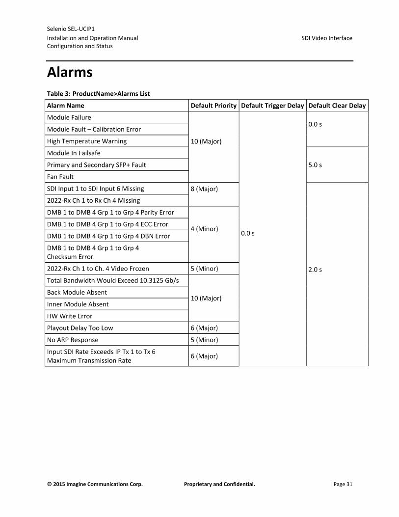
Alarms Table 3: ProductName>Alarms List
Alarm Name Default Priority Default Trigger Delay Default Clear Delay
Module Failure
10 (Major)
0.0 s
0.0 s
Module Fault – Calibration Error
High Temperature Warning
Module In Failsafe
5.0 s Primary and Secondary SFP+ Fault
Fan Fault
SDI Input 1 to SDI Input 6 Missing 8 (Major)
2.0 s
2022‐Rx Ch 1 to Rx Ch 4 Missing
DMB 1 to DMB 4 Grp 1 to Grp 4 Parity Error
4 (Minor)
DMB 1 to DMB 4 Grp 1 to Grp 4 ECC Error
DMB 1 to DMB 4 Grp 1 to Grp 4 DBN Error
DMB 1 to DMB 4 Grp 1 to Grp 4 Checksum Error
2022‐Rx Ch 1 to Ch. 4 Video Frozen 5 (Minor)
Total Bandwidth Would Exceed 10.3125 Gb/s
10 (Major) Back Module Absent
Inner Module Absent
HW Write Error
Playout Delay Too Low 6 (Major)
No ARP Response 5 (Minor)
Input SDI Rate Exceeds IP Tx 1 to Tx 6 Maximum Transmission Rate
6 (Major)

Selenio SEL‐UCIP1
Installation and Operation Manual Laser Safety for Fiber Optic Back Modules
© 2015 Imagine Communications Corp. Proprietary and Confidential. | Page 32
Laser Safety for Fiber Optic Back Modules WARNING! Use of controls, adjustments, and procedures other than those specified in this document may result in hazardous laser radiation exposure.
Optical fiber telecommunication systems use semiconductor laser transmitters that emit infrared light that is normally not visible to the human eye. Although a conventional laser produces a small beam of light, the power density is very high, and it can damage your eyes.
If a beam of laser light enters the eye, the eye magnifies and focuses the energy on the retina. The energy that reaches the retina can be as much as 100,000 times more than at the cornea and, as a result, it can burn the retina.
Laser transmission products are classified in four major groups (Class 1, 2, 3, and 4), according to their emissions and potential for causing injury. Fiber optic transmitter modules in this series are designated Class 1.
Precautions for Enclosed Systems In its normal operating mode, an optical fiber communication system is totally enclosed and presents no risk of eye injury. However, if the fiber optic cables that interconnect various components of an optical fiber disconnect or break, you may be exposed to laser emissions. Also, technicians may be exposed to laser emissions during installation and servicing.
Unlike some other laser designs, semiconductor lasers have a highly divergent beam that decreases rapidly with distance. The greater the distance, the less energy will enter the eye, and the less potential risk for eye injury.
WARNING! Eye damage may occur if an optical instrument such as a microscope, magnifying glass, or eye loupe is used to stare at the energized fiber end.
Under normal operating conditions, optical fiber telecommunication systems are completely enclosed; nonetheless, observe the following precautions:
Do not stare into optical connectors or broken fibers. Ensure technicians have satisfactorily completed an approved training course before performing installation or maintenance.
Ensure there are appropriate warning labels near the optical ports of the modules.

Selenio SEL‐UCIP1
Installation and Operation Manual Label
© 2015 Imagine Communications Corp. Proprietary and Confidential. | Page 33
Precautions for Unenclosed Systems During service, maintenance, or restoration, an optical fiber telecommunication system is considered unenclosed. Under these conditions, follow the practices described below.
CAUTION! Only authorized, trained personnel shall be permitted to do service, maintenance, and restoration.
1. Avoid exposing the eye to emissions from unterminated, energized optical connectors at close distances.
2. Ensure that only authorized, trained personnel use optical test equipment during installation or servicing.
3. Turn off all laser sources before scanning a fiber with an optical test set.
4. Keep all unauthorized personnel away from the immediate area of the optical fiber systems during installation and service.
For guidance on the safe use of optical fiber communication systems in the workplace, consult ANSI Z136.2, American National Standard for Safe Use of Lasers in the U.S. or outside the U.S., IEC‐60825, Part 2.
Label The SEL‐UCIP1 is a Class 1 laser product when used with a fiber optic back module.
Figure 9: Label for Class 1 Laser Products
Inspecting and Cleaning Fiber Optic Connections When connecting fibers to a back module, ensure that you do not touch the end of the fiber, or allow it to become dirty. Small amounts of microscopic dust or other contaminants can seriously impair or disable a fiber optic network. If you touch the end of a fiber prior to connecting it to the back module, or otherwise allow it to become dirty, you must carefully inspect and clean the connection.
This table lists some typical contaminants of a fiber optic connection.

Selenio SEL‐UCIP1
Installation and Operation Manual Inspecting and Cleaning Fiber Optic Connections
© 2015 Imagine Communications Corp. Proprietary and Confidential. | Page 34
Table 4: Typical Contaminants
Contaminant Comments
Dust particle, 1 micron
Can block up to 1% of the light transmission, creating a loss of 0.05 dB
Dust particle, 9 microns
Although microscopic, the particle can completely block the fiber core
Human hair Typically 50 to 75 microns in diameter
Oil Frequently caused by touching
Film residues Can accumulate from vapors or smoke
Powdery coatings Can be left behind after water or other solvents evaporate
Important Points Before you begin cleaning, always inspect the fiber connections. Inspect and clean both fiber ends every time you make a connection.
Keep a protective cap on unplugged fiber connectors. Do not touch the end of a fiber. Store unused protective caps in a clean resealable container, located nearby for easy access. Do not reuse cleaning tissues or swabs. Do not allow alcohol or another wet cleaning agent to dry on a fiber end. Never touch the dispenser tip of an alcohol bottle or any clean portion of a tissue or swab. Use care when handling the fiber; do not twist or pull. Keep your cleaning fluids away from open flame or spark.

Selenio SEL‐UCIP1
Installation and Operation Manual Inspection and Cleaning Procedure
© 2015 Imagine Communications Corp. Proprietary and Confidential. | Page 35
The illustration shows the acceptable limits of defects in a fiber connection.
Figure 10: Fiber Optic Cross‐Section
Inspection and Cleaning Procedure
Inspection To inspect and clean the fibers, follow these steps:
1. Ensure the fiber is not "live."
WARNING! Eye damage may occur if an optical instrument such as a microscope, magnifying glass, or eye loupe is used to stare at an energized fiber end.
2. Inspect the fiber endface with a fiberscope.
3. If the fiber endface is clean, return to the installation instructions; if the connector is dirty, proceed to the dry cleaning instructions below.

Selenio SEL‐UCIP1
Installation and Operation Manual Specifications
© 2015 Imagine Communications Corp. Proprietary and Confidential. | Page 36
Dry Cleaning If you are using cartridge‐ or pocket‐style dry cleaning tools, follow the manufacturer’s directions. If you are using lint‐free wipes, follow these steps:
1. Fold the lint‐free wipe four to eight times into a square, taking care to avoid touching the cleaning surface of the wipe.
2. Lightly wipe the fiber tip in the central portion of the lint‐free wipe.
CAUTION: Do not scrub the fiber. Excessive rubbing will leave scratches.
3. Repeat the wiping action on another clean section of the wipe or a new wipe.
4. Inspect the connector again with the fiberscope.
5. If the connection is clean, return to the installation steps; if the connector is still dirty, proceed to the wet cleaning instructions.
Wet Cleaning Using 99.8% isopropyl alcohol and lint‐free wipes, follow these steps to wet clean the fiber:
1. Fold the wipe into a square, about 4 to 8 layers thick.
2. Moisten one section of the lint‐free wipe with one drop of 99.8% alcohol, ensuring that a portion of the wipe remains dry.
3. Lightly wipe the fiber end in the alcohol‐moistened portion of the lint‐free wipe.
4. Immediately repeat the wiping action on the dry section of the wipe, removing any residual alcohol.
5. Inspect the fiber endface again, and if necessary, repeat the wet cleaning with another clean section of the lint‐free wipe.
CAUTION! Do not scrub the fiber. Excessive rubbing will leave scratches.
6. Dry clean any remaining residue, and then inspect the connector again.
7. If the contamination persists, repeat the dry and wet cleaning procedure until the endface is clean.
If the fiber end still remains dirty after repeated cleaning attempts, call Customer Service for further instructions; if the fiber end is clean, return to the installation instructions.

Selenio SEL‐UCIP1
Installation and Operation Manual Specifications
© 2015 Imagine Communications Corp. Proprietary and Confidential. | Page 37
Specifications
HD/SD‐SDI Input Specifications Table 5: HD/SD‐SDI Input Specifications
Item Specification
Number of Inputs Up to 6 (bi‐directional port shared with output)
Standard HD: SMPTE 292M (1.485, 1.485/1.001 Gb/s)
SD: SMPTE 259M‐C (270 Mb/s, 525/625 component video)
Connector (High‐Density) HD‐BNC
Impedance 75
Signal Level 800 mV ± 10%
Return Loss HD: >15 dB, typical, from 5 MHz to 1485 MHz
SD: >15 dB, typical, from 5 MHz to 270 MHz
Equalization HD: Adaptive cable equalization for >492ft (150m) typical, of Belden 1694A coaxial cable
SD: Adaptive cable equalization for >820 ft (250m) typical, of Belden 1694A coaxial cable
Note: All the unused output ports should be have 75 terminators.
Selenio SEL‐UCIP1
Installation and Operation Manual Specifications
© 2015 Imagine Communications Corp. Proprietary and Confidential. | Page 38
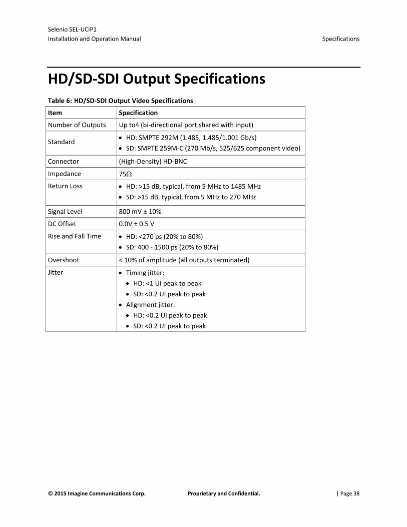
HD/SD‐SDI Output Specifications Table 6: HD/SD‐SDI Output Video Specifications
Item Specification
Number of Outputs Up to4 (bi‐directional port shared with input)
Standard HD: SMPTE 292M (1.485, 1.485/1.001 Gb/s)
SD: SMPTE 259M‐C (270 Mb/s, 525/625 component video)
Connector (High‐Density) HD‐BNC
Impedance 75
Return Loss HD: >15 dB, typical, from 5 MHz to 1485 MHz
SD: >15 dB, typical, from 5 MHz to 270 MHz
Signal Level 800 mV ± 10%
DC Offset 0.0V ± 0.5 V
Rise and Fall Time HD: <270 ps (20% to 80%) SD: 400 ‐ 1500 ps (20% to 80%)
Overshoot < 10% of amplitude (all outputs terminated)
Jitter Timing jitter:
HD: <1 UI peak to peak SD: <0.2 UI peak to peak
Alignment jitter:
HD: <0.2 UI peak to peak SD: <0.2 UI peak to peak

Selenio SEL‐UCIP1
Installation and Operation Manual Specifications
© 2015 Imagine Communications Corp. Proprietary and Confidential. | Page 39
SFP+ Specifications
OP+SFP+TRSM+10G Single Mode Optical Transceiver
Table 7: Specifications for OP+SFP+TRSM+10G Single Mode Optical Transceiver
Transmitter
Parameter Minimum Typical Maximum Unit Notes
Laser OMA Output Power ‐5.2 dBm 1
Laser Mean Output Power ‐8.2 +0.5 dBm 1
Laser Off Power ‐30 dBm 1
Extinction Ratio 3.5 dB 1
Transmitter and Dispersion Penalty (TDP) 3.2 dB 1
Center Wavelength 1260 1355 nm 1
Optical Return Loss Tolerance 12 dB 1
Receiver
Parameter Minimum Typical Maximum Unit Notes
Receiver Sensitivity (OMA) ‐12.6 dBm 1
Stressed Receiver Sensitivity (OMA) ‐10.3 dBm 1,2
Receiver Power Overload +0.5 dBm 1
Receiver Reflectance ‐12 dB 1
Center Wavelength 1260 1355 nm 1
Vertical Eye Closure Penalty 2.2 dB 3
Stressed Eye Jitter 0.3 UIp‐p 3
RX_LOS (OMA) Assert ‐17 dBm 4
RX_LOS (OMA) De‐Assert ‐30 dBm 4
RX_LOS (OMA) Hysteresis 0.5 dB 4
1. IEEE 802.3ae Clause 52 compliant
2. Measured with worst ER; BER<10‐12; 231‐1 PRBS
3. Vertical eye closure and stressed eye jitter are test conditions for stressed sensitivity (OMA) measurement.
4. Loss of Signal (LOS) detection responds only to OMA and the indicator will respond unpredictably with the application of unmodulated optical power.
Selenio SEL‐UCIP1
Installation and Operation Manual Specifications
© 2015 Imagine Communications Corp. Proprietary and Confidential. | Page 40
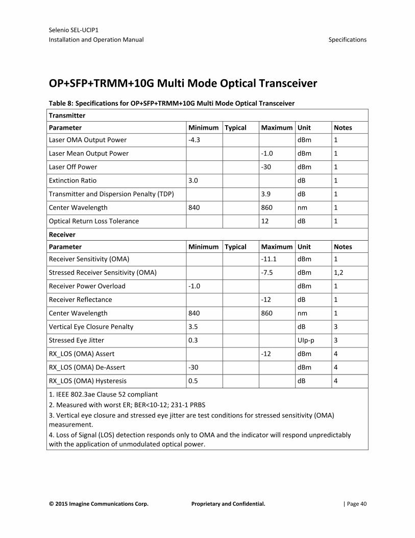
OP+SFP+TRMM+10G Multi Mode Optical Transceiver
Table 8: Specifications for OP+SFP+TRMM+10G Multi Mode Optical Transceiver
Transmitter
Parameter Minimum Typical Maximum Unit Notes
Laser OMA Output Power ‐4.3 dBm 1
Laser Mean Output Power ‐1.0 dBm 1
Laser Off Power ‐30 dBm 1
Extinction Ratio 3.0 dB 1
Transmitter and Dispersion Penalty (TDP) 3.9 dB 1
Center Wavelength 840 860 nm 1
Optical Return Loss Tolerance 12 dB 1
Receiver
Parameter Minimum Typical Maximum Unit Notes
Receiver Sensitivity (OMA) ‐11.1 dBm 1
Stressed Receiver Sensitivity (OMA) ‐7.5 dBm 1,2
Receiver Power Overload ‐1.0 dBm 1
Receiver Reflectance ‐12 dB 1
Center Wavelength 840 860 nm 1
Vertical Eye Closure Penalty 3.5 dB 3
Stressed Eye Jitter 0.3 UIp‐p 3
RX_LOS (OMA) Assert ‐12 dBm 4
RX_LOS (OMA) De‐Assert ‐30 dBm 4
RX_LOS (OMA) Hysteresis 0.5 dB 4
1. IEEE 802.3ae Clause 52 compliant
2. Measured with worst ER; BER<10‐12; 231‐1 PRBS
3. Vertical eye closure and stressed eye jitter are test conditions for stressed sensitivity (OMA) measurement.
4. Loss of Signal (LOS) detection responds only to OMA and the indicator will respond unpredictably with the application of unmodulated optical power.

Selenio SEL‐UCIP1
Installation and Operation Manual Specifications
© 2015 Imagine Communications Corp. Proprietary and Confidential. | Page 41
Power Consumption Table 9: Power Consumption
Item Specification
Module Power Consumption 40 W maximum

Selenio SEL‐UCIP1
Installation and Operation Manual Index
© 2015 Imagine Communications Corp. Proprietary and Confidential.Error! Unknown document property name. | Page 42
Index A Accessing MIBs • 15 Alarms • 31 Allocated Channel Bandwidth (Mbps) • 23 Audio DMB Status • 28 Audio Embedding • 29 Audio Sync • 29
B Back Module • 9 Board and FPGA Temperature • 18 Buffered Packets • 27
C Channel Bandwidth Status • 21 Clear EDH/CRC Error Counter • 22 Clear Packet Counters • 28 Contact Information • 2 Corrected Packets • 27 CTR SDI Out Select • 17 CTR SDI/EXT SDI 1 to EXT SDI 4 Input Status • 30 Current Primary and Secondary IP Address • 25 Current Primary and Secondary UDP Port • 25 Current Primary and Secondary VLAN ID • 26
D DDR Buffer Overflow • 27 Destination IP Address • 22 Destination MAC Address • 23 Destination User Datagram Protocol (UDP) Port
• 22 Dry Cleaning • 35 Duplicate Packets • 27
E EDH or CRC Errors • 22 Examples: • 15
F Failsafe mode • 14 Fan RPM • 18 Features of the product • 7 FEC • 23, 28 FEC Level • 23 FEC Order (4‐255) • 23 FEC Period (4‐1020) • 23
FEC Row Enable • 23 Firmware upgrades • 13, 14 Frame Reference Select • 17 Front Module • 8
G General • 16, 18, 21, 25
H HD/SD‐SDI Input Specifications • 36 HD/SD‐SDI Output Specifications • 37 HD‐BNC Label • 25 How To Set Up an SEL‐UCIP1 • 16
I Important Points • 34 Inspecting and Cleaning Fiber Optic Connections
• 33 Inspection • 35 Inspection and Cleaning Procedure • 35 Installation, Operation, and Specifications • 6 Installing Selenio
modulesIXInstallingSeleniomodules • 11 Installing the Module in an MCP3 Frame • 11 IP Receiver (Table) • 24 IP Receiver Enable • 25 IP to SDI • 24 IP Transmitter (Table) • 20 IP Transmitter Enable • 21 IP WAN (Table) • 18 IP WAN Address • 22 IP WAN Primary and Secondary • 22, 28
L Label • 33 Laser precautions • 32, 33 Laser Safety for Fiber Optic Back Modules • 31 Loss of Video Mode • 29
M Main Features • 7 Maximum Transmission Rate • 21 MCP1 Frames • 12 Minimum Required Playout Delay (ms) • 30 Missing Packets • 28 Module Configuration • 16 Module Fault Alarm Priority • 16 Module I/O Configuration • 16 Module Options • 6

Selenio SEL‐UCIP1
Installation and Operation Manual Index
© 2015 Imagine Communications Corp. Proprietary and Confidential.Error! Unknown document property name. | Page 43
N Name • 16 Next Primary and Secondary IP Address • 26 Next Primary and Secondary UDP Port • 26 Next Source • 26
O OP+SFP+TRMM+10G Multi Mode Optical
Transceiver • 38 OP+SFP+TRSM+10G Single Mode Optical
Transceiver • 37 Out of Range Packets • 28
P Packet Delay Variation (PDV) (ms) • 30 Packet Interval • 27 Playout Delay • 30 Power Consumption • 39 Powering Up a Module • 12 Precautions for Enclosed Systems • 32 Precautions for Unenclosed Systems • 32 Primary and Secondary Payload Rx Rate
(Mbits/sec) • 19 Primary and Secondary Payload Tx Rate
(Mbits/sec) • 19 Primary and Secondary Rx Packets • 19 Primary and Secondary SFP+ Attributes • 20 Primary and Secondary SFP+ Ethernet MAC
Address • 19 Primary and Secondary SFP+ Link Status • 20 Primary and Secondary SFP+ Received Power •
20 Primary and Secondary SFP+ Transmit Signal •
20 Primary and Secondary Tx Packets • 19 Primary and Secondary Type of Service, Time to
Live, Reordered Packets, and Valid Packets • 28
Primary and Secondary Values • 18 Publication Information • 2
R Received Valid IP Packets • 27 Reference Standard • 17 Removing the Module From an MCP3 Frame •
13 RTP Timestamp Difference • 27
S Safety
precautions with lasers • 32 SDI LOS • 21 SDI Source • 21 SDI Standard • 21, 26 SDI to IP • 20 SDI Video Interface Configuration and Status •
30 Seamless Maximum Path Differential (ms) • 30 Seamless Protection Status • 27 Selected Primary and Secondary IP Address • 25 Selected Primary and Secondary VLAN ID • 25 Serial Number • 17 SFP+ • 20 SFP+ Debug Menu • 20 SFP+ Specifications • 37 Signal Flow • 10 Software upgrades • 13, 14 Software, ROM, and FPGA Versions • 17 Specifications • 36 SRC 1 to SRC 8 Control • 29 SRC Status • 29 Status • 19, 26 Support Contact Information • 2 Switch Status • 26
T Tag • 21, 25 Take • 26 Time to Live • 22 Total Allocated Bandwidth (Mbps) • 24 Trademarks • 2 Transmit Interface • 23 Type of Service • 22
U Upgrade Failure Instructions • 14 Upgrading Module Firmware • 13
V Video Frozen • 29 Video Sync • 29
W WAN Configuration and Status • 18 WAN Select • 22, 25 WAN VLAN ID • 22 Wet Cleaning • 35

Selenio SEL‐UCIP1
Installation and Operation Manual Index
© 2015 Imagine Communications Corp. Proprietary and Confidential.Error! Unknown document property name. | Page 44