Selecting a DC Motor - Michigan State University · IV. Motor Design a. What is a DC motor? Motors...
14
Fall 2013 Matthew Stephan Henry Michigan State University College of Engineering Fall 2013 Selecting a DC Motor
Transcript of Selecting a DC Motor - Michigan State University · IV. Motor Design a. What is a DC motor? Motors...
Fall 2013
Matthew Stephan Henry
Michigan State University College of
Engineering
Fall 2013
Selecting a DC Motor

P a g e | 1
I. Abstract
The purpose of this paper is to provide analysis on the process of selecting a DC motor.
It will give thorough descriptions of the principle operations of DC motors. By better
understanding how this type of product works, the process of finding a motor should
become simplified. Comparisons and contrasts will be given for many motor features
aiding this process. The application note should provide clarity on what type of
characteristics to look for and how to better make motor selection decisions.
P a g e | 2
II. Keywords
Armature – the component of the motor that produces power. It can be located on either
the stator or the rotor.
BLDC – brush-less direct current
Brush – mechanism that conducts current in between moving parts and stationary wires.
Brushed Permanent Magnet Motor - contains permanent magnets inside, which
eliminates the need for external field current. This design allows a smaller, lighter, and
energy-efficient Brush Motor.
Brushed Series Wound Motor - speed varies automatically with the load, increasing as
the load decreases.
Brushed Shunt Wound Motor - run at constant speed regardless of the load.
Commutator – mechanism which reverses the direction of current in certain electric
motors.
Direct Current – electrical charge constantly flows in the same direction. Opposite of an
alternating current, where current periodically switches direction.
Electrical Power – electric circuits transferring electrical power at a given rate.
IPM – Internal Permanent Magnet
PWM – Pulse Width Modulation
Rotor – rotating device in an electric motor which rotates about the Brush DC Motor
generating torque among the rotor’s axis.
Stator – the part of the Brush DC Motor that is stationary.
Torque – the ability of a force to rotate a given object about an axis or fulcrum.

P a g e | 3
Table of Contents
I. Abstract ........................................................................................................................ 1
II. Keywords ................................................................................................................. 2
III. Introduction .............................................................................................................. 4
IV. Motor Design ........................................................................................................... 4
a. What is a DC motor? ................................................................................................... 4
b. Brushed vs. Brushless DC Motors ............................................................................... 5
c. Hall Effect Sensors vs. Back EMF .............................................................................. 6
d. MCU Based Design vs. Standalone Solution .............................................................. 8
e. Commutation Methods .............................................................................................. 11
V. Conclusions ............................................................................................................ 12
VI. References .............................................................................................................. 13

P a g e | 4
III. Introduction
The goal of this application note is to allow the reader to make better decisions when
researching the type of motor to select for a project. I will begin by providing a
description of what a DC motor is and comparing Brushed versus Brushless DC motors.
From there I will go into specific features of motors for example their sensor capabilities,
micro-controller use, and commutation method. I will also provide examples of motor
applications. Finally, I will end with a conclusion of what steps to take with the provided
information. Usually, a motor selection involves many more factors than are presented
here. This method, however, provides the designer with a starting point for the selection
of motors for a particular set of design options.
IV. Motor Design
a. What is a DC motor? Motors are seen everywhere in the world today. Almost every mechanical movement
seen in your daily life is caused thanks to some type of AC or DC motor. A DC motor is
a mechanically commutated electric motor powered from “direct current” hence the
“DC”. There are many types of DC motor architectures but I will explain the basic type
of motor you will see in typical daily applications. These motors are comprised of six
main components; permanent magnets called the stator, a spinning armature called a
rotor, an axle, a commutator, field magnets, and brushes (optional) [1]. The motor uses
magnetism to create rotational motion and spin the axle. By connecting a battery, current
is allowed to flow which will generate an electric field. This is then placed within
another external electric field that is constantly “flipping” directions causing the rotation.
When power is applied, the polarities of the energized winding and the stator magnets are
misaligned, and the rotor will rotate to try and get aligned with the stator's field magnets
[2]. The rotation reverses the direction of current through the rotor winding, leading to a

P a g e | 5
"flip" of the rotor's magnetic field, driving it to continue rotating. The simplest form of
this is done with only 2 poles, however there can be many more poles in application. It is
possible to have many different connections of the field and armature winding which
provides for diverse speed/torque characteristics. Many motors have feedback sensors
which provide information on the performance characteristics. These and other features
will be described in the following sections. All of these choices must be factored when
choosing what type of motor to use.
b. Brushed vs. Brushless DC Motors There are two main types of DC motors. The first and increasingly popular choice today,
is a Brushless DC motor. This type of motor has permanent magnets in the rotor and
stationary electrical current coil magnets on the housing of the motor to act as the stator.
You may then use a motor controller to convert the DC input power to output AC. A
brushed motor on the other hand generates torque directly from DC power supplied to the
motor by using internal commutation, stationary magnets and rotating electrical magnets
[3]. Some advantages of brushed versus brushless are seen in the table of Figure 1 below.
Figure 1 – Advantages of Brushed vs. Brushless DC Motors
Advantages Disadvantages
Cheaper initial cost Brushes eventually wear out
Older/ Easier to Find Sparking/Electrical Noise due to making/breaking connections
Simple Construction - No controller necessary Brushes Limit Maximum speed of motor
Quick Application Harder to cool with internal, centered electromagnet
Limit to # of poles possible
Less Reliable
Better Speed vs Torque Characteristics Higher Start-up Cost
Saves money over time Can become difficult to operate with motor controller
Less Maintenance/More Reliable Most drivers slow BLDC motors by applying reverse current
Noiseless Operation Nearly as much power is used to stop the motor as to start it
Better Speed Ranges
Brushed
Brushless
P a g e | 6
c. Hall Effect Sensors vs. Back EMF
Another important feature of DC motors is the ability to generate feedback. These
sensors provide information on the current, position, speed and direction of a rotating
motor. This is a very useful tool to ensure that you are providing the correct amount of
torque and speed to your circuit. The two main methods for providing this feedback are
Hall-Effect Sensors and Back EMF. Hall Effect sensors are easier to implement and
require the least amount of effort for the user. The sensors main purpose is to convey
information about the rotor’s position at any instance in time. This is done via the Hall
Effect which basically states that there will be a voltage difference between sides of a
conductor when an electrical current passes through. If the magnetic field is known, the
hall voltage can be measured to determine the distance from the conductor. This effect is
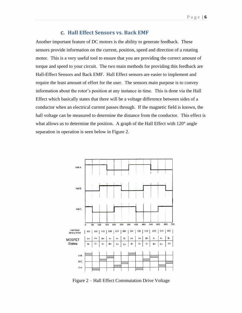
what allows us to determine the position. A graph of the Hall Effect with 120° angle
separation in operation is seen below in Figure 2.
Figure 2 – Hall Effect Commutation Drive Voltage

P a g e | 7
This table represents the state of the high-side and low-side MOSFETs of the half-bridge
amplifiers for all three phases during trapezoidal commutation [4]. When the sensors read
the speed, position, etc… you can then send them to the controller which will adjust these
readings to achieve the desired parameters.
The back electro-magnetic-force (EMF) method on the other hand, does not require any
additional sensors. This implementation however, is much more complicated and has to
overcome several issues. This method is achieved by obtaining the speed and position of
the motor directly from the voltage at the motor windings. This back EMF is created
when the motor’s armature turns, which creates an electrical pulse that is sensed as a
voltage through a resistor. The amplitude of the EMF signal increases with the speed of
the armature rotation. The back EMF voltage can either produce a sine or trapezoidal
waveform which is then sensed at the motor’s winding and typically converted into a
digital square wave by a comparator circuit [5]. You can then use a microcontroller to
calculate the motor position and phase relationship from these generated square waves.
Comparisons of the Hall Effect Sensor vs. Back EMF outputs are shown in Figure 3
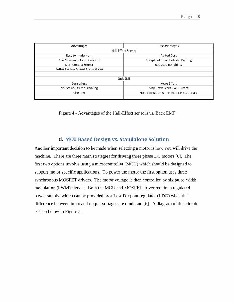
while Figure 4 compares advantages and disadvantages.
Figure 3 - Hall sensor output compared with back EMF for three-phase BLDC motor
P a g e | 8
Figure 4 - Advantages of the Hall-Effect sensors vs. Back EMF
d. MCU Based Design vs. Standalone Solution
Another important decision to be made when selecting a motor is how you will drive the
machine. There are three main strategies for driving three phase DC motors [6]. The
first two options involve using a microcontroller (MCU) which should be designed to
support motor specific applications. To power the motor the first option uses three
synchronous MOSFET drivers. The motor voltage is then controlled by six pulse-width
modulation (PWM) signals. Both the MCU and MOSFET driver require a regulated
power supply, which can be provided by a Low Dropout regulator (LDO) when the
difference between input and output voltages are moderate [6]. A diagram of this circuit
is seen below in Figure 5.
Advantages Disadvantages
Easy to Implement Added Cost
Can Measure a lot of Content Complexity due to Added Wiring
Non-Contact Sensor Reduced Reliability
Better for Low Speed Applications
Sensorless More Effort
No Possibility for Breaking May Draw Excessive Current
Cheaper No Information when Motor is Stationary
Hall Effect Sensor
Back EMF

P a g e | 9
Figure 5 – Application Example of a MCU-based Design for 3-Phase BLDC Motor
Another MCU-based design would be to use a pre-driver with a companion IC to perform
the tasks from the previous option [6]. Power management, sensing, and communication
can all be done through the pre-driver to accomplish all of its tasks. This can be an ideal
solution as it optimizes the system performance. There are many configurations where
the MCU and IC are together in one package simplifying the design. Texas Instruments
and many other product designers develop this type of hardware. The main difficulties
with this option are programming the motor controller and communicating between the
two. An example of this circuit is shown in Figure 6.
P a g e | 10
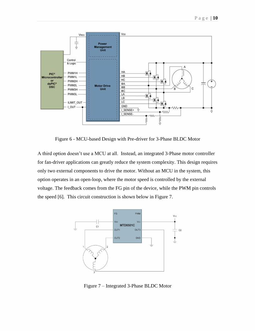
Figure 6 - MCU-based Design with Pre-driver for 3-Phase BLDC Motor
A third option doesn’t use a MCU at all. Instead, an integrated 3-Phase motor controller
for fan-driver applications can greatly reduce the system complexity. This design requires
only two external components to drive the motor. Without an MCU in the system, this
option operates in an open-loop, where the motor speed is controlled by the external
voltage. The feedback comes from the FG pin of the device, while the PWM pin controls
the speed [6]. This circuit construction is shown below in Figure 7.
Figure 7 – Integrated 3-Phase BLDC Motor

P a g e | 11
Advantages of each of these options are listed in the table below.
Figure 8 – Advantages of 3-Phase BLDC Motor Driver Options
e. Commutation Methods
Another important question to consider in motor selection is the type of commutator to
use. The three most basic choices are sinusoidal, trapezoidal, or field oriented control
(FOC). Sinusoidal versus trapezoidal basically reference the shape of the waveform that
is driving the motor. Trapezoidal tends to be better for high-speed torque control while
sinusoidal is better at low speeds. Part of this is due to the fact that sinusoidal doesn’t
have the torque ripple at low speeds that you would see for trapezoidal. Field oriented
control, on the other hand, is more suitable for high-end application due to the complex
design and higher processing requirements [7]. It commutates the motor by calculating
the voltage and current based on feedback, and maintains high efficiency allowing for
precise control of speed and torque. Advantages of each of these three options are shown
below in Figure 9.
Figure 9 - Advantages of Different Commutation Methods [8]
MCU + Discrete Circuit MCU + Pre-Driver Integrated
System Complexity High Moderate Low
PCB Board Space Large Moderate Small
Flexibility High Moderate Low
Required Design Experience High High Moderate
Easy Adaption to Different Application High Moderate Low

P a g e | 12
V. Conclusions
There are many other factors that you can consider in motor selection. Hopefully this
application note will provide a god start to the process. Once all the above decisions
have been made, the next choices become: “what is the application of the motor?”, “how
powerful do you want it to be?”, and finally, “what size motor will fit your product?”.
Once these decisions have been made you can narrow your choice by the amount you
want to spend and find the best price.

P a g e | 13
VI. References
[1] http://www.solarbotics.net/starting/200111_dcmotor/200111_dcmotor2.html
[2] http://electronics.howstuffworks.com/motor5.htm
[3] http://www.anaheimautomation.com/manuals/forms/brush-dc-motor-guide.php
[4] http://www.pmdcorp.com/support/application_notes/brushlessConfiguration.cfm
[5] http://ww1.microchip.com/downloads/en/AppNotes/00894a.pdf
[6] http://www.ecnmag.com/articles/2012/04/selecting-best-three-phase-bldc-motor-
design-technique
[7] http://www.magnelab.com/uploads/4c51d9ba6fe5a.pdf
[8] http://machinedesign.com/motorsdrives/selecting-dc-brush-and-brushless-motors