SELECTED ASPECTS OF CALCULATING CRANE SUPPORTING …
14
CZASOPISMO INŻYNIERII LĄDOWEJ, ŚRODOWISKA I ARCHITEKTURY JOURNAL OF CIVIL ENGINEERING, ENVIRONMENT AND ARCHITECTURE JCEEA, t. XXXII, z. 62 (3/II/15), lipiec-wrzesień 2015, s. 135-148 Grzegorz GREMZA 1 Jan ZAMOROWSKI 2 SELECTED ASPECTS OF CALCULATING CRANE SUPPORTING BEAMS During the last few years the European Standards (EN) for designing the overhead crane beams has been introduced by many countries. The general design approach and detailed guidelines presented in these documents are partly different from the previous obligatory national design rules. The calculation based on new rules mostly reveals greater use of the terms of the load capacity, especially it concerns the fatigue load capacity. Such a results lead to designing of the oversized cross- section. On the other hand the investors’ requirements to extremely reduce the weight of the construction is a big challenge to the structural engineers and that enforced them to design the constructions without any reserve of the load capacity. In such a context the legitimacy of the simplified calculation method that has been used so far is discussed in this paper. For this purpose the exemplary calculations of beams with varied cross-sections by use of the precise and simpli- fied method were executed. The conclusions concerning differences in stresses values resulting from acceptance of simplified model have been shown. The is- sues connected with the assessment of the fatigue load capacity are mentioned also in this paper especially focusing on the load capacity of the elements with holes. The American and European standards and another guidelines have been analysed in the aforementioned context and compared with accessible test results. Keywords: fatigue life, construction details with holes, simplified method, stress 1. Calculating the normal stresses 1.1. Traditional simplified and precise method So far according to the Polish Standard [1] and outlines using in other coun- tries, eg. [11], the simplified model was used to check the load capacity of the beams with a brace. Such an approach was based on the independent stress check- ing in the main runway beam and in the horizontal brace. The horizontal brace _____________________________________ 1 Author for correspondence: Grzegorz Gremza, Silesian University of Technology, 44-100 Gli- wice, ul. Akademicka 5, 662349538, [email protected]. 2 Jan Zamorowski, University of Bielsko-Biała, ATH, 43-309 Bielsko-Biała, ul. Willowa 2, zam- [email protected].
Transcript of SELECTED ASPECTS OF CALCULATING CRANE SUPPORTING …

CZASOPISMO INŻYNIERII LĄDOWEJ, ŚRODOWISKA I ARCHITEKTURY JOURNAL OF CIVIL ENGINEERING, ENVIRONMENT AND ARCHITECTURE
JCEEA, t. XXXII, z. 62 (3/II/15), lipiec-wrzesień 2015, s. 135-148
Grzegorz GREMZA1 Jan ZAMOROWSKI 2
SELECTED ASPECTS OF CALCULATING CRANE SUPPORTING BEAMS
During the last few years the European Standards (EN) for designing the overhead crane beams has been introduced by many countries. The general design approach and detailed guidelines presented in these documents are partly different from the previous obligatory national design rules. The calculation based on new rules mostly reveals greater use of the terms of the load capacity, especially it concerns the fatigue load capacity. Such a results lead to designing of the oversized cross-section. On the other hand the investors’ requirements to extremely reduce the weight of the construction is a big challenge to the structural engineers and that enforced them to design the constructions without any reserve of the load capacity. In such a context the legitimacy of the simplified calculation method that has been used so far is discussed in this paper. For this purpose the exemplary calculations of beams with varied cross-sections by use of the precise and simpli-fied method were executed. The conclusions concerning differences in stresses values resulting from acceptance of simplified model have been shown. The is-sues connected with the assessment of the fatigue load capacity are mentioned also in this paper especially focusing on the load capacity of the elements with holes. The American and European standards and another guidelines have been analysed in the aforementioned context and compared with accessible test results.
Keywords: fatigue life, construction details with holes, simplified method, stress
1. Calculating the normal stresses
1.1. Traditional simplified and precise method
So far according to the Polish Standard [1] and outlines using in other coun-tries, eg. [11], the simplified model was used to check the load capacity of the beams with a brace. Such an approach was based on the independent stress check-ing in the main runway beam and in the horizontal brace. The horizontal brace _____________________________________
1 Author for correspondence: Grzegorz Gremza, Silesian University of Technology, 44-100 Gli-wice, ul. Akademicka 5, 662349538, [email protected].
2 Jan Zamorowski, University of Bielsko-Biała, ATH, 43-309 Bielsko-Biała, ul. Willowa 2, [email protected].
G. Gremza, J. Zamorowski 136
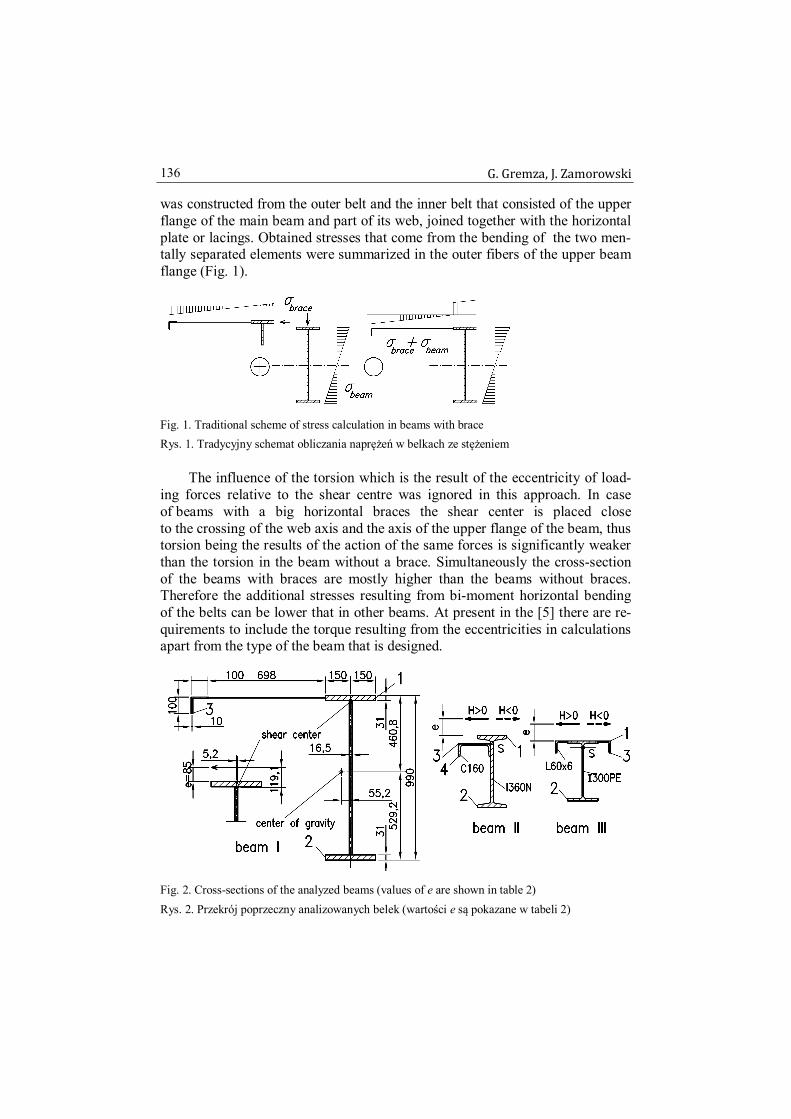
was constructed from the outer belt and the inner belt that consisted of the upper flange of the main beam and part of its web, joined together with the horizontal plate or lacings. Obtained stresses that come from the bending of the two men-tally separated elements were summarized in the outer fibers of the upper beam flange (Fig. 1).
Fig. 1. Traditional scheme of stress calculation in beams with brace Rys. 1. Tradycyjny schemat obliczania naprężeń w belkach ze stężeniem
The influence of the torsion which is the result of the eccentricity of load-ing forces relative to the shear centre was ignored in this approach. In case of beams with a big horizontal braces the shear center is placed close to the crossing of the web axis and the axis of the upper flange of the beam, thus torsion being the results of the action of the same forces is significantly weaker than the torsion in the beam without a brace. Simultaneously the cross-section of the beams with braces are mostly higher than the beams without braces. Therefore the additional stresses resulting from bi-moment horizontal bending of the belts can be lower that in other beams. At present in the [5] there are re-quirements to include the torque resulting from the eccentricities in calculations apart from the type of the beam that is designed.
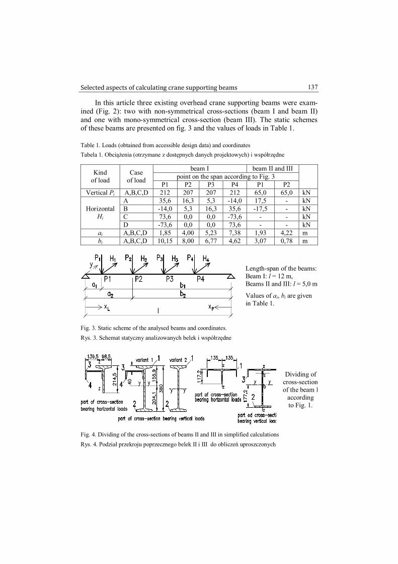
Fig. 2. Cross-sections of the analyzed beams (values of e are shown in table 2) Rys. 2. Przekrój poprzeczny analizowanych belek (wartości e są pokazane w tabeli 2)
Selected aspects of calculating crane supporting beams 137
In this article three existing overhead crane supporting beams were exam-ined (Fig. 2): two with non-symmetrical cross-sections (beam I and beam II) and one with mono-symmetrical cross-section (beam III). The static schemes of these beams are presented on fig. 3 and the values of loads in Table 1.
Table 1. Loads (obtained from accessible design data) and coordinates Tabela 1. Obciążenia (otrzymane z dostępnych danych projektowych) i współrzędne
beam I beam II and III point on the span according to Fig. 3 Kind
of load Case
of load P1 P2 P3 P4 P1 P2
Vertical Pi A,B,C,D 212 207 207 212 65,0 65,0 kN A 35,6 16,3 5,3 -14,0 17,5 - kN B -14,0 5,3 16,3 35,6 -17,5 - kN C 73,6 0,0 0,0 -73,6 - - kN
Horizontal Hi
D -73,6 0,0 0,0 73,6 - - kN ai A,B,C,D 1,85 4,00 5,23 7,38 1,93 4,22 m bi A,B,C,D 10,15 8,00 6,77 4,62 3,07 0,78 m
Length-span of the beams: Beam I: l = 12 m, Beams II and III: l = 5,0 m
Values of ai, bi are given in Table 1.
Fig. 3. Static scheme of the analysed beams and coordinates. Rys. 3. Schemat statyczny analizowanych belek i współrzędne
Dividing of cross-section of the beam I
according to Fig. 1.
Fig. 4. Dividing of the cross-sections of beams II and III in simplified calculations Rys. 4. Podział przekroju poprzecznego belek II i III do obliczeń uproszczonych

G. Gremza, J. Zamorowski 138
For the more accurate calculations, including warping torsion, the normal stresses (excluding the influence of lateral-torsional buckling) are the sum of the stresses resulting from bi-directional bending and bi-moments as follows:
.
I
BI
yMI
zM i
z
iz
y
iy (1)
where: My, Mz – bending moments in the major and minor axis, Iy, Iz – second moments of inertia in the major and minor axis, yi, zi – the distance from gravity center to the point i of the cross-section, ωi – the sectorial area at a specified point of the cross-section, B – bi-moment, Iω – warping constant of the cross-section.
The values of the bi-moments are calculated by formulas (2a) or (2b):
),sinh()sinh(
)(sinh(L
iTi kxkl
alkk
MB (2a)
),sinh()sinh(
)(sinh(P
iTi kxkl
blkk
MB (2b)
in which: k – flexural-bending characteristic, l – span of the beam, ai, bi – position of the torque load at the length of the beam, xL, xP – position of the analysed cross-section (coordinates were shown on Fig. 3). Formulas 2a or 2b are used depending on the position of the cross-section, for which the value of the bi-moment was determined, relative to the place where torque loads have been applied to the beam. Obtained values of the stress in selected points of the cross section of the beam according the fig. 2 are presented in the table 2. For the beam I dif-ferences of the stress values between two verified models reach a few percent. In case of the other beams with similar cross-sections the alike results were re-ceived. For the beams II and III the results between the stresses that ware ob-tained by the precise method and simplified method, were grater than for beam I.

Selected aspects of calculating crane supporting beams 139
Table 2. Calculated maximum values of stresses for all cases of loads Tabela 2. Obliczone wartości maksymalne naprężeń dla wszystkich przypadków obciążeń
e = 40 mm (beam II and III) e = 85 mm (beam I) e = 140 mm (beam II and III)
Precise Simplified % Precise Simplified % Bea
m Point
acc. to Figures 2 and 4 MPa MPa - MPa MPa -
1 -210 -188 10,7 - - - 2 179 161 9,9 - - - I
3 - - - - - - 1 -167 -146 12,3 -176 -146 16,8 2 129 87 32,4 112 87 22,0 3 -119 -162 -36,3 -124 -162 -30,4
II –
var.1
4 -106 -134 -26,3 -129 -134 -4,4 1 -167 -168 -0,8 -176 -168 4,4 2 129 88 31,5 112 88 21,0 3 -119 -112 5,4 -124 -112 9,5
II –
var.2
4 -106 -112 -5,8 -129 -112 12,5 1 -240 -237 1,2 -263 -237 9,9 2 184 165 10,2 291 165 43,3
III
3 -215 -181 15,7 -280 -181 35,3
1.2. Simplified method according to Eurocode
According to Eurocode [5], the influence of the torque moment should be included in calculation of the runway beams for overhead cranes. In calculation model assumed in the Eurocode the influence of bi-moment resulting from warping torsion may be replaced by the influence of the additional loads HMT acting on the upper and lower flange of the beam and replacing torque moment MT. The loads HMT can be calculated according to the formula (location of these loads has been shown in Fig. 5):
,h
MH TiMT (3)
where: h – axial spacing of the I-beam flanges.
Fig. 5. Location of additional loads HMT replacing torque loads (EC Model) Rys. 5. Położenie dodatkowych obciążeń HMT zastępujących obciążenie skręcające (EC Model)

G. Gremza, J. Zamorowski 140
The calculation results for selected points of cross-section according to the standard simplified and precise calculation models including the influ-ence of bi-moment have been presented in the table 3. As we can see, the stress values in the lower flange are even up to 144% (for H < 0) greater in EC model than those in precise model (that include the bi-moment) in case of beam II with high rail and about 63% in case of beam III.
Table 3. Max. values of stress including bi-moments and bending moments of flanges from HMT Tabela 3. Maksymalna wartości naprężeń wywołanych bimomentem i momentem zginającym pas
od siły HMT
e = 40 mm e = 140 mm Precise
(Vlasov) Simplified
(EC) %
Precise (Vlasov)
Simplified (EC)
%
Bea
m Point
acc. to Fig. 2
MPa MPa - MPa MPa - 1 -167 -163 1,8 -176 -187 -6,4 2 129 166 -28,3 112 271 -142 3 -119 -187 -57,0 -124 -220 -76,8
II–
var.1
4 -106 -159 -49,5 -129 -192 -49,4 1 -240 -269 -11,9 -263 -311 -18,1 2 184 296 -61,2 291 474 -62,9
III
3 -215 -213 1,1 -280 -255 9,0
2. Fatigue
2.1. Introductory remarks
As the result of the introducing the new design rules [3], [4], [5] the size of the beam cross-sections has increased in comparison to the beams that were designed according to the previous rules. Such a situation results from the ne-cessity of the reduction of the stresses in the cross-section due to the changes of the fatigue categories and higher values of the safety factors. The latter issue that has an influence on the situation is the obligation to take the local bending of the web into consideration during the assessment of fatigue resistance. A lot of doubts has arisen among the structural engineers because of the changes between [1] and [4], especially it considers the considerable changes of the fatigue categories for the elements with holes and the limitation of the possibility to reduce the compressive stresses range by 40%.
2.2. Fatigue capacity of elements with holes – Standard rules
For joining the rail to the runway beam the rail clamps (clips) and bolts are often used and sometimes the secondary elements are also connected
Selected aspects of calculating crane supporting beams 141
to the runway beams by bolts. So far the Polish Standard [1] has contained a few regulations that consider the fatigue load-bearing beam with holes capac-ity. More detailed rules has been introduced in standard [4] and [6].
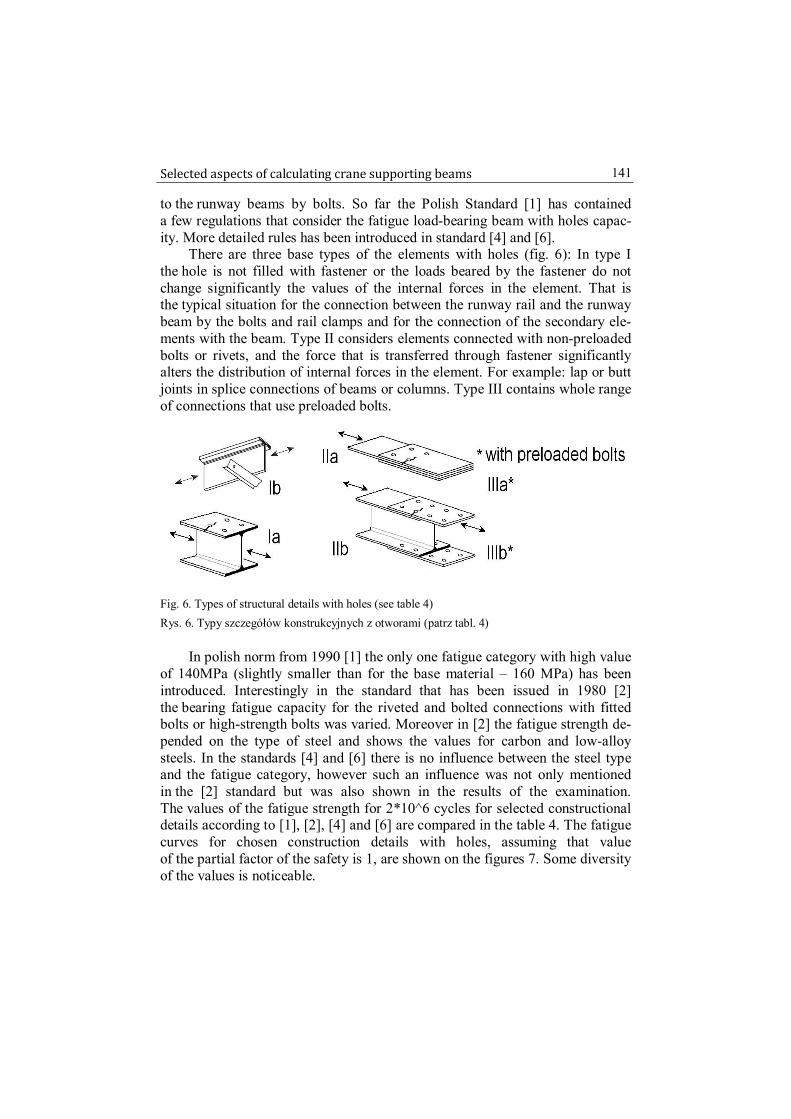
There are three base types of the elements with holes (fig. 6): In type I the hole is not filled with fastener or the loads beared by the fastener do not change significantly the values of the internal forces in the element. That is the typical situation for the connection between the runway rail and the runway beam by the bolts and rail clamps and for the connection of the secondary ele-ments with the beam. Type II considers elements connected with non-preloaded bolts or rivets, and the force that is transferred through fastener significantly alters the distribution of internal forces in the element. For example: lap or butt joints in splice connections of beams or columns. Type III contains whole range of connections that use preloaded bolts.
Fig. 6. Types of structural details with holes (see table 4) Rys. 6. Typy szczegółów konstrukcyjnych z otworami (patrz tabl. 4)
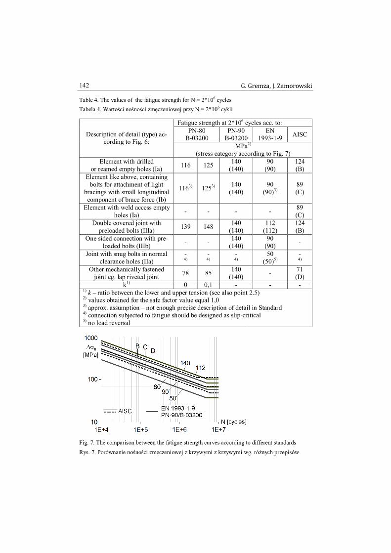
In polish norm from 1990 [1] the only one fatigue category with high value of 140MPa (slightly smaller than for the base material – 160 MPa) has been introduced. Interestingly in the standard that has been issued in 1980 [2] the bearing fatigue capacity for the riveted and bolted connections with fitted bolts or high-strength bolts was varied. Moreover in [2] the fatigue strength de-pended on the type of steel and shows the values for carbon and low-alloy steels. In the standards [4] and [6] there is no influence between the steel type and the fatigue category, however such an influence was not only mentioned in the [2] standard but was also shown in the results of the examination. The values of the fatigue strength for 2*10^6 cycles for selected constructional details according to [1], [2], [4] and [6] are compared in the table 4. The fatigue curves for chosen construction details with holes, assuming that value of the partial factor of the safety is 1, are shown on the figures 7. Some diversity of the values is noticeable.
G. Gremza, J. Zamorowski 142
Table 4. The values of the fatigue strength for N = 2*106 cycles Tabela 4. Wartości nośności zmęczeniowej przy N = 2*106 cykli
Fatigue strength at 2*106 cycles acc. to: PN-80
B-03200 PN-90
B-03200 EN
1993-1-9 AISC Description of detail (type) ac-cording to Fig. 6: MPa2)
(stress category according to Fig. 7) Element with drilled
or reamed empty holes (Ia) 116 125 140 (140)
90 (90)
124 (B)
Element like above, containing bolts for attachment of light
bracings with small longitudinal component of brace force (Ib)
1163) 1253) 140 (140)
90 (90)3)
89 (C)
Element with weld access empty holes (Ia) - - - - 89
(C) Double covered joint with
preloaded bolts (IIIa) 139 148 140 (140)
112 (112)
124 (B)
One sided connection with pre-loaded bolts (IIIb) - - 140
(140) 90
(90) -
Joint with snug bolts in normal clearance holes (IIa)
-
4) -
4) -
4) 50
(50)5) - 4)
Other mechanically fastened joint eg. lap riveted joint 78 85 140
(140) - 71 (D)
k1) 0 0,1 - - - 1) k – ratio between the lower and upper tension (see also point 2.5)
2) values obtained for the safe factor value equal 1,0
3) approx. assumption – not enough precise description of detail in Standard
4) connection subjected to fatigue should be designed as slip-critical
5) no load reversal
Fig. 7. The comparison between the fatigue strength curves according to different standards Rys. 7. Porównanie nośności zmęczeniowej z krzywymi z krzywymi wg. różnych przepisów

Selected aspects of calculating crane supporting beams 143
According to the American Standard [6] the expected number of cycles lead-ing to destruction under determined stress level has considered only the elements with the drilled or sub-punched and reamed holes. In the Eurocode [4] such an information was not given in extenso in the description of the construction de-tails category. According the EN 1090-2 there is a possibility to perform the con-struction in EXC2 class assuming the low consequence class CC1 according to EN 1990-2. One must emphasize that in the EXC2 class there are no require-ments to ream the holes and thus the real fatigue category can be slightly lower. Moreover if the class of the construction is not provided, the construction is per-formed in the EXC2 class. Thus the whole elements exposed to the fatigue should be designed as the EXC3 class.
2.3. The researches on the fatigue life of the plate elements with holes
Taking into account the possibility of accelerating the production process by punching the holes, for the elements that are exposed to fatigue, the re-searches focusing on the fatigue life of the aforementioned elements has been conducted [7], [10], [13], [16]. The results of the research for the elements with punched holes have indicated that their fatigue strength is located between the curves D and B (compare Fig. 7), which more or less corresponds to the 80 and 112 categories, exceptionally the fatigue strength is slightly below the curve D. For the elements with drilled holes the results were always over the curve C and frequently even little over the curve B, however the examination based on number of cycles greater than 1*10^6 revealed that the bearing capacities of the elements has been always over the curve B. The influence of the pre-loaded bolt used in plate with holes (bolt is not the connector) gaining the slight increase of the fatigue strength is mentioned in [8]. However one should note that the number of cycles to failure (fatigue life) of the element with holes drilled by worn drill bit may be nearly the same as in the element with punched holes [10]. Thus it is very important to provide the right quality to the hole sur-face. The Standard EN 1090-2 provides the reference to the ISO standard that concerns the issues of the surface quality after cutting and polishing. Notwith-standing the authors of [13] indicates that the result discrepancies between fa-tigue life of the elements with drilled and punched elements might not fit to the matter of fact due to the high quality of the laboratory obtained drilled holes. However the less deformability and slightly less bearing-capacity is ob-tained for the elements with punched holes even under the static loads. In the papers [16] and [17] the extensive studies for the galvanized and not gal-vanized samples with punched and drilled holes has been described. The fa-tigue strength values of the galvanized samples were over the curve provided for the category 71, and for not-galvanized samples over the curve for the cate-gory 90.

G. Gremza, J. Zamorowski 144
2.4. The researches on the fatigue life of the lap joints and butt joints
A significant amount of results gathered in [13] revealed that the bearing capacity of the butt joints with 2, 4 and 6 snug bolts or pre-loaded bolts on one side of them mostly were over the curve B. The curve B within about 4,5*10^6 cycle numbers is between 112 and 140 category according to [4] and [1]. Be-yond that range the curve B correspond to the slightly higher curve than was established for 140 category (compare Fig. 6). Similar result concerning the pre-tensioned connections has been presented in [10]. Nevertheless in case of the single bolted or double bolted butt joints with 2 or 4 non-preloaded bolts, the fatigue stress capacity of the connection with punched and drilled holes re-sembled the curve B (revealing some fluctuation of the values). The authors [10], [13] have classified such a connection to the D category that corresponds to the 71 category according to [4]. The bearing capacities for one bolt connec-tion with two splices for the not-galvanized elements with drilled holes pre-sented in [17] correspond to the curve for 71 category, and for the galvanized elements with the punched holes slightly above the curve 36. The adverse influ-ence of the galvanization process was reduced due to the use of high-strength bolts in the connection. Generally most of the authors suggest that the influence of the reaming or galvanization is utterly insignificant in the pre-tensioned con-nection. The separate issue is use of the resin injected bolts. Less bearing capac-ity has been obtained for the elements that contain the bolts with injection than for elements with standard bolt at the same rate of the tightening moment.
2.5. The influence of the reversal loading and compressive stresses
The researches that were presented in many papers mostly were conducted under the tensile fluctuating load with the constant amplitude and for ratio be-tween the lower and upper tension in the net section equal about 0,1 e.g. [10], [17]. Sometimes it was from 0,1 up to 0,4 with constant ratio between minimum stress and yield stress equal 0,1. Non-reversal fluctuating load is typical for runway beams and in that context the results interpretation can be useful for the assessment of the stress category. However, the full stress range has not been included in that researches. Furthermore, there is a significant difference in a durability of the compressed and tensioned sample under the same absolute value of the maximum stress, that was included in Polish Standards [1], [2]. The included recommendations fit to the many results that were quoted in [13] and [15], where it was concluded that the reduction of the compressive stress range by 40% under the reversal load for the bolted and riveted connections should be taken into consideration.

Selected aspects of calculating crane supporting beams 145
2.6. The slope of the fatigue curves for bolted joints
The whole results for the bolted connections indicated that the slope of fa-tigue curves is smaller than presented in Eurocodes [4] and American standards [6]. Suggested changes concerning the fatigue curves have been presented in [17].
2.7. Fatigue life of the old connections
A lot of attention has been paid to the bear capacity of the old riveted struc-tures. Also the runway beams from the 30s of the twentieth century are still used. In the paper [15] the category C for the new drilled elements has been in-troduced apart from the age of the steel and the category D for the assessment of the connection with the old holes has been introduced. Such a conclusion does not concern the wrought steel. In the [12] the fatigue category 71 is rec-ommended, independently of the hole performing. Those recommendations cor-respond with the results of the researches shown in [9]. In some cases category 63 is possible [14]. The shape of the fatigue curve for the riveted connections otherwise than for the bolted connections correspond to that proposed in [4] and [6]. According to the conclusions that are shown in [14], the influence of the holes performing is not enough to differentiate the fatigue categories. More advanced method of assessment the old structures durability are described in [12].
3. Conclusions
3.1. Normal stresses calculation
Three models of overhead cranes runway beams has been discussed in that paper. In the simplified model the upper flange fiber stresses are obtained from the sum of both vertically loaded beam and horizontally loaded brace. In the more precise model the influence of the bi-directional bending and the Saint-Venant and warping torsion is included. In the European stan-dards the influence of the bi-moment may be replaced by the influence of the horizontal bending of the beam flanges loaded additionally with the sub-stitute loading forces HMT. The use of the simplified method of calculating the beams with the broad horizontal braces (as shown in Fig. 1a) according to [1] can be considered appropriate under condition of 10% stock of the beam load capacity. The assumed reserve of load capacity is derived from a few per-centage lowering of the stress values in the critical cross-section which is a re-sult of use of the simplified model (Fig.1). That difference can by reduce by including additional loads HMT acting to the flanges as is assumed in Euro-code [4]. The application of aforementioned method for beams with a smaller brace as shown in Fig. 1b may be not appropriate, however it was permitted

G. Gremza, J. Zamorowski 146
in Polish Standard [1]. The force HMT acting on the lower flange of the simply supported beam caused overestimation of the normal stress values in the lower flange about % in comparison to the calculation model with bi-moment. The simplified method of including the bi-moment assumed in Eurocode (as seen on Fig. 5) is accurate for the shell beam models.
Taking into account the market necessity of utilization the maximal load capacity of the beams, using the more precise calculation models including the warping torsion may be reasonable, what is accessible and comfortable nowadays because of computer programs. The geometrical characteristics of the cross-section or the shell models can be modeled in a very quick way. However there are no widely available computer programs which enable to model the bidirectional bended rod with Saint-Venant and warping torsion to determine in a simple way the influence of bi-moment to the state of utiliza-tion of load capacity of the overhead crane runway beams.
3.2. Fatigue
The changes introduced in Eurocode concerning the fatigue calculation seem to be the most important to construct the shape of the beams. Among the whole doubts reported by structural engineers, the issues of the fatigue cate-gory qualification for the beam with holes has been presented in this paper.
Based on the accessible results it can be concluded that the fatigue catego-ries assumed in the Eurocode for the tensioned elements with holes are not too rigorous. It seems that the additional modification of existing fatigue curves for details that has been shown in that paper would be advisable. Such an ap-proach may allow to precise the assessment of fatigue load capacity. Moreover, it should be defined in Eurocode for which type of the holes (punched or drilled) the fatigue category was determined. Alternatively the necessity to include the execution class EXC3 in the beam design documentation should be mentioned. Lack of data in the Standards that would allow for a more accu-rate assessment of the elements fatigue life for the repeatable compressive stresses is still an issue. Such information would allow for both safe and more economical design of the beams.
Bibliography
[1] PN-90/B-03200: Polska Norma. Konstrukcje stalowe. Obliczenia statyczne i projek-towanie (Polish Standard. Steel Structures. Design Rules)
[2] PN-80/B-03200: Konstrukcje stalowe. Obliczenia statyczne i projektowanie (Polish Standard. Steel structures. Design rules)
[3] EN 1991-3: Eurocode 1: Action on structures – Part 3: Actions induced by cranes and machinery
[4] EN 1993-1-9: Eurocode 3: Design of steel structures – Part 1-9: Fatigue.

Selected aspects of calculating crane supporting beams 147
[5] EN 1993-6: Eurocode 3: Design of steel structures – Part 6: Crane supporting struc-tures.
[6] ANSI/AISC 360-05: Specification for Structural Steel Buildings. AISC, 2007. [7] Alegre, J.M., Aragon A., Gutierrez-Solana F.: A finite element simulation method-
ology of the fatigue behavior of punched and drilled plate components. Engineering Failure Analysis Vol. 11. pp 737-750.2004.
[8] Aragon A., Alegre, J.M., Gutierrez-Solana F.: Effect of clamping force on the fa-tigue behaviour of punched plates subjected to axial loading. Engineering Failure Analysis Vol. 13. pp. 737-750., 2006.
[9] Di Battista, J. D., Adamson, D. E. J., Kulak G. L.: Fatigue Strength of Riveted Con-nections. Journal of Structural Engineering, 124 (7), 792-797.
[10] Brown J.D., Lubitz D.J., Cekov Y.C., Frank K.H., Keating P.B.: Evaluation of Influence of Hole Making Upon the Performance of Structural Steel Plates and Conn.. CTR Technical Report:0-4624-1, 2007 (www.utexas.edu/research/ctr)
[11] MacCrimmon R.A.: Guide for the design of crane-supporting steel structures. Sec-ond edition. Canadian Institute of Steel Construction. Ontario 2009.
[12] Kűhn B. et al.: Assessment of existing steel structures: recommendations for esti-mation of remaining fatigue life. JRC Scientific and Technical Report no. 43401. European Commission, Joint Research Centre, Luxembourg 2008.
[13] Kulak G.L., Fisher, J.W., Struik J.H.A.: Guide to design criteria for bolted and riveted joints. 2nd edition, RCSC 1987.
[14] Larrson T.: Fatigue assessment of riveted bridges. PhD Thesis, Lulea University of Technology, February 2009.
[15] Out J.M. M., Fisher J.W., Yen B.T.: Fatigue strength of weathered and Deteriorated riveted members. Fritz Eng. Laboratory Report 483 3(84), Lehigh University 1984
[16] Valtinat G., Huhn H.: Bolted connections with hot dip galvanized steel members with punched holes. Proceedings of the ECCS/AISC Workshop: Connections in Steel Structures V. Amsterdam, June 3-4, 2004, pp. 297-310.
[17] Valtinat G., Huhn H.: Scher-Lochleibungs-Verbindungen mit feuerverzinkten Stahlbauteilen und gestanzten Löchern unter Betriebsbeanspruchungen
WYBRANE ASPEKTY OBLICZANIA BELEK PODSUWNICOWYCH
S t r e s z c z e n i e
Przez ostatnie kilka lat normy europejskie (EN) dotyczące projektowania belek podsuwni-cowych były przedstawiane przez wiele krajów. Ogólne podejście projektowe i wytyczne szcze-gółowe przedstawione w tych dokumentach różnią się częściowo od poprzednio obowiązujących krajowych zasad projektowych. Obliczenia prowadzone na podstawie nowych norm, przeważnie wskazują na większe wykorzystanie nośności, dotyczy to szczególnie nośności zmęczeniowej. Prowadzi to do projektowania zwiększonych przekrojów belek. Z drugiej strony inwestorzy wy-magają ekstremalnej redukcji ciężaru konstrukcji. Jest to duże wyzwanie dla inżynierów budow-lanych, którzy projektują konstrukcję bez jakiegokolwiek zapasu nośności. W takim kontekście, artykule przedstawiono legalność uproszczonej metody obliczeń, która była używana do tej pory. W tym celu wykonano przykładowe obliczenia nośności belek o różnych przekrojach, według metody dokładnej i uproszczonej. Wnioski dotyczące różnicy wyników wskazują na możliwość
G. Gremza, J. Zamorowski 148
zaakceptowania wartości naprężeń z modelu uproszczonego. W artykule przedstawiono również problemy związane oszacowaniem nośności zmęczeniowej. Skupiono się głównie na nośności elementów osłabionych otworami. W powyższym kontekście, z wynikami badań porównano normy amerykańskie, europejskie, oraz inne dostępne wytyczne. Słowa kluczowe: nośność zmęczeniowa, szczegóły konstrukcyjne z otworami, metoda uprosz-
czona, naprężenia Przesłano do redakcji:26.05.2015 Przyjęto do druku:1.12.2015 DOI: 10.7862/rb.2015.145