SEL-400G Data Sheet
44
Schweitzer Engineering Laboratories, Inc. SEL-400G Data Sheet Advanced Generator Protection System Key Features and Benefits The SEL-400G Advanced Generator Protection System offers unsurpassed protection, integration, control, and monitor- ing features for all types of generators including hydro, pumped-storage hydro, large steam turbines, and combustion gas turbines (CGTs). ➤ Protect generators and step-up transformers in a single device with two independent universal differential zones. ➤ Provide protection during generator startup with two independent frequency zones with frequency tracking from 5 Hz to 120 Hz. ➤ Increase machine life with advanced generator monitoring capabilities such as turn-to-turn fault detection to detect faults and abnormal conditions before they cause permanent damage. ➤ Reduce complexity for pumped storage generation with internal relay logic that eliminates the need for external switching. ➤ Implement comprehensive protection schemes for generator and auxiliary systems with 18 current and 6 voltage inputs. ➤ Design, deploy, and commission relay settings with ease using SEL Grid Configurator Software. SEL-400G Data Sheet
Transcript of SEL-400G Data Sheet

Schweitzer Engineering Laboratories, Inc. SEL-400G Data Sheet
Advanced Generator Protection System
Key Features and BenefitsThe SEL-400G Advanced Generator Protection System offers unsurpassed protection, integration, control, and monitor-ing features for all types of generators including hydro, pumped-storage hydro, large steam turbines, and combustion gas turbines (CGTs).
➤ Protect generators and step-up transformers in a single device with two independent universal differential zones.
➤ Provide protection during generator startup with two independent frequency zones with frequency tracking from 5 Hz to 120 Hz.
➤ Increase machine life with advanced generator monitoring capabilities such as turn-to-turn fault detection to detect faults and abnormal conditions before they cause permanent damage.
➤ Reduce complexity for pumped storage generation with internal relay logic that eliminates the need for external switching.
➤ Implement comprehensive protection schemes for generator and auxiliary systems with 18 current and 6 voltage inputs.
➤ Design, deploy, and commission relay settings with ease using SEL Grid Configurator Software.
SEL-400G Data Sheet

SEL-400G Data Sheet Schweitzer Engineering Laboratories, Inc.
2
Product Overview
Features➤ Current and Voltage Inputs. With 18 CT inputs
and 6 PT inputs, the SEL-400G provides protection for generators ranging in size from small to large, and protection schemes ranging from simple to complex.
➤ Universal Differential Protection (87Z). The SEL-400G supports two independent universal differential elements that can provide fast, sensitive, and secure protection for as many as two independent protection zones.
➤ Stator Winding Ground Fault Protection (64G/64S). The SEL-400G offers passive and active methods for detecting ground faults across 100 percent of the stator winding without sacrificing security.
➤ Field Winding Ground Fault Protection (64F). The SEL-400G, when used in conjunction with the SEL-2664 Field Ground Module, can provide field winding ground fault protection. The element can be configured to provide either an alarm or trip functions for the first field winding to ground fault.
Figure 1 Functional Diagram
ANSI NUMBERS/ACRONYMS AND FUNCTIONS
27
32
46
49
50BF
50N
25A
64G1
64G2
64G3
64F
64S
50 (P, G, Q)
51N
51 (P, G, Q)
59
67 (P, G, Q)
78
81 (O, U)
85 RIO
87 (U, R, Q)
DFR
INAD
81R (O, U)
81A
HMI
LGC
MET
PMU
LOP
REF
RTU
SER
ADDITIONAL FUNCTIONS
BRM
LDP
SBM
16 SEC
SEL-400G
27 59 81
SEL-2600
85RIO
16SEC
BRM DFR HMI LGC MET PMU
SBMRTU SER SIP
25
40P
40
24
23
21
SIP
Undervoltage
Directional Power
Current Unbalance
IEC 60255-Compliant Thermal Model
Breaker Failure Overcurrent
Neutral Overcurrent
Autosynchronizer
Stator Ground (Fundamental Neutral Overvoltage)
Third-Harmonic Difference/Undervoltage
Third-Harmonic Ratio
Rotor Ground—SEL 2664
Stator Ground (Subharmonic Injection)—SEL 2664S
Overcurrent (Phase, Ground, Neg. Seq.)
Neutral Time-Overcurrent
Time-Overcurrent (Phase, Ground, Neg. Seq.)
Overvoltage
Directional Overcurrent (Phase, Ground, Neg. Seq.)
Out-of-Step
Over- and Underfrequency
SEL MIRRORED BITS Communications
Universal Differential (Unrestrained, Restrained, Neg. Seq.)
Event and Disturbance Reports
Inadvertent Energization
Over- and Under-Rate-of-Change-of-Frequency
Accumulated Frequency
Operator Interface
Expanded SELOGIC Control Equations
High-Accuracy Metering
Synchrophasors
Loss of Potential
Restricted Earth Fault
Remote Terminal Unit
Sequential Events Recorder
Breaker Wear Monitor
Load Data Profiling
Station Battery Monitor
Access Security (Serial, Ethernet)
Synchronism Check
Capability-Based Loss of Field
Loss of Field
Volts/Hertz
RTD Temperature—SEL-2600
Phase Distance
Software-Invertible Polarities
VV2
Z
S
AUX
SYSTEM
X
W
T
VAV, VCV
IY2
U
3V0
3I0
3
3
3
3
3
3
GSU
As Manyas 24TemperatureElements
P1, P2
P5
= serial communications
50BFS
REF1
50BFU
241
25AU
242
LOPV
50T
51T
872
871
25U
67PGQ
INAD
3I0
3V0
46
49
32 7821
23
40/40P
LOPZ
64S
64F
64G2/3
64G1
SEL-2600
SEL-2664S
SEL-2664

Schweitzer Engineering Laboratories, Inc. SEL-400G Data Sheet
3
➤ Restricted Earth fault Protection (REF). The SEL-400G provides three REF elements that can provide fast, sensitive, and secure ground fault protection for a low impedance-grounded generator or for the wye winding of a generator step-up (GSU).
➤ Stator Winding Turn-to-Turn Fault Protection (60P/60N). The SEL-400G provides two sensitive split-phase protection elements that can turn-to-turn fault protection for multibranch hydro machines. The elements can adapt to standing current offset and secure for external faults.
➤ Pumped Storage Logic. The SEL-400G internally corrects the phasing introduced by the reversing switch.
➤ Extended Range Frequency Tracking of 5–120 Hz. The SEL-400G wide-range frequency tracking algorithm ensures that all protection functions are secure and dependable regardless of the frequency. The SEL-400G also independently tracks the generator and system frequencies.
➤ Loss-of-Field Protection (40). The SEL-400G offers two impedance-based loss-of-field (LOF) schemes and a generator capability-based LOF scheme to protect the generator during a LOF event.
➤ Current Unbalance Protection (46). The SEL-400G provides two negative-sequence overcurrent elements for generator current unbalance protection. Each element provides two levels, one definite and one inverse-time. Each element can be configured to operate on fundamental or harmonic negative-sequence current.
➤ Overexcitation Protection (24). The SEL-400G provides two volts-per-hertz elements that can provide overexcitation protection for both generator and GSU. Each element provides two levels of definite-time and two user-defined inverse time curves.
➤ Inadvertent Energization Protection (INAD). The SEL-400G provides as many as four inadvertent energization elements that arm themselves when the generator is taken offline and protect the generator from inadvertent energization.
➤ Directional Power Protection (32). The SEL-400G provides four sensitive directional power elements with independent time delays. Additionally, the SEL-400G provides a biased characteristic that ensures both security and dependability.
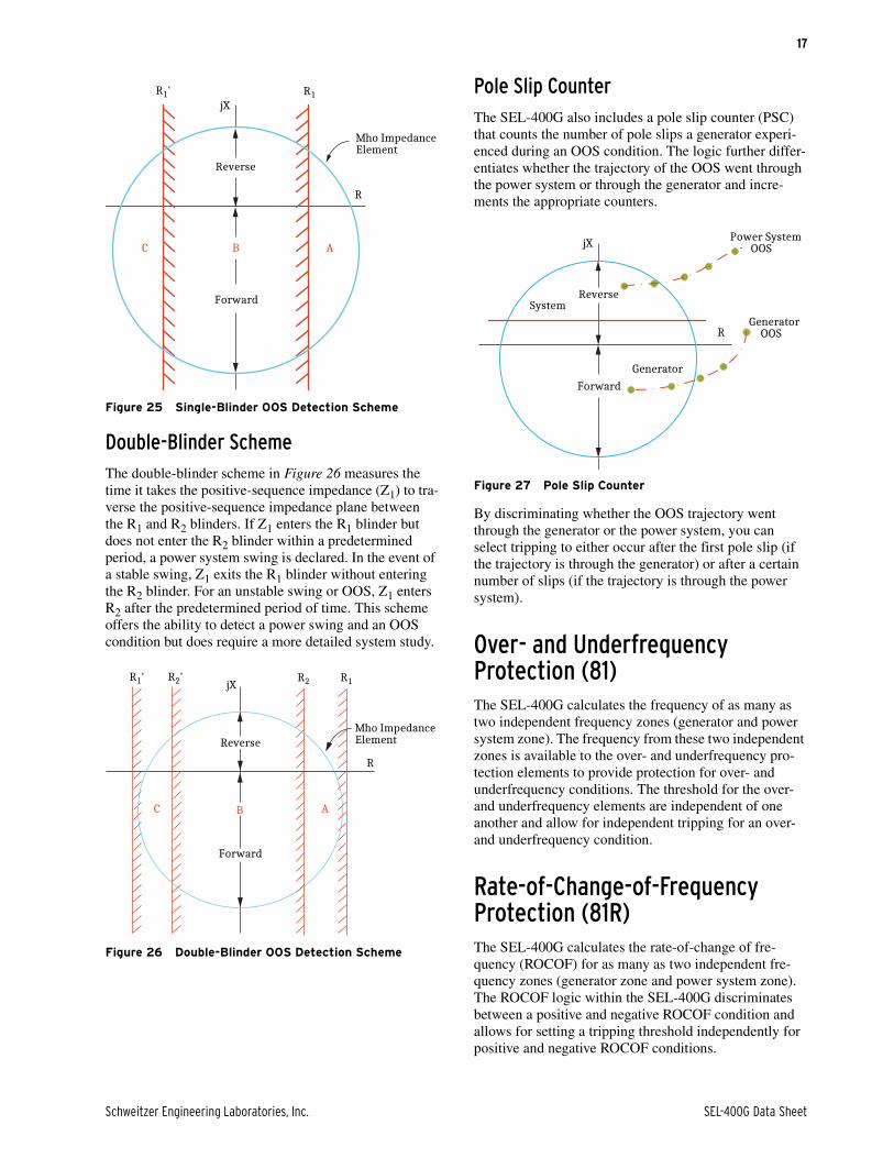
➤ Out-of-Step Protection (78). The SEL-400G provides two out-of-step (OOS) protection schemes: single or double blinder. The SEL-400G also includes a pole slip counter (PSC) that counts the number of pole slips a generator experienced during an OOS condition.
➤ Over- and Underfrequency Protection (81). The SEL-400G provides six levels of over- or underfrequency protection with undervoltage supervision. The protection can be configured for two independent frequency zones (generator and power system zone).
➤ Rate-of-Change-of-Frequency Protection (81R). The SEL-400G provides six levels of over- or under-rate-of change-of-frequency protection with undervoltage supervision. The protection can be configured for two independent frequency zones (generator and power system zone).
➤ Frequency Accumulation Protection (81A). The SEL-400G provides frequency accumulation protection by measuring the time-of-operation in as many as eight frequency bands. The relay also supports continuous bands.
➤ Thermal Overload Protection (49). The SEL-400G provides three independent general-purpose thermal elements that conform to IEC 60255-149 standard.
➤ Breaker Failure Protection (50BF). The SEL-400G provides high-speed breaker failure for as many as four circuit breakers. The logic is immune to subsidence current and complimented with breaker flashover detection logic.
➤ System Backup Protection. The SEL-400G provides phase distance (21P) elements, voltage-controlled time-overcurrent (51C) elements, and voltage-restrained time-overcurrent (51V) elements for system backup protection.
➤ Synchronism Check (25). The SEL-400G provides a synchronism-check function for as many as three breakers. The function provides supervision for acceptable voltage window and maximum percentage difference, maximum and minimum allowable slip frequency, target closing angle, and breaker closing delay.
➤ Autosynchronizer (25A). The SEL-400G provides comprehensive automatic synchronization control of governor and voltage regulators for as many as three breakers through use of pulse width modulated contact outputs.
➤ Loss of Potential (60). The SEL-400G provides loss-of-potential (LOP) elements for the V and Z terminals.
SEL-400G Data Sheet Schweitzer Engineering Laboratories, Inc.
4
➤ Synchrophasors. The SEL-400G provides synchrophasor measurement of all 18 currents and 6 voltage channels. The relay complies with IEEE C37.118.1/2-2011, -2104a Standard for Synchrophasor Measurements for Power Systems and supports as many as five unique synchrophasor data streams via serial or Ethernet communications ports. The relay can record Synchrophasor data for as long as 180 seconds based on user-settable triggers.
➤ Digital Relay-to-Relay Communications. Use MIRRORED BITS® communications to monitor internal element conditions among relays within a station, or among stations, by using SEL fiber-optic transceivers. Send digital, analog, and virtual terminal data over the same MIRRORED BITS channel. Receive synchrophasor data from as many as two other devices transmitting IEEE C37.118 format synchrophasors at rates as fast as 60 messages per second.
➤ Automation. Take advantage of enhanced automation features that include programmable elements for local control, remote control, protection latching, and automation latching.
➤ Comprehensive Metering. Use full metering capabilities of the SEL-400G that include fundamental, rms, maximum/minimum, demand/peak, energy, station battery, temperature, and synchrophasor.
➤ Breaker and Battery Monitoring. The SEL-400G provides breaker monitoring for as many as four breakers. It records electrical and mechanical operating times for both the last operation and the average of operations since function reset. Battery monitoring provides notification of substation battery voltage problems using voltage dip detection during trip or close operations.
➤ Comprehensive Temperature Monitoring. When the SEL-400G is used in conjunction with the SEL-2600 RTD Module and/or SEL-2411 Programmable Automation Controller, as many as 24 temperature measurements over serial and 24 over Ethernet are available. Each can be programmed for two levels of thermal protection per element.
➤ Ethernet Access. Access all relay functions with the optional Ethernet card. Use IEC 61850, Modbus TCP, or DNP3 protocol directly to interconnect with automation systems. Use File Transfer Protocol (FTP) for high-speed data collection. Connect to substation or corporate LANs to transmit synchrophasors in the IEEE C37.118.1/2-2011, -2104a format, using TCP or UDP internet protocols.
➤ Oscillography. The SEL-400G provides high-resolution events that record unfiltered voltages and currents at sampling rates as high as 8 kHz with time-stamp accuracy of one microsecond. The SEL-400G also provides low-resolution events that record filtered voltages, currents, and other processed analogs and digitals at 400 Hz for as long as 24 seconds. The SEL-400G also provides integrated disturbance recorder that can record 20 analog and 800 digital channels at 50 Hz for as long as 300 seconds.
➤ Sequential Events Recorder (SER). Record the last 1000 entries, including setting changes, relay start-up, password access, and as many as 250 selectable logic elements.
➤ Rules-Based Settings Editor. Use an ASCII terminal to communicate and set the relay, or use the PC-based Grid Configurator software to configure the SEL-400G, view a replica of the relay front-panel HMI, analyze fault records with relay element response, and view real-time phasors and harmonic levels.

Schweitzer Engineering Laboratories, Inc. SEL-400G Data Sheet
5
SEL-400G Relay ApplicationsSteam Turbine Generator
Hydro Turbine Generator
Figure 2 Steam Turbine Generator
V2 X Z S V1UT V3
25
Y1W
SEL-400G
REF1
GSU
G
SEL-2664SEL-2664S
25REF
87T
64F
64S
64G
87G 50BF50BF
49 4678403221
81592724
Figure 3 Hydro Turbine Generator
W Y
G
V2 SZ V1, V3T
SEL-400G
BRAKE AUXTXFR
UX
INAD
25A50BF87
64G
81592724
21 46 49784032
50
51
50
51
SEL-2664SEL-2664S
64F
64S
87

SEL-400G Data Sheet Schweitzer Engineering Laboratories, Inc.
6
Combustion Gas Turbine Generator
Protection FeaturesUniversal Differential Element (87)The SEL-400G universal differential element provides current differential protection for either a generator or a transformer.
Alternatively, the SEL-400G can provide lateral differen-tial protection and transverse differential protection for the overall generator.
The current differential element is implemented as a per-centage restraint differential element with an adaptive slope. The slope of the percentage restraint differential element is controlled by the external fault detector (EFD). This allows the element to provide sensitivity for internal faults and at the same time provide security for external faults that can lead to CT saturation. Figure 7 shows how the EFD adjusts the slope of the percentage restraint differential element.
Figure 4 Combustion Gas Turbine Generator
LCI
START
X S TY1W
SEL-400G
Z
GSU
U V1, V3
81592724
49 46 87G
25A
78403221
50BF REF 50BF
V2
SEL-2664SEL-2664S
64F
64S
64G
G
Figure 5 Two Universal Differential Elements (87) Enable Differential Protection for Both the Generator and the GSU
Generator GSU
87 Zone 187 Zone 2
SEL-400G
Figure 6 SEL-400G Provides Both Lateral Differential Protection and Transverse Differential Protection
Generator GSU
87 Zone 1
87 Zone 2
SEL-400G
TransverseDifferential
LateralDifferential

Schweitzer Engineering Laboratories, Inc. SEL-400G Data Sheet
7
The EFD switches the differential element to a more secure slope setting if one of the two following condi-tions is detected.
AC External Fault DetectorWhen a high-current fault external to the zone of protec-tion occurs, one of the zone differential CTs can saturate very quickly (less than 1 cycle), which means that the CT will not accurately replicate the primary current and introduce errors into the differential calculation. Typi-cally, during CT saturation, the operate current (IOP) increases and the restraint current (IRST) decreases, which challenges the security of the differential element. The ac external fault detector detects this external fault condition by comparing the incremental change in oper-ating current against the incremental change if the restraint current. See Figure 8.
If the logic detects an incremental change in the restraint current (IRT) without an incremental change in the operating current (IOP) within 1/8th of a power system cycle, the logic declares and external fault condition. When an external fault condition is declared the slope of the percentage differential element is increased to help secure the differential element during this external fault conditions.
High DC Phase Current Detection LogicLong lasting dc offsets such as those caused by trans-former energization, line reactor energization, or slow clearing faults on power systems with a high X/R ratio can cause saturation of one of the zone differential CTs. The large dc component in the phase current results in slow saturation of the CT. If this condition goes unde-
Figure 7 Dynamically Adaptive Differential Slopes in Response to Internal and External Fault
Restrain
Operate
IOP
Operate
Restrain
IRST(a)
IOP
IRST(b)
Figure 8 External AC Fault Detector Logic
12
k
ABS
ABSIOP
1-cyclebuffer
1/8cyc
0
�
IRST
THR
�IOP�IOP
�IRSTExternal
�IRSTInternal
EFDDC
EFDAC EFD
1-cyclebuffer
�

SEL-400G Data Sheet Schweitzer Engineering Laboratories, Inc.
8
tected, the security of the differential element will be challenged. The high dc phase current detector logic in the SEL-400G detects this condition using the logic shown in Figure 9.
The high dc phase current logic consists of two parts. The first part verifies that there is no fault present within the differential zone of protection by verifying that the operating current (IOP) is below a fraction of the restrained current (IRST). The second part of the logic verifies that the dc component (IDC) of the phase cur-rent is of sufficient magnitude and of a high enough ratio.
If both parts of the logic are satisfied, the logic declares a high dc phase current (EFDDC) and switches the differ-ential element into high security mode.
Stator Winding Ground Fault Protection (64G/64S)The SEL-400G offers both passive and active methods for detecting ground faults across 100 percent of the sta-tor winding without sacrificing security. Generator stator winding ground faults are the predominant generator faults. Because of the grounding of the generator, the magnitude of the fault current is low (typically 5–15 A), therefore, detecting these faults is generally a tradeoff between security and dependability.
➤ Passive Stator Ground Fault Protection. Neutral terminal fundamental overvoltage protection (64G1) protects approximately 5 to 100 percent of the stator winding. Third-harmonic differential voltage protection (64G2) or third-harmonic voltage ratio protection (64G3) provide protection of the stator winding from the neutral terminal to approximately 35 percent of the stator winding. Therefore, enabling the 64G1 and 64G2 or 64G3 affords protection for 100 percent of the stator winding without sacrificing security.
➤ Active Stator Ground Fault Protection. Injecting a current signal into the stator winding provides protection for 100 percent of the stator winding. The SEL-400G, in conjunction with the SEL-2664S Stator Ground Protection Relay, provides 100 percent dependable and secure stator winding protection. When the SEL-2664S is used
in conjunction with the SEL-400G, it is possible to monitor the stator winding insulation resistance and capacitance to ground. This allows for the early detection of stator winding insulation failure. The major advantage of using an active stator ground fault detection method is that a stator winding ground fault can be detected when the generator is at standstill.
Most stator winding ground faults begin as arcing (inter-mittent) ground faults. The SEL-400G stator winding ground fault protection element includes an integrating timer that is specifically designed to detect intermittent ground faults and isolate the generator before the fault evolves into a permanent fault. Detecting a stator wind-ing ground fault while the fault is still in the intermittent stage allows the damage to the generator to be contained.
In high-impedance grounded generators, stator ground faults in the upper 90 percent of the stator winding are detected by the 64G1 element, which measures the fun-damental neutral voltage (59N) across the neutral grounding resistor of the generator. Because of the effect of the GSU interwinding capacitance, the fundamental neutral overvoltage threshold cannot be set below 10 per-cent of the generator terminal voltage; therefore, stator ground faults in the lower 10 percent of the stator wind-ing (near the generator neutral) cannot be detected by the 64G1 element. To detect stator winding ground faults in the lower 10 percent of the stator winding, the third-har-monic voltages measured at the neutral and terminal of the generator are used (64G2/3). The SEL-400G offers two elements, 64G2 and 64G3, to detect ground faults in the lower 10 percent of the stator winding. The 64G2 and 64G3 elements use the fact that the ratio of the third-har-monic voltage at the terminals of the generator and the neutral of the generator under a nonfaulted condition is approximately constant. When the generator experiences a stator winding ground fault near the generator or neu-tral terminals, this ratio is disrupted, and the elements declare a stator winding ground fault. Therefore, as seen in Figure 10, combining the 64G1 and the 64G2 or 64G3 elements provide 100 percent protection for stator wind-ing ground faults.
Figure 9 High DC Phase Current Detector Logic
3cyc 1
cyc
ABSKOP
IOP�
� = A, B, C
IRST�
KDCI�MAG
I�DC
IPUDCEFDDC
Figure 10 Combine the 64G1 and Either the 64G2 or 64G3 Element to Provide 100 Percent Protection for Stator Ground Faults
NG
R
GeneratorTerminals
Stat
or W
indi
ng
GeneratorNeutral
59N
64G1(= 90%)
64G2/3(= 15%)

Schweitzer Engineering Laboratories, Inc. SEL-400G Data Sheet
9
The SEL-400G also interfaces with the SEL-2664S, a stator ground protection relay. The SEL-2664S is capable of not only detecting stator winding ground faults but also monitoring the neutral grounding resistor (NGR). The SEL-2264S uses current injection to detect stator ground faults and can be applied as follows:
➤ Injecting current via the neutral generator resistor (NGR) when the NGR is located on the secondary side of the neutral grounding transformer (NGT), as shown in Figure 11(a).
➤ Injecting current via the tap of the NGR with the NGR located on the secondary side of the NGT, as shown in Figure 11(b).
➤ Injecting current via the secondary winding of a voltage transformer (VT) when the NGR is the primary of the generator neutral, as shown in Figure 11(c).
➤ Injecting current via the tap of the NGR with the NGR located across the broken delta winding of the NGT this is typically the case when the neutral point of the generator is not earthed, as shown in Figure 11(d).
When the SEL-400G is interfaced with the SEL-2664S, both devices can provide 100 percent stator ground fault protection independent of one another. The added benefit of using the SEL-2664S in conjunction with the SEL-400G is that the SEL-400G can record and trend the measured stator winding resistance and capacitance over time.
Figure 11 Application Examples of Using SEL-2664S for 100 Percent Stator Ground Fault Protection
NG
R
NGT
SEL-2664S
(a)Injecting current via NGR
NG
R
NGT
SEL-2664S
(b)Injecting current via secondary winding of
VT when NGR is within neutral of generator
NG
R
NGT
SEL-2664S
(d)Injecting current via broken-delta winding of VT
NG
R
SEL-2664S
(c)Injecting current via broken-delta winding of NGT
VT
Figure 12 Stator Winding Insulation Resistance and Capacitance for 24 Hours
12 a.m.0
20
40
60
Res
ista
nce
(kΩ
)
2 a.m. 4 a.m. 6 a.m. 8 a.m. 10 a.m. 12 p.m. 2 p.m. 12 a.m.4 p.m. 6 p.m. 8 p.m. 10 p.m.0
1
2
3
Cap
acit
ance
(μF
)
t: 1:55 a.m.C: 1.77 μF
t: 1:55 a.m.
R: 51 k Ω
t: 10:55 p.m.R: 1.2 k Ω
t: 10:55 p.m.C: 2.7 μF
t: 11:00 a.m.R: 35 k Ω
t: 11:00 a.m.C: 2 μF
t: 2:00 a.m.C: 2.75 μF
t: 2:00 a.m.R: 1.2 k Ω

SEL-400G Data Sheet Schweitzer Engineering Laboratories, Inc.
10
Field Ground Fault Protection (64F)The first field winding-to-ground fault generally does not impact the performance of the generator. However, the second ground fault will short out part of the field wind-ing. The field current in a large generator is considerable, and shorting out part of the field winding will divert a large part of the current and can damage the winding conductor very rapidly. Shorting out part of the field winding will create a non-symmetrical flux distribution in the generator, as shown in Figure 13(b). This non-symmetrical flux distribution results in a non-symmetri-cal (unbalance) force within the generator
This unbalanced force rotates within the generator and can result in severe vibration (depending on the location of the second ground fault) within the generator. There-fore, it is important to detect the first field-winding-to-ground fault.
The SEL-2664 injects a low-frequency square wave volt-age into the field winding of the generator and calculates the insulation resistance of the field winding. The field winding insulation resistance measured by the SEL-2664 is consumed by the field winding ground detection ele-ment (64F) in the SEL-400G. The 64F element can be configured to provide either an alarm or trip functions for the first field-winding-to-ground fault.
The SEL-400G also provides the user with the option to trend the field winding insulation resistance, allowing the user to predict when the field winding insulation resis-tance will reach a minimum allowable value and take the appropriate action before the generator incurs serious damage.
The SEL-400G provides rotor ground fault protection when paired with the SEL-2664. The SEL-2664 calcu-lates the insulation resistance of the generator field wind-ing to ground and transmits these data to the SEL-400G. The SEL-2664 can perform the insulation resistance cal-
culation with the generator either offline or online. The SEL-2664 is connected in parallel with the exciter to the generator field winding, as shown in Figure 14.
The equivalent circuit of the SEL-2664 and the generator rotor field is as shown in Figure 15(a). The SEL-2664 applies a pulsating voltage (VINJECT) to the generator field and measures the magnitude of the voltage drop across an internal resistor to ground (R), as shown in Figure 15(b). When the rotor insulation is normal or healthy, the major portion (>95 percent) of the injected voltage is dropped across the rotor insulation (VROT_INS) and very little voltage is dropped across the resistor inter-nal (VR) to the SEL-2664, Figure 15(c). When the rotor field experience a ground fault, the major portion of the injected voltage is dropped across the internal resistor, as shown in Figure 15(d).
Figure 13 Flux Distribution (Symmetrical) in a Healthy Generator (a) and Flux Distribution (Non-Symmetrical) in a Generator With a Double-Rotor Ground Fault (b)
N
S
(a)
N
S
(b)
Figure 14 SEL-2664 Connected in Parallel With Generator Field Winding Exciter
Figure 15 SEL-2664 Circuit Diagram (a); Injected Voltage and Current (b–d)
SEL-2664S
Exciter+ -
(b)
(c)
(d)
VNEG
VPOS
VIN
JECT
VIN
JECT
VR
VR
VR
Time (s)
R
RINSCINS
VR
OT
_IN
S
Rotor
VGEN_INS
(a)
0 2 4 6 8 10

Schweitzer Engineering Laboratories, Inc. SEL-400G Data Sheet
11
REFThe SEL-400G provides comprehensive protection for the GSU and includes a REF element to provide protec-tion for ground faults on the GSU high-voltage winding close to the neutral point. The REF element can also be used to provide selective ground fault protection in appli-cations where several low-impedance grounded genera-tors share a common bus.
Stator Winding Turn-to-Turn Fault Detection (60P/60N/59)Detection of a turn-to-turn fault is impossible using stan-dard or conventional protection elements. Therefore, the SEL-400G includes several advanced protection ele-ments for this purpose. The fault current developed in the shorted turn during a turn-to-turn fault is of such a large magnitude that it creates the possibility of a fire hazard. However, at the terminals of the generator where the dif-ferential current CTs are located, no differential current is generated, i.e., the current flowing into the faulted winding equals the current flowing out of the faulted winding. Therefore standard or conventional protection elements cannot be applied.
In multiwinding generator units, such as those typically used in hydro applications, split-phase protection is employed to detect turn-to-turn faults. This method requires many dedicated CTs, especially if the machine has multiple branches per phase. For single-branch gen-erator units, such as those typically found in steam plants, the zero-sequence voltage overvoltage method is employed. The SEL-400G provides several protection elements to detects stator winding turn-to-turn faults.
Adaptive Split-Phase ProtectionThe split-phase protection elements (60P and 60N) in the SEL-400G provides sensitive turn-to-turn fault protec-tion in a multibranch generator. The 60P element can be applied in the traditional split-phase configuration between winding branches, as shown in Figure 16(a), and the 60N element can be applied if measuring the neutral current in a multibranch generator with multiple neutral terminals, as shown in Figure 16(b).
To not compromise security for sensitivity, the split-phase element has an adaptive threshold that adjusts for non-fault changing system conditions (seasonal changes or changes because of a winding repair, etc.). Should the external fault detector element detect a fault external to the generator differential zone, it sends a signal to the split-phase element for added security.
Zero-Sequence Voltage Stator Overvoltage ElementThe 60P/60N elements work well for detecting turn-to-turn faults in a generator where a phase is made up of multiple branches. This method cannot be used when only a single branch makes up a phase in the generator.
The zero-sequence impedance (Z0) of a generator is very small (almost negligible) when compared to the positive-sequence impedance (Z1). Therefore, the zero-sequence voltage drop (V0) across the generator winding under normal operating conditions, stator winding ground faults, and external faults is negligible. However, should the generator develop a winding turn-to-turn fault, the voltage across that winding is reduced, which results in zero-sequence voltage developing in the generator stator winding. This zero-sequence voltage difference can be measured directly using the one of the two methods shown in Figure 17. The method shown in Figure 17(a) provides greater sensitivity. The method shown Figure 17(b) is simpler to apply because it does not require an HV cable but it does require that both VTs have the same ratio. This logic can be realized in the SEL-400G by using SELOGIC.
Figure 16 Traditional Split-Phase Protection for Detecting Stator Turn-to-Turn Fault (a), Using the Inter-Neutral CT to Detect a Stator Turn-to-Turn Fault (b)
SEL-400G
60P
Split-Phase CTs
SEL-400G
60N
Inter-Neutral CT
(a) (b)

SEL-400G Data Sheet Schweitzer Engineering Laboratories, Inc.
12
Irrespective of the method used to obtain the zero-sequence voltage across the generator, connect the volt-age input to one of the V-terminal voltage channels and configure an overvoltage element (59) to provide turn-to-turn protection for the generator.
Pumped Storage Logic A pumped storage machine can operate either as a motor or a generator. Traditional protection philosophy has required external CT/PT switching or the use of separate relays, one to protect during motoring operation and one to protect during generator operation. The SEL-400G internally corrects the phasing introduced by the revers-ing switch. The logic ensures that the phasing of the dif-ferential element is correct and that the phase rotation is correct. This allows a pumped storage hydro unit to be protected with a single SEL-400G without the need to externally switch the CT or PT secondary wiring.
Extended Range Frequency Tracking of 5–120 Hz Generators may, at times, operate at frequencies signifi-cantly different than nominal. For example, hydro gener-ators may overspeed by as much as 50 percent when rejected from the system. A hydro generator may be rejected on its own or as one of a group of machines. Conversely, large combustion gas turbines (CGTs) com-monly employ static starting. During starting, the machine operates as a synchronous motor driven by a load commutated inverter (LCI). The excitation is varied to maintain a nominal V/Hz which, in turn, affects the terminal voltage. Total start time can be as long as 30 minutes. During this time, the frequency may be at or less than 20 Hz for an extended period. Similarly, pumped storage hydro and cross-compound steam tur-bines can operate at low frequency with field applied. The SEL-400G wide-range frequency tracking algorithm ensures that all protection functions are secure and dependable regardless of the system frequency. The SEL-400G also independently tracks the generator and system frequencies.
Loss-of-Field Protection (40)The SEL-400G offers two impedance-based loss-of-field (LOF) schemes and a capability based LOF scheme, to protect the generator during a LOF event. When a gener-ators field current is reduced there is a reduction in the generators interval voltage (EI) and a reduction of the magnetic coupling between the generator stator and rotor.
Reducing the generator EI reduces the reactive power (VAR) output of the generator and can result in the gen-erator absorbing VARs from the power system. For a complete LOF condition, the VARs absorbed by the gen-erator can be as high as two times the generator MVA rating. In a salient pole generator, a total LOF condition will result in the stator windings being overloaded.
Figure 17 Using Zero-Sequence Voltage Overvoltage to Detect a Stator Turn-to-Turn in a Single-Branch Generator
GeneratorGSU
VTHV cable
(a)
GeneratorGSU
VT
SEL-400G
59V0
(b)
VV
SEL-400G
59V0
VV
Figure 18 Single SEL-400G to Protect During Both Generating and Motoring Operation for Pumped Storage Application
Generator/Motor
G
M
GSUCB
87G21P
SEL-400G
87T

Schweitzer Engineering Laboratories, Inc. SEL-400G Data Sheet
13
In a cylindrical rotor generator, the stator end core heat-ing is the limiting factor. When the field current is reduced in a cylindrical rotor generator, the rotor end iron transitions from being saturated to being unsatu-rated. The transition of the rotor end iron from the satu-rated region to the unsaturated region reduces the reluctance path between the stator end core and rotor end iron. When the reluctance path between the stator end core and rotor end iron decreases, the flow of flux (leak-age flux/fringe flux) between them is increased, as shown in Figure 19. The increase in flux flow between the stator end core and the rotor end core results in increased stator end core heating.
Reducing the magnetic coupling between the generator stator and the rotor reduces the ability of the stator and rotor to remain in synchronism. If this coupling is weak-ened sufficiently, the generator will lose synchronism and the generator will transition from a synchronous to induction operation requiring an increase in rotor speed (r > sync). Steam turbines generally have a low toler-ance to overspeed. The resulting slip also induces cur-rents into damper bars and rotor body. This can lead to overheating of the rotor and possible damage if the slip is high.
The SEL-400G offers an impedance-based LOF scheme and a PQ-based LOF scheme, to protect the generator during a LOF.
Impedance-Based LOF ElementsThe SEL-400G offers an impedance-based LOF element that can be configured for either of the two following schemes:
Negative-Offset Zone 2 Scheme
The negative offset scheme is comprised of two mho ele-ments. The inner element (Zone 1) provides protection for a loaded generator (30 to 100 percent) and is coordi-nated so that an unstable swing does not enter Zone 1. Zone 1 is set with a minimum delay.
Zone 2 is meant to detect a LOF for a lightly loaded machine. Its greater coverage makes it more likely to pick up during a stable swing. Therefore, this zone requires a longer delay setting.
Positive-Offset Zone 2 Scheme
This scheme is also known as a qualified trip scheme and is supervised by an undervoltage (UV) and directional element. This scheme determines a LOF condition if the impedance locus enters the mho characteristic and is lower than the directional element. In a weak power sys-tem, the system voltage collapses, and the scheme oper-ating time accelerates. In a strong power system, the operator has time to correct the situation.
Figure 19 Flow of Leakage Flux (Fringe Flux) When the Rotor Retaining Ring Comes Out of Saturation
Fan RotorRetaining Ring
Leakage Flux(Red)
Useful Flux(Blue)
Figure 20 Negative-Offset Zone 2 Scheme
Figure 21 Positive-Offset Zone 2 Scheme
jX
R
Xd’/2
1 pu
Xd
Zone 1
Zone 2
jX
RXd’/2
XT = XSYSTEM+ XXMFR
XT
Z2 = 1.1 ��Xd + XT Z1 =1 pu
Z1
Z2
DIR
SEL-400G Data Sheet Schweitzer Engineering Laboratories, Inc.
14
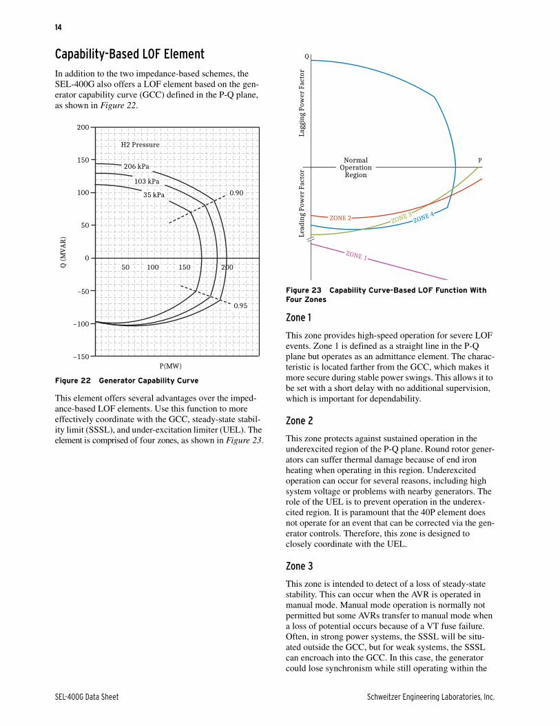
Capability-Based LOF ElementIn addition to the two impedance-based schemes, the SEL-400G also offers a LOF element based on the gen-erator capability curve (GCC) defined in the P-Q plane, as shown in Figure 22.
This element offers several advantages over the imped-ance-based LOF elements. Use this function to more effectively coordinate with the GCC, steady-state stabil-ity limit (SSSL), and under-excitation limiter (UEL). The element is comprised of four zones, as shown in Figure 23.
Zone 1
This zone provides high-speed operation for severe LOF events. Zone 1 is defined as a straight line in the P-Q plane but operates as an admittance element. The charac-teristic is located farther from the GCC, which makes it more secure during stable power swings. This allows it to be set with a short delay with no additional supervision, which is important for dependability.
Zone 2
This zone protects against sustained operation in the underexcited region of the P-Q plane. Round rotor gener-ators can suffer thermal damage because of end iron heating when operating in this region. Underexcited operation can occur for several reasons, including high system voltage or problems with nearby generators. The role of the UEL is to prevent operation in the underex-cited region. It is paramount that the 40P element does not operate for an event that can be corrected via the gen-erator controls. Therefore, this zone is designed to closely coordinate with the UEL.
Zone 3
This zone is intended to detect of a loss of steady-state stability. This can occur when the AVR is operated in manual mode. Manual mode operation is normally not permitted but some AVRs transfer to manual mode when a loss of potential occurs because of a VT fuse failure. Often, in strong power systems, the SSSL will be situ-ated outside the GCC, but for weak systems, the SSSL can encroach into the GCC. In this case, the generator could lose synchronism while still operating within the
Figure 22 Generator Capability Curve
0
50
100
150
200
Q (
MV
AR
)
–150
–100
–50
P(MW)
20015010050
H2 Pressure
0.95
206 kPa
103 kPa
35 kPa 0.90
Figure 23 Capability Curve-Based LOF Function With Four Zones
Q
P
ZONE 1
Lagg
ing
Pow
er F
acto
rLe
adin
g Po
wer
Fac
tor
NormalOperation
Region
ZONE 3ZONE 4ZONE 2

Schweitzer Engineering Laboratories, Inc. SEL-400G Data Sheet
15
GCC. The 40P Zone 3 element is intended to detect this occurrence. The characteristic requires only two settings: the equivalent system impedance (XS) and the steady-state direct axis impedance (Xd). Because Zone 3 repli-cates the SSSL, it is static in the impedance plane. If studies show that the SSSL cannot intrude into the GCC (because of a strong system), or if the excitation system does not allow the possibility of operating in manual mode (because of design redundancies), you can disable Zone 3. Zone 3 can be supervised by an input from the AVR when the AVR transitions to manual mode.
Zone 4
This zone is intended to provide an alarm when the gen-erator is operated outside of the GCC. The GCC can be divided into three segments: the upper segment, which is the field current limited; the right segment, which is sta-tor current limited; and the lower segment, which is the underexcitation limit. Each segment is represented by a curve fitted to three pairs of PQ coordinates. Because the segments intersect, a total of seven PQ coordinates define this characteristic. This segment can also contract or expand dynamically by using a signal representing the cooling capability of the generator (for example, hydro-gen pressure).
Current Unbalance Protection (46)Fundamental negative-sequence current in the stator winding of the generator induces a double-frequency current in the generator amortisseur (damper) windings, resulting in rapid overheating. The negative-sequence definitive-time element provides an early-stage warning alarm for an unbalance system operating condition, and, should the condition persist, the inverse time-overcurrent element provides tripping to prevent damage to the gen-erator rotor.
Unlike other generator protection relays, the SEL-400G current unbalance element measures the harmonic cur-rents in the rotor in compliance with the IEEE C50.12 and IEEE C50.13 thermal model. As specified by IEEE C50.12, the 46 element in the SEL-400G scales each harmonic order by a weighting factor determined by the harmonics sequence and frequency to account for skin effect, as shown in Equation 1.
Equation 1
By correctly accounting for the harmonic currents, the SEL-400G 46 element affords greater thermal protection to the generator rotor and amortisseur windings.
Geomagnetically induced currents (GIC) can cause the core of the GSU to become saturated, which results in the GSU drawing non-sinusoidal currents rich in har-monics. These harmonic currents do not negatively impact the GSU but do contribute to the heating of the amortisseur winding in the generator rotor. Correctly accounting for the harmonic currents provides better pro-tection of the generator rotor and amortisseur winding during a GIC event.
Overexcitation Protection (24)For a generator or transformer to generate or transfer power, a mutual magnetic field (flux) must be created. The strength of the magnetic field determines the amount of power that can be generated or transferred. In general, the maximum power transfer of the generator or trans-former determines the maximum magnetic field (flux) of the generator or transformer. The generator stator core, as well as the transformer core, have a maximum flux density (flux per unit area) they can support. A flux den-sity above the design limit results in the generator or transformer operating in the saturation region and results in heating of the stator or transformer core above its design limits. Operating a generator or transformer in the saturation region for an extended period damages the generator stator or transformer core.
The SEL-400G provides volts-per-hertz (V/Hz) elements to provide protection for overfluxing. The V/Hz elements calculate the ratio of the normalized voltage (V) to the normalized frequency (f). This ratio (Equation 2) is pro-portional to the flux () in the generator stator or trans-former core if the voltage is perfectly sinusoidal.
Equation 2
The V/Hz element provides two levels of definitive-time V/Hz protection. Two user-defined inverse time curves are also available.
Inadvertent Energization (INAD)When voltage is applied to the generator terminals with-out the rotor field winding being energized, the generator behaves like an induction motor being started directly online. Similarly to the induction motor, the generator draws current several times the rated current of the gen-erator for a prolonged period until the rotor comes close to synchronous speed. During the rotor acceleration period, currents are induced into the rotor circuit, result-ing in excessive heating of the rotor, which can result in damage. The SEL-400G provides an inadvertent energi-zation logic that arms itself when the generator is taken offline. If the generator is energized inadvertently, the logic detects this condition and takes the appropriate
I2eq I22 n 1+
2------------ in22 n 1–
2------------ in12
+ , n
n+ 2 ... 15= =
Vf---- k=

SEL-400G Data Sheet Schweitzer Engineering Laboratories, Inc.
16
action. Rather than providing a single element at the gen-erator neutral, the SEL-400G provides an element for each breaker. This allows the element to be applied in applications that employ static starting or dynamic brak-ing.
Directional Power Protection (32)When the prime mover of a generator is lost, the mechan-ical power input to the generator decreases to zero and the generator transitions from generating to motoring mode. This transition has no negative impact on the gen-erator, but it does negatively impact the prime movers. In steam turbines, normal steam flow removes heat from the turbine blades and other turbine parts. In motoring mode, there is insufficient steam flow for cooling. The resultant temperature buildup causes the turbine blades, especially the low-pressure turbine blades, to be annealed or dis-torted. In gas turbines, the drive gear is generally designed for unidirectional operation i.e., the prime mover driving the generator. Should the generator drive the prime mover, the drive gear will experience excessive wear.
In motoring mode, the power the generator draws from the power system is dependent on the prime mover; hydro turbines with their turbine blades above the tail race water level and steam turbine that are under vacuum will draw between 0.2–3 percent of their rated power. Therefore, to detect that a generator is in motoring mode, a very sensitive power element is required. The SEL-400G provides four instances of sensitive power elements with independent time delays. Additionally, the SEL-400G provides a biased characteristic that ensures both security and dependability for the cases when the generator is exporting a large amount of reactive power and is in motoring, as shown in Figure 24. In these cases, small instrument transformer angle error can negatively impact the sensitive power calculations and jeopardize the security or dependability of the element.
Out-of-Step Protection (78)The SEL-400G provides out-of-step (OOS) protection that can be configured for either of the following two schemes:
Single-Blinder SchemeThe single-blinder scheme (see Figure 25) measures the time it takes the positive-sequence impedance (Z1) to tra-verse the positive-sequence impedance plane to distin-guish between an OOS condition and a power system fault. A power system fault will traverse the positive-sequence impedance plane much more rapidly than an OOS condition. The scheme declares an OOS condition if the time between the positive-sequence impedance entering the mho element and one of the blinders (R1 or R1’) is longer than 1/2 a power system cycle. The scheme will issue an out-of-step trip (OOST) command if the positive-sequence impedance traverses the positive-sequence impedance plane from left to right or vice versa.
Figure 24 Biased Characteristic to Ensure Dependability and/or Security During High Reactive Power but Low Active Power Conditions
BiasedCharacteristic
AngleErrors
Q
P
MotoringWith
SignificantVARs
Schweitzer Engineering Laboratories, Inc. SEL-400G Data Sheet
17
Double-Blinder SchemeThe double-blinder scheme in Figure 26 measures the time it takes the positive-sequence impedance (Z1) to tra-verse the positive-sequence impedance plane between the R1 and R2 blinders. If Z1 enters the R1 blinder but does not enter the R2 blinder within a predetermined period, a power system swing is declared. In the event of a stable swing, Z1 exits the R1 blinder without entering the R2 blinder. For an unstable swing or OOS, Z1 enters R2 after the predetermined period of time. This scheme offers the ability to detect a power swing and an OOS condition but does require a more detailed system study.
Pole Slip CounterThe SEL-400G also includes a pole slip counter (PSC) that counts the number of pole slips a generator experi-enced during an OOS condition. The logic further differ-entiates whether the trajectory of the OOS went through the power system or through the generator and incre-ments the appropriate counters.
By discriminating whether the OOS trajectory went through the generator or the power system, you can select tripping to either occur after the first pole slip (if the trajectory is through the generator) or after a certain number of slips (if the trajectory is through the power system).
Over- and Underfrequency Protection (81)The SEL-400G calculates the frequency of as many as two independent frequency zones (generator and power system zone). The frequency from these two independent zones is available to the over- and underfrequency pro-tection elements to provide protection for over- and underfrequency conditions. The threshold for the over- and underfrequency elements are independent of one another and allow for independent tripping for an over- and underfrequency condition.
Rate-of-Change-of-Frequency Protection (81R)The SEL-400G calculates the rate-of-change of fre-quency (ROCOF) for as many as two independent fre-quency zones (generator zone and power system zone). The ROCOF logic within the SEL-400G discriminates between a positive and negative ROCOF condition and allows for setting a tripping threshold independently for positive and negative ROCOF conditions.
Figure 25 Single-Blinder OOS Detection Scheme
Figure 26 Double-Blinder OOS Detection Scheme
Forward
Reverse
R1R1'
Mho Impedance Element
ABC
jX
R
Forward
Reverse
R1R2R1' R2'
Mho Impedance Element
ABC
jX
R
Figure 27 Pole Slip Counter
Forward
Reverse
jX
R
Generator
System
Power System OOS
Generator OOS

SEL-400G Data Sheet Schweitzer Engineering Laboratories, Inc.
18
Frequency Accumulation Protection (81A)The turbine blades of a generator prime mover are designed to operate within a very narrow band around the nominal frequency of the generator. If the turbine speed fall outside this nominal band, it can excite fre-quencies that coincide with the natural frequency of the turbine blades. If this occurs, the turbine blades are exposed to vibration stress well above their design limits, resulting in fatigue of the turbine blades. Turbine blade fatigue is cumulative and non-reversible; therefore, tur-bine manufacturers provide maximum time limits that the turbine can be operated for frequency outside of the nominal frequency, as shown in Figure 28.
The SEL-400G provides frequency accumulation ele-ments that enable the user to configure the frequency bands according to the generator turbine specification. The element accumulates the total duration the turbine blades were exposed to frequencies within the band. If the accumulated time exceed the predefined value, the element generates an output that can be used for alarm purposes.
Thermal Overload Protection (49)Operating a generator beyond its rated capacity (outside its thermal capability) for an extended period leads to damage to the generator in the form of stator and rotor winding insulation degradation. The greatest heat gener-ated during normal generator operation is by the resistive losses in the stator and rotor windings (copper losses). The SEL-400G can use the combined positive (I1) and
negative (I2) current ( ) or the rms current. It can also use the measured ambient temperature to calculate the thermal capacity in the generator and the time before the generator exceeds its thermal capability limit. The measured ambient temperature is obtained from either an
SEL-2600 series RTD module or an SEL-2411 control-ler. The SEL-400G support three general-purpose ther-mal models that conform with the IEC 60255-149 standard.
Breaker Failure Protection (50BF)The SEL-400G provides high-speed breaker failure for as many as four circuit breakers. Breaker failure is initi-ated via a user-defined condition and is qualified by either phase current or residual current, if so selected. The breaker failure logic is supervised by a high-speed open-phase detection logic that is immune to subsidence current that may be present after fault clearing. The breaker failure logic is complimented with breaker flash-over detection logic to protect the generator and genera-tor breaker from a flashover just prior to synchronization.
System Backup Protection (21P/51C/51V/27/59) Distance Protection ElementsThe SEL-400G provides two zones of offset mho phase distance protection to provide backup protection of the generator. Zone 1 is typically set to provide backup pro-tection for bus faults and breaker failures, and to coordi-nate with Zone 1 of the line protection relay; therefore, Zone 1 is typically set with a short reach and a short time delay. Zone 2 is coordinate with the Zone 2 of the line protection; therefore, Zone 2 is typically set with a lon-ger reach and a greater time delay.
Figure 28 Time Restrictions for Safe Turbine Operation at Different Frequency Bands
Time (min)
50
51
52
49
48
47
460.050.001 0.1 0.5 1.0 5.0 10.0 50.0
Continuous Operation
Restricted Operating Time
Restricted Operating Time
Prohibited Operation
Prohibited Operation
Freq
uen
cy (
Hz)
0.005 0.01 100.0
I12 I2
2+
Figure 29 Two Zones of Offset Mho Phase Distance to Provide Backup Protection
Generator
GSU
SEL-400G
21 P
R
jX
21P1
21P2
21OFF

Schweitzer Engineering Laboratories, Inc. SEL-400G Data Sheet
19
Voltage-Controlled Overcurrent ElementsUnder a sustained three-phase fault condition, the gener-ators impedance increases from Xd'' (0.25 pu) to Xd (1.2 to1.9 pu). This increase in generator impedance (Xd) reduces the magnitude of fault current and voltage at the terminals of the machine. Because Xd > 1.0, the three-phase fault current will be lower than the full load current of the generator, therefore, traditional overcurrent elements cannot be used for backup protection. The SEL-400G includes voltage-controlled overcurrent ele-ments (51C) and a voltage-restrained overcurrent ele-ments (51V) that can be used to provide backup protection for the generator in this instance.
Over- and Undervoltage ProtectionPhase, phase-to-phase, and positive-sequence undervolt-age (27), overvoltage (59), residual overvoltage (59G), and negative-sequence overvoltage (59Q) help you create protection and control schemes such as undervoltage load shedding or standby generation start/stop schemes. Six over- and six undervoltage elements are provided. The over- and undervoltage elements support definite-time, inverse-time, and integration timers (for the detec-tion of intermittent ground faults).
Synchronism Check (25) In the SEL-400G, four synchronization-check elements are provided. The synchronism-check function is extremely accurate and provides supervision for accept-able voltage window and maximum percentage differ-ence, maximum and minimum allowable slip frequency, target closing angle, and breaker closing delay.
Autosynchronizer (25A) The SEL-400G monitors the voltage across the selected breaker and sends variable control pulses to the generator field voltage regulator and the prime mover speed control governor. The following pulse control modes are sup-ported:
➤ Proportional Width (PW). The pulse width (W in Figure 30) is proportional to the error signal (slip or voltage difference) and the pulse period is fixed.
➤ Proportional Frequency (PF). The pulse width is fixed and the pulse frequency (F in Figure 30) is proportional to the error signal. PF may be more suitable in control systems that require a definite minimum pulse width.
➤ Fixed (FD). Both the pulse-width and the pulse frequency are fixed. This control mode may be more suitable for control using certain distributed control systems.
Once frequency, voltage, and phase are matched, the function sends a close command to the selected breaker. The close command is time-advanced using the slip mea-surement and breaker close time so that the primary con-tacts close when the voltage angle across the breaker is zero. Use the disturbance recorder to capture each syn-chronizing event.
Loss-of-Potential Logic (60) The SEL-400G provides loss-of-potential (LOP) ele-ments for the V and Z terminals that use voltage and cur-rent to determine if the generator protection system is experiencing LOP conditions. Each LOP element includes:
➤ Incremental Voltage Logic. When the element detects an incremental decrease in the positive-sequence voltage over one power system cycle without a corresponding change in the positive- or negative-sequence current during the same cycle, the element declares a LOP condition.
➤ Negative-Sequence Voltage LOP Element. The element declares a LOP condition if it measure negative-sequence voltage with no corresponding negative-sequence current while load current is present.
In addition, the SEL-400G includes a voltage-balance LOP element. This element compares the positive-sequence voltage between two VT terminals. If the dif-ference between the positive-sequence voltages is greater than a preset threshold, the logic declares a LOP condi-tion. This element requires two three-phase VTs or a VT with dual secondaries. The V voltage terminal must also be configured as a three-phase input. This element is ideal for verifying that the generator is not experiencing a LOP condition before it is brought online.
Figure 30 Control Pulses
PW
PF
WFD
W
1/F
W
1/F
Time
W
1/F
W
1/F
W1/F
W
W1/F 1/F 1/F
W
1/F
W
W
W

SEL-400G Data Sheet Schweitzer Engineering Laboratories, Inc.
20
Automation, Communication, and ControlFlexible Control Logic and Integration FeaturesUse the SEL-400G control logic to replace the following:
➤ Traditional panel-control switches
➤ RTU-to-relay wiring
➤ Traditional latching relays
➤ Traditional indicating panel lights
Eliminate traditional panel-control switches with 32 local control points (local bits). Set, clear, or pulse local control points with the front-panel pushbuttons and dis-play. Program the local control points to implement your control scheme via SELOGIC control equations. Use the same local control points for functions such as taking a terminal out of service for testing.
Eliminate RTU-to-relay wiring with 32 remote control points. Set, clear, or pulse remote control points via serial port commands. Incorporate the remote control points into your control scheme via SELOGIC control equations. Use remote control points for SCADA-type control oper-ations (e.g., trip, settings group selection).
Replace traditional-latching relays for such functions as remote control enable with 32 latching control points. Program latch-set and latch-reset conditions with SELOGIC control equations. Set or reset the latch control points via control inputs, remote control points, local control points, or any programmable logic condition. The relay retains the states of the latch control points after turning on following a power interruption.
Replace traditional indicating panel lights and switches with 24 tri-color latching target LEDs and 12 program-mable pushbuttons with LEDs. Define custom messages to report power system or relay conditions on the large format LCD. Control displayed messages via SELOGIC control equations by driving the LCD display via any logic point in the relay.
High-Accuracy TimekeepingUsing high-accuracy IRIG-B from a global positioning satellite clock, the SEL-400G can time-tag oscillography to within 1 µs accuracy. This high accuracy can be com-bined with the high sampling rate of the relay to synchro-nize data from across the system with an accuracy of better than 1/4 electrical degree. This allows examination of the generation system state at given times, including load angles, system swings, and other systemwide
events. Triggering can be via external signal (contact or communications port), set time, or system event. Optimal calibration of this feature requires a knowledge of pri-mary-input component (VT and CT) phase delay and error. A high-accuracy IEEE C37.118 IRIG-B time-code input synchronizes the SEL-400G time to be within ±1 µs of the time-source input when the time-source input jitter is less than 500 ns and the time error is less than 1 µs.
Precision Time Protocol (PTP) Time SynchronizationIn addition to using IRIG-B for high-accuracy timekeep-ing, the relay can use IEEE 1588 Precision Time Proto-col, version 2 (PTPv2) to obtain time synchronization through the Ethernet network. When connected directly to a grandmaster clock providing PTP at 1-second syn-chronization intervals, the relay can be synchronized to an accuracy of ±100 ns. The relay can receive as many as 32 sync messages per second.
SNTP Time SynchronizationUse SNTP to cost-effectively synchronize SEL-400G equipped with Ethernet communication to as little as ±1 ms over standard Ethernet networks. Use SNTP as a pri-mary time source or as a backup to a higher accuracy IRIG-B time input to the relay.
Figure 31 Example PTP Network
SEL-487BSEL-400G
SEL-411L SEL-421 SEL-451
GPS
SEL-2488
SEL-2740M

Schweitzer Engineering Laboratories, Inc. SEL-400G Data Sheet
21
SELOGIC Control Equations With Expanded Capabilities and AliasesExpanded SELOGIC control equations (Table 1) put relay logic in the hands of the protection engineer. Use 250 lines of freeform protection logic, operating at protection processing speed, and 1000 lines of freeform automation logic operating once per second to design a wide variety of custom applications. Assign the relay inputs to suit your application, logically combine selected relay ele-ments for various control functions, and assign outputs to your logic functions. Programming SELOGIC control
equations consists of combining relay elements, inputs, and outputs with SELOGIC control equation operators. Any of the relay internal variables (Relay Word bits) can be used in these equations. For complex or unique appli-cations, these expanded SELOGIC control equation func-tions allow superior flexibility. Add programmable control functions to your protection and automation sys-tems. New functions and capabilities enable you to use analog values in conditional logic statements. Use the alias capability to assign more meaningful relay variable names. This improves the readability of customized pro-gramming. Use as many as 200 aliases to rename any digital or analog quantity. The following is an example of possible applications of SELOGIC control equations using aliases:
Serial Communications FeaturesThe SEL-400G offers the following serial communications features:
➤ Four independent EIA-232 serial ports
➤ Full access to event history, relay status, and meter information from the communications ports
➤ Settings and group switching password control
➤ SEL unsolicited block transfer for communication with as many as two SEL-2600 modules
➤ Sixty message-per-second synchrophasor data via C37.118 data format
➤ Receive synchophasor data from other IEEE C37.118-compliant devices for control
➤ SEL ASCII, SEL Compressed ASCII, SEL Fast Operate, SEL Fast Meter, SEL Fast SER, and Enhanced SEL MIRRORED BITS serial protocols are standard with each relay
➤ SEL Unsolicited Fast Message Write for transfer of analog quantities between other devices communicating these protocols
➤ DNP Serial protocol provides the SEL-400G with DNP3 Level 2 Outstation functionality
Figure 32 SNTP
SEL-400G SEL-400G SEL-400G SEL-400G
SEL-3354
SEL-2725
SEL-2401
=>>SET T <Enter>
1: PMV01,THETA
(assign the alias "THETA" to math variable PMV01)2: PMV02,TAN
(assign the alias "TAN" to math variable PMV02)=>>SET L <Enter>1: # CALCULATE THE TANGENT OF THETA2: TAN:=SIN(THETA)/COS(THETA)
(use the aliases in an equation)
Table 1 Expanded SELOGIC Control Operators
Operator Type Operators Comments
Edge Trigger R_TRIG, F_TRIG Operates at the change-of-state of an internal function.
Math Functions SQRT, LN, EXP, COS, SIN, ABS, ACOS, ASIN, CEIL, FLOOR, LOG
Combine these to calculate other trigonometric functions(i.e., TAN := SIN(THETA)/COS(THETA)).
Arithmetic *, /, +, – Uses traditional math functions for analog quantities in an easily pro-grammable equation.
Comparison <, >, <=, >=, =, <> Compares the values of analog quantities against predefined thresh-olds or against each other.
Boolean AND, OR, NOT Combines variables, and inverts the status of variables.
Precedence Control ( ) Allows as many as 14 sets of parentheses.
Comment # Provides for easy documentation of control and protection logic.

SEL-400G Data Sheet Schweitzer Engineering Laboratories, Inc.
22
Open Communications ProtocolsThe SEL-400G does not require special communications software. ASCII terminals, printing terminals, or a com-puter supplied with terminal emulation and a serial com-munications port are all that is required.
SEL Unsolicited Block Transfer CommunicationsThe SEL-400G has the capability to operate as a client for unsolicited SEL Fast Message communications between the relay and as many as two SEL-2600 modules. Any of the four EIA-232 serial ports on the SEL-400G can be set for direct communication with a SEL-2600. Use the SEL-2600 to provide the SEL-400G with as many as 24 channels of temperature information, updated every 600 ms.
SEL Unsolicited Fast Message Write (Remote Analogs)From the perspective of the SEL-400G, remote analogs (RA01–RA256) are specific, pre-allocated memory addresses. These memory addresses are available to
accept and store values from remote devices such as an SEL-3530 Real-Time Automation Controller (RTAC). Once these values from the remote devices are written into the memory addresses in the SEL-400G, you can use these values similar to any other analog quantity in the relay, including display points and SELOGIC program-ming.
Ethernet CommunicationsThe SEL-400G provides Ethernet communications capa-bilities with an optional Ethernet card. This card mounts directly in the relay. Use Telnet applications for easy ter-minal communication with SEL relays and other devices. Transfer data at high speeds (10 Mbps or 100 Mbps) for fast file uploads. The Ethernet card can communicate using File Transfer Protocol (FTP) applications for easy and fast file transfers. The Ethernet card option provides two or four Ethernet ports. Configure the Ethernet ports for parallel redundancy protocol (PRP) or failover redun-dancy in case one network connection fails.
Choose Ethernet connection media options for primary and stand-by connections:
➤ 10/100BASE-T Twisted Pair Network
➤ 100BASE-FX Fiber-Optic Network
Telnet and FTPOrder the SEL-400G with Ethernet communications and use built-in Telnet and FTP (File Transfer Protocol) that come standard with Ethernet to establish communica-tions sessions. Use Telnet to access relay settings and metering and event reports remotely by using the ASCII interface. Transfer event reports and settings files to and from the relay via the high-speed Ethernet port by using FTP.
IEEE C37.118 Synchrophasor Data Over EthernetThe SEL-400G can provide synchrophasor data compli-ant with the IEEE C37.118 synchrophasor protocol when equipped with Ethernet communication. This protocol provides standardized packet content of synchrophasor data for use with other IEEE C37.118-compliant net-works and devices. The integrated Ethernet card in the SEL-400G provides two independent connections through use of either TCP/IP, UDP/IP, or a combination thereof. Each data stream can support as many as 60 frames per second. Each of the two connections can be configured from five custom setting configurations that the SEL-400G supports.
Table 2 Serial Communications Protocols
Type Description
ASCII Plain-language commands for human and simple machine communication. Use for metering, setting, self-test status, event reporting, and other functions.
Compressed ASCII Comma-delimited ASCII data reports allow external devices to obtain relay data in an appropriate format for direct import into spreadsheets and database programs. Data are checksum protected.
Extended SEL Fast Meter, SEL Fast Operate, and SEL Fast SER
Binary protocol for machine-to-machine communication. Quickly updates SEL communications processors, RTUs, and other substation devices with metering information, relay element, I/O status, time-tags, open and close commands, and summary event reports. Data are checksum protected.
Ymodem Support for reading event, settings, and oscillography files.
Optional DNP3 Level 2 Outstation
Distributed Network Protocol with point remapping. Includes access to metering data, protection elements, contact I/O, tar-gets, SER, relay summary event reports, and settings groups.
MIRRORED BITS SEL protocol for exchanging digital and analog information among SEL relays and for use as low-speed terminal connection.

Schweitzer Engineering Laboratories, Inc. SEL-400G Data Sheet
23
DNP LAN/WANThe DNP3 LAN/WAN option provides the SEL-400G with DNP3 Level 2 Outstation functionality over Ether-net. As many as six DNP3 sessions can be configured with as many as five custom DNP3 data maps that can be configured for use with multiple DNP3 masters.
PTPAn Ethernet card option with Ports 5A and 5B populated provides the ability for the SEL-400G to accept IEEE 1588 Precision Time Protocol, version 2 (PTPv2) for data time synchronization. Optional PTP support includes both the Default and Power System (IEEE C37.238-2011) PTP Profiles.
Parallel Redundancy Protocol (PRP)This protocol is used to provide seamless recovery from any single Ethernet network failure, in accordance with IEC 62439-3. The Ethernet network and all traffic are fully duplicated with both copies operating in parallel.
IEC 61850 Ethernet CommunicationsIEC 61850 Ethernet-based communications provide interoperability between intelligent devices within the substation. Logical nodes using IEC 61850 allow stan-dardized models for interconnection of intelligent devices from different manufacturers for control. Reduce wiring between various manufacturers’ devices and sim-plify operating logic with IEC 61850. Eliminate system RTUs by streaming monitoring and control information from the intelligent devices directly to remote SCADA client devices.
The SEL-400G can be ordered with embedded IEC 61850 protocol operating on 100 Mbps Ethernet. Use the IEC 61850 Ethernet protocol for relay monitor-ing and control functions, including:
➤ As many as 128 incoming GOOSE messages. The incoming GOOSE messages can be used to control as many as 256 binary bits in the relay with minimal latency from device to device. These messages provide binary inputs to the relay for high-speed control functions and monitoring.
➤ As many as eight outgoing GOOSE messages. Outgoing GOOSE messages can be configured for Boolean or analog data. Boolean data are provided with minimal latency from device to device. Use outgoing GOOSE messages for high-speed control and monitoring of external breakers, switches, and other devices.
➤ IEC 61850 Data Server. The SEL-400G equipped with embedded IEC 61850 Ethernet protocol provides data according to predefined logical node objects. As many as seven simultaneous client associations are supported by each relay. Relevant Relay Word bits are available within the logical node data, so status of relay elements, inputs, outputs, or SELOGIC equations can be monitored using the IEC 61850 data server provided in the relay.
➤ Association of as many as 256 virtual bits to incoming GOOSE message data points. Virtual bits are available for use in SELOGIC control equations.
➤ As many as 64 remote analog outputs that you can assign to virtually any analog quantity available in the relay. You can also use SELOGIC math variables to develop custom analog quantities for assignment as remote analog outputs. Remote analog outputs using IEC 61850 provide peer-to-peer transmission of analog data. Each relay can receive as many as 256 remote analog inputs and use those inputs as analog quantities within SELOGIC control equations.
➤ The SEL-400G supports IEC 61850 standard operating modes such as Test, Blocked, Test-Blocked, On, and Off.
MMS File Services
This service of IEC 61850 MMS provides support for file transfers completely within an MMS session. All relay files that can be transferred via FTP can also be transferred via MMS file services.
MMS Authentication
When enabled via a setting in the CID file, the relay will require authentication from any client requesting to initi-ate an MMS session. The client request must be accom-panied by the Access Level 2 password.
ACSELERATOR Architect® SEL-5032 Software
Use Architect to manage the logical node data for all IEC 68150 devices on the network. This Microsoft Win-dows-based software provides easy-to-use displays for identifying and binding IEC 61850 network data between logical nodes using IEC 61850-compliant CID (Configured IED Description) files. CID files are used by Architect to describe the data that will be provided by the IEC 61850 logical node within each relay.

SEL-400G Data Sheet Schweitzer Engineering Laboratories, Inc.
24
Modbus TCPThe Modbus TCP option provides the SEL-400G with Modbus functionality over Ethernet. As many as two Modbus TCP sessions can be configured with one cus-tom Modbus Map.
HTTPThe HTTP protocol provides the SEL-400G with read access to webpages. The relay provides webpages that contain metering, reports, communications statistics, set-tings, and status information.
Metering and MonitoringMetering CapabilitiesThe SEL-400G provides extensive metering capabilities for real-time current, voltage, power, energy qualities, V/Hz, and differential quantities, as well as phase demand and peak demand current values. Harmonic con-tent from the fundamental to the fifth harmonic for all ac current inputs are included for the differential protection. Thermal metering, synchrophasor data metering, differ-ential metering, rms metering, and minimum/maximum metering are also included.
The following metering types are supported:
➤ Fundamental
➤ Energy
➤ Max/Min
➤ RMS
➤ Demand
➤ Math Variables
➤ Differential
➤ Harmonics
➤ Synchrophasors
➤ Temperature
➤ Sync Check
➤ Battery
Table 3 Ethernet Communications Protocol
Type Description
FTP and Telnet Use Telnet to establish a terminal-to-relay connection over Ethernet. Use FTP to move files in and out of the relay over Ethernet.
IEC 61850 Ethernet-based international standard for interoperability among intelligent devices in a substation.
SNTP Ethernet-based SNTP for time synchronization among relays.
Precision Time Protocol Ethernet-based network time protocol for high-accuracy time synchronization among relays.
Modbus TCP Ethernet-based protocol that provides client/server communication among relays.
HTTP Ethernet-based client/server protocol that provides access to webpages within relays.
Table 4 SEL-400G Metering Quantities (Sheet 1 of 2)
Capabilities Description
Fundamental and RMS
Fundamental voltages:
Vp (V, Z), Vpp, 3V0, V1, 3V2
Voltages measured at the fundamental frequency of the power system.
RMS voltages:
Vp (Z), Vpp
RMS voltages include fundamental plus all measurable harmonics.
Fundamental currents:
Ip (S, T, U, Y, G), 3I0, I1, 3I2
Currents measured at the fundamental frequency of the power system.
RMS currents:
Ip (G)
RMS currents include fundamental plus all measurable harmonics.
Power/Energy Metering Quantities
Fundamental power quantities:
Sp, Pp, Qp (S, T, U, Y, G)
S3, P3, Q3 (S, T, U, Y, G)
Power quantities calculated using fundamental voltage and current measure-ments; S = MVA, P = MW, Q = MVAR.
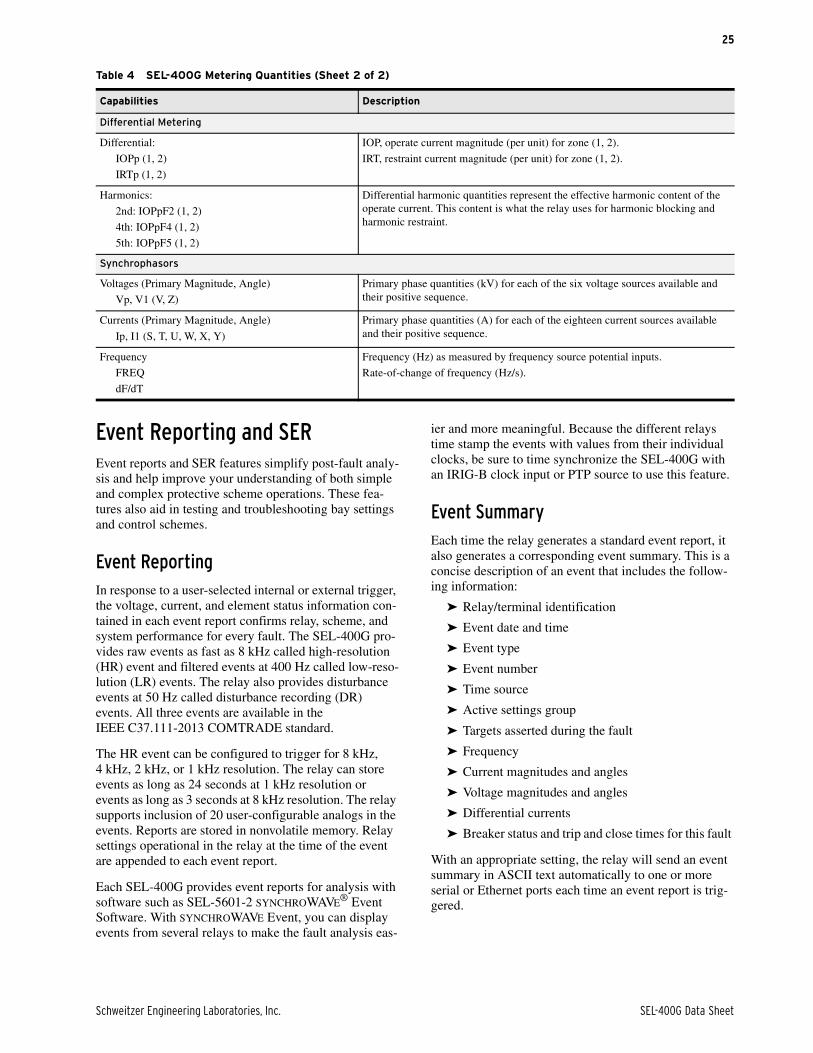
Schweitzer Engineering Laboratories, Inc. SEL-400G Data Sheet
25
Event Reporting and SEREvent reports and SER features simplify post-fault analy-sis and help improve your understanding of both simple and complex protective scheme operations. These fea-tures also aid in testing and troubleshooting bay settings and control schemes.
Event Reporting In response to a user-selected internal or external trigger, the voltage, current, and element status information con-tained in each event report confirms relay, scheme, and system performance for every fault. The SEL-400G pro-vides raw events as fast as 8 kHz called high-resolution (HR) event and filtered events at 400 Hz called low-reso-lution (LR) events. The relay also provides disturbance events at 50 Hz called disturbance recording (DR) events. All three events are available in the IEEE C37.111-2013 COMTRADE standard.
The HR event can be configured to trigger for 8 kHz, 4 kHz, 2 kHz, or 1 kHz resolution. The relay can store events as long as 24 seconds at 1 kHz resolution or events as long as 3 seconds at 8 kHz resolution. The relay supports inclusion of 20 user-configurable analogs in the events. Reports are stored in nonvolatile memory. Relay settings operational in the relay at the time of the event are appended to each event report.
Each SEL-400G provides event reports for analysis with software such as SEL-5601-2 SYNCHROWAVE® Event Software. With SYNCHROWAVE Event, you can display events from several relays to make the fault analysis eas-
ier and more meaningful. Because the different relays time stamp the events with values from their individual clocks, be sure to time synchronize the SEL-400G with an IRIG-B clock input or PTP source to use this feature.
Event Summary Each time the relay generates a standard event report, it also generates a corresponding event summary. This is a concise description of an event that includes the follow-ing information:
➤ Relay/terminal identification
➤ Event date and time
➤ Event type
➤ Event number
➤ Time source
➤ Active settings group
➤ Targets asserted during the fault
➤ Frequency
➤ Current magnitudes and angles
➤ Voltage magnitudes and angles
➤ Differential currents
➤ Breaker status and trip and close times for this fault
With an appropriate setting, the relay will send an event summary in ASCII text automatically to one or more serial or Ethernet ports each time an event report is trig-gered.
Differential Metering
Differential:
IOPp (1, 2)
IRTp (1, 2)
IOP, operate current magnitude (per unit) for zone (1, 2).
IRT, restraint current magnitude (per unit) for zone (1, 2).
Harmonics:
2nd: IOPpF2 (1, 2)
4th: IOPpF4 (1, 2)
5th: IOPpF5 (1, 2)
Differential harmonic quantities represent the effective harmonic content of the operate current. This content is what the relay uses for harmonic blocking and harmonic restraint.
Synchrophasors
Voltages (Primary Magnitude, Angle)
Vp, V1 (V, Z)
Primary phase quantities (kV) for each of the six voltage sources available and their positive sequence.
Currents (Primary Magnitude, Angle)
Ip, I1 (S, T, U, W, X, Y)
Primary phase quantities (A) for each of the eighteen current sources available and their positive sequence.
Frequency
FREQ
dF/dT
Frequency (Hz) as measured by frequency source potential inputs.
Rate-of-change of frequency (Hz/s).
Table 4 SEL-400G Metering Quantities (Sheet 2 of 2)
Capabilities Description

SEL-400G Data Sheet Schweitzer Engineering Laboratories, Inc.
26
SERUse this feature to gain a broad perspective of relay ele-ment operation. Items that trigger an SER entry are selectable and can include as many as 250 monitoring points such as input/output change-of-state, element pickup/dropout. The relay SER stores the latest 1000 events.
Load-Profile MonitoringThe SEL-400G provides analog signal profiling for as many as 20 analog quantities. Any analog quantity mea-sured or calculated by the SEL-400G can be selected for analog signal profiling. Signal sampling rates of 1, 5, 15, 30, and 60 minutes can be selected through settings. The analog signal profile report provides a comma-separated variable (CSV) list that can be loaded into any spread-sheet or database for analysis and graphical display.
SELOGIC enable/disable functions can start and stop sig-nal profiling based on Boolean or analog comparison conditions.
Substation Battery MonitoringThe SEL-400G measures and reports the substation bat-tery voltage. Programmable threshold comparators and associated logic provide alarm and control of batteries and charger. The relay also provides battery system ground detection.
The measured dc voltage is reported in the meter display via serial or Ethernet port communications, on the HMI, and in the event report. The event report data provide an oscillographic display of the battery voltage for monitor-ing substation battery voltage drop during trip, close, and other control operations.
Breaker Contact Wear MonitoringCircuit breakers experience mechanical and electrical wear every time they operate. Effective scheduling of breaker maintenance compares published manufacturer breaker wear data, interruption levels, and operation count with actual field data. The SEL-400G breaker monitoring function captures the total interrupted current and number of operations for as many as five three-pole breakers. Each time a monitored breaker trips, the relay integrates the interrupted current with previously stored current values. When the results exceed the threshold set with reference to the breaker wear curve, the relay can alarm via an output contact or the HMI.
The breaker wear monitor accumulates current by phase and so calculates wear for each pole separately. When first applying the relay, preload any previous estimated breaker wear. The incremental wear for the next interrup-tion, and all subsequent interruptions, adds to the pre-stored value for a total wear value. Reset the breaker monitor operation counters, cumulative interrupted cur-rents by pole, and percent wear by pole after breaker maintenance or installing a new breaker. The breaker wear monitor report lists all breakers, number of internal and external trips for each breaker, total accumulated rms current by phase, and the percent wear by pole.
SoftwareSEL Grid ConfiguratorSEL Grid Configurator combines an easy-to-use inter-face, powerful protection visualization, and comprehen-sive reporting to deliver a seamless and efficient configuration and commissioning experience. You want to be confident that your SEL-400G will perform as
expected, and SEL Grid Configurator is the key tool to help you verify that the relay configuration is exactly what you expect.
Protection Element ViewThe Protection Elements View in Grid Configurator pro-vides a single place to enable and configure settings for all protection functions.

Schweitzer Engineering Laboratories, Inc. SEL-400G Data Sheet
27
Protection VisualizationGrid Configurator enables graphical visualization of number of core protection functions of the SEL-400G. These visualization tools make your configuration pro-cess faster and give you confidence that the relay is con-figured just as you intend.
Device ReportingWhether during commissioning or normal operation, you need to quickly and accurately identify and download all relevant IED reports. The reporting view in Grid Config-urator enables you to view and download reports for one or many devices. Filter by date, report type, or device type and download reports to your computer.
Figure 33 Protection Element View
Figure 34 Protection Visualization View

SEL-400G Data Sheet Schweitzer Engineering Laboratories, Inc.
28
Architect IEC 61850 ConfiguratorDesign and configure the SEL-400G in IEC 61850 installations using Grid Configurator and Architect together. Architect provides a means to configure and document the IEC 61850 communications settings between SEL devices and devices from multiple manu-facturers.
SEL SYNCHROWAVE Event VisualizationUse SYNCHROWAVE Event to display and analyze distur-bance events. Records from multiple relays can be easily merged and time-aligned; allowing easy analysis of an event spanning one or more generating facilities.
TEAM Event CollectionUse ACSELERATOR TEAM® SEL-5045 Software for automatic event archiving and secure remote file retrieval. The same software can be used to archive
COMTRADE and SOE files from the SEL-400G and other relays in your generation facility.
Figure 35 View Reports
Figure 36 SYNCHROWAVE

Schweitzer Engineering Laboratories, Inc. SEL-400G Data Sheet
29
Diagrams and Dimensions
Figure 37 TEAM Works With Multiple Devices in a Variety of Configurations to Meet System Needs
Figure 38 SEL-400G Front-Panel Diagram
Modem ModemEthernet EthernetSerial Serial
SEL Relays SEL Relays
Other Vendor Relays
SEL Relays SEL Relays
SEL Relays
SEL Relays
SEL Relays SEL Relays
SEL-3620
SEL-3530
ACSELERATOR
Meter ReportsSEL-5630
ACSELERATOR®
Database
SUBSTATION
RESETTARGET
TRIP
ENABLED
ENTENTESCESC
SEL–400GPROTECTION AUTOMATION CONTROL
SCHWEITZERENGINEERINGLABORATORIES
PORT F
GENBKR TRIP
FIELD TRIP
PMVR TRIP
AUX TRIP
GEN ONLINE
46 CUR UNB
49 THERMAL
27/59 VOLT
60 LOP
87 GEN DIFF
87 GSU DIFF
REF
24 VOLTS/HZ
64 STA GND
64 FLD GND
40 LOF
32 REV PWR
81 O/U FREQ
78 OOS
SYS BACKUP
GENBKR FAIL

SEL-400G Data Sheet Schweitzer Engineering Laboratories, Inc.
30
Figure 39 SEL-400G Rear-Panel Diagram With Fixed Terminal Blocks
PORT 1
PORT 2
EIA-232
PORT 31
9
1
9
1
9
TIME IRIG–B
BAY 4BAY 3BAY 2BAY 1
01 02 03 04 05 06 07 08 09 10 11 12Y Y 31
GND
302928272625
IBWIAW ICW IAX IBX ICX
01 02 03 04 05 06 07 08 09 10 11 12Z Z
+Vdc 1
MONITOR
– /N+/H
POWER
–
484746454443424140393837363534333231302928272625242322212019181716151413121110090807060504030201 B
200
B
200
484746454443424140393837363534333231302928272625242322212019181716151413121110090807060504030201 C
300
C
300
484746454443424140393837363534333231302928272625242322212019181716151413121110090807060504030201 D
400
D
400
IAS IBS ICS IBTIAT ICT
OUT01 OUT02 OUT03 OUT04 OUT05 OUT06 OUT07 OUT08 OUT09 OUT10 OUT13 OUT14OUT11 OUT12 OUT15 IN01 IN02 IN03 IN04 IN05 IN06 IN07 IN08
OUT01 OUT02 OUT03 OUT04 OUT05 OUT06 OUT07 OUT08 OUT09 OUT10 OUT14 OUT15OUT11 OUT12 OUT13 IN01 IN02 IN03 IN04 IN05 IN06 IN07 IN08
OUT01 OUT02 OUT03 OUT04 OUT05 OUT06 OUT07 OUT08 OUT14 OUT15 IN01 IN02 IN03OUT09 OUT10 OUT11 OUT12 OUT13 IN04 IN05 IN06 IN07 IN08
LNK
ACT
LNK
ACT
LNK
ACT
LNK
PORT 5B PORT 5C ACTPORT 5D
100BASE-FX
PORT 5A
IAU IBU ICU VAV VBV VCV
13 14 15 16 17 18 19 20 21 22 23 24
VV1 VV2 VV3
196-1984.A
VCZVAZ
13 14 15 16 17 18 19 20 21 22 23 24
IAYIY1
IBYIY2
ICYIY3
VBZVZ2
196-1986.A

Schweitzer Engineering Laboratories, Inc. SEL-400G Data Sheet
31
Figure 40 SEL-400G Rear-Panel Diagram With Connectorized Terminal Blocks
Figure 2.5 I/O Interface Board INT2
Figure 2.6 I/O Interface Board INT4
Figure 2.7 I/O Interface Board INT7
PORT 1
PORT 2
EIA-232
PORT 31
9
1
9
1
9
TIME IRIG–B
BAY 4BAY 3BAY 2BAY 1
01 02 03 04 05 06 07 08 09 10 11 12Y Y 31
GND
302928272625
IAW IBW ICW IAX IBX ICX
01 02 03 04 05 06 07 08 09 10 11 12Z Z
+Vdc 1
MONITOR
– /N+/H
POWER
–
484746454443424140393837363534333231302928272625242322212019181716151413121110090807060504030201 B
200
B
200
484746454443424140393837363534333231302928272625242322212019181716151413121110090807060504030201 C
300
C
300
484746454443424140393837363534333231302928272625242322212019181716151413121110090807060504030201 D
400
D
400
IAS IBS ICS IAT IBT ICT
IN01 IN02 IN03 IN04 IN05 IN06 IN07 IN08 IN09 IN10 IN11 IN12 COM IN14 IN15 IN16 IN17 IN18 IN19 IN20 IN21 IN22 IN23 IN24 COMIN13OUT04OUT01 OUT02 OUT03 OUT05 OUT06 OUT07 OUT08
HS HSHS HS HS HSOUT01 OUT02 OUT03 OUT04 OUT05 OUT06 OUT07 OUT08 IN01 IN02 IN03 IN04 IN05 IN06 IN07 IN08 IN09 IN10 IN11 IN12 COM IN14 IN15 IN16 IN17 IN18 IN19 IN20 IN21 IN22 IN23 IN24 COMIN13
IN01 IN02 IN03 IN04 IN05 IN06 IN07 IN08 IN09 IN10 IN11 IN12 COM IN14 IN15 IN16 IN17 IN18 IN19 IN20 IN21 IN22 IN23 IN24 COMIN13OUT01 OUT02 OUT03 OUT04 OUT05 OUT06 OUT07 OUT08
LNK
ACT
LNK
ACT
LNK LNK
PORT 5A PORT 5B ACTPORT 5C ACT PORT 5D
10/100BASE-T / 100BASE-FX
IAU IBU ICU VAVVV1
VAVVV1
VBVVV2
VBVVV2
VCVVV3
VCVVV313 14 15 16 17 18
19 20
21 22
23 24 196-1983.A
IAYIY1
IBYIY2
ICYIY3 VAZ VAZ
VBZVZ2
VBZVZ2
VCZ VCZ13 14 15 16 17 18
19 20
21 22
23 24196-1985.A

SEL-400G Data Sheet Schweitzer Engineering Laboratories, Inc.
32
Figure 2.8 I/O Interface Board INT8
Figure 2.9 I/O Interface Board INTD
Figure 3 SEL-400G Dimensions for Rack- and Panel-Mount Models
LEGENDin
[mm] i9377a
*ADD 0.30 [7.6] FOR CONNECTORIZED RELAYS
RACK-MOUNT CHASSIS
TOP
*10.48[266.3]
1.12[28.4]
19.00[482.6]
13.97[354.8]
3.00[76.2]
11.00[279.4]
18.31[465.1]
FRONT
17.63[447.8]
13.85[351.8]
18.31[465.1]
3.00[76.2]
11.00[279.4]
Ø0.25 [6.4]
PANEL CUTOUT
19.80[502.9]
15.40[391.2] SIDEFRONT
TOP
*10.48[266.2]
1.12[28.6]
#10-32STUD
PANEL-MOUNT CHASSIS

Schweitzer Engineering Laboratories, Inc. SEL-400G Data Sheet
33
Specifications
ComplianceDesigned and manufactured under an ISO 9001 certified quality
management system
FCC Compliance StatementThis equipment has been tested and found to comply with the limits
for a Class A digital device, pursuant to part 15 of the FCC Rules. These limits are designed to provide reasonable protection against harmful interference when the equipment is operated in a commercial environment. This equipment generates, uses, and can radiate radio frequency energy and, if not installed and used in accordance with the instruction manual, may cause harmful interference in which case the user will be required to correct the interference at his own expense.
UL Listed to U.S. and Canadian safety standards (File E212775; NRGU, NRGU7)
CE Mark
GeneralAC Analog Inputs
Sampling Rate: 8 kHz
AC Current Inputs (Secondary Circuits)
Note: Current transformers are Measurement Category II.
Input Current
5 A Nominal: S, T, U, W, X, and Y terminals
1 A Nominal: S. T, U, W, X, and Y terminals
0.2 A/1 A/5 A Nominal: Y terminal only (REF)
Current Rating (With DC Offset at X/R = 10, 1.5 cycles)
5 A Nominal: 91.0 A
1 A Nominal: 18.2 A
0.2 A Nominal: 3.64 A
Continuous Thermal Rating
5 A Nominal: 15 A20 A (+55°C)
1 A Nominal: 3 A4 A (+55°C)
0.2 A Nominal: 0.6 A0.8 A (+55°C)
Saturation Current (Linear) Rating
5 A Nominal: 100 A
1 A Nominal: 20 A
0.2 A Nominal: 4 A
One-Second Thermal Rating
5 A Nominal: 500 A
1 A Nominal: 100 A
0.2 A Nominal: 20 A
One-Cycle Thermal Rating
5 A Nominal: 1250 A-peak
1 A Nominal: 250 A-peak
0.2 A Nominal: 50 A-peak
Burden Rating
5 A Nominal: 0.5 VA at 5 A
1 A Nominal: 0.1 VA at 1 A
0.2 A Nominal: 0.02 VA at 0.2 A
A/D Current Limit
Note: Signal clipping may occur beyond this limit.
5 A Nominal: 247.5 A
1 A Nominal: 49.5 A
0.2 A Nominal: 9.9 A
AC Voltage Inputs
Three-phase, four-wire (wye), and two PT delta and single-phase (only V terminal) connections are supported.
Rated Voltage Range: 55–250 VLN (V and Z terminals)
Operational Voltage Range: 0–300 VLN
Ten-Second Thermal Rating: 600 Vac
Burden: 0.1 VA @ 125 V
Frequency and Rotation
Rotation: ABCACB
Nominal Frequency Rating: 50 60
Frequency Tracking (Requires PTs):
Tracks between 5.0–120.0 HzBelow 5.0 Hz = 5.0 HzAbove 120.0 Hz = 120.0 Hz
Maximum Slew Rate: 30 Hz/s
Power Supply
24–48 Vdc
Rated Voltage: 24–48 Vdc
Operational Voltage Range: 18–60 Vdc
Vdc Input Ripple: 15% per IEC 60255-26:2013
Interruption: 20 ms at 24 Vdc, 100 ms at 48 Vdc per IEC 60255-26:2013
Burden: <40 W
48–125 Vdc or 110–120 Vac
Rated Voltage: 48–125 Vdc, 110–120 Vac
Operational Voltage Range: 38–140 Vdc85–140 Vac
Rated Frequency: 50/60 Hz
Operational Frequency Range: 30–120 Hz
Vdc Input Ripple: 15% per IEC 60255-26:2013
Interruption: 14 ms @ 48 Vdc, 160 ms @ 125 Vdc per IEC 60255-26:2013
Burden: <40 W, <90 VA
125–250 Vdc or 110–240 Vac
Rated Voltage: 125–250 Vdc, 110–240 Vac
Operational Voltage Range: 85–300 Vdc85–264 Vac
Rated Frequency: 50/60 Hz
Operational Frequency Range: 30–120 Hz
Vdc Input Ripple: 15% per IEC 60255-26:2013
Interruption: 46 ms @ 125 Vdc, 250 ms @ 250 Vdc per IEC 60255-26:2013
Burden: <40 W, <90 VA

SEL-400G Data Sheet Schweitzer Engineering Laboratories, Inc.
34
Control Outputs
Note: IEEE C37.90-2005 and IEC 60255-27:2013
Update Rate: 2.5 ms
Make (Short Duration Contact Current):
30 Adc1,000 operations at 250 Vdc2,000 operations at 125 Vdc
Limiting Making Capacity: 1000 W at 250 Vdc (L/R = 40 ms)
Mechanical Endurance: 10,000 operations
Standard
Rated Voltage: 24–250 Vdc110–240 Vrms
Operational Voltage Range: 0–300 Vdc0–264 Vrms
Operating Time: Pickup 6 ms (resistive load)Dropout 6 ms (resistive load)
Short-Time Thermal Withstand: 50 A for 1 s
Continuous Contact Current:
6 A at 70°C4 A at 85°C
Contact Protection: MOV protection across open contacts264 Vrms continuous voltage300 Vdc continuous voltage
Limiting Breaking Capacity/Electrical Endurance:
10,000 operations10 operations in 4 seconds, followed by
2 minutes idle
Hybrid (High-Current Interrupting)
Rated Voltage: 24–250 Vdc
Operational Voltage Range: 0–300 Vdc
Operating Time: Pickup 6 ms (resistive load)Dropout 6 ms (resistive load)
Short-Time Thermal Withstand: 50 Adc for 1 s
Continuous Contact Current:
6 Adc at 70°C4 Adc at 85°C
Contact Protection: MOV protection across open contacts300 Vdc continuous voltage
Limiting Breaking Capacity/Electrical Endurance:
10,000 operations4 operations in 1 second, followed by
2 minutes idle
Rated Voltage Resistive BreakInductive Break
L/R = 40 ms (DC)PF = 0.4 (AC)
24 Vdc 0.75 Adc 0.75 Adc
48 Vdc 0.63 Adc 0.63 Adc
125 Vdc 0.30 Adc 0.30 Adc
250 Vdc 0.20 Adc 0.20 Adc
110 Vrms 0.30 Arms 0.30 Arms
240 Vrms 0.20 Arms 0.20 Arms
Rated Voltage Resistive Break Inductive Break
24 Vdc 10 Adc 10 Adc (L/R = 40 ms)
48 Vdc 10 Adc 10 Adc (L/R = 40 ms)
125 Vdc 10 Adc 10 Adc (L/R = 40 ms)
250 Vdc 10 Adc 10 Adc (L/R = 20 ms)
Fast Hybrid (High-Speed High-Current Interrupting)
Rated Voltage: 24–250 Vdc
Operational Voltage Range: 0–300 Vdc
Operating Time: Pickup 0 µs (resistive load)Dropout 8 ms (resistive load)
Short-Time Thermal Withstand: 50 Adc for 1 s
Continuous Contact Current:
6 Adc at 70°C4 Adc at 85°C
Contact Protection: MOV protection across open contacts300 Vdc continuous voltage
Limiting Breaking Capacity/Electrical Endurance:
10,000 operations4 operations in 1 second, followed by
2 minutes idle
Note: Do not use hybrid control outputs to switch ac control signals. These outputs are polarity-dependent.
Control Inputs
Optoisolated (Use With AC or DC Signals)
INT2, INT7, and INT8 Interface Boards: 8 inputs with no shared terminals
INT4 and INTD Interface Boards:
6 inputs with no shared terminals18 inputs with shared terminals
(2 groups of 9 inputs with each group sharing one terminal)
Voltage Options: 24, 48, 110, 125, 220, 250 V
Current Drawn: <5 mA at nominal voltage<8 mA for 110 V option
DC Thresholds (Dropout Thresholds Indicate Level-Sensitive Option)
24 Vdc: Pickup 19.2–30.0 VdcDropout: <14.4 Vdc
48 Vdc: Pickup 38.4–60.0 Vdc;Dropout <28.8 Vdc
110 Vdc: Pickup 88.0–132.0 Vdc;Dropout <66.0 Vdc
125 Vdc: Pickup 105–150 Vdc;Dropout <75 Vdc
220 Vdc: Pickup 176–264 Vdc;Dropout <132 Vdc
250 Vdc: Pickup 200–300 Vdc;Dropout <150 Vdc
AC Thresholds (Ratings Met Only When Recommended Control Input Settings Are Used—see Table 2.1.)
24 Vac: Pickup 16.4–30.0 Vac rmsDropout: <10.1 Vac rms
48 Vac: Pickup 32.8–60.0 Vac rms;Dropout <20.3 Vac rms
110 Vac: Pickup 75.1–132.0 Vac rms;Dropout <46.6 Vac rms
125 Vac: Pickup 89.6–150.0 Vac rms;Dropout <53.0 Vac rms
220 Vac: Pickup 150.3–264 Vac rms;Dropout <93.2 Vac rms
250 Vac: Pickup 170.6–300 Vac rms;Dropout <106 Vac rms
Sampling Rate: 2 kHz
Rated Voltage Resistive Break Inductive Break
24 Vdc 10 Adc 10 Adc (L/R = 40 ms)
48 Vdc 10 Adc 10 Adc (L/R = 40 ms)
125 Vdc 10 Adc 10 Adc (L/R = 40 ms)
250 Vdc 10 Adc 10 Adc (L/R = 20 ms)
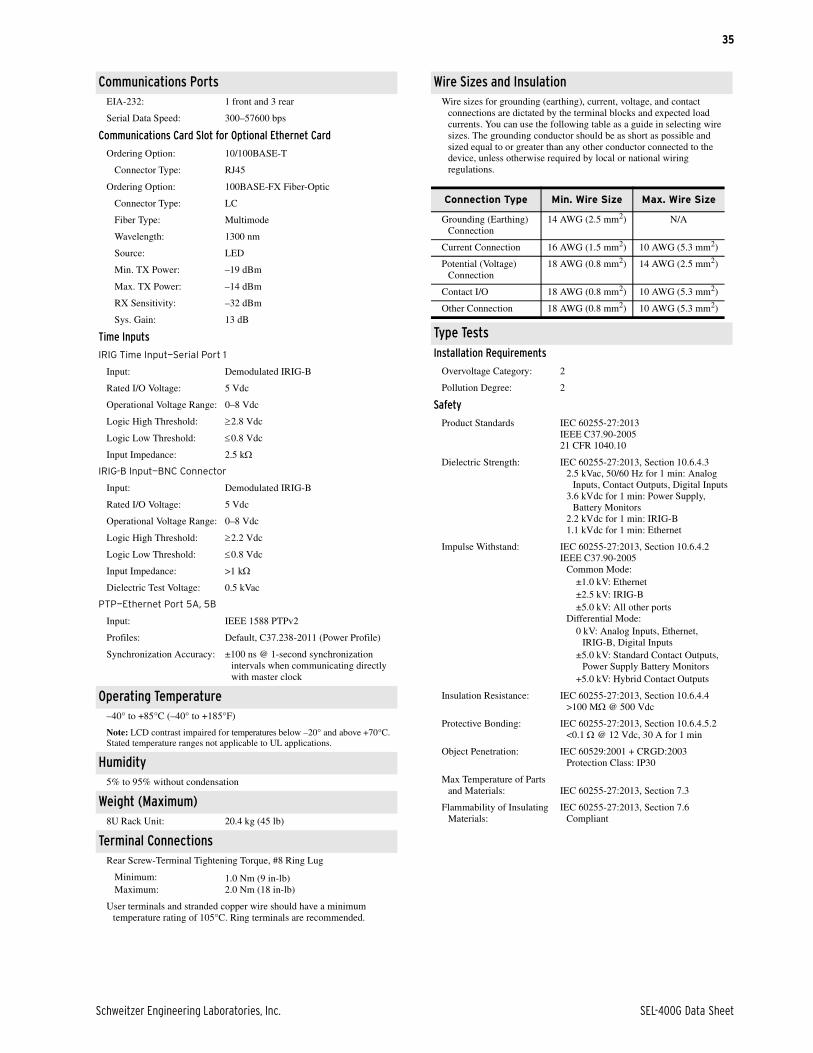
Schweitzer Engineering Laboratories, Inc. SEL-400G Data Sheet
35
Communications PortsEIA-232: 1 front and 3 rear
Serial Data Speed: 300–57600 bps
Communications Card Slot for Optional Ethernet Card
Ordering Option: 10/100BASE-T
Connector Type: RJ45
Ordering Option: 100BASE-FX Fiber-Optic
Connector Type: LC
Fiber Type: Multimode
Wavelength: 1300 nm
Source: LED
Min. TX Power: –19 dBm
Max. TX Power: –14 dBm
RX Sensitivity: –32 dBm
Sys. Gain: 13 dB
Time Inputs
IRIG Time Input—Serial Port 1
Input: Demodulated IRIG-B
Rated I/O Voltage: 5 Vdc
Operational Voltage Range: 0–8 Vdc
Logic High Threshold: 2.8 Vdc
Logic Low Threshold: 0.8 Vdc
Input Impedance: 2.5 k
IRIG-B Input—BNC Connector
Input: Demodulated IRIG-B
Rated I/O Voltage: 5 Vdc
Operational Voltage Range: 0–8 Vdc
Logic High Threshold: 2.2 Vdc
Logic Low Threshold: 0.8 Vdc
Input Impedance: >1 k
Dielectric Test Voltage: 0.5 kVac
PTP—Ethernet Port 5A, 5B
Input: IEEE 1588 PTPv2
Profiles: Default, C37.238-2011 (Power Profile)
Synchronization Accuracy: ±100 ns @ 1-second synchronization intervals when communicating directly with master clock
Operating Temperature–40° to +85°C (–40° to +185°F)
Note: LCD contrast impaired for temperatures below –20° and above +70°C.Stated temperature ranges not applicable to UL applications.
Humidity5% to 95% without condensation
Weight (Maximum)8U Rack Unit: 20.4 kg (45 lb)
Terminal ConnectionsRear Screw-Terminal Tightening Torque, #8 Ring Lug
Minimum:Maximum:
1.0 Nm (9 in-lb)2.0 Nm (18 in-lb)
User terminals and stranded copper wire should have a minimum temperature rating of 105°C. Ring terminals are recommended.
Wire Sizes and InsulationWire sizes for grounding (earthing), current, voltage, and contact
connections are dictated by the terminal blocks and expected load currents. You can use the following table as a guide in selecting wire sizes. The grounding conductor should be as short as possible and sized equal to or greater than any other conductor connected to the device, unless otherwise required by local or national wiring regulations.
Type TestsInstallation Requirements
Overvoltage Category: 2
Pollution Degree: 2
Safety
Product Standards IEC 60255-27:2013IEEE C37.90-200521 CFR 1040.10
Dielectric Strength: IEC 60255-27:2013, Section 10.6.4.32.5 kVac, 50/60 Hz for 1 min: Analog
Inputs, Contact Outputs, Digital Inputs3.6 kVdc for 1 min: Power Supply,
Battery Monitors2.2 kVdc for 1 min: IRIG-B1.1 kVdc for 1 min: Ethernet
Impulse Withstand: IEC 60255-27:2013, Section 10.6.4.2IEEE C37.90-2005
Common Mode:±1.0 kV: Ethernet±2.5 kV: IRIG-B±5.0 kV: All other ports
Differential Mode:0 kV: Analog Inputs, Ethernet,
IRIG-B, Digital Inputs±5.0 kV: Standard Contact Outputs,
Power Supply Battery Monitors+5.0 kV: Hybrid Contact Outputs
Insulation Resistance: IEC 60255-27:2013, Section 10.6.4.4>100 M @ 500 Vdc
Protective Bonding: IEC 60255-27:2013, Section 10.6.4.5.2<0.1 @ 12 Vdc, 30 A for 1 min
Object Penetration: IEC 60529:2001 + CRGD:2003Protection Class: IP30
Max Temperature of Parts and Materials: IEC 60255-27:2013, Section 7.3
Flammability of Insulating Materials:
IEC 60255-27:2013, Section 7.6Compliant
Connection Type Min. Wire Size Max. Wire Size
Grounding (Earthing) Connection
14 AWG (2.5 mm2) N/A
Current Connection 16 AWG (1.5 mm2) 10 AWG (5.3 mm2)
Potential (Voltage) Connection
18 AWG (0.8 mm2) 14 AWG (2.5 mm2)
Contact I/O 18 AWG (0.8 mm2) 10 AWG (5.3 mm2)
Other Connection 18 AWG (0.8 mm2) 10 AWG (5.3 mm2)

SEL-400G Data Sheet Schweitzer Engineering Laboratories, Inc.
36
Electromagnetic (EMC) Immunity
Product Standards: IEC 60255-26:2013IEC 60255-27:2013IEEE C37.90-2005
Surge Withstand Capability (SWC):
IEC 61000-4-18:2006 + A:2010IEEE C37.90.1-2012
Slow Damped Oscillatory, Common and Differential Mode:±1.0 kV±2.5 kV
Fast Transient, Common and Differential Mode:±4.0 kV
Electrostatic Discharge(ESD):
IEC 61000-4-2:2008IEEE C37.90.3-2001
Contact:±8 kV
Air Discharge:±15 kV
Radiated RF Immunity: IEEE C37.90.2-2004IEC 61000-4-3:2006 + A1:2007 +
A2:201020 V/m (>35 V/m, 80% AM, 1 kHz)
Sweep: 80 MHz to 1 GHz Spot: 80, 160, 450, 900 MHz
10 V/m (>15 V/m, 80% AM, 1 kHz)Sweep: 80 MHz to 1 GHz Sweep: 1.4 GHz to 2.7 GHz Spot: 80, 160, 380, 450, 900, 1850,
2150 MHz
Electrical Fast Transient Burst (EFTB):
IEC 61000-4-4:2012Zone A:
±2 kV: Communication ports±4 kV: All other ports
Surge Immunity: IEC 61000-4-5:2005Zone A:
±2 kVL-L±4 kVL-E±4 kV: Communication ports
Note: Cables connected to IRIG-B ports shall be less than 10 m in length for Zone A compliance.
Zone B:±2 kV: Communication ports
Conducted Immunity: IEC 61000-4-6:201320 V/m; (>35 V/m, 80% AM, 1 kHz)
Sweep: 150 kHz–80 MHzSpot: 27, 68 MHz
Power Frequency Immunity (DC Inputs):
IEC 61000-4-16:2015Zone A:
Differential: 150 VRMSCommon Mode: 300 VRMS
Power Frequency Magnetic Field:
IEC 61000-4-8:2009Level 5:
100 A/m; 60 Seconds; 50/60 Hz1000 A/m 1 to 3 Seconds; 50/60 Hz
Note: 50G1P 0.05 (ESS = N, 1, 2) 50G1P 0.1 (ESS = 3, 4)
Power Supply Immunity: IEC 61000-4-11:2004IEC 61000-4-17:1999/A1:2001/A2:2008IEC 61000-4-29:2000
AC Dips & InterruptionsRipple on DC Power InputDC Dips & InterruptionsGradual Shutdown/Startup (DC only)Discharge of CapacitorsSlow Ramp Down/UpReverse Polarity (DC only)
Damped Oscillatory Magnetic Field:
IEC 61000-4-10:2016Level 5:
100 A/m
EMC Compatibility
Product Standards: IEC 60255-26:2013
Emissions: IEC 60255-26:2013, Section 7.1Class A
47 CFR Part 15BClass A
Canada ICES-001 (A) / NMB-001 (A)
Environmental
Product Standards: IEC 60255-27:2013
Cold, Operational: IEC 60068-2-1:2007Test Ad: 16 hours at –40°C
Cold, Storage: IEC 60068-2-1:2007Test Ad: 16 hours at –40°C
Dry Heat, Operational: IEC 60068-2-2:2007Test Bd: 16 hours at +85°C
Dry Heat, Storage: IEC 60068-2-2:2007Test Bd: 16 hours at +85°C
Damp Heat, Cyclic: IEC 60068-2-30:2005Test Db: +25°C to +55°C, 6 cycles (12 +
12-hour cycle), 95% RH
Damp Heat, Steady State: IEC 60068-2-78:2013Severity: 93% RH, +40°C, 10 days
Cyclic Temperature: IEC 60068-2-14:2009Test Nb: –40°C to +80°C, 5 cycles
Vibration Resistance: IEC 60255-21-1:1988Class 2 Endurance, Class 2 Response
Shock Resistance: IEC 60255-21-2:1988Class 1 Shock Withstand, Class 1 Bump
Withstand, Class 2 Shock Response
Seismic: IEC 60255-21-3:1993Class 2 Quake Response
Reporting FunctionsHigh-Resolution Data
Rate: 8000 samples/second4000 samples/second2000 samples/second1000 samples/second
Output Format: Binary COMTRADE
Note: Per IEEE C37.111-2013, Common Format for Transient Data Exchange (COMTRADE) for Power Systems.
Event Reports
Length: 0.25–24 seconds (based on LER and SRATE settings)
Volatile Memory: 3 s of back-to-back event reports sampled at 8 kHz
Nonvolatile Memory: At least 4 event reports of a 3 s duration sampled at 8 kHz
Resolution: 2.5 ms
Disturbance Recorder
Length: 60–300 seconds(based on DRLER setting)
Volatile Memory: At least 1 DR event of 300 s duration sampled at 50 Hz
Nonvolatile Memory: At least 4 DR events of 300 s duration sampled at 50 Hz
Resolution: 20 ms for all elements
Event Summary
Storage: 100 summaries
Breaker History
Storage: 128 histories

Schweitzer Engineering Laboratories, Inc. SEL-400G Data Sheet
37
Sequential Events Recorder
Storage: 1000 entries
Trigger Elements: 250 relay elements
Resolution: 0.5 ms for contact inputs
Resolution: 2.5 ms for all elements
Processing SpecificationsAC Voltage and Current Inputs
8000 samples per second, 3 dB low-pass analog filter cut-off frequency at 3.1 kHz, ±5%
Digital filteringFull-cycle cosine after low-pass analog filtering
Analog Update Rate (Arate)
Protection and Control Processing
2.5 ms (minimum)
Control Points
64 remote bits64 local control bits32 latch bits in protection logic32 latch bits in automation logic
Relay Element Pickup Ranges and AccuraciesDifferential Elements (General)
Number of Zones: 2 (A, B, and C elements)
Number of Terminals: 6
TAP Pickup: (0.1–32.0) • INOM A secondary
TAP Range: TAPMAX/TAPMIN 35
Time-Delay Accuracy: ±0.1% plus ±2.5 ms
Differential Elements (Restraint)
Pickup Range: 0.1–4.0 per unit
Pickup Accuracy: 1 A nominal: ±5%5 A nominal: ±5% ±0.10 A
Pickup Time(If E87UNB = N):
1.25 cyc minimum1.25 cyc + 2.5 ms typical1.25 cyc + 5.0 ms max
Pickup Time(If E87UNB = Y):
0.5 cyc minimum0.5 cyc + 2.5 ms typical1.5 cyc max
Slope Setting Range: 5%–90%
Differential Elements (Unrestraint)
Pickup Range: (1.0–20.0) • TAP
Pickup Accuracy: ±5% of user setting, ±0.02 • INOM A
Pickup Time(Filtered Unrestraint):
0.7 cyc minimum0.85 cyc typical1.2 cyc maximum
Pickup Time(Raw Unrestraint):
0.25 cyc minimum0.5 cyc typical1.0 cyc maximum
Note: The raw unrestraint pickup is set to U87P • 2 • 2
Harmonic Elements (2nd, 4th, 5th)
Setting Range: OFF, 5–100% of fundamental
Pickup Accuracy: 1 A nominal ±5% ±0.02 A5 A nominal ±5% ±0.10 A
Time-Delay Accuracy: 0.1% + 1 processing interval
Frequency (Hz) Update Rate (ms)
20 < F 120 2.5
10 < F 20 5
5 < F 10 7.5
Negative-Sequence Differential Element
Pickup Range: 0.05–1 per unit
Slope Range: 5–100%
Pickup Accuracy: ±5% of user setting, ±0.02 • INOM A
Maximum Pickup/Dropout Time: 2 cycles
Winding Coverage: 2%
Incremental Restraint and Operating Threshold Current Supervision
Setting Range: 0.1–10.0 per unit
Accuracy: ±5% ±0.02 • INOM
Open-Phase Detection Logic
3 elements per terminal (S, T, U, Y)
Pickup Range
1 A Nominal: 0.04–1.00 A
5 A Nominal: 0.2–5.00 A
Maximum Pickup/Dropout Time: 1/2 cyc + 0.0025 ms
Restricted Earth Fault (REF)
Three Elements: 1 per IY1, IY2, IY3
Setting Range: 0.05–3 per unit
Pickup Accuracy
1 A Nominal: 0.01 A
5 A Nominal: 0.05 A
Maximum Pickup/Dropout Time: 1.25 cyc + Arate + 0.0025 s
Instantaneous/Definite-Time Overcurrent Elements (50)
Phase- and Negative-Sequence, Ground-Residual Elements
Setting Range
5 A Nominal: 0.25–100.00 A secondary, 0.01-A steps
1 A Nominal: 0.05–20.00 A secondary, 0.01-A steps
Accuracy (Steady State)
5 A Nominal: ±0.05 A plus ±3% of setting
1 A Nominal: ±0.01 A plus ±3% of setting
Transient Overreach (Phase and Ground Residual)
5 A Nominal: ±5% of setting, ±0.10 A
1 A Nominal: ±5% of setting, ±0.02 A
Transient Overreach (Negative Sequence)
5 A Nominal: ±6% of setting, ±0.10 A
1 A Nominal: ±6% of setting, ±0.02 A
Time-Delay Range: 0.00–400 s
Timer Accuracy: ±0.005 s plus ±0.1% of setting
Maximum Pickup/Dropout Time: 1.25 cyc + Arate + 0.005 s
Adaptive Time-Overcurrent Elements (51S and 51CV)
Setting Range (Adaptive Within the Range)
5 A Nominal: 0.25–16.00 A secondary, 0.01 A steps
1 A Nominal: 0.05–3.20 A secondary, 0.01 A steps
Accuracy (Steady State)
5 A Nominal: ±0.05 A plus ±3% of setting
1 A Nominal: ±0.01 A plus ±3% of setting
Transient Overreach
5 A Nominal: ±5% of setting, ±0.10 A
1 A Nominal: ±5% of setting, ±0.20 A

SEL-400G Data Sheet Schweitzer Engineering Laboratories, Inc.
38
Time Dial Range
U.S.: 0.50–15.00, 0.01 steps
IEC: 0.05–1.00, 0.01 steps
Timing Accuracy: ±1.25 cyc ± 5 ms ±4% of curve time (for current between 2 and 30 multiples of pickup)
Curves operate on definite time for current greater than 30 multiples of pickup.
Reset: 20 ms or electromechanical reset emulation time
Voltage-Controlled Overcurrent Element
Setting Range: 0.25–16.00 A, sec
Curve: U1–U5, C1–C5
Time Dial: 0.05–15.0
EM Reset: Y, N
Pickup Accuracy: ±1.25 cyc + Arate + 0.005s
Time-Delay Accuracy: ±0.1% of setting ±0.005 s
Voltage-Restrained Overcurrent Element
Setting Range: 2.00–16.00 A, sec
Curve: U1–U5, C1–C5
Time Dial: 0.50–15.00
EM Reset: Y, N
Pickup Accuracy: ±1.25 cyc + Arate + 0.005 s
Time-Delay Accuracy: ±0.1% of setting ±0.005 s
Phase Directional Elements (67)
Number: 4 (1 each for S, T, U, Y)
Outputs: Forward and reverse
Accuracy: ±0.05 secondary
Transient Overreach: +5% of set reach
Maximum Delay: 1.25 cycles + Arate + 5 ms
Ground Directional Elements
Number: 4 (1 each for S, T, U, Y)
Outputs: Forward and reverse
Polarization Quantity: Zero-sequence voltage
Operate Quantity: Zero-sequence current (3I0)(where 3I0 = IA + IB + IC)
Sensitivity: 0.05 • INOM A of secondary 3I0
Accuracy: ±0.05 secondary
Transient Overreach: +5% of set reach
Maximum Delay: 1.25 cycles + Arate + 5 ms
Negative-Sequence Directional Element
Number: 4 (1 each for S, T, U, Y)
Outputs: Forward and reverse
Polarization Quantity: Negative-sequence voltage
Operate Quantity: Negative-sequence current (3I2)
Sensitivity: 0.05 • INOM A of secondary 3I2
Accuracy: ±0.05 secondary
Transient Overreach: +5% of setting
Maximum Delay: 1.25 cycles + Arate + 5 ms
Undervoltage and Overvoltage Elements (27/59)
Setting Ranges
Phase Elements: 2–300 VLN in 0.01-V steps
Phase-to-Phase Elements: 4–520 VLL in 0.01-V steps
Sequence Elements: 2–300 VLN in 0.01-V steps
Pickup Accuracy (Steady State)
Phase Elements: ±3% of setting, ±0.5 V
Phase-to-Phase Elements Wye): ±3% of setting, ±0.5 V
Phase-to-Phase Elements (Delta): ±3% of setting, ±1 V
Sequence Elements: ±5% of setting, ±1 V
Pickup Accuracy (Transient Overreach)
Phase Elements: ±5%
Phase-to-Phase Elements Wye): ±5%
Phase-to-Phase Elements (Delta): ±5%
Sequence Elements: ±5%
Maximum Pickup/Dropout Time
Phase Elements: 1.25 cycles ± Arate + 5.0 ms
Phase-to-Phase Elements Wye): 1.25 cycles ± Arate + 5.0 ms
Sequence Elements: 1.25 cycles ± Arate + 5.0 ms
Time Delay Accuracy: ±0.1% of user setting ±5 ms
Inverse Time Delay Accuracy: ±1% of user setting ±5 ms
Underfrequency and Overfrequency Elements (81)
Setting Range: 5.01–119.99 Hz, 0.01-Hz steps
Accuracy, Steady State Plus Transient:
±0.005 Hz for frequencies between 40.00 and 70.00 Hz
Maximum Pickup/Dropout Time: 3.0 cycles
Setting Range, Undervoltage Blocking:
20.00–200.00 VLN (Wye) or VLL (Open-Delta)
Pickup Accuracy, Undervoltage Blocking: ±2% ±0.5 V
Time-Delay Range: 0.05–400.00 s, 0.01-s increment
Time-Delay Accuracy: ±0.1% of setting ±0.005 seconds
Accumulated Frequency Elements (81A)
Setting Range: 5.01–119.99 Hz, 0.01-Hz steps
Accuracy, Steady State Plus Transient:
±0.005 Hz for frequencies between 40.00 and 70.00 Hz
Maximum Pickup/Dropout Time:
0–400 s for 81ADand 0.5–6000 for band times
Time-Delay Range: 0.050–80.000 s, 0.005-s increment
Time-Delay Accuracy: ±0.1% of setting ±0.005 seconds
Rate-of-Change-of-Frequency Elements (81R)
Setting Range: –29.95 to 29.95 Hz/s, 0.05-Hz/s steps
Setting Range, Undervoltage Blocking:
20.00–200.00 VLN (wye) or VLL (open- delta)
Accuracy: ±0.005 Hz/s frequencies between 20.00 and 80.00 Hz
Pickup Accuracy, Undervoltage Blocking: ±2% ±0.5 V
Time-Delay Range: 0.050–80.000 s, 0.005 s increment
Time-Delay Accuracy: ±0.1% of setting ±5 ms seconds
Mho Phase Distance Elements
Number of Zones: 2
Pickup Range
5 A Nominal: OFF, 0.05 to 100 ohms, sec
1 A Nominal: OFF, 0.25 to 500 ohms, sec

Schweitzer Engineering Laboratories, Inc. SEL-400G Data Sheet
39
Offset Range
5 A Nominal: 0.00–10 ohms, sec
1 A Nominal: 0.00–50 ohms, sec
Pickup Accuracy: ±5% of user setting ±0.1 Inom
Maximum Operating Time: 1.00 cycle + Arate + 10 ms
Time Delay Accuracy: ±0.1% of user setting ± 5 ms
Breaker Inadvertent Energization Protection Logic
Setting Range, Overcurrent
5 A Nominal: 0.25–5.00 A secondary, 0.01 A steps
1 A Nominal: 0.05–1.00 A secondary, 0.01 A steps
Accuracy (Steady State)
5 A Nominal: ±0.05 A plus ±3% of setting
1 A Nominal: ±0.01 A plus ±3% of setting
Transient Overreach
5 A Nominal: ±5% of setting, ±0.10 A
1 A Nominal: ±5% of setting, ±0.20 A
Setting Range, Undervoltage: 1.00–300 V, sec in 0.01-V steps
Accuracy, Undervoltage: ±2% ±0.5 V
Time-Delay Range (Arm/Disarm): 0.0000–100 s
Time-Delay Range: 0.0000–10 s
Time-Delay Accuracy: ±0.1% of setting ±0.005 s
Volts/Hertz Elements (24)
Definite-Time Element
Setting Range: 100–200% steady state
Pickup Accuracy, Steady-State: ±1% of set point
Maximum Pickup/Dropout Time: 1.5 cycles + delay time setting
Time-Delay Range: 0.040–6000 s
Time-Delay Range, Reset: 0.040–6000 s
Time-Delay Accuracy: ±0.1% of setting ±5 ms
User-Definable Curve Element
Setting Range: 100–200%
Pickup Accuracy: ±1% of set point
Reset Time-Delay Range: 0.040–6000 s
Timing Accuracy: ±0.1% ±0.1% of curve time ±5 ms
Synchronism-Check Elements (25)
Slip Frequency PU Range: 0.005-0.500 Hz, 0.001 Hz steps
Slip Frequency PU Accuracy: ±0.0025 Hz plus ±2% of setting
Close Angle Range: 3.0-80 degrees, 0.1-degree steps
Close Angle Accuracy: ±3 degrees
Autosynchronism Elements (25A)
Frequency Matching
Raise/Lower: Digital Output
Setting Range, Control Pulse Mode:
OFF, Proportional Width, Fixed Duration, Proportional Frequency
Setting Range, Control Slope: 0.01–100 Hz/s
Setting Range, Control Pulse Period: 0.000–60 s
Setting Range, Control Pulse Duration: 0.000–60 s
Timing Accuracy: ±1% ±5.0 ms
Voltage Matching
Raise/Lower: Digital Output
Setting Range, Control Pulse Mode:
OFF, Proportional Width, Fixed Duration, Proportional Frequency
Setting Range, Control Slope: 0.01–100 V/s
Setting Range, Control Pulse Period: 0.000–60 s
Setting Range, Control Pulse Duration: 0.000–60 s
Timing Accuracy: ±0.1% ±5.0 ms
Time-Delay Range, Control Expiration: 0.000–400 s
Time-Delay Accuracy, Control Expiration: ±0.1% of setting ±5 ms
Breaker Failure Instantaneous Overcurrent
Setting Range
5 A Nominal: 0.50–50 A secondary, 0.01-A steps
1 A Nominal: 0.10–10.0 A, 0.01-A steps
Accuracy
5 A Nominal: ±0.05 A, ±3% of setting
1 A Nominal: ±0.01 A, ±3% of setting
Transient Overreach
5 A Nominal: ±5%, ±0.10 A
1 A Nominal: ±5%, ±0.02 A
Maximum Pickup Time: 1.25 cyc + Arate + 5 ms
Maximum Dropout Time: 1.25 cyc + Arate + 5 ms
Maximum Reset Time: 1.25 cyc + Arate + 5 ms
Time-Delay Range: 0.0000–20 s, 0.0025 s steps
Time-Delay Accuracy: ±0.1% of setting ±5 ms
Breaker Flashover Elements
Setting Range: 0.50–50 A secondary, 0.01 A steps
Accuracy, Steady State Plus Transient: ±5% of setting, ±0.10 A
Maximum Pickup/Dropout Time: 1.25 cyc + Arate + 2.5 ms
Time-Delay Range: 0.00–100.00 s, 0.01-s steps
Time-Delay Accuracy: ±0.1% of setting ±5 ms
Directional Overpower/Underpower Element (32)
Operating Quantities: OFF, 3PmF, 3QmF,3PqpF, 3QqpF(m = S, T, U, Y, Gqp = ST, TU, UW, WX)
Setting Range
5 A: –2000.00 to 2000.00 VA, 0.02 VA, sec steps
1 A: –400.00 to 400.00 VA, 0.02 VA, sec steps
Pickup Accuracy: ±3% of setting and ±5 VA, power factor >±0.5 at nominal frequency
Time-Delay Range: 0.000–400 s
Time-Delay Accuracy: ±0.1% of setting ±5 ms
Impedance-Based Loss of Field Element (40Z)
Zone 1
Setting Range, Mho Diameter
5 A Nominal: OFF, 0.1–100 ohms, sec
1 A Nominal: OFF, 0.5–500 ohms, sec

SEL-400G Data Sheet Schweitzer Engineering Laboratories, Inc.
40
Setting Range, Offset Reactance
5 A Nominal: –50.0 to 0 ohms, sec
1 A Nominal: –250.0 to 0 ohms, sec
Pickup Accuracy: ±3% at an impedance angle of –90 degrees
Zone 2
Setting Range, Mho Diameter
5 A Nominal: OFF, 0.1–100 ohms, sec
1 A Nominal: OFF, 0.5–500 ohms, sec
Setting Range, Offset Reactance
5 A Nominal: –50.0 to 50 ohms, sec
1 A Nominal: –250.0 to 250 ohms, sec
Setting Range, Supervision Angle: –20.0 to 0 deg in 0.1 deg steps
Pickup Accuracy: ±3% at an impedance angle of –90 degrees
Time-Delay Range: 0.000–400 s
Time-Delay Accuracy: ±0.1% of setting ±0.005 s
PQ-Based Loss of Field Element (40P)
Setting Range, Zones 1, 2, 4
5 A Nominal: –2000.00 to –1.00 VA sec, 0.01 VA sec step
1 A Nominal: –400.00 to –0.20 VA, sec, 0.01 VA sec step
Setting Range, Zones 2 and 4(Ranges Depend on GCC Point Specifying)
5 A Nominal: –2000.00 to 2000.00 VA sec, 0.01 VA sec steps
1 A Nominal: –400.00 to 400.00 VA sec, 0.01 VA sec steps
Pickup Accuracy: ±3% of setting and ±5 VA, power factor > ±0.5 at nominal frequency
Time-Delay Range: 0.000–400 s
Time-Delay Accuracy: ±0.1% of setting ±0.005 s
Current Unbalance Element (46)
Operate Quantity: I2GP, I2GPEQ
Setting Range %: OFF, 2–100
Level 1 Delay: 0.000–1000.000 s
Level 2 Time Dial: 1–100 s
Pickup Accuracy: Harmonic filtering is run every 5 s
Time-Delay Accuracy: ±0.1% of setting ±0.005 seconds
Harmonic Filtering Accuracy Range: 20–80 Hz of tracked frequency
Split-Phase Element (60P/N)
Setting Range
5 A Nominal: 0.1–100 A, sec, 0.01 A sec step
1 A Nominal: 0.02–20 A, sec, 0.01 A sec steps
0.2 A Nominal: 0.01–4 A, sec, 0.01 A sec steps
Time-Delay Range: 0.000–400 s
Time-Constant Range: 1–2400 s
Pickup Accuracy: ±1% of setting
Time-Delay Accuracy: ±0.1% of setting ±5.0 ms
100% Stator Ground Element (64G)
Setting Range, Voltage: 0.1-150.0 volts sec
Pickup Accuracy: ±3% of setting, ±0.1 V
Setting Range, Power Supervision
5 A Nominal: OFF, 1.00–2000 VA sec, 0.01 VA steps
1 A Nominal: OFF, 0.20–400 VA sec, 0.01 VA steps
Time-Delay Range: 0.000–400 s
Time-Delay Accuracy: ±0.1% of setting ±5.0 ms
Field Ground Element (64F)
Setting Range: OFF, 0.5–200 kilohms
Pickup Accuracy: Defined by the SEL-2664
Time-Delay Range: 0.000–400 seconds
Time-Delay Accuracy: ±0.1% of setting ±5.0 ms
Injection-Based Stator Ground Element (64S)
Setting Range: OFF, 0.1–10 kilohms
Pickup Accuracy: Defined by the SEL-2664S
Time-Delay Range: 0.000–400 seconds
Time-Delay Accuracy: ±0.1% of setting ±5.0 ms
Out-of-Step Element (78)
Setting Range, Mho and Blinder Reach
5 A Nominal: 0.05 to 100 ohms, sec
1 A Nominal: 0.25 to 500 ohms, sec
Setting Range, Current Supervision
5 A Nominal: 1.00–100 A, sec
1 A Nominal: 0.20–20 A, sec
Time-Delay Range, OOS: 0.000–1 s
Time-Delay Range, Trip: 0.000–1 s
Time-Delay Range, Trip Duration: 0.000–5 s
Setting Range, Generator Slip Counter: 1–5
Setting Range, System Slip Counter: OFF, 1–10
Setting Range, Total Slip Counter: OFF, 1–10
Time-Delay Range, Slip Counter Reset: 0.000–1 s
Accuracy (Steady State)
5 A Nominal: ±5% of setting plus ±0.01 A for SIR (source to line impedance ratio) < 30
±10% of setting plus ±0.01 A for 30 SIR 60
1 A Nominal: ±5% of setting plus ±0.05 A for SIR (source to line impedance ratio) < 30
±10% of setting plus ±0.05 A for 30 SIR 60
Transient Overreach: <5% of setting plus steady-state accuracy
Time-Delay Accuracy: ±0.1% of setting ±5.0 ms
Load Encroachment Element
Setting Range, Impedance Reach
5 A Nominal: 0.05 to 64 ohms, sec
1 A Nominal: 0.25 to 320 ohms, sec
Setting Range, Forward Load Angle: –90.0 to 90 deg
Setting Range, Reverse Load Angle: 90.0 to 270 deg
Impedance Accuracy: ±3%
Time-Delay Accuracy: ±0.1% of setting ±5.0 ms
Bay Control
Breakers: 4 maximum
Disconnects (Isolators): 10 maximum
Time-Delay Range: 0.020–2000 s, 5 ms step
Time-Delay Accuracy: ±0.1% of setting ±5.0 ms

Schweitzer Engineering Laboratories, Inc. SEL-400G Data Sheet
41
Station DC Battery System Monitor Rated Voltage: 15–300 Vdc
Operational Voltage Range: 0–350 Vdc
Input Sampling Rate: 2 kHz
Processing Rate: 5 ms
Operating Time: 1.5 seconds (element dc ripple)30 ms(all elements but dc ripple)
Setting Range
DC Settings: 1 Vdc Steps (OFF, 15–300 Vdc)
AC Ripple Setting: 1 Vac Steps (1–300 Vac)
Pickup Accuracy: ±10% ±2 Vdc (dc ripple)±3% ±2 Vdc (all elements but dc ripple)
Metering AccuracyAll metering accuracies are based on an ambient temperature of 20°C
and nominal frequency.
Absolute Phase-Angle Accuracy
IA, IB, and IC per Terminal: 0.2 A, 1 A, and 5 A
VA, VB, and VC Per Terminal: ±0.125°
Currents
Phase Current Magnitude
5 A Model: ±0.2% plus ±4 mA (0.05–3.0) • INOM
1 A Model: ±0.2% plus ±0.8 mA (0.05–3.0) • INOM
0.2 A Model: ±0.2% plus ±0.8 mA (0.05–0.5) • INOM±0.2% plus ±0.4 mA (0.5–3.0) • INOM
Phase Current Angle
5 A Model: ±0.6°in the current range (0.05–0.5) • INOM
±0.2°in the current range (0.5–3.0) • INOM
1 A Model: ±0.6°in the current range (0.05–0.5) • INOM
±0.2°in the current range (0.5–3.0) • INOM
0.2 A Model: ±1.5°in the current range (0.05–0.5) • INOM
±0.3°in the current range (0.5–3.0) • INOM
Sequence Current Magnitude
5 A Model: ±0.3% plus ±4 mA (0.5–100 A s)
1 A Model: ±0.3% plus ±0.8 mA (0.1–20 A s)
Sequence Current Angle
All Models: ±0.3°
Voltages
300 V Maximum Inputs
Phase and Phase-to-Phase Voltage Magnitude:
±2.5% ±1 V (5–33.5 V)±0.1% (33.5–300 V)
Phase and Phase-to-Phase Angle:
±1.0° (5–33.5 V)±0.5° (33.5–300 V)
Sequence Voltage Magnitude(V1, V2, 3V0):
±2.5%, ±1 V (5–33.5 V)±0.1% (33.5–300 V)
Sequence Voltage Angle (V1, V2, 3V0):
±1.0° (5–33.5 V)±0.5° (33.5–300 V)
Power
MW (P), Per Phase (Wye), 3 (Wye or Delta) Per Terminal
±1% (0.1–1.2) • INOM, 33.5–300 Vac, PF = 1, 0.5 lead, lag (1)±0.7% (0.1–1.2) • INOM, 33.5–300 Vac, PF = 1, 0.5 lead, lag (3)
MVAr (Q), Per Phase (Wye), 3 (Wye or Delta) Per Terminal
±1% (0.1–1.2) • INOM, 33.5–300 Vac, PF = 0, 0.5 lead, lag (1)±0.7% (0.1–1.2) • INOM, 33.5–300 Vac, PF = 0, 0.5 lead, lag (3)
MVA (S), Per Phase (Wye), 3 (Wye or Delta) Per Terminal
±1% (0.1–1.2) • INOM, 33.5–300 Vac, PF = 1, 0.5 lead, lag (1)±0.7% (0.1–1.2) • INOM, 33.5–300 Vac, PF = 1, 0.5 lead, lag (3)
PF, Per Phase (Wye), 3 (Wye or Delta) Per Terminal
±1% (0.1–1.2) • INOM, 33.5–300 Vac, PF = 1, 0.5 lead, lag (1)±0.7% (0.1–1.2) • INOM, 33.5–300 Vac, PF = 1, 0.5 lead, lag (3)
Energy
MWh (P), Per Phase (Wye), 3 (Wye or Delta)
±1% (0.1–1.2) • INOM, 33.5–300 Vac, PF = 1, 0.5 lead, lag (1)±0.7% (0.1–1.2) • INOM, 33.5–300 Vac, PF = 1, 0.5 lead, lag (3)
MVARh (Q), Per Phase (Wye), 3 (Wye or Delta)
±1% (0.1–1.2) • INOM, 33.5–300 Vac, PF = 0, 0.5 lead, lag (1)±0.7% (0.1–1.2) • INOM, 33.5–300 Vac, PF = 0, 0.5 lead, lag (3)
Demand/Peak Demand Metering
Time Constants: 5, 10, 15, ..., 250, 255, 300 minutes
IA, IB, and IC per Terminal: ±0.2% ±0.0008 • INOM, (0.1–1.2) • INOM
3I2 per Terminal 3I0 (IG) per Terminal (Wye-
Connected Only):±0.3% ±0.0008 • INOM,
(0.1–20) • INOM
Optional RTD Elements(Models Compatible With SEL-2600 Series RTD Module)
24 RTD inputs via SEL-2600 Series RTD Module and SEL-2800 Fiber-Optic Transceiver
Monitor Ambient or Other Temperatures
PT 100, NI 100, NI 120, and CU 10 RTD-Types Supported, Field Selectable
As long as 500 m Fiber-Optic Cable to SEL-2600 Series RTD Module
Synchrophasor
Number of Synchrophasor Data Streams: 5
Number of Synchrophasors for Each Stream:24 Phase Synchrophasors (6 Voltage and 18 Currents)8 Positive-Sequence Synchrophasors (2 Voltage and 6 currents)
Number of User Analogs for Each Stream: 16
Number of User Digitals for Each Stream: 64
Synchrophasor Protocol: IEEE C37.118-2011, 2014a
Synchrophasor Data Rate: As many as 60 messages per second
Synchrophasor Accuracy
Voltage Accuracy: ±1% Total Vector Error (TVE)Range 30–150 V, fNOM ±5 Hz
Current Accuracy: ±1% Total Vector Error (TVE)Range (0.1–2.0) • INOM A, fNOM ±5 Hz
Synchrophasor Data Recording:
Records as much as 120 sIEEE C37.232-2011, File Naming
Convention
Breaker Monitoring
Running Total of Interrupted Current (kA) per Pole: ±5% ±0.02 • INOM
Percent kA Interrupted for Trip Operations: ±5%
Percent Breaker Wear per Pole: ±5%
Compressor/Motor Start and Run Time: ±1 s
Time Since Last Operation: ±1 day

SEL-400G Data Sheet Schweitzer Engineering Laboratories, Inc.
42
Technical SupportWe appreciate your interest in SEL products and services. If you have questions or comments, please contact us at:
Schweitzer Engineering Laboratories, Inc.2350 NE Hopkins CourtPullman, WA 99163-5603 U.S.A.Tel: +1.509.338.3838Fax: +1.509.332.7990Internet: selinc.com/supportEmail: [email protected]

Schweitzer Engineering Laboratories, Inc. SEL-400G Data Sheet
43
Notes

44
© 2020-2021 by Schweitzer Engineering Laboratories, Inc. All rights reserved.
All brand or product names appearing in this document are the trademark or registered trademark of their respective holders. No SEL trademarks may be used without written permission. SEL products appearing in this document may be covered by U.S. and Foreign patents.
Schweitzer Engineering Laboratories, Inc. reserves all rights and benefits afforded under federal and international copyright and patent laws in its products, including without lim-itation software, firmware, and documentation.
The information in this document is provided for informational use only and is subject to change without notice. Schweitzer Engineering Laboratories, Inc. has approved only the English language document.
This product is covered by the standard SEL 10-year warranty. For warranty details, visit selinc.com or contact your customer service representative.
*PDS400G-01*
2350 NE Hopkins Court • Pullman, WA 99163-5603 U.S.A.Tel: +1.509.332.1890 • Fax: +1.509.332.7990selinc.com • [email protected]
SEL-400G Data Sheet Date Code 20210708


![400G+5G - img3.gelonghui.com · [Table_MainInfo][Table_Title] / 400G+5G [Table_Summary] 1 2 BAT 17% 40% ICP 3 400G 2019 2020 4 100G 400G (( ) 5G 1 4G 5G 6G/10G 25G 10G/100G 100G/200G/400G](https://static.fdocuments.us/doc/165x107/5e6c5d2df191f20be52e7612/400g5g-img3-tablemaininfotabletitle-400g5g-tablesummary-1-2-bat.jpg)