
SEISMIC QUALIFICATION OF STRUCTURES, SYSTEMS AND ...
94
GUIDE NO. AERB/NPP-PHWR/SG/D-23 GOVERNMENT OF INDIA SEISMIC QUALIFICATION OF STRUCTURES, SYSTEMS AND COMPONENTS OF PRESSURISED HEAVY WATER REACTORS AERB SAFETY GUIDE GUIDE NO. AERB/NPP-PHWR/SG/D-23 ATOMIC ENERGY REGULATORY BOARD
Transcript of SEISMIC QUALIFICATION OF STRUCTURES, SYSTEMS AND ...
GUIDE NO. AERB/NPP-PHWR/SG/D-23
GOVERNMENT OF INDIA
SEISMIC QUALIFICATION OF STRUCTURES,SYSTEMS AND COMPONENTS OF
PRESSURISED HEAVY WATER REACTORS
AERB SAFETY GUIDE
GU
IDE
NO
. AE
RB
/NP
P-P
HW
R/S
G/D
-23
ATOMIC ENERGY REGULATORY BOARD
AERB SAFETY GUIDE NO. AERB/NPP-PHWR/SG/D-23
SEISMIC QUALIFICATION OF STRUCTURES,SYSTEMS AND COMPONENTS OF
PRESSURISED HEAVY WATER REACTORS
Atomic Energy Regulatory BoardMumbai-400 094
India
September 2009

Price
Order for this guide should be addressed to:
The Administrative OfficerAtomic Energy Regulatory Board
Niyamak Bhavan-A,Anushaktinagar,
Mumbai-400 094,India

FOREWORD
Activities concerning establishment and utilisation of nuclear facilities and use ofradioactive sources are to be carried out in India in accordance with the relevantprovisions of the Atomic Energy Act, 1962. In pursuance of the objective to ensuresafety of members of the public and occupational workers, as well as protection of theenvironment, the Atomic Energy Regulatory Board has been entrusted with theresponsibility of laying down safety standards and framing rules and regulations forsuch activities. The Board has, therefore, undertaken a programme of developing safetystandards, safety codes and related guides and manuals for the purpose. While some ofthe documents cover aspects such as siting, design, construction, operation, qualityassurance and decommissioning, other documents cover regulatory aspects of thesefacilities.
Safety codes and safety standards are formulated on the basis of nationally andinternationally accepted safety criteria for design, construction and operation of specificequipment, systems, structures and components of nuclear and radiation facilities. Safetycodes establish the safety objectives and set minimum requirements that shall be fulfilledto provide adequate assurance for safety. Safety guides elaborate various requirementsand furnish approaches for their implementation. Safety manuals deal with specifictopics and contain detailed scientific and technical information on the subject. Thesedocuments are prepared by experts in the relevant fields and are extensively reviewedby Advisory Committees of the Board before they are published. The documents arerevised when necessary, in the light of experience and feedback from users as well asnew developments in the field.
This safety guide provides methods for seismic qualification of structures, systems andcomponents (SSC) of Pressurised Heavy Water Reactors (PHWR) based nuclear powerplants to meet the requirement of assessment of SSC against earthquake loads specifiedin safety code AERB/SC/D, ‘Code of Practice on Design for Safety in PressurisedHeavy Water Based Nuclear Power Plants’. In drafting this guide, information containedin relevant documents published by the International Atomic Energy Agency (IAEA),American Society of Civil Engineers (ASCE), US Department of Energy (US DOE),The Institution of Electrical and Electronics Engineers (IEEE), Japan Electric Associationand other international publications have been extensively used. Though this guide isprepared for PHWR based nuclear power plants, it is generally applicable for othertypes of nuclear power plants also.
Consistent with the accepted practice, ‘shall’ and ‘should’ are used in the document todistinguish between a firm requirement and a desirable option, respectively. Appendicesare an integral part of the document, whereas annexures and references are included toprovide further information on the subject that might be helpful to the user. Approachesfor implementation different to those setout in the Guide may be acceptable, if theyprovide comparable assurance against undue risk to the health and safety of theoccupational workers and the general public and protection of the environment.
i

The guide applies only for facilities built after the issue of the document. However,during periodic safety review, a review for applicability of current guide for existingfacilities would be performed.
For aspects not covered in this guide, applicable national and international standards,codes and guides acceptable to AERB should be followed. Non-radiological aspectssuch as environmental protection and industrial safety are not explicitly considered.Industrial safety is to be ensured through compliance with the applicable provisions ofthe Factories Act, 1948 and the Atomic Energy (Factories) Rules, 1996 and theEnvironmental protection Act, 1984.
This guide has been prepared by specialists in the field drawn from the Atomic EnergyRegulatory Board, Bhabha Atomic Research Centre, Indira Gandhi Centre for AtomicResearch, Nuclear Power Corporation and other consultants. It has been reviewed bythe relevant AERB Advisory Committee on Codes and Guides and the AdvisoryCommittee on Nuclear Safety.
AERB wishes to thank all individuals and organisations who have prepared and reviewedthe draft and helped in its finalisation. The list of persons, who have participated in thistask, along with their affiliations, is included for information.
(S.K. Sharma) Chairman, AERB
ii
DEFINITIONS
Analysis
A process of mathematical or other logical reasoning or deduction that leads from statedpremises to the conclusion/response/outcome/adequacy of a system or any other itemof interest.
Anchor
A structural member embedded in the concrete or attachment to other structures towhich a liner, embedment, or surface mounted item is attached.
Component
The smallest part of a system necessary and sufficient to consider for system analysis.
Earthquake
Vibration of earth caused by the passage of seismic waves radiating from the source ofelastic energy.
Inspection
Quality control actions, which by means of examination, observation or measurement,determine the conformance of materials, parts, components, systems, structures as wellas processes and procedures with predetermined quality requirements.
Model
An analytical representation or quantification of a real system and the ways in whichphenomena occur within that system, used to predict or assess the behaviour of the realsystem under specified (often hypothetical) conditions.
Monitoring
The continuous or periodic measurement of parameters for reasons related to thedetermination, assessment in respect of structure, system or component in a facility orcontrol of radiation.
Normal Operation
Operation of a plant or equipment within specified operational limits and conditions. Incase of a nuclear power plant, this includes, start-up, power operation, shutting down,shutdown state, maintenance, testing and refuelling.
Nuclear Power Plant (NPP)
A nuclear reactor or a group of reactors together with all the associated structures,systems, equipment and components necessary for safe generation of electricity.
Operating Basis Earthquake (OBE)
An earthquake which, considering the regional and local geology and seismology and
iii

specific characteristics of local sub-surface material, could reasonably be expected toaffect the plant site during the operating life of the plant. The features of a nuclearpower plant necessary for continued safe operation are designed to remain functional,during and after the vibratory ground motion caused by the earthquake.
Operation
All activities following and prior to commissioning performed to achieve, in a safemanner, the purpose for which a nuclear/radiation facility is constructed, includingmaintenance.
Review
Documented, comprehensive and systematic evaluation of the fulfillment ofrequirements, identification of issues, if any.
Safe Shutdown Earthquake (SSE)
The earthquake which is based upon an evaluation of the maximum earthquake potentialconsidering the regional and local geology, seismology and specific characteristics ofthe local sub-surface material. It is that earthquake which produces the maximumvibratory ground motion for which certain structures, systems and components aredesigned to remain functional. These structures, systems, and components are thosewhich are necessary to assure
••••• the integrity of the reactor coolant pressure boundary; or
••••• the capability to shutdown the reactor and maintain it in a safe shutdowncondition; or
••••• the capability to prevent the accident or to mitigate the consequences ofaccidents which could result in potential off-site exposures higher than thelimits specified by the regulatory body; or
••••• the capacity to remove residual heat.
Safety Function
A specific purpose that must be accomplished for safety.
Specification
A written statement of requirements to be satisfied by a product, a service, a material orprocess, indicating the procedure by means of which it may be determined whether thespecified requirements are satisfied.
Structure
The assembly of elements which supports/houses the plants, equipment and systems.
Structural integrity
The ability of a structure to withstand prescribed loads.
iv
CONTENTS
FOREWORD ...................................................................................... i
DEFINITIONS ...................................................................................... iii
1. INTRODUCTION ..................................................................... 11.1 General ......................................................................... 11.2 Objective ...................................................................... 11.3 Scope ............................................................................ 11.4 Structure of the Document in Relation to
Earthquake Scenario ..................................................... 1
2. SEISMIC QUALIFICATION OF CIVIL STRUCTURES ....... 82.1 Seismic Categorisation ................................................. 82.2 Modelling of Structures ................................................ 82.3 Analysis of Structures ................................................... 142.4. Soil-structure Interaction - Modelling and Analysis ..... 222.5 Generation of Input for Floor Mounted
Equipment (Subsystem) Analysis ................................. 282.6 Design of Buildings/Structures ..................................... 33
3. SEISMIC QUALIFICATION OF EQUIPMENT ...................... 343.1 General ......................................................................... 343.2 Classification ................................................................ 343.3 Structure Equipment Interaction ................................... 343.4 Equipment Stiffness and Mass Modelling .................... 353.5 Modelling of Damping ................................................. 363.6 Analysis Methods ......................................................... 36
4. SEISMIC QUALIFICATION OF PIPING ................................ 384.1 General ......................................................................... 384.2 Classification ................................................................ 384.3 Structure-Equipment-Piping Interaction ....................... 384.4 Mathematical Idealisation of Piping System ................ 384.5 Dynamic Analysis Methods .......................................... 414.6 Codal Qualification ...................................................... 44
5. SEISMIC QUALIFICATION BY TESTING ............................ 455.1 General ......................................................................... 455.2 Equipment Seismic Test Qualification Specification ... 465.3 Seismic Qualification Test Plan .................................... 46

6. MINIMUM CONTENTS OF SEISMIC QUALIFICATIONREPORT .................................................................................... 566.1 General ......................................................................... 566.2 Safety Classification and Seismic Categorization ........ 566.3 Design Specification..................................................... 566.4 Seismic Input ................................................................ 566.5 Seismic Analysis ........................................................... 576.6 Acceptance Criteria ...................................................... 596.7 Compliance to Quality Assurance Plan ........................ 60
APPENDIX 1: GUIDELINES FOR CALCULATING SPRINGCONSTANTS, MASSES AND LOCATIONSOF MASSES FOR RECTANGULAR BASINS .......... 61
APPENDIX 2: SOIL SPRING AND DASHPOT CONSTANTS ......... 63
ANNEXURE 1: SPECIAL STRUCTURES ........................................... 65
ANNEXURE 2: GENERAL DESIGN GUIDELINES FORSTRUCTURES, EQUIPMENT AND PIPING ............ 68
REFERENCES ......................................................................................... 79
LIST OF PARTICIPANTS ....................................................................... 80
WORKING GROUP ................................................................................ 80
ADVISORY COMMITTEE ON CODES, GUIDES ANDASSOCIATED MANUALS FOR SAFETY IN DESIGN OFNUCLEAR POWER PLANTS (ACCGD) ............................................... 81
ADVISORY COMMITTEE ON NUCLEAR SAFETY (ACNS) ............ 82
PROVISIONAL LIST OF SAFETY CODES, GUIDES ANDMANUALS ON DESIGN OF PRESSURISED HEAVY WATERREACTOR................................................................................................ 83
1
1. INTRODUCTION
1.1 General
This Safety Guide has been prepared as a part of AERB's programme forestablishing Design Safety Guides relating to Nuclear Power Plants (NPPs).It supplements the other related Safety Guides and suggests methods fordesigning structures, systems and components (SSCs) against earthquakesloading.
The steps involved in the design of SSCs of NPP to resist seismic loading are:
(a) Generating design ground motion;
(b) Performing analysis to generate response of the SSCs; and
(c) Verification of design of SSCs for the response generated in step (b).
The first step of generating design ground motion is covered in AERB SafetyGuide AERB/SG/S-11. The purpose of the present Safety Guide is to giveguidelines for the above steps (b) and (c) for the seismic qualification of SSCsof an NPP.
1.2 Objective
AERB Safety Code AERB/SC/D “Code of Practice on Design for Safety inPressurised Heavy Water Based Nuclear Power Plants” outlines therequirement of protection against natural phenomena as follows : Structures,systems and components necessary to assure the capability for shutdown,residual heat removal and confinement of radioactive material shall be designedto remain functional throughout the plant life in the event of natural phenomenasuch as earthquakes, cyclones and floods. This guide provides the guidelinesfor implementation of the same with respect to earthquake loads.
1.3 Scope
The main emphasis in the Safety Guide is to provide guidelines for seismicqualification of SSCs of Pressurised Heavy Water Reactors (PHWRs) byanalysis and testing. Though this guide is prepared for PHWR based nuclearpower plants, it is generally applicable for other types of nuclear power plantsalso.
1.4 Structure of the Document in Relation to Earthquake Scenario
Although earthquakes can cause many types of damage, major effects expectedat site are related to the vibrations induced in the structures, systems andcomponents. Earthquakes produce random ground motions, which arecharacterised by simultaneous but statistically independent horizontal and
vertical components. The designer is primarily interested in the effects ofearthquake ground motion on the SSCs; viz. stresses and deformations. Thedamage potential of an earthquake (due to excessive stresses and deformations)depends on the magnitude (Richter scale) and the shortest distance of a faultline from the nuclear power plant.
A larger magnitude earthquake may cause higher stresses and largerdeformations. On the other hand, probability of such an earthquake event tooccur during the life of the NPP is very low. This extreme loading with lowprobability has led to the seismic design of an NPP for two levels of earthquake.(see sec. 2.1)
An earthquake which is reasonably expected to occur during the life of astructure, is termed as Operating Basis Earthquake (OBE) or S1. The SSCsare expected to resist this level of earthquake within their elastic limits andmaintain functionality during and after the earthquake to enable subsequentoperation. Seismic Category 1 and 2 SSCs are designed for this level ofearthquake (see AERB/NPP-PHWR/SG/D-1 [1] for seismic categorisation).
The most severe earthquake, which could occur with a very low probability,within the life of an NPP, is termed as Safe Shutdown Earthquake (SSE) orS2. Earthquakes beyond S1 limit may result in some damage and deformationbeyond elastic limit and subsequent operation may not be possible withoutrepair/replacement of some SSCs. Beyond S1 limit and upto S2 limit the reactorshould be capable of being shutdown and maintained in a shutdown state witha coolable geometry. Seismic Category 1 SSCs are designed for this level ofearthquake.
Seismic Category 3 structures and components are designed as per the nationalpractice e.g. civil structures of Seismic Category 3 are designed as per theground motion and the methodology given in IS 1893 [13].
In order to specify the ground motion corresponding to these two differentlevels of earthquakes; one has to use seismological data, such as magnitudeand frequency of occurrence for a specific site supplemented by geologicaldata (e.g., active faults, depth of focus, soil condition, attenuation law etc.)
Peak ground acceleration of the S1 and S2 earthquakes is one possible indicatorof the severity of the earthquake, but that alone does not give designer enoughinformation because the frequency content is also important. The form of theseismic motion used for seismic analysis can be described by time history(accelerogram) or response spectrum. Each point on the response spectrumindicates the maximum acceleration (in case of acceleration response spectrum)of a single degree of freedom oscillator with certain frequency and damping.
One way to specify the expected ground motion is to use an accelerogram orresponse spectrum of a past earthquake with a proper magnitude, which was
2

recorded at an appropriate distance. However, no two earthquakes are everalike, and there is a big difference between the records of earthquakes withsimilar magnitude and distance from the source. The scatter among thecorresponding structural responses is even greater. This makes the usefulnessof this approach, i.e. a single record defining a design earthquake, highlyquestionable.
To overcome this problem, standard response spectra have been generated byusing acceleration records of many past earthquakes and normalising, averagingand smoothing the resultant curves. One such standard response spectrum isthe one given in AERB Safety Guide AERB/SG/S-11 [3]. The spectrum isnormalised for a Peak Ground Acceleration (PGA) of 1g and it should bescaled in proportion to the PGA of the design earthquake.
By being selective in the usage of past earthquake records in terms ofmagnitude, distance from epicenter and soil conditions, it is possible to producesite dependent response spectrum. Such site dependent spectra have beengenerated for a few potential sites in India and the envelope of these may beused.
The ground motion prescribed for a particular site is the ground motion thatwould occur on the surface of the ground, if the structures were not present,called as control motion or free-field motion. However, the ground motionactually introduced at the base of a structure may be influenced by the motionof the structure itself such that it differs considerably from the free-field motion.
In case of a flexible structure, located on firm ground (rock), the structure cantransmit little energy back into the soil and the free-field motion is an adequatemeasure of the foundation motion (see sec.2.4.1). In case of a stiff structure,located on soft soil, there is considerable exchange of energy between thestructure and the soil and base motion may differ drastically from the free-field motion.
It is possible to compute the motion at some depth in the soil profile, such assoil-rock interface. Soil properties required for soil-structure interactionanalysis are derived from tests on soil (see sec. 2.4.2). This process oftransferring the motion from the surface to the soil-rock interface is called de-convolution. This de-convolved motion may then be used as input to a threedimensional mathematical model of the soil and structure (see sec. 2.4.3).Neglecting this effect of soil-structure interaction will be conservative in mostcases, as the actual motion at the base of the structure in presence of soil-structure interaction is less than the free field motion.
The soil-structure interaction introduces one vertical and two orthogonalhorizontal translation motions, two orthogonal rocking motions and a torsionalmotion. These can be accounted for in the analyses by modeling the soil bythree translation, two rocking and one torsional springs (see sec. 2.4.4).
3
A nuclear power plant consists of many SSCs; and a single complete model ofthe entire plant would be too cumbersome. The mathematical solution ofsuch a single model may also become difficult. Thus the analyst should identifythe main systems and subsystems. Major structures, which are considered inconjunction with foundation media to form a soil-structure interaction model,constitute the main system. Other SSCs, attached to the main system, shouldconstitute the subsystems. Certain criteria should be used to decide if aparticular subsystem should be taken into account in the analysis of the mainsystem. Such decoupling criteria (see sec. 2.2.8) define some limits on therelative mass ratio between the subsystem and the supporting main system,with more severe limits, when there is a possibility of resonance between thesubsystem and the main system.
For design of structures and for ground-mounted equipment, the descriptionof the ground motion in terms of response spectrum is adequate. It is alsoadequate for large, massive equipment such as calandria and end-shieldassembly, which has significant interaction with the supporting structure andhas to be modeled along with the primary structure in a coupled analysis.However, for non-interacting or marginally interacting equipment mountedon floors, the ground motion may be filtered and amplified by the interveningstructure to produce a narrow band amplified motion. Just as ground responsespectra are used for design of structures or ground-supported equipment, floorresponse spectra are used for designing floor-mounted equipment (see sec.2.5). Although methods are available for conversion of ground response spectrato floor response spectra (so called spectra to spectra methods), the mostfrequently used method is the one in which the floor spectra are derived froma time history analysis of the primary structure.
For this purpose, the designer develops synthetic time histories made by thesummation of numerous Sine waves of different frequencies. The amplitudesand phase angles of these are adjusted until the response spectrum of thesynthetic time history matches the given ground response spectrum (see sec.2.3.2). This involves certain amount of trial and error; and several iterationsare required before a satisfactory synthetic time history can be obtained. Evenin this case, a certain amount of residual mismatch between the two spectra isunavoidable. In order to avoid the unconservatism resulting from this, it isnecessary to use multiple synthetic time-histories.
Once the input motion has been specified, the response of the structure isobtained by analysing a mathematical model of the structure. The mathematicalmodel consists of stiffness, mass and damping properties of the structure. Thestructures are often analysed in multiple steps (see sec. 2.2.2).
The first step may use a simplified stick model of the structure and calculateonly the response accelerations and displacements. These are used insubsequent detailed analysis of the complete structure. For the simplified
4

5
stick model, the stiffness properties of the structure are calculated by simpleformulas where applicable or from a static analysis of the structure (see sec.2.2.2). In a Finite Element Model, the stiffness formulation is built-in; needingonly the material properties, such as elastic and shear moduli, Poison's ratio(see sec. 2.2.4) and the geometric details.
Modeling of mass, although relatively straightforward in most cases, requiresspecial consideration for SSCs containing liquids (see sec. 2.2.6). When astructure containing liquid (e.g. spent fuel storage bay) is subjected to anearthquake excitation, a certain portion of the liquid acts as if it were a solidmass in contact with the walls. The force exerted by this mass is called theimpulsive force. The acceleration also induces oscillations of the liquid,contributing to additional dynamic pressure on the wall and the bottom. Thiscan be thought as a certain portion of the liquid responding as if it were a solidmass connected to the walls through flexible springs. The associated force iscalled the convective force. Fluids contained within a structure/equipmentshall be modeled to represent both impulsive and convective (sloshing) effects.
Damping, as a material property, depends on the stress levels. For S1earthquake, the stresses are within elastic limit and the damping values aregenerally lower than those for S2 earthquake, which is expected to result ininelastic deformation (see sec. 2.2.7).
The mathematical model of the structure can be analysed by either time-historymethod (see sec. 2.3.2) or response spectrum method (see sec. 2.3.3). Theresponse spectrum method calculates only the maximum response of thestructure in each mode. Since the maxima in different modes may occur atdifferent times, special techniques are required for combining the modalresponses (see sec. 2.3.5). Similar considerations apply to combination ofresponses from the two horizontal and one vertical component of earthquakemotion (see sec. 2.3.6 & 2.3.7).
Response of some components with simple geometry can be calculated byequivalent static method. This method approximates the component as a singledegree of freedom structure having frequency equal to the fundamentalfrequency and accounts for the neglected modes by using a factor of 1.5 onthe spectral acceleration (see sec. 2.3.4).
For SSCs, which are not specifically modeled in the dynamic model of theprimary structure (i.e. they are decoupled and analysed separately), inputmotion at their support location is required either in the form of a time historyor in the form of floor response spectrum. The floor response spectrum showspeaks at the natural frequencies of the primary structure. These naturalfrequencies could vary due to uncertainties in the material properties of soil,structure and approximations in modeling. To account for these effects, thefloor response spectrum peaks are broadened (see sec. 2.5.2). Equivalent
6
broadening is required in time history also (see sec. 2.5.3). However, thebroadening is not required, when equipment (which was coupled with theprimary structure) is analysed later using a detailed model (see sec. 2.5.4).
The calculated seismic forces and moments shall be combined with the forcesand moments due to other loadings in appropriate load combinations and theSSCs designed as per AERB standards on Civil Engineering Design (see sec.2.6), or ASME Code for mechanical equipment and piping.
The analytical procedures for evaluating the seismic response of equipment(see section 3) and piping (see section 4) are, in general, same as those for thebuilding/structure.
In most of the equipment used in a nuclear plant, the thickness estimated toresist pressure loading is adequate for resisting seismic loading also. Therefore,seismic design essentially involves design of the supports, which should befirmly fixed to the supporting structure.
For piping, however, the requirements are conflicting. It should be rigid enoughto resist seismic loads, but at the same time should be flexible enough toaccommodate the thermal expansions. Another complication arises becauseof the multiple supports. When piping is connected at two or more supportswith different earthquake indused displacement and applicable responsespectra, the single response spectrum used to define input at a particular supportpoint requires some modification. To account for inertial effects, usuallyaccepted method is to apply at all the support points an envelope spectrum ofthe inputs at each support. The results of this method are rather conservative.The envelope response spectrum accounts for the inertial effects of the seismicmotion. The piping is also subjected to the differential movement betweenthe supports, called the Seismic Anchor Movement, which should also beaccounted in the analysis.
The components like buried pipes, earth retaining walls and vertical tankscontaining liquids which require special treatment, are addressed in Annexure1 on Special Structures.
The dynamic analysis or the static analysis, which follows the dynamic analysis,yields the stresses and deflections in the SSCs as well as the reaction loads inthe equipment supports. These are checked for acceptability as per theapplicable design codes. The design codes provide assurance of structuralintegrity. For active components, apart from this, an assurance is also requiredabout the functionality of the equipment during and/or after earthquake. Thespecific requirement should be a part of the component specifications, e.g. forthe shutdown system, it should be demonstrated that the shutoff rods can beinserted into the core within a specified time period required for the reactorsafety assurance.

7
Although analytical qualification of functionality is possible, the recommendedpractice is to subject a prototype of the component to a shake table test andverify its functionality. The procedure for qualification by testing is given insection 5.
Section 6 on “Minimum Contents of Seismic Qualification Report” has beenadded to facilitate review of the seismic qualification report by RegulatoryAuthority.
8
2.- SEISMIC QUALIFICATION OF CIVIL STRUCTURES
2.1 Seismic Categorisation
AERB code of practice on safety in ‘Nuclear Power Plant Siting’ (AERB/SC/D) requires that structures, systems and components necessary to assurecapability for shut down, decay heat removal and confinement of radioactivematerial shall be designed to remain functional throughout the plant life in theevent of natural phenomenon such as earthquakes, cyclones and floods.
As per AERB safety guide on ‘Safety Classification and SeismicCategorisation’ (AERB/NPP-PHWR/SG/D-1), SSCs are to be categorised inthree seismic categories.
2.1.1 Seismic Category-1
All seismic category-1 structures, systems and components shall be designedor qualified for both S1 (OBE) and S2 (SSE).
2.1.2 Seismic Category-2
All seismic category-2 structures, systems, and components shall be designedor qualified for S1 (OBE).
2.1.3 Seismic Category-3
Items under this category should follow national practice; for example, thecivil structures under this category can be designed and built as per IS-1893.
2.1.4 Seismic qualification of category 1 and 2 structures shall be performed as perthe guidelines of this chapter.
2.2 Modelling of Structures
2.2.1 General Requirements
The seismic response of a structure shall be determined by preparing amathematical model of the structure and calculating the response of the modelto the prescribed seismic input. The model of the structure should include thefollowing:
(a) The hydrodynamic effects of any significant liquid mass interactingwith the structure shall be considered in modelling the inertialcharacteristics (2.2.6).
(b) The model shall adequately account for the effects of soil-structureinteraction as given in section 2.4.
(c) The model shall represent the actual locations of the centres of massesand centres of rigidity, thus accounting for the torsional effects causedby the eccentricity.
9
(d) When calculating forces in various structural elements, the torsionalmoments due to accidental eccentricity with respect to the centre ofrigidity and the effects of non-vertically incident or incoherent wavesshall be accounted for. An acceptable means of accounting for thesetorsional moments is to include an additional torsional moment inthe design or evaluation of structural members. This additionaltorsional moment in the direction of interest shall be taken equal tothe corresponding storey shear at the elevation times a moment armequal to 5% of the building plan dimension perpendicular to thedirection of motion in the analysis. This eccentricity is used only instatic analysis to increase the magnitude of forces. This additionaleccentricity shall not be used for modeling in dynamic analysis.
(e) The relative deformations between structures shall be considered inthe analysis of elements connected to or supported from multiplestructures and in specifying clearance between structures. Adjacentstructure displacements may be combined by the square root of thesum of squares (SRSS) method to obtain relative deformations.
2.2.2 Multi-step Methods of Seismic Response Analysis
(a) Response analysis for both horizontal and vertical components ofmotion can be performed by either the multi-step or the single-stepmethod. The selection of the method of analysis shall be consistentwith the objectives of the analysis and the use of the calculatedresponse.
(b) In the multi-step method, the seismic response analysis is performedin successive steps. In the first step, the overall seismic response :principally the displacement, acceleration; and overall inertial forcesof the overall structural system, foundation, and soil is determined.The response obtained in the first step is then used as input to modelsfor the subsequent analyses of the various portions of the structure.The subsequent analyses are performed to obtain the following :
(i) Seismic loads and stresses for the design and evaluation ofportions of a structure.
(ii) Seismic response of subsystems, such as equipment and pipingsubjected to seismic motions, such as accelerations, at variouslocations of the structural system.
(c) For the first step, a lumped-mass stick model may be used. In manycases the construction of stick model is relatively straightforwardwith stiffness obtained from formulae, however, when the structureis complex, the stick model is constructed using Finite ElementMethod.
(d) A detailed model that represents the structural configuration shall beused for determination of stresses. The model shall include gross

10
discontinuities such as large openings (e.g. equipment or personnelhatches in a containment building).
(e) Torsional effects resulting from eccentricity between the centre ofmass and the centre of rigidity shall be included.
(f) The stiffness elements are located at the centres of rigidity of therespective groups of elements and the various individual models areproperly interconnected.
(g) The storey mass shall be placed at the centre of mass and connectedto the centre of rigidity with a rigid link. The torsional mass momentof inertia shall be included when it is significant to responsecalculations.
(h) Seismic forces from the lumped-mass stick model shall be distributedto the individual members (walls, columns, etc.) in proportion to theircontribution to the total stiffness, for determination of stresses usinga detailed model. Alternatively, acceleration responses can be usedto generate the loading.
(i) Typically separate analytical models for horizontal and verticalexcitations may be used. However, if it is seen that there existssignificant coupling between horizontal and vertical structuralresponses, a combined model shall be used for the seismic responseanalysis. The coupling could be due to the horizontal and verticalfrequencies of vibration being close to each other, or due to largevertical responses arising due to horizontal excitations or vice versa.
2.2.3 One Step Method of Seismic Response Analysis
When all seismic responses in a structural system are determined in a singleanalysis, a plate and shell/solid element model is more appropriate.
2.2.4 Structural Material Properties
(a) Modulus of Elasticity and Poisson's Ratio
The values of the modulus of elasticity (E) and Poisson’s ratio (υ) forconcrete and steel are given below. These values are for materials ator near ambient temperatures. Modulus reduction at elevatedtemperatures shall be considered when relevant.
Concrete
The properties of concrete, Ec and υc shall be
(2.1)'ck5000(MPa)cE f=
υc = 0.2
11
where = characteristic cube compressive strength of concrete at28 days (MPa)
Steel
The properties of structural steel and reinforcement, Es and υs , shallbe
Es = 2.1x10⁵ MPa
υs = 0.3
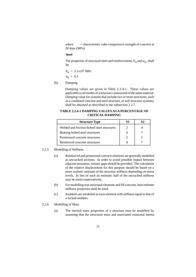
(b) Damping
Damping values are given in Table 2.2.4-1. These values areapplicable to all modes of a structure constructed of the same material.Damping value for systems that include two or more structures, suchas a combined concrete and steel structure, or soil-structure systems,shall be obtained as described in the subsection 2.2.7.
TABLE 2.2.4-1 DAMPING VALUES AS A PERCENTAGE OFCRITICAL DAMPING
Structure Type S1 S2
Welded and friction-bolted steel structures 2 4
Bearing-bolted steel structures 4 7
Prestressed concrete structures 2 5
Reinforced concrete structures 4 7
2.2.5 Modelling of Stiffness
(a) Reinforced and prestressed concrete elements are generally modelledas uncracked sections. In order to avoid possible impact betweenadjacent structures, seismic gaps should be provided. The calculationof the relative displacement for this purpose should be based on amore realistic estimate of the structure stiffness depending on stresslevels. In lieu of such an estimate, half of the uncracked stiffnessmay be used conservatively.
(b) For modelling non-structural elements and fill concrete, best estimatestiffness properties shall be used.
(c) Snubbers are modelled as truss element with stiffness equal to that ofa locked snubber.
2.2.6 Modelling of Mass
(a) The inertial mass properties of a structure may be modelled byassuming that the structural mass and associated rotational inertia
'ckf

12
are discretised and lumped at node points of the model. Alternatively,the consistent mass formulation may be used.
(b) In general, three translations and three rotational degrees of freedomshall be used at each node point. Some degrees of freedom, such asrotational, may be neglected, provided they do not affect the responsesignificantly. The following conditions shall be met:
(i) Structural mass shall be lumped so that the total mass as wellas the centre of gravity is preserved, both for the total structureand for any of its major components that respond in thedirection of motion.
(ii) The number of dynamic degrees of freedom, and hence thenumber of lumped masses, shall be selected so that allsignificant vibration modes of the structure can be evaluated.For a structure with distributed mass, the number of degreesof freedom in a given direction shall be equal to at least twicethe number of significant modes in that direction.
(c) The inertial properties shall include all tributary mass expected to bepresent at the time of the earthquake. This mass will include forexample, the effects of dead load, stationary equipment, piping andthe appropriate part of the live load.
(d) Building Model Hydrodynamic Mass Effects
For basins with walls that respond as a rigid body (i.e. fundamentalfrequency > frequency at ZPA) or for walls without local stressconcentrations, the entire horizontal impulsive mass may be locatedat a single height in the model. Similarly, the sloshing mass andassociated horizontal spring constant may be located at a single height.The magnitudes and locations along the height of the structure forthe masses and convective mode spring constants shall be determinedon the basis of engineering mechanics principles. When the basinwalls do not respond as a rigid body or when local stresses are ofinterest, the masses and associated sloshing mode horizontal springsshall be distributed over part of the basin wall height. Guidelines forcalculating spring constants, masses and locations of masses forrectangular basins are given in Appendix 1.
2.2.7 Modelling of Damping
(a) Modal Damping
When modal analysis is to be performed for structures with only onetype of material (hence single value of damping), the damping valuesgiven in Table 2.2.4-1 can directly be used for modal damping. Forstructural systems that consist of substructures with different damping
13
properties, the equivalent modal damping values may be obtainedusing strain energy equivalence.
(b) Proportional Damping (Rayleigh Damping)
When a damping matrix is required in a time history analysis, thedamping matrix [C] formed by a linear combination of the mass andstiffness matrices may be used :
(2.2)
where α and β are proportional damping coefficients and are givenby
(2.3)
where λ is the damping ratio from Table 2.2.4-1.
The two circular frequencies ω max and ω
min are the undamped circularfrequencies selected to define the range of frequencies, whichcontribute to the response of the structure.
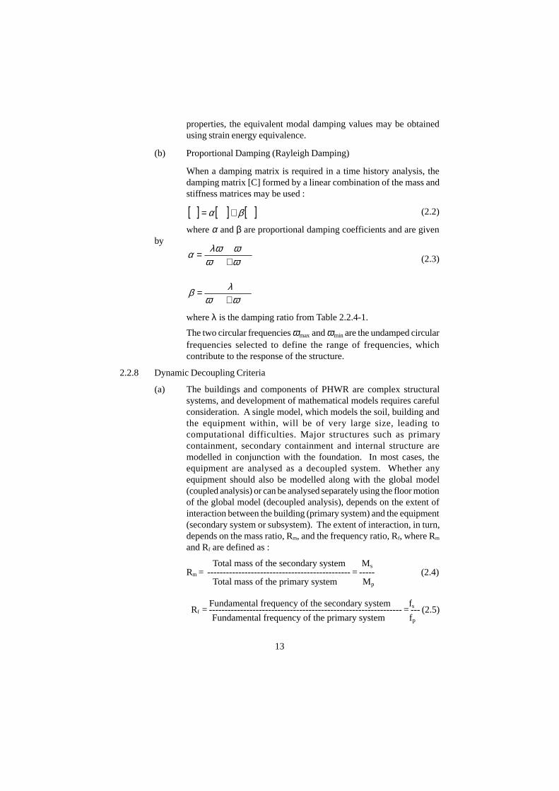
2.2.8 Dynamic Decoupling Criteria
(a) The buildings and components of PHWR are complex structuralsystems, and development of mathematical models requires carefulconsideration. A single model, which models the soil, building andthe equipment within, will be of very large size, leading tocomputational difficulties. Major structures such as primarycontainment, secondary containment and internal structure aremodelled in conjunction with the foundation. In most cases, theequipment are analysed as a decoupled system. Whether anyequipment should also be modelled along with the global model(coupled analysis) or can be analysed separately using the floor motionof the global model (decoupled analysis), depends on the extent ofinteraction between the building (primary system) and the equipment(secondary system or subsystem). The extent of interaction, in turn,depends on the mass ratio, Rm, and the frequency ratio, Rf, where Rm
and Rf are defined as :
Total mass of the secondary system MsRm = ---------------------------------------------- = ----- (2.4) Total mass of the primary system Mp
Fundamental frequency of the secondary system fsRf = -------------------------------------------------------------- = --- (2.5) Fundamental frequency of the primary system fp
[ ] [ ] [ ]KMC βα +=
minmax
minmax2
ωωωλωα
+=
minmax
2
ωωλβ+
=

14
If the primary and secondary systems consist of multiple modes, themass ratio (Rm) will be the modal mass ratio and the frequency ratio(Rf) will be based on the frequencies of these modes. All the modeswith modal mass > 20% shall be included.
(b) Following decoupling criteria shall be followed :
(i) If Rm < 0.01, decoupling can be done for any Rf
(ii) If 0.01 < Rm < 0.1, decoupling can be done ifRf < 0.8 or Rf > 1.25,
Coupling should be done if 0.8 < Rf < 1.25
(iii) If R m > 0.1, and Rf > 3.0, (i.e. the secondary system is rigidcompared to the primary system), it is sufficient to includeonly the mass of the subsystem.
(iv) If Rm > 0.1, and Rf < 0.33, (i.e. the secondary system isflexible compared to the primary system), decoupling can bedone.
(v) If Rm > 0.1, and 0.33 < Rf < 3.0, coupling is required.
(c) The above decoupling criteria are applicable for secondary systemswith single point attachment to the primary system. When thesecondary system has multiple attachments, the secondary systemmay restrict the movement of the primary system and may change itsfrequency. Multi-supported equipment should be reviewed for thispossibility, and the criteria of decompling should be based on ASCE4-98, C3.1.7.3.
2.3 Analysis of Structures
2.3.1 General Requirements
(a) Any one of the following three analysis methods, described in thissection, is acceptable for use in seismic response analysis.
(i) The time-history method (see sec. 2.3.2).
(ii) The response-spectrum method (see sec. 2.3.3)
(iii) The equivalent-static method (see sec. 2.3.4)
(b) Seismic analysis shall be performed for the three orthogonal (twohorizontal and one vertical) components of earthquake motion inaccordance with sec. 2.3.6. The orthogonal axes shall, in general, bealigned with the principal axes of the structure.
(c) Generally, floor systems in building structures of NPP have high in-plane rigidity. Advantage of rigid in-plane floors may be taken in
15
reducing number of degrees of freedom in the mathematical modelof the building. But out-of-plane flexibility of the floor systems shallbe considered for vertical motion. The model of a structure with non-rigid floors shall include the flexibility of the floor system.
2.3.2 Time-History Method
(a) General Requirements
(i) When more than one set of histories are used for input at thesame support in either linear or non-linear analyses, theresulting responses shall be averaged.
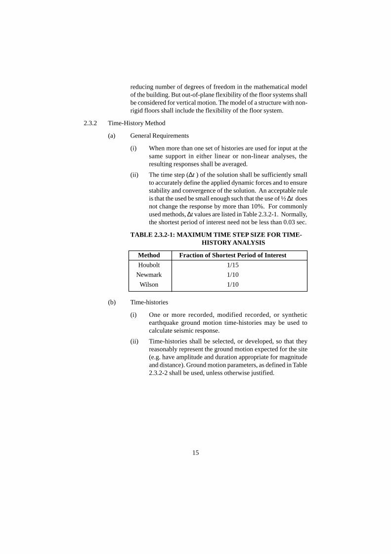
(ii) The time step (∆t ) of the solution shall be sufficiently smallto accurately define the applied dynamic forces and to ensurestability and convergence of the solution. An acceptable ruleis that the used be small enough such that the use of ½ ∆t doesnot change the response by more than 10%. For commonlyused methods, ∆t values are listed in Table 2.3.2-1. Normally,the shortest period of interest need not be less than 0.03 sec.
TABLE 2.3.2-1: MAXIMUM TIME STEP SIZE FOR TIME- HISTORY ANALYSIS
Method Fraction of Shortest Period of Interest
Houbolt 1/15
Newmark 1/10
Wilson 1/10
(b) Time-histories
(i) One or more recorded, modified recorded, or syntheticearthquake ground motion time-histories may be used tocalculate seismic response.
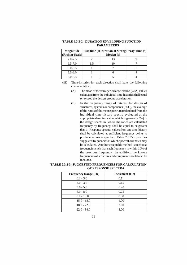
(ii) Time-histories shall be selected, or developed, so that theyreasonably represent the ground motion expected for the site(e.g. have amplitude and duration appropriate for magnitudeand distance). Ground motion parameters, as defined in Table2.3.2-2 shall be used, unless otherwise justified.
16
TABLE 2.3.2-2 : DURATION ENVELOPING FUNCTION PARAMETERS
Magnitude Rise time (s) Duration of Strong Decay Time (s)(Richter Scale) Motion (s)
7.0-7.5 2 13 9
6.5-7.0 1.5 10 7
6.0-6.5 1 7 5
5.5-6.0 1 6 4
5.0-5.5 1 5 4
(iii) Time-histories for each direction shall have the followingcharacteristics :
(A) The mean of the zero-period acceleration (ZPA) valuescalculated from the individual time-histories shall equalor exceed the design ground acceleration.
(B) In the frequency range of interest for design ofstructures, systems or components (SSC), the averageof the ratios of the mean spectrum (calculated from theindividual time-history spectra evaluated at theappropriate damping value, which is generally 5%) tothe design spectrum, where the ratios are calculatedfrequency by frequency, shall be equal to or greaterthan 1. Response spectral values from any time-historyshall be calculated at sufficient frequency points toproduce accurate spectra. Table 2.3.2-3 providessuggested frequencies at which spectral ordinates maybe calculated. Another acceptable method is to choosefrequencies such that each frequency is within 10% ofthe previous frequency. In addition, the knownfrequencies of structure and equipment should also beincluded.
TABLE 2.3.2-3: SUGGESTED FREQUENCIES FOR CALCULATION OF RESPONSE SPECTRA
Frequency Range (Hz) Increment (Hz)0.2 - 3.0 0.1
3.0 - 3.6 0.15
3.6 - 5.0 0.20
5.0 - 8.0 0.25
8.0 - 15.0 0.50
15.0 - 18.0 1.00
18.0 - 22.0 2.00
22.0 - 34.0 3.00
17
(C) Not more than 5 ratios shall be less than 1 and no onepoint of the mean spectrum (from the time-histories)shall be more than 10% below the design spectrum.
(D) Baseline of the time-history thus generated should becorrected such that the consequent ground velocity anddisplacement do decay realistically at the end of theduration.
(iv) When responses from the three components of motion arecalculated simultaneously, the input motion in the threeorthogonal directions shall be statistically independent, andthe time-histories shall be different. Shifting the starting timeof a single time-history does not constitute the establishmentof a different time-history. Two time-histories shall beconsidered statistically independent if the absolute value ofthe correlation coefficient does not exceed 0.3.
(c) Linear Method
(i) The response of a multi-degree-of-freedom linear systemsubjected to seismic excitation can be calculated using themodal superposition or direct integration time-history methods.
(ii) Modal-superposition
The modal-superposition method uses decoupled equation ofmotion for each mode.
• It shall be sufficient to include all the modes in theanalysis having frequencies less than the ZPAfrequency, provided that the residual rigid response dueto the missing mass is calculated and combinedalgebraically with the response of modes up to ZPAfrequency.
• Alternatively, the number of modes included in theanalysis shall be sufficient to ensure at least 90 % massparticipation. In this case, if the cutoff frequency isless than 33 Hz, missing mass correction correspondingto spectral acceleration (Sa) value at the cutofffrequency shall be applied.
(iii) Direct Integration
The equations of motion can be directly integrated. Eitherimplicit or explicit methods of numerical integration may beused to solve the equations of motion.
18
(d) Non-linear Methods
(i) When performing a non-linear analysis, the following shallbe considered:
Geometric non-linearity that significantly alter the effectivesystem geometry, such as large displacements or significantgaps;
Material non-linearity, such as plasticity or friction, in the rangeof response under consideration.
(ii) The direct integration and modal-superposition procedures(when appropriate) are acceptable methods to use for solution.
(iii) Non-linear analyses, shall, in general, consider all threecomponents of earthquake motion, which shall be consideredto act simultaneously unless it can be shown that individualcomponent responses are uncoupled.
(iv) In general, more than one set of acceleration time-histories,meeting the requirements of section 2.3.2(b) should be used,and the results of the analyses shall be averaged.
2.3.3 Response-Spectrum Method
(a) Linear Methods
(i) When the response-spectrum method is used, the generalisedresponse of each mode is determined from modal participationfactor, modal frequency, spectral acceleration and mode shapevector.
(ii) It shall be sufficient to include all the modes in the analysishaving frequencies less than the ZPA frequency provided thatthe residual rigid response due to the missing mass is added.
Alternatively, the number of modes included in the analysisshall be sufficient to ensure at least 90% mass participation.In this case, if the cutoff frequency is less than 33 Hz, missingmass correction corresponding to Sa value at the cutofffrequency shall be applied.
(iii) For modal combination purposes the residual rigid responseshall be considered as an additional mode having a frequencyequal to the ZPA.
(iv) Individual modal and component responses shall be combinedin accordance with the requirements of section 2.3.5 andsection 2.3.6 respectively.

19
(b) Non-linear Methods
When structures undergo inelastic response, a common means ofexpressing response is in terms of the displacement ductility ratio,which is defined as the ratio of maximum absolute relativedisplacement to its yield displacement. For the same input excitation,a non-linear response spectrum is lower than a linear responsespectrum. Because ductile structures can exhibit acceptableperformance during limited energy earthquake ground motion, thenon-linear response spectrum is used as a basis for establishing designseismic forces. The design approach is to determine seismic responseby using non-linear response spectrum corresponding to a limitedamount of ductility and compare that response to structural capacities.Values of ductility may be selected based on testing and pastobservations of earthquake damage which correspond to acceptableseismic behaviour of the structure. Larger values may be used formore ductile structures and values at or near unity may be used forbrittle or less ductile structures.
The response-spectrum method cannot be applied in a rigorous mannerto non-linear multi-degree of freedom systems because superpositionof modes is no longer valid. Therefore the use of inelastic responsespectra is restricted to structures, which behave as a single degree offreedom system.
2.3.4 Equivalent-Static Method
The equivalent-static method is a simplified method, as compared to othermore rigorous analysis methods presented elsewhere in this standard and canbe used for certain simple structures.
(a) Cantilever Models with Uniform Mass Distribution
(i) The equivalent static load base shear shall be determined forthese models by multiplying the cantilevered structure,equipment, or component masses by an acceleration equal tothe peak of the input response spectrum.
(ii) The corresponding base moment shall be determined by usingan acceleration equal to 1.1 times the peak of the applicableresponse spectrum. The resulting load shall be applied at thestructure's center of gravity.
(iii) Acceleration values smaller than those given in (i) and (ii)above may be used, if justified. The floor ZPA may be used ifit is shown that the fundamental frequency is so high, typically33 Hz, that no dynamic amplification will occur.

(b) Other Simple Structures
For cantilevers with non-uniform mass distribution and other simplestructures in which the maximum response results from loads in thesame direction (i.e. no change of sign in mode shape as e.g. in apropped cantilever), the equivalent static load shall be determined bymultiplying the structure, equipment, or component masses by anacceleration equal to 1.5 times the peak acceleration of the applicableresponse spectrum. Smaller values may be used, if justified, or thefloor ZPA value may be used if it is shown that the fundamentalfrequency is so high, typically 33 Hz, that no dynamic amplificationwill occur.
(c) When the equivalent static method is applied to multiple point ofattachment models, the response from the inertial loads shall becombined with the responses obtained from relative motion betweenpoints of support.
2.3.5 Combination of Modal Responses
(a) Response-Spectrum Analysis : General Modal Combination Rule
(i) With No Closely Spaced Modes
In a response spectrum analysis, if the modes are not closelyspaced (two consecutive modes defined as closely spaced iftheir frequencies differ from each other by 10% or less of thelower frequency), the representative maximum value of aresponse (stress, strain, shear, moment, displacement) of agiven element of the structure subjected to a single spatialcomponent of a three component earthquake should beobtained by taking the square root of the sum of squares (SRSS)of corresponding maximum values in individual modes.
Mathematically, this can be expressed as :
(ii) With Closely Spaced Modes
If some or all of the modes are closely spaced, one of theacceptable methods of modal combination is the GroupingMethod explained below :
Closely spaced modes should be divided into groups thatinclude all modes having frequencies lying between the lowestfrequency in the group and a frequency 10 percent higher.Groups should be formed starting from the lowest frequency
ÿ=i
2iRR
20

and working towards successively higher frequencies. No onefrequency is to be in more than one group.
The representative maximum value of a response attributedto each group should first be obtained by taking the sum ofabsolute values of the response of individual modes withinthat group. The representative maximum value of this responseattributed to all the modes should then be obtained by takingSRSS of corresponding maxima of each group and the maximaof the modes that are not closely spaced.
Mathematically, this can be expressed as :
(iii) Other methods such as double sum, ten percent or completequadratic combination are also acceptable.
2.3.6 Combination of Spatial Components
When responses from the three earthquake components are calculatedseparately, the combined earthquake-induced response shall be obtained by :
Where, R is any response of interest and R i (i = 1, 2 and 3) is obtained fromsec. 2.3.5 for the two horizontal components and one vertical component ofearthquake motion.
Alternatively, the responses may be combined directly, using the assumptionthat, when the maximum response from one component occurs, the responsesfrom the other two components are 40% of the maximum.
In this method, all possible combinations of the three components, R1, R2,and R3, including variations in sign shall be evaluated.
R = [R1 0.4R2 0.4R3]O R
R = [R2 0.4R3 0.4R1]O R
R = [R3 0.4R1 0.4R2]
These rules for combining responses apply to responses in the same directiondue to different components of motion.
2.3.7 Combination of Spatial Components for Time-History Analysis
(a) In a linear time-history analysis, the analysis may be performedseparately for each of the three components of earthquake motion, or
ÿ=k
2kRR
ÿ±=i
2iRR
21
+ +
+ +
+ +
one analysis may be performed by applying all three componentssimultaneously if the three components of earthquake motion arestatistically independent. When the analysis is performed by applyingall three components simultaneously, the responses are alreadycombined.
(b) When the analysis is performed separately for each spatial componentand three components of earthquake motion are statisticallyindependent, time-history responses for each of the three independentcomponents are combined algebraically at each time step to obtainthe combined response time-history.
(c) When linear time-history analyses are performed separately for eachcomponent, and three components of earthquake motion are notstatistically independent, the combined response for all threecomponents may be obtained using the SRSS rule to combine themaximum responses from each earthquake component :
Alternatively, the responses can be combined using the 100:40:40rule explained in sec. 2.3.6.
(d) In a non-linear analysis, the three components of earthquake motionshall be applied simultaneously to the system, consistent with therequirements of sec. 2.3.2, unless it can be shown that the responsefor one or more of the earthquake motion components can bedetermined independently.
2.4 Soil-structure Interaction - Modelling and Analysis
2.4.1 General Requirements
(a) Soil-structure interaction (SSI) effects shall be considered for allstructures not supported by a rock or rock like soil foundation material.
(b) The two acceptable methods of SSI analysis are the direct method,and the impedance function approach. Requirements for these aregiven in sec. 2.4.3 and 2.4.4 respectively.
(c) A fixed-base condition may be assumed when the soil behaves in arock-like manner. In general, a shear waves velocity of 1100 m/s orgreater warrants a fixed-base analysis. A fixed-base support mayalso be assumed in modelling structures for seismic response analysiswhen the frequency obtained assuming a rigid structure supported onsoil springs representing the soil supporting medium, established based
ÿ=i
i tt )(R)R(
ÿ±=i
i2RR
22
on Tables 2.4.4-1, 2.4.4-2, is more than twice the dominant frequencyobtained from a fixed base analysis of the flexible structurerepresentation. This frequency check should also be performed forstructures with stiff shear walls even when the shear wave velocity isgreater than 1100 m/s.
When the soil properties vary along the depth, the values to be usedin the analysis are those obtained from a weighted average over thefooting influence depth. The weighing factors for this purpose shallbe based on the influence zone of the footing in terms of stress levels(i.e. the soil pressure bulb below the footing) and the influence depthshall correspond to the level at which the stress intensity value is notgreater than 10% of the initial value in the immediate vicinity of thefooting. The values thus derived may be considered as the bestestimate value for the purpose of range analysis as per 2.4.1(f).
(d) Adjacent structures on the same foundation should be modelled inthe same model. Otherwise, absence of structure-to-structureinteraction should be demonstrated.
(e) The effect of mat flexibility for mat foundations and the effect ofwall flexibility for embedded walls need not be considered in the SSIanalysis performed to establish seismic responses.
(f) The uncertainties in the SSI analysis shall be considered. In lieu of aprobabilistic evaluation of uncertainties, an acceptable method toaccount for uncertainties in SSI analysis is to vary the low strain soilshear modulus. Low strain soil shear modulus shall be varied betweenthe best estimate value times (1 + Cv) and the best estimate valuedivided by (1 + Cv), where Cv is a factor that accounts for uncertaintiesin the SSI analysis and soil properties. If sufficient, adequate soilinvestigation data are available, the mean and standard deviation ofthe low strain shear modulus shall be established for every soil layer.The Cv shall then be established so that it will cover the mean plus orminus one standard deviation for every layer. The minimum value ofCv shall be 0.5. When insufficient data are available to addressuncertainties in soil properties, Cv shall be taken as no less than 1.0.
(g) Structural models defined in sec. 2.2 may be simplified for the SSIanalysis. Simplified models may be used provided they adequatelyrepresent the mass and stiffness effects of the structure and adequatelymatch the dominant frequencies, related mode shapes, andparticipation factors of the more detailed structure model.
(h) When a simplified model is used to generate floor response spectra,representative floor response spectra also shall be adequately matchedfor fixed-base conditions in both the detailed and simplified models.
23
(i) The potential for reduced lateral soil support of the structure shouldbe considered when accounting for embedment effects. One methodto address this concern is to assume no connectivity between structureand lateral soil over the upper half of the embedment or 6m, whicheveris less. However, full connection between the structure and lateralsoil elements may be assumed if adjacent structures founded at ahigher elevation produce a surcharge equivalent to at least 6m ofsoil. Another method to account for potential partial soil-structureseparation is soil property variation.
No credit may be taken for lateral support from back fill.
2.4.2 Subsurface Material Properties
Subsurface material properties shall be determined by field and laboratorytests supplemented as appropriate by experience, empirical relationships andpublished data for similar materials. The following material properties shallbe determined for use in equivalent linear analyses: shear modulus G; dampingratio λ ; Poisson's ratio υ , total unit weight γt , and modulus of subgrade reactionk. Material (hysteretic) damping in soil depends on the strain level. At lowstrains (< 10 - 4 %) the material damping ratio shall not exceed 2% of critical.
2.4.3 Direct Method
(a) SSI analysis by the direct method is performed in time domain andconsists of the following steps :
(i) Locate the bottom and lateral boundaries of the soil-structuremodel.
(ii) Establish input motion to be applied at the boundaries.
(b) Lower Boundary
The lower boundary shall be located for enough from the structurethat the seismic response at points of interest is not significantlyaffected. The lower boundary of the model may be placed at a layerat which the shear wave velocity equals or exceeds 1,100 m/sec or ata soil layer that has a modulus at least 10 times the modulus of thelayer immediately below the structure foundation level. The lowerboundaries need not be placed more than 3 times the maximumfoundation dimension below the foundation. The lower boundary maybe assumed to be rigid.
(c) Lateral Boundaries
The location of lateral boundaries shall be selected such that the effectof the waves reflected by the boundary is relatively small when
24
reaching the structure and, thus, does not significantly affect thestructural response at points of interest. Generally the response isproperly evaluated if the model's boundary is set at a distance of 2.5times the maximum foundation dimension from the building centre.Viscous or transmitting boundaries may be used to perform the SSIanalysis.
(d) Seismic Input for Model Boundaries
Seismic input motion is normally defined in the free field at the surfaceof the ground (finished grade). In this case, the seismic input is neededat the level of the lower boundary. This is obtained from the basicearthquake motion defined at the finished grade of the site by a de-convolution analysis. Use of free field motion at lower boundary isgenerally conservative and acceptable [7].
(e) Time Step
For solution of the SSI analysis in the time domain, the integrationtime step shall be selected to be small enough (1/10 of the smallestperiod) to ensure accuracy and stability of the solution.
2.4.4 Impedance Method
(a) SSI analysis by the impedance function approach shall consist of thefollowing steps :
(i) Determine the input motion to the mass-less rigid foundation.
(ii) Determine the foundation impedance functions.
(iii) Analyse the coupled soil structure system.
(b) Determination of Input Motion
The control motion defined at the free-field surface may be input tothe mass-less rigid foundation.
(c) Determination of Foundation Impedance Functions
(i) Equivalent Foundation Dimensions
For impedance function calculations all mat foundations maybe approximated by equivalent rectangular or circular shapes.The equivalent rectangular or circular dimensions shall becomputed by equating basement soil contact area fortranslational modes of excitation. The equivalent embedmentdepth shall be determined by equating volumes of soildisplaced by the embedded structure.
25
(ii) Uniform Soil Sites
When the soil below the foundation basement is relativelyuniform to a depth equal to the largest foundation dimension,frequency-independent soil spring and dashpot constants, asgiven in Appendix-2 (Table-1 for circular foundations andTable 2 for rectangular foundations), may be used.
(iii) Layered Soil Sites
Where the soil deposit can be approximated by a number ofhorizontal layers of uniform soil or where the uniform soildeposit is underlain by bedrock at a depth less than the largestequivalent foundation dimensions, frequency dependentimpedance functions shall be developed. An integral equationformulation is acceptable for computing the impedancefunctions. The use of finite-element or finite-differenceformulations is also acceptable.
(iv) Embedded Foundations
• For shallow embedments (depth-to-equivalent-radiusratio less than 0.3), the effect of embedment may beneglected in obtaining the impedance functions,provided the soil profile and properties below thebasemat elevation are used for the impedancecalculations.
• When the effect of embedment is considered, asimplified formulation may be used that assumes thatthe soil reactions at the base of the foundation are equalto those of a foundation placed on the soil surfaceassumed at the foundation elevation and uses lateralsoil reactions calculated independently using soilproperties of the side soil. There are several simplifiedmethods available for calculating these springs anddetermining where to place them. More accurateformulations using integral equations, finite-elementmethods, finite-difference methods, or a combinationof these methods may also be used.
(d) Analysis of Coupled Soil-Structural System
(i) The coupled soil-structure system shall include the structure,or its modal representation, and the soil spring and dashpotsanchored at the foundation level. The dynamic characteristicsof the soil shall be defined by impedance functions computed
26
in accordance with 2.4.4(c). The coupled soil-structure modelshall be analysed for input motions as required in 2.4.4(b).
(ii) Following procedures may be used:
• Direct integration time history method in which theenergy dissipation associated with the structure isincluded with the structural elements and the portionassociated with the soil is included with the soilelements.
• Modal time history or modal response spectrummethods using composite modal damping values.
2.4.5 Uplift Analysis of Foundation
When tensile force created by the seismic bending moment becomes equal tothe compressive force due to vertical load, the foundation mat will be subjectedto uplift. A detailed nonlinear analysis can calculate the amount of uplift andthe effect of this on stresses in the raft. However, this is a very complexprocess and it is desirable to have an approximate but conservative estimateand acceptance criterion. One such method (derived for rectangular rafts andapplicable to circular rafts with some approximation) is given below :
The condition of uplift is translated into the following equation:
Mo = NL/6
Mo = Bending moment at initiation of uplift
N = Total vertical load due to dead weight
L = Linear dimension of foundation in plan along the direction of motion
Uplift increases with increasing bending moment and the contact ratiodecreases.
Contact ratio = D/L = ½ (3 - M/Mo)
These formulas are derived for an infinitely rigid raft but can be conservativelyapplied to a flexible raft.
A loss of contact less than 30% of the plan dimension (contact ratio > 0.7) isconsidered acceptable. Under the uplift condition, the raft will see additionalbending due to loss of support over a part of area. This shall be evaluated andthe raft design shall be checked for the same.
Additionally, if the uplift, as calculated by this formula, is seen to be morethan 30% of the raft dimension (i.e. contact ratio less than 0.7), a properlysubstantiated dynamic analysis can be done to get a realistic and less
27
conservative estimate of uplift. However, if using either method the uplift isseen to exceed 30% of the raft dimension, adequate measure to tie thefoundation has to be taken.
2.5 Generation of Input for Floor Mounted Equipment (Subsystem) Analysis
2.5.1 General Requirements
(a) For seismic analysis or testing of floor-mounted equipment, inputmotion at the support location is required. If the equipment does notsatisfy the decoupling criterion as given in 2.2.8, it would be modelledspecifically along with the building and this requirement would notarise. This section covers the generation of seismic input for allsystems and components that are not specifically modelled in themain building dynamic model i.e. they are decoupled and analysedseparately.
(b) Types of Seismic Input for Subsystem Analysis
Seismic input for decoupled subsystem analysis may consist of oneor more of the following at subsystem supports :
• Floor response spectra and minimum/maximum displacementsand related phase correlation.
• Floor acceleration time-histories and displacement time-histories.
(c) Direction and Locations for Floor Response Spectra or Time-histories
Translational spectra or time-history inputs in each of the twoorthogonal horizontal directions and the vertical direction shall beprovided at reference locations where input motion to sub-systems isrequired. A reference location is normally a mass point of the buildingmodel. In a stick model, the reference location or the mass point is atthe floor level. These translational spectra or time-histories shallconsider uncertainties as discussed in sec. 2.5.2(e) and 2.5.3(b), andeffects of overall floor rocking and torsional motions.
(d) Subsystem Input Away from Reference Location
The location at which particular equipment is supported does notalways coincide with the reference location. In that case, the inputmotion for the equipment has to be derived from the motion at thereference location.
(e) In the case of a time-history analysis of a soil-structure systemsubjected simultaneously or individually to the action of threestatistically independent spatial components of an earthquake, the
28
resultant translational time histories at subsystem support locationsaway from the reference location may be obtained by algebraicsummation of the translational acceleration time-histories at referencelocation and the time-history contributions arising from the structuralrocking and torsional efforts, as long as the intervening structurebetween the two locations is rigid. The resultant translational timehistories thus obtained may then be used to generate the correspondingspectra.
(f) When the in-plane or transverse flexibility of the intervening structureis significant, the intervening structure shall be included in thesubsystem model to analyse the subsystem response. Alternatively,subsystem seismic input spectra and/or time-histories at subsystemsupport locations may be generated either by using a detaileddecoupled model of the flexible intervening structure if the decouplingcriteria are met, or by including the flexible intervening structure inthe main building system model.
(g) Floor Displacements and Rotations
Minimum/maximum translational displacements and rotations ordisplacement and rotational time-histories, if significant, shall bespecified to determine the effects of relative seismic displacements(Seismic Anchor Movements). The locations and directions for thesedisplacements and rotations shall be the same as those for the floorresponse spectra or time-histories.
2.5.2 Floor Response Spectra
(a) Floor response spectra shall be developed using the time-historymethod or by a direct spectra-to-spectra method.
(b) Time-History Method
(i) When the simultaneous action of three statistically independentspatial components of an earthquake is considered, the twohorizontal translational components and one verticaltranslational component of the time-history accelerationresponses at the reference location shall be used to computethe corresponding response spectra.
(ii) When the supporting soil-structure system is subjectedindividually to the action of the three statistically independentspatial components of the earthquake, the resultant time-historyat the reference location is obtained by the algebraic summationof the individual responses.
(iii) When time-history analysis of the supporting soil-structure
29
system is performed individually for each of two horizontalspatial components and one vertical spatial component of anearthquake, and the spatial components of the earthquake havenot been shown to be statistically independent, the timehistories from each individual analysis shall be used to generateresponse spectra at reference locations. The combinedresponse spectra shall be obtained by combining thecodirectional spectra amplitudes from three individual analysesusing the SRSS rule.
(iv) When more than one statistically independent time-historiesare used in a given direction, the floor response spectrum shallbe the average of all the spectra corresponding to the differenttime-histories. When three statistically independent time-histories (a, b, c) have been generated for the three spatialcomponents, this set of three time-histories can be used togenerate three different responses in a given direction by usingthe combinations (a, b, c), (b, c, a) and (c, a, b) in x, y and zdirections respectively.
(c) Direct Spectra to Spectra Method
(i) Direct spectra to spectra generation techniques may be usedwithin the framework of their established range of applicability.
(ii) This method may be adopted only for initial evaluationpurpose, which shall be backed up by rigorous analysissubsequently.
(iii) When the response spectrum at a given location and in a givendirection has contributions from more than one spatialcomponent of earthquake, these contributions shall becombined by the SRSS rule.
(d) Frequency Interval for Generation of Floor Response Spectra
(i) When generating floor response spectra, the spectrumordinates shall be computed at sufficiently small frequencyintervals to produce accurate response spectra, includingsignificant peaks normally expected at the natural frequenciesof the supporting structures.
(ii) One acceptable method is to compute floor response spectraat frequencies listed in Table 2.3.2-3 and at all naturalfrequencies of the supporting structures within the frequencyrange of interest. Another acceptable method is to choose aset of frequencies such that each frequency is within 10% ofthe previous one and then add the natural frequencies of the
30
31
supporting structures to the set. Alternatively, a set offrequencies such that each frequency is within 5% of theprevious one may be chosen.
(iii) The frequency interval may be increased in the frequency rangeabove twice the dominant interaction frequency, or the cut-offfrequency.
(e) Treatment of Uncertainties in Generating Floor Response Spectra
(i) Floor response spectra shall account for uncertainties inresponse due to the uncertainties in supporting structurefrequencies and soil-structure interaction analysis.
(ii) One acceptable approach is peak broadening. The minimumbroadening shall be 15% at each frequency in the amplifiedresponse region for the best estimate soil shear modulus case.In some cases the spectral broadening from variation of soilshear modulus, as described in section 2.4.1, will control. Thefinal spectra shall envelop the upper and lower bounds on theshear modulus. In conjunction with response-spectrum peakbroadening, a 15% reduction in peak amplitude is permissibleprovided the subsystem damping is less than 10%.
(f) Interpolation of Floor Response Spectra for Intermediate Damping
Response Spectra for an intermediate damping value λ may begenerated from spectra for two adjacent damping values λ1 and λ2
provided : (i) λ1< λ < λ2 ≤ 3λ1 and (ii) the following relationshipbetween spectral amplitudes and damping is used for all frequencies:
where, S λ , S1, S2 = Spectral Amplitude associated with λ, λ1 and λ2
respectively.
The above procedures are to be used for interpolation and not forextrapolation.
2.5.3 Floor Time-History Motions
(a) Methods for Generation of Floor Time-History Motions
Time-histories of floor motion may be used for equipment analysisinstead of response spectra. Floor time-history response at thereference locations or subsystem support locations obtained from thetime-history analysis of the supporting soil-structure system may bespecified as input to singly or multiply-supported subsystems.
( ) ÿÿ�
����
�
−−
−+=−−
21
2122
21
22 SSSS
λλλλ
λ
λλ
32
(b) Equivalent Broadening and Lowering of Floor Time-History Motions
(i) As in sec. 2.5.2, the effect of uncertainties has to be consideredwhen time-histories of floor motions from the dynamic time-history analysis of the supporting soil-structure system areused. In this case, the frequency content of the time-historiesfrom the structural analysis shall be varied to be consistentwith the requirements of sec. 2.5.2.
(ii) An acceptable method to vary the frequency content of theFloor acceleration time-histories for best estimate soilproperties is by expanding and shrinking the time-historywithin 1/(1 0.15) so as to change the frequency content ofthe time history within 15%.
(iii) Additional variation of frequency content shall be employed,if required, to envelop the upper and lower bound soil propertycase responses.
(c) Time Interval and Data Precision Requirements for Floor Time-History Motions
Acceleration and displacement data shall be provided in accordancewith user requirements, which may be dependent on the subsystemanalysis techniques that are to be used. In lieu of specific requirements,the time interval between data points shall not exceed 0.01 sec andacceleration data precise to 0.001g and displacement data precise to0.0025 mm shall be provided.
2.5.4 Structural Model or Characteristics for Coupled Subsystem Analysis
(a) Equipment/piping (subsystem) satisfying the decoupling criteria (i.ethere is no interaction or only marginal interaction between thebuilding and the equipment) are analysed separately using a detailedstructural model and subjecting it to the response spectra or time-histories developed in sec. 2.5.2 and sec. 2.5.3 respectively.Uncertainties in modelling are taken into account by the concept ofbroadening.
(b) Sometimes even the non-interacting or marginally interactingsubsystems complying with the decoupling criteria are analysed aspart of a coupled model. A detailed analysis of the equipment is thenperformed using a detailed model of the equipment and a simplifiedmodel of the building (supporting structure). The input for this modelis the input motion at the base of the building. No intermediate floormotions are developed. In order to take into account the effect ofuncertainties in such cases, frequency shifting of the supportingstructure or the equipment, equivalent to the requirements of sec.
++
2.5.2 shall be applied to preclude possible underestimation ofequipment response.
(c) Equipment, which do not satisfy the decoupling criteria are analysedas part of the overall building model. A subsequent analysis of theequipment may use a detailed structural model of the equipment anda simplified model of the building, with excitation at its base. In suchcases, the frequency shifting as required in (b) above is unnecessary.
(d) The simplified model of the building shall be developed from adetailed model of the building in such a way that the significantfrequencies and mode shapes for the fixed-based detailed andsimplified models are reasonably matched at the equipment supportlocations. The adequacy of the simplified model shall be establishedby a comparison of the floor spectra at equipment support locationsin the fixed-base detailed and simplified models.
(e) The base excitation to be used in the detailed equipment analysisshall include the effects of soil-structure interaction, and shall beprovided at the base of the supporting structure in the form oftranslational acceleration and displacement time-histories and/orresponse spectra in three orthogonal directions.
2.6 Design of Buildings/Structures
(a) Design Check
The seismic forces and moments calculated as per the guidelines inthis chapter shall be combined with the forces and moments due toother loadings in appropriate load combinations and the structure bedesigned as per AERB Safety Standard, AERB/SS/CSE [4] andassociated Civil and Structural Engineering Standards for differentstructures.
33

3. SEISMIC QUALIFICATION OF EQUIPMENT
3.1 General
The equipment in NPP are designed for various loads viz.:
• Load during design, normal and upset conditions (pressure,temperature, mechanical, cycles, transients); and
• Loads during emergency and faulted conditions (pressure, mechanicaltest load etc. as applicable) including natural phenomenon likeearthquake.
In most of the equipment used in a nuclear plant, the thickness based on pressureloading is adequate for resisting seismic loading also. Therefore, seismicdesign essentially involves design of the supports, which should be firmlyfixed to the supporting structure. A check on stresses resulting from loadcombinations involving seismic loads still needs to be carried out.
The seismic supports should be arranged in appropriate position and directionso that the thermal expansion of the equipment is restrained as little as possibleand there is no excessively large seismic response during an earthquake. If,on the other hand, the thermal expansion is restrained, it is important to confirmthat the thermal stresses of the system are within the allowable limit. For theequipment such as large size storage tanks, viz., demineralised water storagetank, fuel tank, the seismic support alone is not adequate. It is necessary toreinforce the earthquake strength of the equipment itself.
3.2 Classification
Depending on the safety function performed by the SSC, various equipmentof NPP are classified into three seismic categories as per AERB Safety GuideAERB/NPP-PHWR/SG/D-1. Seismic Category-1 equipment are required tobe qualified for both S1 (OBE) and S2 (SSE) earthquake. Seismic Category-2 equipment are required to be qualified for S1(OBE) earthquake and seismicCategory-3 equipment may be designed for earthquake resistance as per thenational practice for non-nuclear application.
3.3 Structure Equipment Interaction
In most cases, the mechanical and electrical equipment come under thedefinition of secondary system and are analysed or tested as a decoupled systemfrom the primary system. The seismic input for the equipment is obtained bythe analysis of the structure/building (Primary Structure) in which they arehoused. Their dynamic coupling to the main building can usually be neglected,provided they meet the general decoupling criteria, in subsection 2.2.8.
34

The decoupling criteria in sec. 2.2.8 utilise the fundamental frequencies ofthe structure and the equipment. In general, both the structure and theequipment are multi-degree of freedom systems. In such cases, the frequencyand mass ratios can be computed mode wise using the modal frequencies andmodal masses. Only the dominant modes need be considered. The number ofdominant modes can be identified as those in which modal mass is more than20% of the total mass.
3.3.1 Decoupling Criteria for Multi Supported Equipment
The decision to decouple the equipment from the building model may need tobe revised in case of multi-supported equipment, such as steam generatorsupported at many elevation of the reactor building. The criteria given inclause 3.1.7.3 of ASCE 4-98 [5] may be adopted for this purpose.
3.4 Equipment Stiffness and Mass Modelling
Seismic analysis of equipment generally uses finite element (FE) methods.Most of the standard, commercially available computer codes have thecapability to perform the analysis. In this case, modeling of stiffness andmass is relatively straightforward. One of the following techniques is adopted.
3.4.1 Beam Model or One-Dimensional Finite Element
This modeling is typically applied to beams, columns, frames, ducts, cabletrays, conduits, tanks, cabinets, storage racks, which are expressed as acontinuous or one dimensional finite element in a two or three- dimensionalspace. Masses are represented by lumped parameters, which develop adiagonalised elemental mass matrix. Pressure vessels and heat exchangerscan also be modelled this way, especially when using the equivalent staticmethod. For the equipment, which has sections of irregular shapes, a beammodel of this equipment is generated using energy equivalence between plateor shell type finite element model and beam model.
3.4.2 Plate/Shell Finite Element
This type of modeling is adopted for items whose primary mode of failure isby biaxial bending stress, plane stress or plane strain. Typically included inthis category are : cabinets, tanks, pressure vessels and heat exchangers whoseshells support significant eccentric loads which would tend to excite shell orlocal modes of vibration.
3.4.3 Solid Finite Element
In this, the equipment is modeled using solid elements. This type of modelingis expensive and is preferable for local analysis to obtain correct stress pictureat openings, nozzle junctions etc.
35
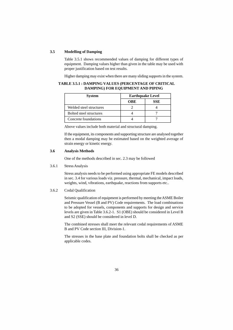
3.5 Modelling of Damping
Table 3.5.1 shows recommended values of damping for different types ofequipment. Damping values higher than given in the table may be used withproper justification based on test results.
Higher damping may exist when there are many sliding supports in the system.
TABLE 3.5.1 : DAMPING VALUES (PERCENTAGE OF CRITICALDAMPING) FOR EQUIPMENT AND PIPING
System Earthquake Level
OBE SSE
Welded steel structures 2 4
Bolted steel structures 4 7
Concrete foundations 4 7
Above values include both material and structural damping.
If the equipment, its components and supporting structure are analysed togetherthen a modal damping may be estimated based on the weighted average ofstrain energy or kinetic energy.
3.6 Analysis Methods
One of the methods described in sec. 2.3 may be followed
3.6.1 Stress Analysis
Stress analysis needs to be performed using appropriate FE models describedin sec. 3.4 for various loads viz. pressure, thermal, mechanical, impact loads,weights, wind, vibrations, earthquake, reactions from supports etc..
3.6.2 Codal Qualification
Seismic qualification of equipment is performed by meeting the ASME Boilerand Pressure Vessel (B and PV) Code requirements. The load combinationsto be adopted for vessels, components and supports for design and servicelevels are given in Table 3.6.2-1. S1 (OBE) should be considered in Level Band S2 (SSE) should be considered in level D.
The combined stresses shall meet the relevant codal requirements of ASMEB and PV Code section III, Division-1.
The stresses in the base plate and foundation bolts shall be checked as perapplicable codes.
36
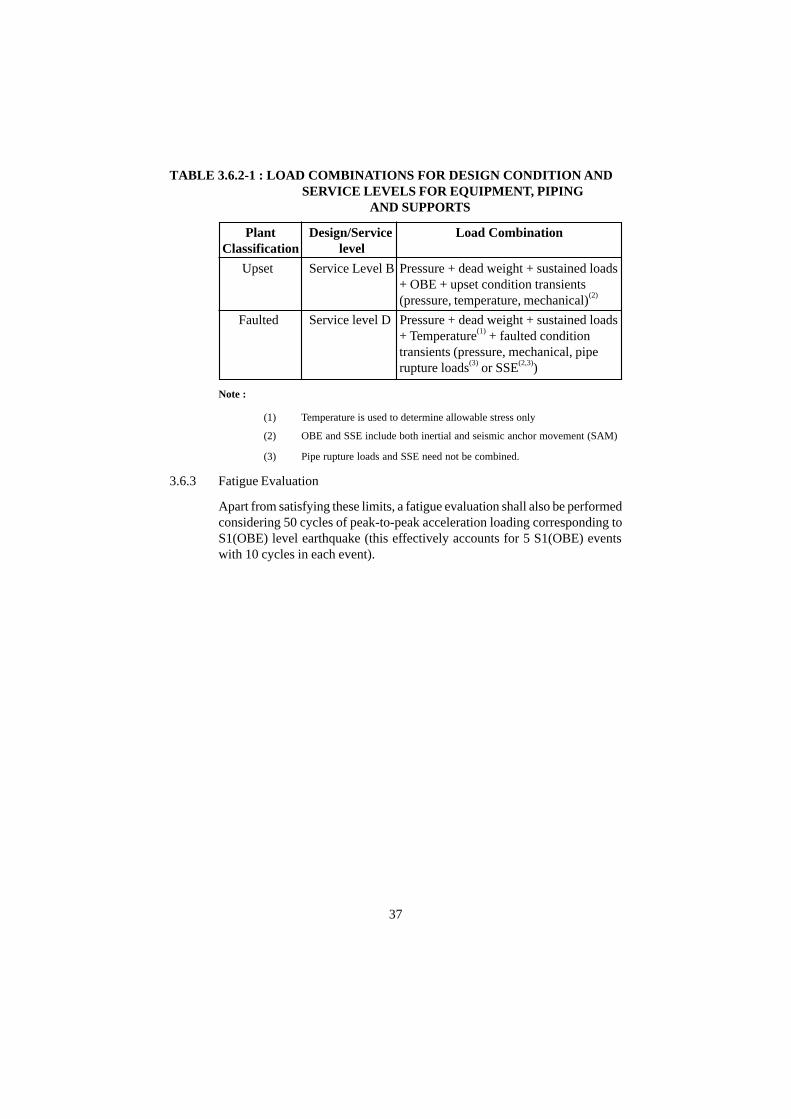
TABLE 3.6.2-1 : LOAD COMBINATIONS FOR DESIGN CONDITION ANDSERVICE LEVELS FOR EQUIPMENT, PIPING
AND SUPPORTS
Plant Design/Service Load CombinationClassification level
Upset Service Level B Pressure + dead weight + sustained loads+ OBE + upset condition transients(pressure, temperature, mechanical)(2)
Faulted Service level D Pressure + dead weight + sustained loads+ Temperature(1) + faulted conditiontransients (pressure, mechanical, piperupture loads(3) or SSE(2,3))
Note :
(1) Temperature is used to determine allowable stress only
(2) OBE and SSE include both inertial and seismic anchor movement (SAM)
(3) Pipe rupture loads and SSE need not be combined.
3.6.3 Fatigue Evaluation
Apart from satisfying these limits, a fatigue evaluation shall also be performedconsidering 50 cycles of peak-to-peak acceleration loading corresponding toS1(OBE) level earthquake (this effectively accounts for 5 S1(OBE) eventswith 10 cycles in each event).
37

4. SEISMIC QUALIFICATION OF PIPING
4.1 General
There is an essential difference between the design of equipment and piping.The piping needs to be rigid enough to resist seismic loading. But, at thesame time, extra rigidity is also harmful as it will hamper its ability to absorbthermal expansion.
4.2 Classification
NPP piping are classified into three seismic categories as per Design SafetyGuide AERB/SG/D-1. Seismic category-1 piping are those required to bequalified for S1(OBE) earthquake and S2 (SSE) earthquake. Seismiccategory-2 piping are required to be qualified for S1(OBE) earthquake. Seismiccategory-3 piping are designed for earthquake resistance as per the nationalpractice for non-nuclear application.
4.3 Structure-Equipment-Piping Interaction
The piping is normally analysed as an uncoupled system. For the uncoupledmodel, the input motion is required at the support points and is derived fromthe results of previous analysis of the supporting primary system.
It is also possible to analyse the piping along with a simplified model of theequipment. For the combined model, the input motion is the one at the baseof the supporting equipment.
However, if the piping is rigid and the decoupling criterion as given in sec.2.2.8 are not satisfied, it should be analysed along with the connected equipmentand supporting primary structure. This is done to account for the interactionbetween the supporting structure and the supported piping.
A branch pipe can be decoupled if the ratio of moment of inertia of the branchpipe to the moment of inertia of the run pipe is more than 20. If branch pipeis decoupled from run pipe, the displacements of the run pipe at the branch torun intersection shall be treated as Seismic Anchor Movement (SAM) forbranch pipe analysis. However, in this case, the branch pipe will be analysedusing the spectra generated at the point of intersection.
4.4 Mathematical Idealisation of Piping System
In most of the cases, mathematical idealisation of piping system is based onlinear elastic model, using 3-D line (beam or pipe) elements for idealisationof tangent pipe, bend/pipe elbows, tees, concentric/eccentric reducers, valves,pipe supports with mass or mass moment of inertia lumped at discrete nodalpoints.
38

In certain cases, 3-D continuum (shell) elements, 3-D solid elements may alsobe used for idealisation of piping system in linear elastic domains. This maybe restricted to equipment-piping junctions for obtaining local stresses.
Similarly, in some special cases, mathematical idealisation of piping systemcalls for a geometric and/or material non-linear model to account for non-linear pipe support stiffnesses, sizable gaps at pipe support etc.
4.4.1 Modelling of Stiffness
Mathematical idealisation of piping element and pipe support stiffness shouldbe in conformance with following principles :
(a) The piping is represented by a 3-D model with stiffnesses determinedby accounting for axial, shear, torsional and flexural forces.
(b) Requisite input values for evaluation of piping stiffness are: outsidediameter, pipe wall thickness, Young's modulus of elasticity andPoison's ratio. In additions to this, stiffness of safety class 1 pipebend/elbow is also influenced by internal pressure (ASME B and PVCode, section III, subsection NB).
(i) Nominal value of outside diameter is used.
(ii) Value of nominal wall thickness minus design corrosionallowance is used.
(iii) In principle, the values of Young's modulus used in the stiffnessevaluation of piping are those at the temperatures when theseismic motion is considered acting concurrently. Since, theprobaility of concurrent occurrence of a temperature transientand an earthquake is very small, the highest temperature ofthe piping in the normal operation may be used for evaluationof properties.
(iv) Similarly, the value of internal pressure used in the stiffnessevaluation of safety class 1 pipe bend/elbows is the normaloperating pressure.
(c) The pipe supports are idealised with following boundary conditions.
Restraint : The stiffness in the restraining direction is considered.Anchor : The stiffness for the six degrees of freedom are considered.Snubber : The stiffness in the restraining direction is considered.Spring Hanger : Stiffness is not considered.
4.4.2 Modelling of Mass
Mathematical idealisation of piping mass should be in conformance withfollowing principles.
39

(a) The nodal points in the piping model are set with an appropriatespacing to enable full representation of the typical vibration modesupto cut-off frequency.
(b) In addition to mass of piping itself, masses of fluid in pipes, massesof thermal insulation and concentrated masses of the valves and flangesare also taken into consideration.
(c) Extended mass of valves or other eccentric masses should be idealisedappropriately to account for the torsional effect associated with theeccentricity.
(d) For submerged pipe, the mass of the displaced water will be added tothe mass of the pipe.
4.4.3 Modelling of Damping
The damping value used in the analysis of piping shall be limited to 4% ofcritical damping for SSE and 3% of critical damping for OBE irrespective ofthe size of piping. This includes both material and structural damping [14].
As an alternative for response spectrum analyses using an envelope of theSSE or OBE response spectra at all support points (uniform support motion),frequency-dependent damping values given below may be used, subject tocertain restrictions stated subsequently [14] :
Freqency (Hz) Damping (% of critical)
upto 10 5
more than 10 but less linearly varying between 5 and 2than 20
20 and higher 2
The following restrictions apply for use of the alternative damping valuesstated above:
(a) Frequency-dependent damping should be used completely andconsistently, if at all.
(b) Use of the specified damping values is limited only to responsespectral analyses. Acceptance of the use of the specified dampingvalues with other types of dynamic analyses (e.g., time-history analysesor independent support motion method) requires further justification.
(c) When used for reconciliation or support optimisation of existingdesigns, the effects of increased motion on existing clearances andonline mounted equipment should be checked.
(d) Frequency-dependent damping is not appropriate for analysing thedynamic response of piping systems using supports designed todissipate energy by yielding.
40
(e) Frequency-dependent damping is not applicable to piping in whichstress corrosion cracking has occurred, unless a case-specificevaluation is provided and reviewed and found acceptable.
For specified seismic input motion, response of piping system is controlledby damping. Damping may be increased by using viscous dampers etc. Insuch cases energy dissipation capacity of viscous damper should be accountedappropriately in seismic analysis of piping system.
4.5 Dynamic Analysis Methods
4.5.1 Time-History Analysis
The Response Spectrum method (see sec. 4.5.2) is generally used for analysisof piping. This method is valid only for linear behaviour. When nonlinearitiesoccur due to nonlinear pipe support stiffness or due to sizeable gaps at supports,time history analysis is required for evaluation of dynamic response. It is alsorequired for generation of Required Response Spectrum (RRS) for seismictesting of safety related valves in linear piping systems, with three componentsof seismic motions acting concurrently.
Interpretation of vast amount of output data and cost factor prohibit the useof time-history analysis for linear piping systems. But in principle time-historyanalysis of linear piping system may be performed for some special cases.
The time-history used as input for the piping analysis is the floor time-historyderived from the analysis of the supporting structure. When the two ends ofthe piping are supported on the same floor, the input motion is the motion ofthat floor. In case of long pipes, if the two points on the same floor havedifferent motion, appropriately different motion shall be used in the analysis.In many cases, the piping is supported at two or more number of floors. Inthat case, appropriately different input motion has to be used at the differentsupports.
4.5.2 Response Spectrum Analysis
In general, the piping is supported at two or more number of floors. Responsespectra are determined for each support motion. The two methods of ResponseSpectrum Analysis with multiple support input are :
(a) Envelope Response Spectrum Method (or, uniform support motionmethod)
(b) Multiple Response Spectrum Method (or, independednt supportmotion method)
4.5.2.1 Envelope Response Spectrum Method
The response spectrum to be used in this method is the single response spectrum
41

that envelopes each of the relevant spectra at the support locations. Thisenvelope spectrum is used at all of the support locations.
Modal and component responses are combined as follows:
(a) Modal Combination : Depending on numerical values of naturalfrequencies, modes can be classified as far spaced modes or closelyspaced modes.
Responses should be combined by Square Root of Sum of Squares(SRSS) method for far spaced modes only.
For closely spaced modes, the responses should be combined by anyof the acceptable method as per RG 1.92, Revision 1, February 1976(Combining Modal Responses and Spatical Components in SeismicResponse Analyis) viz. ten percent method, double sum method,complete quadratic combination (CQC) etc.. In lieu of this, if on thebasis of study of all the mode shapes upto 33 Hz, it is demonstratedthat so called closely spaced modes excite the different segments/spans of piping system which are not the adjacent segments/spans,use of SRSS method is admissible for closely spaced modes also.
(b) Combination of Spatial Components - A modal combination shall befollowed by spatial combination. Directional responses should becombined by SRSS method.
4.5.2.2 Independent Support Motion RS Analysis
(a) By this technique, different supports are first separated into differentgroups, so that supports within a group are subjected to the samemotion. A single response spectrum is applied to a group of supports,but different input spectra are applied to different groups of supports.
(b) Modal combination is performed as per sec. 4.5.2.1(a).
(c) The contributions from each support within a group are algebraicallycombined, consistent with the assumption of same motion.
(d) To obtain the response due to input applied at all supports, individualgroup responses should be combined. When no phasing informationis available, they are combined using the Absolute Sum method. Thismethod is consistently conservative when compared with the exacttime history results.
However, sometimes it is excessively conservative.
(e) Algebraic combination of group responses is acceptable if it can beshown that responses of all supports are essentially in-phase.
(f) SRSS combination of individual grouped responses is acceptable if
42

it can be shown that each of the independent spectra are un-correlated.Since the primary system (structure/equipment) is common for allsupports, it leads to considerable phase correlation, and therefore,SRSS method should generally not be used.
(g) A modal combination shall be followed by spatial combination.Directional responses should be combined by SRSS method.
4.5.3 Rigid Body Response
In the analysis of piping systems, solution of eigen values problem is generallycarried out upto cut-off frequency. Dynamic rsponse due to modes havingnatural frequencies more than the cut-off frequency is called Rigid-BodyResponse or Missing Mass response. This should be added to the computedresponse using SRSS method.
4.5.4 Seismic Anchor Movement Analysis
Response calculated in 4.5.1, 4.5.2 and 4.5.3 is the inertial response of thepiping. Piping system supported from two or more number of floors in abuilding or between two buildings is also subjected to differential movementsduring seismic event. Experience of past earthquakes show that piping havefailed at a number of places due to seismic anchor movement because of lackof flexibility to account for differential movements. Therefore, seismic anchormovement should be properly accounted for. This is accomplished by a staticanalysis in which the relative movements at supports locations are specified.If phase information is available, relative movement will be the algebraicdifference between the support movements. If phase information is notavailable, the supports shall be assumed to move in opposite direction and therelative movement shall be the absolute sum of support movements.
Combination rules for seismic anchor movement analysis responses withinertial responses are as follows.
(a) Time-history Analysis :
At each time step, evaluate the seismic anchor movement and inertialresponse. Total response is obtained by algebric addition method.
(b) Response Spectrum Analysis :
Total response should be combined using SRSS method.
4.5.5 Simplified Dynamic Analysis
A simplified seismic load coefficient method as given in ASME B and PVCode, Section III, Appendix- N, may be used for calculating seismic inertiainduced piping stresses, displacements, loads and support reaction loads.
43
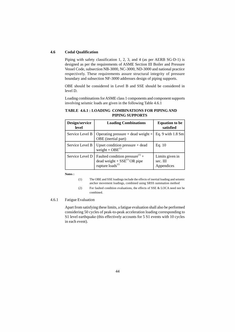
4.6 Codal Qualification
Piping with safety classification 1, 2, 3, and 4 (as per AERB SG-D-1) isdesigned as per the requirements of ASME Section III Boiler and PressureVessel Code, subsection NB-3000, NC-3000, ND-3000 and national practicerespectively. These requirements assure structural integrity of pressureboundary and subsection NF-3000 addresses design of piping supports.
OBE should be considered in Level B and SSE should be considered inlevel D.
Loading combinations for ASME class 1 components and component supportsinvolving seismic loads are given in the following Table 4.6.1
TABLE 4.6.1 : LOADING COMBINATIONS FOR PIPING AND PIPING SUPPORTS
Design/service Loading Combinations Equation to be level satisfied
Service Level B Operating pressure + dead weight + Eq. 9 with 1.8 SmOBE (inertial part)
Service Level B Upset condition pressure + dead Eq. 10weight + OBE(1)
Service Level D Faulted condition pressure(1) + Limits given indead weight + SSE(1) OR pipe sec. IIIrupture loads(2) Appendices
Notes :
(1) The OBE and SSE loadings include the effects of inertial loading and seismicanchor movement loadings, combined using SRSS summation method
(2) For faulted condition evaluations, the effects of SSE & LOCA need not be
combined.
4.6.1 Fatigue Evaluation
Apart from satisfying these limits, a fatigue evaluation shall also be performedconsidering 50 cycles of peak-to-peak acceleration loading corresponding toS1 level earthquake (this effectively accounts for 5 S1 events with 10 cyclesin each event).
44

5. SEISMIC QUALIFICATION BY TESTING
5.1 General
Many of the mechanical, electrical and instrumentation and control equipmentinvolve mechanical motion, and as such functional operability becomes anadditional qualification requirement along with structural and pressureboundary integrity as required for the structure and system respectively. Ingeneral, seismic test qualification program is recommended for equipment,which are having close gaps/clearances between moving components for theirfunctional performance, closure of these gaps/clearances can result into apossible malfunction jeopardising the functional operability of the equipment.
Active equipment viz. reactor control and shutdown devices; valves; rotatingequipment viz. pumps, fans, blowers, motors; reciprocating equipment viz.compressors, diesel generators, reciprocating pumps; panels having deviceslike relays, contactors, recorders, switches, beepers etc. performing amechanical motion and having close gaps/clearances between movingcomponents fall in this category.
The equipment like pumps, fans, blowers, motors; compressors, dieselgenerators, reciprocating pumps, have close gaps/clearances between themoving and stationary components. The components of these equipment viz.,shafts-bearings, impeller-casing, piston-cylinder, are large components andcan be modelled and analysed by finite element method to demonstrate theirfunctional operability based on deflection of the moving components duringseismic events to be within the allowable gaps/clearances, as well as bydemonstrating that the forces at the bearing location are less than the bearingdesign load. However, it may be noted here that even for these equipment,seismic qualification by testing is more reliable method to demonstrate theirfunctional operability.
Instrumentation and control and electrical panels have devices like relays,contactors, recorders, switches, beepers etc., which have very close gapsclearances and have complex geometries, uncommon materials making itdifficult to model and analyse. Valves also fall in the category of devices andequipment, which are complex in nature and cannot be modelled/analysed todemonstrate their functional operability, and have to be seismically qualifiedby testing. It is preferable to test the devices for their fragility so that thelimiting value for their operability is known and is required to be demonstratedto be less than the one to be seen by the device in a panel at plant for thedesigned earthquake motion.
In general, the seismic qualification test should be conducted by mounting theequipment on a shake table. While a seismic motion is given to the shake
45
table, the equipment should be checked for its intended functional operability.During the test, the operating conditions/loads of the equipment should alsobe simulated adequately. The test should conservatively simulate the seismicevent at the equipment mounting location. In particular, the multidirectionaland broadband nature of the seismic motion should be simulated.
Normally, the residual life of the equipment may not be significantly affecteddue to the shake table test, however, an equipment that has been shake tabletested should, in general, not be installed in a plant, unless it can bedemonstrated that accumulated stress cycles experienced by the equipmentduring the test will not degrade its ability to perform its intended function.
5.2 Equipment Seismic Test Qualification Specification
In order to meet the functional operability requirement of the equipment,various functions to be performed by many devices and sub-devices in theequipment and associated parameters, which are to be monitored during theshake table test shall be brought out in the equipment specification. Thesefunctions and associated parameters may include the timings of opening andclosing of valves; making and breaking of electrical contacts; relay positionand allowable chattering time, change of state during seismic transient;pressure, temperature, voltage, current, humidity, radiation and chemical andother load conditions/settings; characteristics of seals, gaskets and insulationand their functional requirements; the descriptions of complete operating cycleand number of operating cycles; duration and, ranges of operating loads;environmental aging requirements; and any other requirement peculiar tospecific equipment etc. as applicable and as given in the general specificationof the equipment.
5.3 Seismic Qualification Test Plan
The seismic qualification test plan generally includes the following elementsas applicable :
(a) Seismic loads;
(b) Input motion;
(c) Mounting;
(d) Concurrent loads;
(e) Monitoring;
(f) Refurbishment;
(g) Seismic qualification test; and
(h) Test acceptance criteria.
46
5.3.1 Seismic Loads
5.3.1.1 Required Response Spectrum
Generally, the seismic motion expected at the place of installation of equipmentin two horizontal and vertical directions are given in the form of requiredresponse spectra (RRS) in horizontal and vertical direction for 5% damping.For the equipment, which are mounted on floor, the applicable RRS are thefloor response spectra of the floor on which equipment is mounted. In casethe equipment is mounted on a wall, then the RRS is the envelope of the twofloors connected by the wall. The RRS shall be generated by 15% broadeningof the acceleration spectrum at all the frequency points of the responsespectrum. The duration of the test should be equal to duration of the strongmotion portion of the original time history. If the information on this is notavailable, the equipment should be tested for 30 seconds. If equipment isused on different floors of a plant building(s) then envelope of respectivefloor response spectra shall be used. The orientation of equipment with respectto two horizontal axes should be considered while giving two specifichorizontal spectra or envelope of both horizontal spectra shall be given ifequipment orientation is uncertain.
For the line-mounted equipment like valves or instruments mounted in panelsetc. the peak acceleration or acceleration time-history or the accelerationresponse spectrum seen by devices shall be analytically determined and shallbe used for seismic qualification testing of these devices.
If the supporting structure (piping, wall, panel or instrument support stand orpanel etc.) of the device (valve, instrument, actuator etc) is demonstrated tobe rigid i.e. natural frequency of the supporting structure being greater than orequal to 33 Hz, then floor response spectra may be used as RRS.
In case of rigid valves equivalent seismic loading test in lieu of shake table isalso permitted. In the equivalent seismic loading test of valves, the valveassembly is rigidly mounted in the fixture. The equivalent seismic force equalto the peak acceleration value of the floor response spectrum multiplied by1.5 times (to account for the higher mode behaviour) the valve mass is to beapplied to the valve assembly at the C.G. location in weakest direction andoperability of valve under this load is to be demonstrated.
5.3.2 Input Motion
5.3.2.1 Test Response Spectrum
The test facility shall generate suitable input motion to the shake table so thatseismic loads as defined by RRS or acceleration levels at different frequenciesas per the expected seismic loading defined above are achieved. Singlefrequency, multi frequency or single axis, biaxial or triaxial input motions can
47
be employed with proper justification in such a way that earthquakeenvironment is appropriately simulated.
The input motion shall be derived from the RRS in order to satisfy the testresponse spectra acceptability requirements.
5.3.2.2 Test Response Spectra (TRS) Acceptability
(a) For any waveform employed, the motion of the shake table must beadjusted so that [11]
(i) The TRS envelops the RRS over the frequency range from 1to 33 Hz.
(ii) For comparison of the TRS and the RRS the TRS is computedwith a damping value equal to or greater than that of the RRS.
(iii) It is recommended that the TRS be computed with 1/6 octaveor narrower bandwidth resolution.
(iv) The shake table maximum peak acceleration is at least equalto the Zero Period Acceleration (ZPA) of the RRS.
(v) The total test duration for multi frequency testing shall be 30sec., the strong motion portion shall be 15 sec., peak-to-peakcycles shall be 10 cycles in number, and for single frequencytesting the test duration shall be 15 sec. at each frequency.
(b) The RRS occasionally requires high acceleration levels at the lowestfrequencies that require very high test-table displacement capability.The general requirement for enveloping the RRS by the TRS can bemodified under the following criteria [11].
(i) In those cases where it can be shown by a resonance searchthat no resonance response phenomena exist below 5 Hz, it isrequired to envelop the RRS only down to 3.5 Hz. Excitationmust continue to be maintained in the range of 1 Hz to 3.5 Hzto the capability of the test facility.
(ii) When resonance phenomena exist below 5 Hz, it is requiredto envelop the RRS only down to 70% of the lowest frequencyof resonance.
(iii) In the absence of resonance response phenomena ormalfunction below 5 Hz cannot be justified, the generalrequirement applies and the low frequency enveloping shouldbe satisfied down to 1 Hz.
(iv) Under any circumstances, failure to envelop the RRS at, orabove, 3.5 Hz must be justified.
48

(c) In the performance of a test program, the TRS may, on occasion, notfully envelop the RRS. The general requirement for a retest may beexempted if the following criteria are met [11] :
(i) A point of the TRS may fall below the RRS by 10% or less,provided the adjacent 1/6 octave points are at least equal tothe RRS and the adjacent 1/3 octave points are at least 10%above.
(ii) A maximum of 5 of the 1/6 octave analysis points may bebelow the RRS, provided they are at least one octave apart.
(iii) It is acceptable that the TRS stays below the RRS accordingto the limit of the vibration table provided that an additionaltest is performed using equivalent excitation methods (suchas sinusoidal excitation), and their equivalence isdemonstrated.
5.3.2.3 Triaxial Testing
Seismic ground motion occurs simultaneously in all directions in a randomfashion. As such shake table test on triaxial table is a complete test. However,for test purposes, if single-axis, biaxial tests are used to simulate the three-dimensional environment, they should be applied in a conservative manner toaccount for the absence of input motion in the other orthogonal direction(s).Three cases may be encountered according to the type of installation available.
5.3.2.3.1 Triaxial Installation
The test is performed with simultaneous but independent input waveform intothe three preferred axes of the specimen.
5.3.2.3.2 Biaxial Installation (Vertical - Horizontal)
The use of a biaxial vibration table with independent simultaneous excitationsignals in the horizontal and vertical plane is acceptable.
Since in this case the motion along the two horizontal directions is notindependent, two tests are then performed in order to test in and out of phase.The equipment should be installed on the vibration table in the positionsindicated below:
(i) Position 1 : The equipment should be mounted and tested on thevibration table with its preferred horizontal axes at 45º to the directionof excitation of the table.
(ii) Position 2 : With preferred horizontal axes at 135º to the direction ofexcitation of the table.
49

The excitation level in the horizontal plane shall be 1.41 times the RRS alongthe two chosen orthogonal horizontal axes of the equipment.
5.3.2.3.4 Single Axis Installation
Single axis testing applied successively in three preferred axes of the equipmentis acceptable. Since in this case the motion along the vertical direction is notapplied during the application of the horizontal motion and horizontal motionnot applied during the vertical motion four tests are performed. The equipmentshould be installed on a horizontal vibration table in the positions indicatedbelow :
(i) Position 1 : The equipment should be mounted and tested on thevibration table with its preferred horizontal axes at 45º to the directionof excitation of the table, which is in a horizontal plane.
(ii) Position 2 : With preferred horizontal axes at 135º to the direction ofexcitation of the table.
(iii) Position 3 : With preferred horizontal axes at 225º to the direction ofexcitation of the table.
(iv) Position 4 : With preferred horizontal axes at 315º to the direction ofexcitation of the table.
(v) Position 5 : In addition, the equipment is mounted with its verticalaxis along the direction of excitation of the table and tested.
The excitation level in each of the horizontal and vertical direction shall be1.73 times the RRS along the horizontal and vertical axes of the equipmentrespectively
5.3.2.4 Testing Waveforms
5.3.2.4.1 General
Whichever test waveform is used, it shall:
(i) produce a TRS that envelops the RRS over the test frequency range-TRS and RRS shall be compared to the same damping value or witha damping value of TRS greater than that of the RRS;
(ii) possess a peak acceleration value equal or greater than the ZPA ofthe RRS;
(iii) ideally not include any frequency greater than the maximum specifiedby the RRS.
5.3.2.4.2 Time-History Test
The test is performed by applying a previously synthesised time-history to thespecimen to simulate the specimen's probable excitation. The signal consists
50
of a summation of multiple sine waves at distinct frequencies controlled inamplitude and randomly phased in order to meet the requirements of sec.5.3.2.2.
5.3.2.4.3 Single Frequency Testing
Taking into account that the RRS is usually broadened in the amplified region,it is acceptable to carry out the test at the center frequency of the broadenedregion and at frequencies spaced 1/3 octave interval apart (or closer) until theamplified area of the spectra is covered.
5.3.3 Mounting
The equipment to be tested shall be mounted on the vibration table in such away that it simulates the intended service mounting. Any interposing fixturesif used shall be such that their use will not alter the input motion. The effect ofelectrical connections, conduit, sensing lines, and any other interfaces etc.,shall be considered and included in the setup unless otherwise justified.
5.3.4 Concurrent Loading
In principle, seismic qualification tests on equipment should be performedwith the equipment subjected to normal operating loading. These includeelectrical loads, mechanical loads, thermal loads, pressure and all such otherplant conditions. However, practically it is very difficult to include all thenormal operating loads. It is therefore required that the loads whichsignificantly affect the intended functional performance of the equipmentshould be included.
5.3.4.1 Environmental and Aging Simulation
Whenever required, as per the equipment's general specification requirementthe equipment should be aged and irradiated. These tests are required to beperformed prior to the seismic qualification test. Basic assurance is requiredagainst loss of operability from environmental aging effects such as radiation,pressure, temperature, humidity, corrosion, erosion and fatigue etc. Agingmay not be significant when the equipment component is made of metal, glassor ceramic material. However, for qualification of equipment consisting oforganic materials viz. plastics, elastomeric materials, epoxies, lubricants etc.,which are susceptible to damage by radiation, humidity and temperature,pressure etc., environmental and aging simulation are required.
5.3.4.2 Vibration Aging
Seismic qualification tests on equipment designed to show adequacy ofperformance during and following a SSE must be preceded by tests that producethe equivalent fatigue effect of the five number of OBEs (seismic aging) andthe equivalent fatigue effects of specified in-plant vibration resulting fromnormal and transient plant operating conditions.
51

5.3.5 Monitoring
Sufficient vibration monitoring instrumentation shall be used to determinethe applied vibration levels. This data can also be used for structural analysis,functionality failure analysis, for future design changes or device change orfor qualification of devices mounted on the equipment (for example instrumentsmounted on panel). It is also recommended that strain gauges be mounted todetermine the response of the equipment at those points within the structureof the equipment which reflect the equipment response associated with itsstructural integrity. Sufficient monitoring instrumentation shall be used toevaluate the functional performance of the equipment before, during (whenrequired) and after the test, viz. opening or closing timings of electrical contacts,opening or closing timings of valves, various output indications on volt meter/ampere meters etc., operation of limit switches, actuation of mechanical/electrical operations etc.. Any other peculiar functional characteristic of anequipment/component as per the general specification of equipment/componente.g. in case of shut down system the drop time and in case of relays, thepermitted chatter time, should be mentioned. In some cases, transient responsemonitoring may require fast recorders.
5.3.5.1 Pretest and Intermediate Inspection
This inspection as a minimum shall include thorough visual examination ofthe equipment to ensure correct assembly of all the components, propercalibration of the assembly, proper calibration of test equipment, security offasteners, adequacy of power supply and appropriateness of all control settingsetc.. Intermediate inspection shall be carried out as above, on similar lines.
5.3.5.2 Functional Checks [Pre, Post, Intermediate]
In order to establish base line functional values for the equipment, pretestfunctional checks shall be performed as per the performance specification ofthe equipment. These base line functional values will then be compared withthe post-test inspection values upon completion of the test sequence.
Functional checks may include following elements :
(a) Opening or closing of electrical contacts and timing.
(b) Opening or closing of valves and timing.
(c) Various outputs indications on volt meter/ampere meter etc..
(d) Operation of limit switches.
(e) Actuation of mechanical/electrical operation etc..
(f) Logic changes, changes of state.
(g) Any other peculiar function to be performed by equipment and orcomponent as per the general specification of equipment/componente.g. in case of shutdown system, control rod drop time should bemonitored.
52

5.3.5.3 Post Test Inspection
Upon completion of testing equipment shall be dismantled as far as necessaryfor the inspection to permit all parts to be appropriately tested and visuallyinspected. The condition of electrical insulation, mechanical parts, bearings,lubricants, electrical contacts, wiring, gear drive trains, linkages and otherrelated constituents shall be recorded.
5.3.6 Refurbishment
Any refurbishment performed on equipment during a test program may beclassified into maintenance or repair according to its degree. Examples ofmaintenance activities include calibration of relays and retorquing of hardware.Examples of repairs include welding or re-welding of portions of equipment,replacing damaged components such as sheared bolts and retightening looseelectrical terminals. When repairs are necessary during the OBE or SSE test,retest is required unless justified otherwise.
Maintenance may be performed and testing continued. When maintenance isperformed during OBE testing, it becomes part of the post earthquake fieldmaintenance checks and procedures for the equipment.
5.3.7 Seismic Qualification Test
In general, the seismic qualification test should be conducted by mounting theequipment on a shake table. After performing the pre test inspection theequipment may be subjected to vibration response investigations to determinethe natural frequencies, and the damping of the equipment. The test may beperformed in the frequency range of 1-100 Hz. The exploratory test can beperformed by base excitation with continuous sinusoidal sweep or by excitingthe structure with movable shaker or by impact hammer testing.
Depending on the application of the test the seismic qualification test methodsare classified as below and one of the following four methods can be followed.
5.3.7.1 Proof Testing
Proof testing is used to qualify equipment for a particular application orrequirement. The equipment is subjected to the particular response spectrum,time-history or other parameters as defined for the mounting location of theequipment.
5.3.7.2 Generic Test
Generic testing may be considered as a special case of proof testing.Specification is usually written to encompass most, or all of the knownrequirements. Narrow band spectra testing leads to equipment qualificationfor only one power plant site at a time. A generic test encompassing two or
53
more power plant spectra with a broadband frequency content and theequipment or the devices need not be separately qualified for each plant. Ifthe RRS for a specified plant is enveloped by the FTRS, there is no need totest the equipment or the device again.
5.3.7.3 Fragility Testing
Fragility testing is used to qualify equipment by determining its ultimatecapability; such information may be used to prove adequacy for a givenrequirement. The input random motion is increased till malfunction occurrence.The test response spectrum is called Fragility Test Response Spectra (FTRS).During qualification of a device, it is adequate to demonstrate that the calculatedRequired Response Spectrum (RRS) is enveloped by the FTRS.
5.3.7.4 Validation of Finite Element Model
Finite element models of some complex structures which can not be modelledwithout some approximations, can be validated for the mode shapes and modalfrequency values of a few of the modes by carrying out shaketable tests.
The test methods can also be classified as follows :
5.3.7.5 Assembly Testing
A large complex assembly is subjected to the required seismic input motionwhile the normal operating conditions experienced by the assembly are appliedor simulated and its performance recorded during the test.
5.3.7.6 Devices Testing
Shake table tests are impracticable in case of multi-cabinet assembly or largepanel or equipment, which cannot be mounted on a shake table. Even for thepanels which otherwise can be mounted on the shake table can also be qualifiedby a combination of analysis and testing. In such cases the active devices inthe panel or equipment can be separately tested on a shake table. The deviceis fixed to the vibration table in a manner that simulates the mounting in thepanel.
The input motion to be given to the table can be obtained by time historyanalysis of the finite element model of the panel with the device massappropriately incorporated in the model. Subsequently a test should beperformed with TRS at the base of the device location enveloping RRS.
A response spectrum analysis of the assembly can be performed to get thepeak response at the base of the device. The device can then be tested on ashake table with a flat spectrum with an acceleration equal to the peakacceleration between 1-50 Hz. A universal value of 3.5 g is currently beingspecified for such a test. A combination of single frequency tests can also beemployed for this purpose.
54

As device is tested using analytically determined values of acceleration, thetests should be extended beyond 33 Hz (up to 50 Hz as a minimum), to accountfor possible effects of impact and rattling between racks and cabinets, orbetween inter cabinets, which generate high frequency response.
5.3.8 Test Acceptance Criteria
Inspection shall be made to check the integrity and performance of theequipment before, during and after the test (according to the type of equipment).
The acceptance criteria shall be specified in advance. Apart from the specificfunctional requirements pertaining to the equipment, in general the acceptancecriteria shall be prepared with the following conditions whichever areapplicable.
(a) Structural failure or deflection which would inhibit or prevent intendedperformance of the equipment is not acceptable;
(b) Loss of output signal; for example open or short circuit;
(c) Spurious or unwanted output; for example relay contact bounceexceeding the specified limits;
(d) Change of set-point or trip setting greater than the specified accuracyover the full range;
(e) Calibration shift greater than the specified accuracy over the full range;this parameter need not be determined during vibratory excitation;
(f) Loss of required performance characteristics; for example inabilityto change state;
(g) Loss of pressure boundary integrity of instrumentation piping; forexample leakage;
Sufficient instrumentation shall be provided to monitor and record deviceperformance during vibratory excitation; i.e. in order to show that each of theabove desired criteria have been satisfied.
Whenever these criteria are not met, the specific deviation data shall beevaluated according to the relevant specification of the equipment to suggestrefurbishment.
Equipment assemblies or devices, which fail to give satisfactory test results,shall be repaired, modified, or replaced but in any case the entire test of theequipment shall be repeated and satisfactory results obtained. If devices arereplaced during a test, they shall be replaced according to the general criteriaof equipment specification and aged if necessary.
55

6. MINIMUM CONTENTS OF SEISMIC QUALIFICATIONREPORT
6.1 General
A seismic qualification report should contain the following information.
6.2 Safety Classifications and Seismic Categorisation
Identify the safety class and seismic category to which the SSC belongs.
6.3 Design Specification
6.3.1 Structural Integrity
Structural integrity of SSC is assured by compliance with requirements of adesign code. The design code, the load combinations involving seismic loadsand the prescribed codal limits on stresses/strains shall be identified.
6.3.2 Functional Requirements
In addition, a component may be required to remain functional during/afteran earthquake. These requirements should be identified along with means ofchecking the same by calculations (e.g. relative displacement less thanclearance available etc.) or by testing.
6.4 Seismic Input
6.4.1 Design Response Spectra
Design response spectra corresponding to S1 and S2 levels should be providedto permit comparison with the site independent acceptable spectra given inAERB Safety Guide AERB/SG/S-11. Basis for any response spectra thatdiffer from AERB Safety Guide AERB/SG/S-11 should be included.
Location/level at which the spectra are applied should also be specified (e.g.finished grade level in free field, or foundation level in free field or base ofthe soil-structure interaction system). Normally the spectra are provided atthe finished grade level in free field.
6.4.2 Design Time-History
Time-history parameters (see sec. 2.3.2 (b)) shall be submitted. For the time-history analyses, the response spectra derived from the actual or syntheticearthquake time-motion records should be provided. A comparison of thederived response spectra with the design response spectra should be submittedfor each of the damping values to be used in the design. This comparisonshould be made at period intervals specified in sec. 2.3.2 (b) and the envelopingrequirements given therein should be satisfied.
56
6.4.3 Damping Values
The specific percentage of critical damping values used for structures, systems,components and soil should be provided for both S1 and S2 to permitcomparison with the damping values specified in this guide. Any proposeddamping values that differ from those given in the guide should be justified.
6.4.4 Supporting Media for Seismic Category 1 Structures
Foundation embedment depth, depth of soil over bedrock, soil layeringcharacteristics, width of structural foundation, total structural height, soilproperties (such as shear modulus, shear wave velocity and density) shall beincluded. This information is needed to assess suitability of the finite elementor the lumped spring model for soil/structure interaction analysis (see sec.2.4.2, 2.4.3 and 2.4.4) and describe treatment of uncertainties (see sec. 2.4.1(f))
6.4.5 Soil-structure Interaction
If not considered, the basis for not using soil-structure interaction analysisshould be provided. (section 2.4.1).
If the method used is the direct method (finite element method) provide:
• location of bottom boundary (see sec. 2.4.3 (b))
• location of side boundary (see sec. 2.4.3 (c))
• Seismic input at model boundaries (see sec.2.4.3 (d))
If lumped spring method is used, the parameters used in the analysis (seesec.2.4.4) should be discussed.
6.4.6 Uplift Analysis
Uplift effects (see sec. 2.4.5) should be calculated.
6.5 Seismic Analysis
6.5.1 Analysis Model
Description and sketches of the mathematical models should be provided.The purpose of the model, i.e. whether it will be used for determining thestresses or it is only the first step in a multi-step analysis, should be provided.The number of degrees of freedom and number of modes selected should bejustified.
Information about computer code and its validation shall be included.
6.5.2 Method Used to Account for Torsional Effects
Torsional effects are introduced in structures with an unsymmetric layout.
57
These have to be accounted for by a combined vertical, horizontal and torsionaldynamic analysis.
In addition consideration has to be given to accidental torsion (see sec.2.2.1(d)).
6.5.3 Seismic Analysis Methods
The applicable seismic analysis method (e.g. response spectrum method (seesec. 2.3.3), time history analysis, direct or modal superposition (section 2.3.2),equivalent static load (see sec. 2.3.4) should be identified.
6.5.4 Application of Decoupling Criteria
Criteria for determining whether a component should be analyzed as part of asystem analysis or independently as a subsystem (see sec. 2.2.8) should beincluded.
6.5.5 Natural Frequencies and Mode Shapes
Significant natural frequencies and mode shapes should be provided.
6.5.6 Three Components of Earthquake Motion
The response due to three components of earthquake motion has to be combinedsuitably. Compliance with sec. 2.3.6 shall be demonstrated.
6.5.7 Combination of Modal Responses
The modal responses (forces, moments, stresses, deflections, accelerations)have to be combined as per sec. 2.3.5.
6.5.8 Development of Floor Response Spectra
The following shall be identified:
(a) Frequencies at which the spectra are calculated (see sec. 2.5.2(d)),
(b) Consideration given to multiple time histories used during time historyanalysis of the system,
(c) Procedure for calculating spectra at a point on a floor, which is awayfrom the centerline, and
(d) Consideration given to three spatial components of seismic motion.
6.5.8.1 Peak Broadening of Floor Response Spectra
To account for uncertainties in the structural properties, damping, soilproperties, soil/structure interaction etc. the spectra have to be broadened asper sec. 2.5.2(e).
(a) The raw and broadened spectra to enable comparison should beprovided.
58

(b) When floor time-histories are used in analysis the equivalentbroadening has to be performed (see sec. 2.5.3).
6.6 Acceptance Criteria
6.6.1 Structural Integrity Requirements
Compliance of codal limits identified in design specifications shall bedemonstrated.
6.6.2 Functional Requirements
6.6.2.1 Demonstration by Analysis
Demonstrate compliance with the functional requirements identified in designspecifications. Use of analytical methods is justified only if it is possible torelate the functional requirement to calculated parameter, e.g. gap betweenstator and rotor or the gap between impeller and casing (should be more thanthe calculated relative displacement); reaction at bearing location should beless than the bearing load capacity.
6.6.2.2 Demonstration by Test
When functional requirements are satisfied by performing a shake table test,following information shall be supplied:
(a) Demonstrate acceptability of Test Response Spectra (TRS) vis-à-visRequired Response Spectra (RRS).
(b) If the test is carried out on an installation other than triaxial, testing isrequired to be done in different orientations and the excitation levelis required to be higher. Demonstrate compliance with relevant clausesof the guide.
(c) Generally test is performed with synthesised time-history compatiblewith RRS. However, sometimes it may be done with multiple singlefrequency excitations. Show that the broadened region of RRS iscovered by the frequencies selected.
(d) Provide details of mounting to show similarity with actual mountingin the plant.
(e) Provide details of concurrent loading applied during seismic test.
(f) If the general specification of the equipment calls for environmentalsimulation, prior environmental or vibration ageing, demonstratecompliance with the same.
(g) Provide details of instrumentation used for monitoring.
(h) Results of pre-test inspection, intermediate functional checks, post-test functional checks and post-test inspection shall be provided.
(i) Enumerate the acceptance criteria and demonstrate that these are met.
59
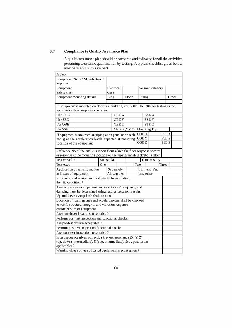
6.7 Compliance to Quality Assurance Plan
A quality assurance plan should be prepared and followed for all the activitiespertaining to seismic qualification by testing. A typical checklist given belowmay be useful in this respect.
ProjectEquipment: Name/ Manufacturer/SupplierEquipment Electrical Seismic categorySafety class classEquipment mounting details Bldg Floor Piping Other
If Equipment is mounted on floor in a building, verify that the RRS for testing is theappropriate floor response spectrumHor OBE OBE X SSE XHor SSE OBE Y SSE YVer OBE OBE Z SSE ZVer SSE Mark X,Y,Z On Mounting Drg.If equipment is mounted on piping or on panel OBE X SSE Xor on rack etc. give the acceleration levels OBE Y SSE Yexpected at mounting location/of the equipment OBE Z SSE Zobtained by analysis reports of supportingpiping/panel or rack/stand as applicable
Test Waveform Sinusoidal Time-HistoryTest Axes One Two ThreeApplication of seismic motion Separately Hor. and Ver.in 3 axes of equipment All together any otherIs mounting of equipment on shake table simulatingthe site condition ?Are resonance search parameters acceptable ? Frequency anddamping must be determined using resonance search results.Up and down sweep both shall be done.Location of strain gauges and accelerometers shall be checkedto verify structural integrity and vibration responsecharacteristics of equipmentAre transducer locations acceptable ?Perform post test inspection and functional checks.Are pre-test criteria acceptable ?Perform post test inspection/functional checksAre post-test inspection acceptable ?Is test sequence given correctly (Pre-test, resonance (X, Y, Z)(up, down), intermediate), 5 (obe, intermediate), See , post test asapplicable) ?Warning clause on use of tested equipment in plant given ?
60
If equipment is mounted on piping or on panel or on racketc. give the acceleration levels expected at mountinglocation of the equipment
Reference No of the analysis report from which the floor response spectraor response at the mounting location on the piping/panel/ rack/etc. is taken
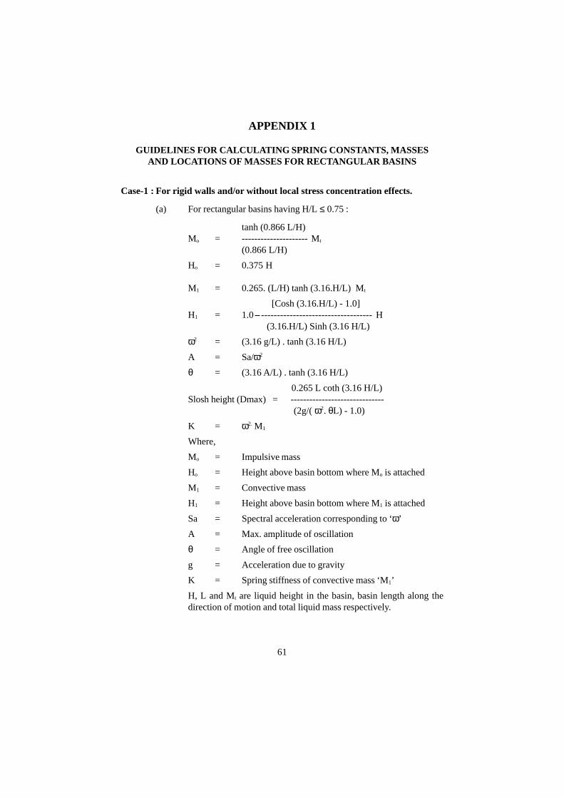
APPENDIX 1
GUIDELINES FOR CALCULATING SPRING CONSTANTS, MASSESAND LOCATIONS OF MASSES FOR RECTANGULAR BASINS
Case-1 : For rigid walls and/or without local stress concentration effects.
(a) For rectangular basins having H/L ≤ 0.75 :
tanh (0.866 L/H)Mo = --------------------- Mt
(0.866 L/H)
Ho = 0.375 H
M1 = 0.265. (L/H) tanh (3.16.H/L) Mt
[Cosh (3.16.H/L) - 1.0]H1 = 1.0 ----------------------------------- H
(3.16.H/L) Sinh (3.16 H/L)
ω2 = (3.16 g/L) . tanh (3.16 H/L)
A = Sa/ω2
θ = (3.16 A/L) . tanh (3.16 H/L)
0.265 L coth (3.16 H/L)Slosh height (Dmax) = ------------------------------
(2g/( ω2. θL) - 1.0)
K = ω2. M1
Where,
Mo = Impulsive mass
Ho = Height above basin bottom where Mo is attached
M1 = Convective mass
H1 = Height above basin bottom where M1 is attached
Sa = Spectral acceleration corresponding to ‘ω’
A = Max. amplitude of oscillation
θ = Angle of free oscillation
g = Acceleration due to gravity
K = Spring stiffness of convective mass ‘M1’
H, L and Mt are liquid height in the basin, basin length along thedirection of motion and total liquid mass respectively.
61
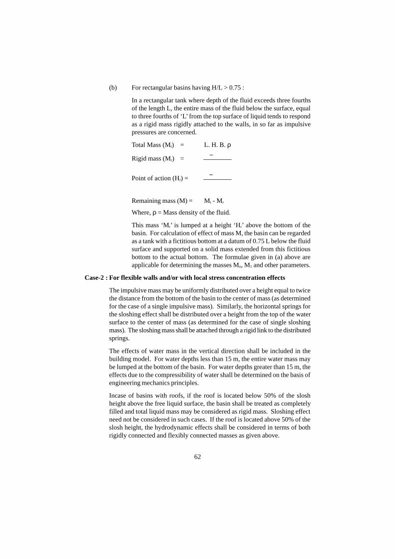
(b) For rectangular basins having H/L > 0.75 :
In a rectangular tank where depth of the fluid exceeds three fourthsof the length L, the entire mass of the fluid below the surface, equalto three fourths of ‘L’ from the top surface of liquid tends to respondas a rigid mass rigidly attached to the walls, in so far as impulsivepressures are concerned.
Total Mass (Mt) = L. H. B. ρ
Rigid mass (Mr) =
Point of action (Hr) =
Remaining mass (M) = Mt - Mr
Where, ρ = Mass density of the fluid.
This mass ‘Mr’ is lumped at a height ‘Hr’ above the bottom of thebasin. For calculation of effect of mass M, the basin can be regardedas a tank with a fictitious bottom at a datum of 0.75 L below the fluidsurface and supported on a solid mass extended from this fictitiousbottom to the actual bottom. The formulae given in (a) above areapplicable for determining the masses Mo, M1 and other parameters.
Case-2 : For flexible walls and/or with local stress concentration effects
The impulsive mass may be uniformly distributed over a height equal to twicethe distance from the bottom of the basin to the center of mass (as determinedfor the case of a single impulsive mass). Similarly, the horizontal springs forthe sloshing effect shall be distributed over a height from the top of the watersurface to the center of mass (as determined for the case of single sloshingmass). The sloshing mass shall be attached through a rigid link to the distributedsprings.
The effects of water mass in the vertical direction shall be included in thebuilding model. For water depths less than 15 m, the entire water mass maybe lumped at the bottom of the basin. For water depths greater than 15 m, theeffects due to the compressibility of water shall be determined on the basis ofengineering mechanics principles.
Incase of basins with roofs, if the roof is located below 50% of the sloshheight above the free liquid surface, the basin shall be treated as completelyfilled and total liquid mass may be considered as rigid mass. Sloshing effectneed not be considered in such cases. If the roof is located above 50% of theslosh height, the hydrodynamic effects shall be considered in terms of bothrigidly connected and flexibly connected masses as given above.
tMH
L75.0H −
2
L75.0H −
62
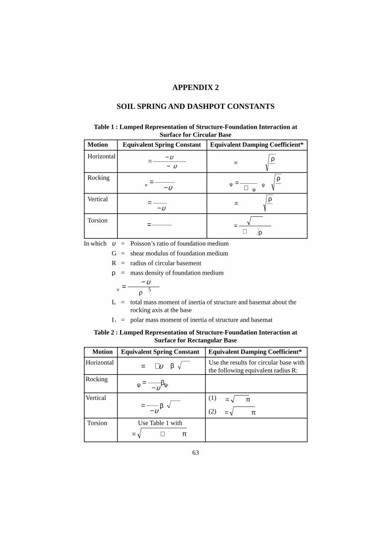
BLG ÿ)1(2k xx υ+=
Motion Equivalent Spring Constant Equivalent Damping Coefficient*
Horizontal
Rocking
Vertical
Torsion
APPENDIX 2
SOIL SPRING AND DASHPOT CONSTANTS
Table 1 : Lumped Representation of Structure-Foundation Interaction atSurface for Circular Base
υυ87
GR)1(32k r −
−=
υ−=
1
GR4k z
3
GR16k
3
t =
In which υ = Poisson’s ratio of foundation medium
G = shear modulus of foundation medium
R = radius of circular basement
ρ = mass density of foundation medium
Io = total mass moment of inertia of structure and basemat about therocking axis at the base
I t = polar mass moment of inertia of structure and basemat
Table 2 : Lumped Representation of Structure-Foundation Interaction atSurface for Rectangular Base
Motion Equivalent Spring Constant Equivalent Damping Coefficient*
Horizontal Use the results for circular base withthe following equivalent radius R:
Rocking
Vertical (1)
(2)
Torsion Use Table 1 with
63
G
ÿRk576.0c rr =
ρ
G
ÿRk0.85c zz =
ρ
G
ÿRk
B1
30.0c �
�� +
=ρ
ψψ
ψ
5t
ttt
ÿRI21
Ikc
+=
ρ
2ÿÿ BL�
1
Gk
υ−= βψψ
ationfor translBL/ ÿR = π
rockingforÿ3/BLR 4 3= π
4 22 ÿ6/)LBL(BR += π
)1(3
GR8k
3
ÿ υ−=
5
oÿ R8 �
)I(1B
3 υ−= 5
BLÿ1
Gk zz υ−
= β
β
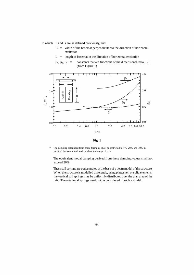
In which υ and G are as defined previously, and
B = width of the basemat perpendicular to the direction of horizontalexcitation
L = length of basemat in the direction of horizontal excitation
βx, βψ, βz = constants that are functions of the dimensional ratio, L/B(from Figure 1)
Fig. 1
* The damping calculated from these formulae shall be restricted to 7%, 20% and 30% inrocking, horizontal and vertical directions respectively.
The equivalent modal damping derived from these damping values shall notexceed 20%.
These soil springs are concentrated at the base of a beam model of the structure.When the structure is modelled differently, using plate/shell or solid elements,the vertical soil springs may be uniformly distributed over the plan area of theraft. The rotational springs need not be considered in such a model.
64
βx
βψ
βz
β x or
β z
β ψ
L / B
2.0
3.0
1.0
0.00.1 0.2 0.4 0.6 1.0 2.0 4.0 6.0 8.0 10.0
0.0
0.5
1.0
1.5
B
Axi
s of
Roc
king

ANNEXURE 1
SPECIAL STRUCTURES
A1.1 Buried Pipes
Long, buried structures are primarily subjected to strains induced by grounddeformation due to seismic wave passage and by differential displacementbetween an anchor point to a building and the surrounding ground. Inertialeffects are unimportant for design of such structures. Important considerationsfor design of such structures are given below. For more details on responsecalculations, ASCE 4-98 may be referred.
A1.1.1 Straight sections away from anchor points, sharp bends or intersections.
Such sections are designed to withstand maximum axial strain and maximumbending strain induced due to seismic wave passage, assuming each point onthe structure moves with the ground. Upper bound of the axialstrain may becalculated considering slippage between the structure and the ground basedon the maximum friction force at the interface.
Flexible joints in straight segments should withstand the maximum relativejoint displacement and joint rotation calculated on the basis of maximumground motion parameters and spacing between the joints. Generally, suchdisplacement/rotation are negligible and are often ignored.
A1.1.2 Forces on bends, intersections and anchor points.
Axial force is calculated on the basis of the maximum strain calculated as perA1.1.2. Bending moments and shears are calculated by considering the buriedstructure as a beam on an elastic foundation subjected to the axial force statedabove.
A1.1.3 Anchor point movement.
Forces and strains due to the maximum relative dynamic movement betweenanchor points and the adjacent soil shall be calculated. The motion of adjacentanchor points shall be considered to be out of phase in such calculations.
Forces and strains associated with the relative movement of anchor pointsshall be combined with thecorresponding forces and strains from wavepropagation effects using the SRSS method.
A1.2 Earth Retaining Walls
A1.2.1 General Requirements
(a) Earth-retaining walls including basements of building structures shallbe analysed for seismic-induced soil pressures.
65
(b) For cantilever retaining walls, the active solution may be used.
(c) For basements of building structures elastic solution should be usedfor earth pressure calculations.
(d) The summation of dynamic seismic soil pressures and static earthpressure shall not exceed soil static passive earth pressure.
A1.2.2 Elastic Solution
A conservative estimate of dynamic soil pressures and the correspondingresultant force and overturning moment may be obtained from ASCE 4-98.For design purpose, static soil pressure shall be calculated separately andcombined with the dynamic soil pressure calculated above with appropriateload factors.
A1.2.3 Active Solution
Total of the static and dynamic soil pressures (PAE) may be established as perthe Mononobe - Okabe method using ASCE 4-98. In order to allow for theuse of different load factors for the static and dynamic earth pressures, theoverall soil pressure during a seismic event is separated into the staticcomponent (PA) and the dynamic increment (∆PAE). The dynamic soil pressure(∆PAE) is applied at two-third of the soil embedment height from the bottom.The variation of dynamic soil pressures along the height of the wall may berepresented by an inverted triangle with the maximum pressure at the groundsurface.
A1.3 Vertical Tanks with Free Liquid Surface
When a vertical tank containing liquid is accelerated in a horizontal direction,a certain portion of the liquid acts as if it were a solid mass in contact with thewalls. The force exerted by this mass is called the impulsive force. Theacceleration also induces oscillations of the liquid, contributing to additionaldynamic pressure on the wall and the bottom. This can be thought as a certainportion of the liquid responding as if it were a solid mass connected to thewalls through flexible springs. The associated force is called the convectiveforce. Important considerations for including both impulsive and convective(sloshing) effects in the design of such tanks are given below. For more detailson response calculations, ASCE-4-98 may be referred.
The horizontal response analysis shall include at least one impulsive mode.The effective fluid weight (only a portion of the total weight), the height atwhich it is attached to the tank can be computed using formulas inASCE-4-98. The fundamental horizontal frequency of vibration of the tankshell including the impulsive contained fluid weight can be determined usingthe methods which account for the flexibility of the tank shell and the effectiveimpulsive fluid mass. The horizontal impulsive mode spectral acceleration
66
shall be determined using this impulsive mode frequency and tank shelldamping. In lieu of determining the impulsive mode fundamental frequency,it is permissible to use the peak horizontal spectral acceleration for the tankshell damping value. The spectral acceleration is used in calculating theoverturning moment and hydrodynamic pressures acting on the tank shell.The overturning moment at the base of the tank due to the fundamentalimpulsive mode shall include the effects of the impulsive mode effective fluidweight and the effects of the weight of the tank shell acting in phase.
Similarly, in the fundamental horizontal convective mode for a verticalcylindrical tank, the effective fluid weight and height from the bottom of thecylindrical shell to the centroid of the sloshing weight as well as the fundamentalsloshing mode frequency can be obtained using formulas in ASCE-4-98. Thehorizontal sloshing mode spectral acceleration shall be determined using theabove sloshing mode fundamental frequency and damping ratio equal to 0.5%of critical damping. The spectral acceleration is used in calculating theoverturning moment and hydrodynamic pressures acting on the tank shell.For the sloshing mode, the additional quantity of importance is the slosh height.If the tank top is not located above the slosh height, it shall be analyzed for thecontact pressures and impact force that result from fluid sloshing against it.
If the distance form the top head to the water surface is less than 50% of theslosh height above the top of the fluid, the tank shall be treated as being full.For a full tank, 100% of the fluid weight shall be incorporated into the horizontalimpulsive mode. In this case, a horizontal sloshing mode need not beconsidered.
The contribution of the vertical motion to hydrodynamic pressure shall alsobe considered. The spectral acceleration needed for this purpose, shall becalculated at the vertical fluid response mode natural frequency and dampingequal to shell material damping.
The maximum overturning moment at the base of the tank shall include theeffects of the impulsive and sloshing horizontal moments. An acceptablemethod of combining these effects is the SRSS method.
The tank shall also be evaluated for buckling considering seismically inducedlongitudinal compressive loads. French Code RCC-MR (2002) (Design andConstruction Rules for FBR Nuclear Islands, section-I, sub-section-Z (OtherTechnical Appendices), AFCEN, Paris, 2002) may be referred for more details.
The seismic-induced hydrodynamic pressure on the tank shell at any levelmay be determined by the SRSS combination of the horizontal impulsive,horizontal sloshing, and vertical hydrodynamic pressures. The hydrodynamicpressure at any level shall be added to the hydrostatic pressure at that level todetermine the hoop tension in the tank shell. ASME/BPVC-2003, Section-III, Div. 1, Appendix-N titled ‘Dynamik Analysis Methods’ may be referredfor damping values and modal damping calculations for coupled fluid-structureanalysis.
67
ANNEXURE 2
GENERAL DESIGN GUIDELINES FOR STRUCTURES,EQUIPMENT AND PIPING
A2.1 General Design Guidelines for Structures
A2.1.1 Layout Selection
Seismic effects should be minimised by:
(i) Locating the centre of gravity of all structures as low as possible;
(ii) Selecting a plan and elevation that is as simple and regular as possible;
(iii) Avoiding protruding sections (lack of symmetry) as far as possible;
(iv) Making the centre of rigidity at the various elevations as close to thecentre of gravity as practicable.
(v) To reduce undesirable differential movements between structures,consideration should be given to locate the structures, to the extentpracticable, on a common foundation structure, or at least, avoidingdifferent embedment depths.
A2.1.2 Design Guidelines
(i) Brittle failure in shear and/or bond, or in the compressive zones ofconcrete should be prevented in RC structures;
(ii) An appropriate minimum compressive strength of concrete shouldbe fixed to ensure the ultimate strength of the structural members isgoverned by the reinforcement;
(iii) For rebars, an appropriate minimum ratio between UTS and YS(~1.25) should be defined, to guarantee a minimum ductility (~10%);
(iv) Appropriate design of structural joints, particularly in RC structuresshould provide a high ductility and a capability to accommodate highdisplacements and rotations. Guidelines of IS 13920-1993 (Code ofPractice - Ductile Detailing of Reinforced Concrete StructuresSubjected to Seismic Forces) may be followed in this regard.
A2.2 General Design Guidelines for Equipment and Piping
Following points should be taken into account to improve the resistance ofequipment to an earthquake-induced vibration:
(a) For the portions of the equipment with a certain degree of freedom in
68

design, the position of the center of gravity should be made as low aspossible, and the mounting should be as stable as possible.
(b) In case when equipment with a lower safety class is closely locatedto equipment with a higher safety class, it is necessary to check theconfiguration plan to make sure that the damage to the equipmentwith a lower safety class due to earthquake does not affect theequipment with a higher safety class.
(c) As far as the pressure vessel itself is concerned, usually the platethickness is controlled by the pressure (and not by seismic load) andthe effect of the seismic force on the equipment is relatively small incomparison with the normal stress during operation. However, forthe support structure, since the seismic force is dominant, appropriatestrength check should be made considering the seismic force. It isalso necessary to ensure enough stiffness for the support, particularly,in the design of the anchorage, where there is a likelihood of damage.It is of particular importance to ensure that base plates are sufficientlystiff to avoid prying effects and that anchor bolts are adequatelytightened to avoid rocking effects, lowered frequencies, increasedresponse levels, higher-than-design loads and increased risk ofloosening, pull-out or fatigue. Over-designed or redundant bolts,pre-loaded on installation to the tensile force expected during a seismicevent are therefore recommended.
(d) In addition, the seismic supports should be such that they do not causedifficulties in the maintenance and servicing of the machines/equipment.
(e) It is important to avoid, as far as practicable, resonance of equipment,piping, instrumentation and core internals at the frequency of thedominant modes of supporting structures. In most cases, stiffnesscan be increased to avoid resonance. In some cases, when systemsare made stiffer, the effect of thermal stresses, other dynamic loadsand differential motions of supporting points may become significant.
(f) For S2 Level earthquake ground motion, equipment may enter therange of nonlinear/elasto-plastic behavior. In this case, it is necessaryto make sure that the required ductility is present in the system,particularly in the embedded parts (EPs). The design of the embeddedpart (EP) of the support should be such that the failure in concrete isavoided. Therefore, the strength of the load path through concreteshould be much more than the strength of the anchorage rod of theEP.
(g) Particular attention should be paid to the possibility of collisionbetween adjacent components, or between components and adjacentparts of a building, as a consequence of their dynamic displacement.
69
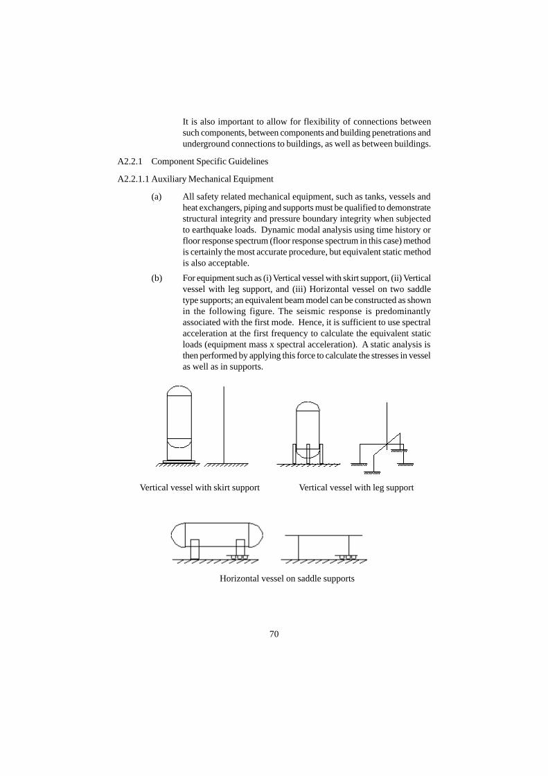
It is also important to allow for flexibility of connections betweensuch components, between components and building penetrations andunderground connections to buildings, as well as between buildings.
A2.2.1 Component Specific Guidelines
A2.2.1.1 Auxiliary Mechanical Equipment
(a) All safety related mechanical equipment, such as tanks, vessels andheat exchangers, piping and supports must be qualified to demonstratestructural integrity and pressure boundary integrity when subjectedto earthquake loads. Dynamic modal analysis using time history orfloor response spectrum (floor response spectrum in this case) methodis certainly the most accurate procedure, but equivalent static methodis also acceptable.
(b) For equipment such as (i) Vertical vessel with skirt support, (ii) Verticalvessel with leg support, and (iii) Horizontal vessel on two saddletype supports; an equivalent beam model can be constructed as shownin the following figure. The seismic response is predominantlyassociated with the first mode. Hence, it is sufficient to use spectralacceleration at the first frequency to calculate the equivalent staticloads (equipment mass x spectral acceleration). A static analysis isthen performed by applying this force to calculate the stresses in vesselas well as in supports.
Vertical vessel with skirt support Vertical vessel with leg support
Horizontal vessel on saddle supports
70

(c) The equivalent static force together with the overturning moment actson the anchorage system and should be designed to withstand them.
(d) For horizontal Pumps, fans and motor generators, the driver and thedriven component should be connected by a rigid base or commonskid to avoid differential displacement between the driver and thedriven component, which could cause shaft misalignment.
(e) Avoid long unsupported pipe or a heavy valve attached to the pipenear the equipment, which may cause excessive nozzle loads resultingin damage to the pump nozzle or pump casing distortion causingbending.
(f) For vertical pumps, the impeller shaft and casing should not becantilevered for more than 6 m below the pump mounting flange. Itshould have a radial bearing at the bottom of the casing to supportthe impeller shaft. Otherwise, there is a possibility of misalignmentand bearing damage due to excessive lateral loads, damage to theimpeller due to excessive displacement and damage due to interfloordisplacement on multi-floor supported pumps.
A2.2.1.2 Vertical Tanks Containing Liquids
Liquid containing vertical tanks, in which the upper liquid surface is essentiallyunconstrained (free), are subjected to additional loading due to the motion ofthe liquid. Part of the liquid moves in an impulsive mode, in which the liquidmoves in unison with the tank shell; while the remaining portion of the liquidmoves in a convective (sloshing) mode, independent of the tank shell.
Guidelines given in Annexure 1 along with ASCE 4-98 can be followed forthe seismic qualification of these tanks.
A2.2.1.3 Active Components
The guidelines provided for design of structures, systems and component (SSC)by analytical method provide assurance of structural integrity and pressureboundary integrity.
For active components, viz., valves, pumps, fans, blowers, motors,compressors, diesel generators; electrical; and instrumentation panels devicesviz. relays, pushbuttons, switches, circuit breakers etc. apart from structuraland pressure boundary integrity, an assurance is also required about thefunctionality of the equipment during and/or after earthquake.
The performance of some ‘active’ equipment (e.g. pumps, valves and dieselgenerator sets) under earthquake conditions can be calculated with adequateconfidence by analysis, when their potential failure modes can be identifiedand described in terms of stress, deformation (including clearances) or loads.Typically this would involve calculating the relative displacement between
71
the members likely to rub against each other and showing existence of adequateclearance to justify its functionability. The integrity of shaft bearings shouldalso be assessed for the seismic loads. This specific requirement should be apart of the component specifications. It should be understood that a highlevel of analytical sophistication requires a number of assumptions andproduces at best only an indicator of seismic behavior. Therefore, it isrecommended that test or experiment be conducted to validate such analyticalresults, particularly with regard to functionality of the equipment.
For components such as electrical and instrumentation panels, devices viz.relays, pushbuttons, switches, circuit breakers etc. seismic qualification bytesting is the recommended method.
For the shutdown system, it should be demonstrated by testing that the shutoffrods can be inserted into the core within a period required to meet the intendedfunction.
When functionality of typical equipment has been demonstrated by analyticalor experimental means for an earthquake motion, similar equipment can beconsidered qualified.
A2.2.1.4 Cranes
(a) For the main body (girder) of the crane, evaluation is performed for abeam model having its both ends simply supported. Since the vibrationcharacteristics and stress generated depend on the trolley's position,it is necessary that the analysis be performed for different trolleyspositions. For the strength calculation in the running direction at thesupport position, seismic acceleration equal to the gravitation constantmultiplied by friction coefficients between the rail and wheel shouldbe taken. For the transverse direction (direction perpendicular to therunning rails), since the girder is taken as a rigid body, the seismicresponse acceleration is equal to the seismic motion of the buildingat the mounting position. Apart from structural integrity check, it isnecessary to provide a mechanism to prevent the jumping of the cranefrom rails.
(b) Make design provisions for tethering or clamping cranes/hoists in asafe position when out of service.
(c) Lower loads onto safe areas when hoisting/handling operations areover (administrative).
A2.2.1.5 HEPA Filters
HEPA filters are generally lightweight and firmly held in position to a frameby some type of restraining mechanism. The frame should be evaluated foroverall stability. No permanent deformation should take place that can affect
72

the function of the filter bank. The restraining mechanism should restrain thefilters from coming loose during an earthquake. HEPA filter needs to befunctionally qualified.
A2.2.1.6 Ventilation Ducts
Seismic design of a ventilation duct consists of structural integrity check andis usually performed using one of the following methods :
(a) Dynamic analysis is performed using the modal response spectrummethod to calculate the seismic load and to evaluate the strength.
(b) Alternatively, equivalent static seismic force is calculated dependingon the natural frequency of the first mode of vibration andcorresponding spectral acceleration. The natural frequency iscalculated using the theoretical formula derived under the assumptionthat the duct is a beam with its two ends simply supported.
In either case, the span of the support should be shorter than the allowablelimit from buckling considerations. The allowable span is calculated usingthe theoretical formula derived under the assumption that the duct is a beamwith its two ends simply supported.
A2.2.1.7 Cable Trays
Cable trays and the supports should continue to maintain overhead supportfor the cables during and after the seismic event. Cable tray supports aremounted on a cantilever beam from an adjacent structural wall or are suspendedfrom ceiling. The mounting configuration should be rigid for lateral response(braced against the wall), so dynamic amplification of seismic motion isminimal. Where rigidity cannot be achieved without an excessive increase insupport member sizes, it becomes necessary to design the supports on thebasis of amplified seismic loads obtained from the floor response spectra.
Following are some of the good design practices to aid the design process :
(i) The length of the unsupported cable tray between adjacent supportsshould not exceed 3 m in the direction of the run. Beyond the lastsupport, the cable tray should not cantilever out by more than 1.5 m.
(ii) There should be sufficient distance between adjacent systems so thatthere is no seismic interaction with other systems.
(iii) Cable trays should be secured to their supports so the trays or conduitcannot slide and fall off the supports.
(iv) Cables above the top of the sides of the tray should be restrained tokeep them in the tray to prevent them from flopping or falling out ofthe trays and being pinched or cut.
73

(v) All cable tray supports should pass a vertical capacity check of 4times the dead load.
(vi) Consideration should be given to the seismic adequacy of the wall towhich the cable tray and conduit raceway supports are attached.Reinforced concrete walls are not a concern.
A2.2.1.8 Electrical Systems, Control and Instrumentation Devices, Panels and Racks
The active components of electrical and control and instrumentation systemsget qualified by testing. If the panel/rack is not part of the test, it is essentialthat the panel/rack be checked for structural integrity by analysis. If the deviceis qualified for a 3.5 g flat spectrum, it is necessary to show that the accelerationat device location is less than 3.5 g.
It has been observed that a significant cause of these systems failing to functionproperly during and after an earthquake, is lack of anchorage or inadequateanchorage. Analyses should be performed to compare the anchorage capacityto the demand imposed by the seismic loading. This capacity evaluation shouldextend down to the embedded parts and the concrete structure.
A2.2.1.9 Good Practices
It has been observed that failures have occurred because seemingly minorthings were ignored during detailing. Following guidelines are provided topreclude such occurrences :
(a) Oversized washers or reinforcing plates are recommended for thinequipment bases. Lock washers are recommended where even low-level vibration exists.
(b) There should be no gap at the bolt or stud anchor locations forequipment containing essential relays, since they have the potentialfor opening and closing due to the load reversals during earthquake.This may cause impact loading on the equipment leading to generationof high frequency vibrations and may result in chatter of essentialrelays mounted therein.
(c) Lack of adequate stiffness in the anchorage raises two concerns. First,the natural frequency could be lowered into the resonance range.Second, it could cause lift up of the cabinet off the floor during anearthquake resulting in high frequency impact loading and chatter ofrelays. Such inadequate stiffness may arise due to use of thin framemembers and clip angles in the construction of motor control centers,switchgear, and instrumentation and control cabinets. Stiff load pathswith little eccentricity are preferable for anchorages.
(d) Battery racks should have close-fitting, crush-resistant spacersbetween the cells, which fill about two-thirds of the vertical space
74

between the cells, to avoid rocking and colliding during the earthquakecausing malfunction and damage. The battery racks should also haveend and side rails, which are close fitting against the cells (with shims,if needed) to avoid tipping the batteries or sliding off the rack.
(e) Adjacent cabinets of motor control centers, switchgear, distributionpanels, transformers which are close enough to impact each othershould be bolted together to avoid unbolted cabinets responding outof phase to one another and impacting each other during an earthquake.The resulting high frequency vibration loadings could cause essentialrelays to chatter.
(f) Cabinets for the above mentioned items should not have large size(> 150 mm wide and 300 mm high) cutouts in the lower half of thecabinet. The concern is that the shear load from the earthquake willnot be able to be transferred through the shear walls to the anchorage.Alternatively, the cutouts should be adequately reinforced.
(g) All doors and drawout panels should be secured by a latch or a fastener.The concern addressed is that the doors or drawout panels could openduring an earthquake and repeatedly impact the housing, causinginternal components such as relays and contactors to malfunction orchatter.
(h) For floor-mounted units such as battery chargers and inverters, thetransformer, which is the heaviest component of this equipment, shouldbe positively anchored and mounted near the base of the cabinet.
(i) For temperature sensors, the detrimental differential displacementbetween the mounting of the connection head and the mounting ofthe temperature sensor should not occur so as to prevent the wiring tobe pulled out of the sensor.
(j) Valves with heavy operators should not be mounted on small lines(< 1” dia) or, valve, operator and the line should be well supportedand anchored to the same support structure to avoid overstressing ofadjacent piping.
(k) Valve operator cantilever length (distance between centerline of pipeto the top of the operator) should not be too large.
(l) The valve actuator and the yoke should not be independently bracedto the structure unless the pipe is also braced to the same structureimmediately adjacent to the valve. If the operator is independentlysupported from the valve and attached piping, it may act as a pipesupport and attract considerable load through yoke and possibly failor bind the shaft. If both the operator and the valve/pipe are restrained,and if they are both not tied to the same support structure, thendifferential motion may lead to high seismic loads.
75
A2.3 General Design Considerations for Piping
(a) To provide seismic restraints for piping and components and at thesame time allow for thermal deformations, dampers or motion limitingstops should be used. Excessive use of snubbers should be avoideddue to their implications on operation and maintenance.
(b) Realistic damping values should be used to define seismic designinput, since over design for seismic loads can reduce design marginsfor thermal loads.
(c) When a concentrated mass, such as a valve, is attached to the piping,there is a possibility of large torsional moment getting generated dueto eccentric mass. This can be avoided by placing a support as nearthe discrete mass as possible.
A2.3.1 Span between Vertical Supports
Piping shall be well supported vertically. A piping system may be consideredwell supported for deadweight if the equivalent span length between verticalsupports, for liquid or gas service, is as given in ASME B31.1 Table 121.5,Suggested pipe support spacing). These values are based on a bending stressof 160 kg/sq.cm and maximum sag of 2.5 mm
A2.3.2 Span between Lateral Supports
Piping shall be sufficiently restrained in the lateral direction. In general, apiping system may be considered sufficiently restrained in the lateral directionif the equivalent lateral span length for liquid or gas service does not exceedthree times the spans for vertical supports. Lateral restraint may be providedeither by an engineered lateral support or by other means such as :
(a) U-Bolts - provides significant lateral restraint but no longitudinalrestraint along pipe axis.
(b) Saddles - simple saddle without yoke or strap does not providehorizontal restraint. A deep saddle will provide restraint even withoutstraps.
(c) Floor and Wall penetrations - provide restraint when gaps close.
A2.3.3 Anchor Motion
Piping must have sufficient flexibility to accommodate the seismic motions ofstructures, equipment and headers to which it is attached.
One of the most common causes of piping failure in strong motion earthquakesis Seismic Anchor Movement (SAM) resulting from:
(a) large displacement of unanchored tanks or equipment
76
(b) large displacement due to flexibility of the tank or equipmentanchorage
(c) large differential motions of structures to which the piping is attached
(d) large motions of header piping induced into smaller branch piping
Suggested remedies are :
(i) Tanks and equipment to which piping attaches, must be properlyanchored to prevent sliding, rocking or overturning.
(ii) Tanks and equipment to which piping attaches, and the supports shouldbe relatively stiff to minimize SAM. When vibration isolators arepresent, they are a source of SAM. If there are no seismic stops builtinto the isolators, the equipment will require the addition of seismicrestraints to limit motion.
(iii) Piping rigidly attached to two different buildings or substructureswithin a building must be sufficiently flexible to accommodate thedifferential motion. Pay attention to piping that has its axial motionrestrained at supports points in two different structures.
(iv) Header motion imposed on small branches must be assessed, or theheader must be restrained near the branch.
A2.3.4 Equipment Nozzle Loads
Equipment and component nozzles, except for valves that are stronger thanthe pipe, should be protected, by appropriate restraints, from excessive seismicloads. Piping layout should be reviewed to evaluate that large seismic loadsare not reacted at the equipment nozzle. One potential problem is a long axialrun of pipe not restrained from axial movement except at the equipment nozzle.
Piping reaction loads at the nozzles of rotating equipment may affect theirfunction. The seismic reaction loads imparted by the piping on the nozzle ofthe active (rotating) equipment shall be within the estimated capability of theequipment.
A2.3.5 Interaction with other Structures
A piping system subjected to seismic loads will displace or swing laterally,and may impact adjacent components. Lateral displacements or swingdeflections of piping spans shall be estimated. An approximate formula is :
Sd =
Sd = lateral displacement
f = natural frequency Hz
77
1.3 Sa
(2πƒ)2

Sa = spectral acceleration at f
Impact must be avoided if it affects the following components :
• Active components
• Instrumentation tubing
• Unstable or light weight structures
• Electrical cabinets and panels
78

79
REFERENCES
1. ATOMIC ENERGY REGULATORY BOARD, Safety Classification andSeismic Categorisation of Structures, Systems and Components of PressurisedHeavy Water Reactors; AERB Safety Guide No. AERB/SG/D-1, Mumbai,India, 2002.
2. ATOMIC ENERGY REGULATORY BOARD, Code of Practice on Designfor Safety in Pressurised Heavy Water Based Nuclear Power Plants; AERBCode No. AERB/SC/D, Mumbai, India, 1989.
3. ATOMIC ENERGY REGULATORY BOARD, Seismic Studies and DesignBasis Ground Motion for Nuclear Power Plants; AERB Safety Guide No.AERB/SG/S-11, Mumbai, India, 1990.
4. ATOMIC ENERGY REGULATORY BOARD, Civil Engineering StructuresImportant to Safety of Nuclear Facilities; AERB Safety Standard No. AERB/SS/CSE, Mumbai, India, 1998.
5. AMERICAN SOCIETY OF CIVIL ENGINEERS, Seismic Analysis of Safety-Related Nuclear Structures and Commentary; ASCE 4-98, Virginia, USA, 2000.
6. S.J. Hyde et al., ‘Seismic Analysis of Auxiliary Mechanical Equipment inNuclear Plants’.
7. Mihailo D. Trifunac et al., 'Full Scale Experimental Studies of Soil StructureInteraction - A Review'; Proc. 2nd US-Japan Workshop on Soil-StructureInteraction, March 2001, Tsukuba, Japan.
8. INTERNATIONAL ATOMIC ENERGY AGENCY, Seismic Design andComponent Qualification for Nuclear Power Plants; IAEA Safety Guide NS-G-1.6, Vienna, Austria, 2003.
9. US DEPARTMENT OF ENERGY, Seismic Evaluation Procedure forEquipment in US DOE Facilities; DOE/EH-0545, March 1997.
10. JAPAN ELECTRIC ASSOCIATION, Aseismic Design Technical Guidelinesfor Nuclear Power Plants; JAEG-4601, 1987.
11. THE INSTITUTION OF ELECTRICAL AND ELECTRONICSENGINEERS, IEEE Recommended Practice for Seismic Qualification of Class1E equipment for Nuclear Plants, IEEE Std 344-1987.
12. John Nedderman, ‘Designing Plants to Withstand Earthquakes’; NuclearEngineering International, August 1995.
13. BUREAU OF INDIAN STANDARDS, Criteria for Earthquake ResistantDesign of Structures; IS 1893, New Delhi, India. 2002.
14. USNRC Regulatory Guide 1.61, ‘Damping Values for Seismic Design ofNuclear Power Plants’, Revision 1, March 2007.

80
LIST OF PARTICIPANTS
WORKING GROUP
Dates of meeting: May 05, 2003 March 01, 2004June 02, 2003 April 05, 2004July 07, 2003 May 03, 2004August 04, 2003 June 07, 2004September 01, 2003 July 05, 2004October 06, 2003 August 02, 2004November 03, 2003 September 06, 2004December 01, 2003 October 04, 2004January 05, 2004 November 01, 2004February 02, 2004 December 06, 2004
Members of Working Group:
Shri K.K. Vaze (Chairman) : BARC
Shri A.G. Chhatre : NPCIL
Dr. P. Banerji : IIT, Bombay
Shri G.K. Sharma : NPCIL
Shri L.R. Bishnoi (Member-Secretary) : AERB
Shri G.R. Reddy (Co-opted) : BARC
Shri S.A. Khan (Invitee) : AERB

81
ADVISORY COMMITTEE ON CODES, GUIDES ANDASSOCIATED MANUALS FOR SAFETY IN DESIGN OF
NUCLEAR POWER PLANTS (ACCGD)
Dates of meeting: March 14, 2004 May 15, 2005January 09, 2005 April 13, 2007
Members of ACCGD:
Shri V.K. Mehra (Chairman) : BARC
Shri S.C. Chetal : IGCAR
Shri S.A. Bahrdwaj : NPCIL
Dr. S. K. Gupta : AERB
Shri S.G. Ghadge : NPCIL
Shri K.K. Vaze : BARC
Shri B.B. Biswas : BARC
Shri S.A. Khan : AERB
Shri S.K. Dubey (Secretary) : AERB

ADVISORY COMMITTEE ON NUCLEAR SAFETY (ACNS)
Dates of meeting: January 25, 2008
Members of ACNS:
Shri G.R. Srinivasan (Chairman) : AERB (Former)
Shri S.C. Hiremath : HWB (Former)
Shri S.S. Bajaj : NPCIL (Former)
Shri R.K. Sinha : BARC
Shri H.S. Kushwaha : BARC
Prof. J.B. Doshi : IIT, Bombay
Shri D.S.C. Purushottam : BARC (Former)
Shri A.K. Anand : BARC (Former)
Shri S. Krishnamony : BARC (Former)
Dr. S.K. Gupta : AERB
Shri K. Srivasista (Member-Secretary) : AERB
82

83
PROVISIONAL LIST OF SAFETY CODES, GUIDES ANDMANUALS ON DESIGN OF PRESSURISED
HEAVY WATER REACTOR
AERB/SC/D Code of Practice on Design for Safety in Pressurised HeavyWater Based Nuclear Power Plants
AERB/NPP-PHWR/ Design for Safety in Pressurised Heavy Water Based NuclearSC/D (Rev.1) Power Plants
AERB/NPP-PHWR/ Safety Classification and Seismic Categorisation for StructuresSG/D-1 Systems and Components of Pressurised Heavy Water Reactor
AERB/SG/D-2 Structural Design of Irradiated Componenets
AERB/SG/D-3 Protection Against Internally Generated Missiles andAssociated Environmental Conditions
AERB/SG/D-4 Fire Protection in Pressurised Heavy Water Based NuclearPower Plants
AERB/SG/D-5 Design Basis Events for Pressurised Heavy Water Reactor
AERB/NPP-PHWR/ Fuel Design for Pressurised Heavy Water ReactorsSG/D-6
AERB/SG/D-7 Core Reactivity Control in Pressurised Heavy Water Reactor
AERB/NPP-PHWR/ Primary Heat Transport System for Pressurised Heavy WaterSG/D-8 Reactors
AER/SG/D-9 Process Design
AERB/NPP-PHWR/ Safety Systems for Pressurised Heavy Water ReactorsSG/D-10
AERB/SG/D-11 Emergency Electric Power Supply Systems for PressurisedHeavy Water Reactor
AERB/NPP-PHWR/ Radiation Protection Aspects in Design for PressurisedSG/D-12 Heavy Water Based Nuclear Power Plants
AERB/SG/D-13 Liquid and Solid Radwaste Management in PressurisedHeavy Water Based Nuclear Power Plants
AERB/SG/D-14 Control of Air-borne Radioactive Materials in PressurisedHeavy Water Reactors
Safety Series No. Provisional Titles

AERB/SG/D-15 Ultimate Heat Sink and Associated Systems in PressurisedHeavy Water Reactor
AERB/SG/D-18 Loss of Coolant Accident Analysis for Pressurised HeavyWater Reactor
AERB/SG/D-19 Deterministic Safety Analysis of Pressurised Heavy WaterReactor Based Nuclear Power Plants
AERB/NPP-PHWR/ Safety Related Instrumentation and Control for PressurisedSG/D-20 Heavy Water Reactor Based Nuclear Power Plants
AERB/NPP-PHWR/ Containment System Design for Pressurised Heavy WaterSG/D-21 Reactors
AERB/SG/D-22 Vapour Suppression System (Pool Type) for Pressurised HeavyWater Reactor
AERB/NPP-PHWR/ Seismic Qualification of Structures, Systems andSG/D-23 Components of Pressurised Heavy Water Reactors
AERB/SG/D-24 Design of Fuel Handling and Storage Systems for PressurisedHeavy Water Reactors
AERB/SG/D-25 Computer Based Safety Systems of Pressurised Heavy WaterReactor
AERB/NPP-PHWR/ Hydrogen Release and Mitigation Measures under AccidentSM/D-2 Conditions in Pressurised Heavy Water Reactors
AERB/NPP-PHWR/ Decay Heat Load Calculations in Pressurised Heavy WaterTD/D-1 Reactor Based Nuclear Power Plants
PROVISIONAL LIST OF SAFETY CODES, GUIDES ANDMANUALS ON DESIGN OF PRESSURISED
HEAVY WATER REACTOR (CONTD.)
Safety Series No. Provisional Titles
84

AERB SAFETY GUIDE NO. AERB/NPP-PHWR/SG/D-23
Published by : Atomic Energy Regulatory BoardNiyamak Bhavan, AnushaktinagarMumbai - 400 094INDIA. BCS