SEISMIC PERFORMANCE OF DEEP COLUMN-TO...
12
SEISMIC PERFORMANCE OF DEEP COLUMN-TO-BEAM WELDED REDUCED BEAM SECTION MOMENT CONNECTIONS J.M. Ricles, Lehigh University, U.S.A. X. Zhang, Lehigh University, U.S.A. J.W. Fisher, Lehigh University, U.S.A L.W. Lu, Lehigh University, U.S.A ABSTRACT An experimental study was conducted to investigate the seismic behavior of reduced beam section (RBS) moment connections to a deep wide flange column. The test matrix for the experimental program consisted of six full-scale interior RBS connections, where the column for the specimens ranged in depth from a W24 to a W36 wide flange section. All but one of the specimens had a composite floor slab. The results from the study show that a composite floor slab provides restraint to the top flange of the beams; reducing the magnitude of beam top and bottom flange lateral movement in the RBS, column twist, and strength degradation due to beam instability in the RBS. The performance of each of the test specimens was found to meet the seismic connection qualification criteria in Appendix S of the AISC Seismic Provisions, and thereby have sufficient ductility for seismic resistant design. The results of the experimental study, along with a nonlinear finite element study were used to develop seismic design recommendations for RBS connections to deep columns. INTRODUCTION RBS beam-to-column moment connections are often utilized in the design of special steel moment resistant frames (SMRFs). The details of a typical RBS connection are shown in Figure 1(a), where the flanges of the beam are reduced in width, away from the column face. Complete joint penetration (CJP) groove welds attach the beam flanges to the column. The beam web often is welded to the column flange with a CJP groove weld. By design, the RBS connection develops inelastic deformations primarily in the region where the beam flange width has been reduced (referred to herein as the RBS), limiting the inelastic strain developed in the beam flange-to-column CJP groove welds. With the reduction of the beam flange width, an RBS connection is more prone to inelastic local buckling of the beam web and flanges in the RBS. For economical reasons, design engineers in the U.S. prefer to use deep columns in SMRFs (as large as 914 mm in depth corresponding to a W36 wide flange section) in order to control seismic drift. Previous tests on RBS connections have been performed primarily on columns with depths corresponding to a W12 and W14 wide flange section (Roeder (1 )), where the depth was about 305 mm to 356 mm. Some tests using W27 wide flange column sections (686 mm depth) were conducted by Chi and Uang (2 ), where the connection was an exterior connection (i.e., only one beam was connected to the column). It was observed in these tests, that as a result of inelastic beam web and flange local buckling in the RBS, a lateral displacement of the beam compression flanges occurs. Shown in Figure 1(b) is the movement of the compression flanges (the top and bottom flanges of the right and left-hand beams, respectively), where F 1 and F 2 represent the beam flange compression forces of the Connections in Steel Structures V - Amsterdam - June 3-4, 2004 211
Transcript of SEISMIC PERFORMANCE OF DEEP COLUMN-TO...

SEISMIC PERFORMANCE OF DEEP COLUMN-TO-BEAM WELDED REDUCED BEAM SECTION MOMENT CONNECTIONS
J.M. Ricles, Lehigh University, U.S.A. X. Zhang, Lehigh University, U.S.A.
J.W. Fisher, Lehigh University, U.S.A L.W. Lu, Lehigh University, U.S.A
ABSTRACT An experimental study was conducted to investigate the seismic behavior of reduced beam section (RBS) moment connections to a deep wide flange column. The test matrix for the experimental program consisted of six full-scale interior RBS connections, where the column for the specimens ranged in depth from a W24 to a W36 wide flange section. All but one of the specimens had a composite floor slab. The results from the study show that a composite floor slab provides restraint to the top flange of the beams; reducing the magnitude of beam top and bottom flange lateral movement in the RBS, column twist, and strength degradation due to beam instability in the RBS. The performance of each of the test specimens was found to meet the seismic connection qualification criteria in Appendix S of the AISC Seismic Provisions, and thereby have sufficient ductility for seismic resistant design. The results of the experimental study, along with a nonlinear finite element study were used to develop seismic design recommendations for RBS connections to deep columns.
INTRODUCTION RBS beam-to-column moment connections are often utilized in the design of special steel moment resistant frames (SMRFs). The details of a typical RBS connection are shown in Figure 1(a), where the flanges of the beam are reduced in width, away from the column face. Complete joint penetration (CJP) groove welds attach the beam flanges to the column. The beam web often is welded to the column flange with a CJP groove weld. By design, the RBS connection develops inelastic deformations primarily in the region where the beam flange width has been reduced (referred to herein as the RBS), limiting the inelastic strain developed in the beam flange-to-column CJP groove welds. With the reduction of the beam flange width, an RBS connection is more prone to inelastic local buckling of the beam web and flanges in the RBS. For economical reasons, design engineers in the U.S. prefer to use deep columns in SMRFs (as large as 914 mm in depth corresponding to a W36 wide flange section) in order to control seismic drift. Previous tests on RBS connections have been performed primarily on columns with depths corresponding to a W12 and W14 wide flange section (Roeder (1)), where the depth was about 305 mm to 356 mm. Some tests using W27 wide flange column sections (686 mm depth) were conducted by Chi and Uang (2), where the connection was an exterior connection (i.e., only one beam was connected to the column). It was observed in these tests, that as a result of inelastic beam web and flange local buckling in the RBS, a lateral displacement of the beam compression flanges occurs. Shown in Figure 1(b) is the movement of the compression flanges (the top and bottom flanges of the right and left-hand beams, respectively), where F1 and F2 represent the beam flange compression forces of the
Connections in Steel Structures V - Amsterdam - June 3-4, 2004 211
two beams. Due to an eccentricity created by the lateral movement of the compression flanges, a torque is applied to the column. Deep columns tend to have thinner flanges and a web than a shallower column, resulting in a reduced torsional resistance. Consequently, there
have been concerns that the use of an RBS connection to a deep column in a SMRF can lead to inferior seismic performance because of the connection being susceptibility to torsional loading from the beams. The lack of knowledge of the performance of RBS beam-to-deep column connections under seismic loading led to a study on this topic at Lehigh University (3). The study involved both finite element analysis and experimental tests. The effects of the column depth, a composite floor slab, panel zone strength, beam web slenderness, and supplemental lateral bracing at the end of the RBS section were examined. Six full-scale specimens were subsequently tested involving different column and beam sizes, a composite floor slab and supplemental lateral bracing. Results and conclusions from the experimental study, along with some design recommendations are presented in this paper.
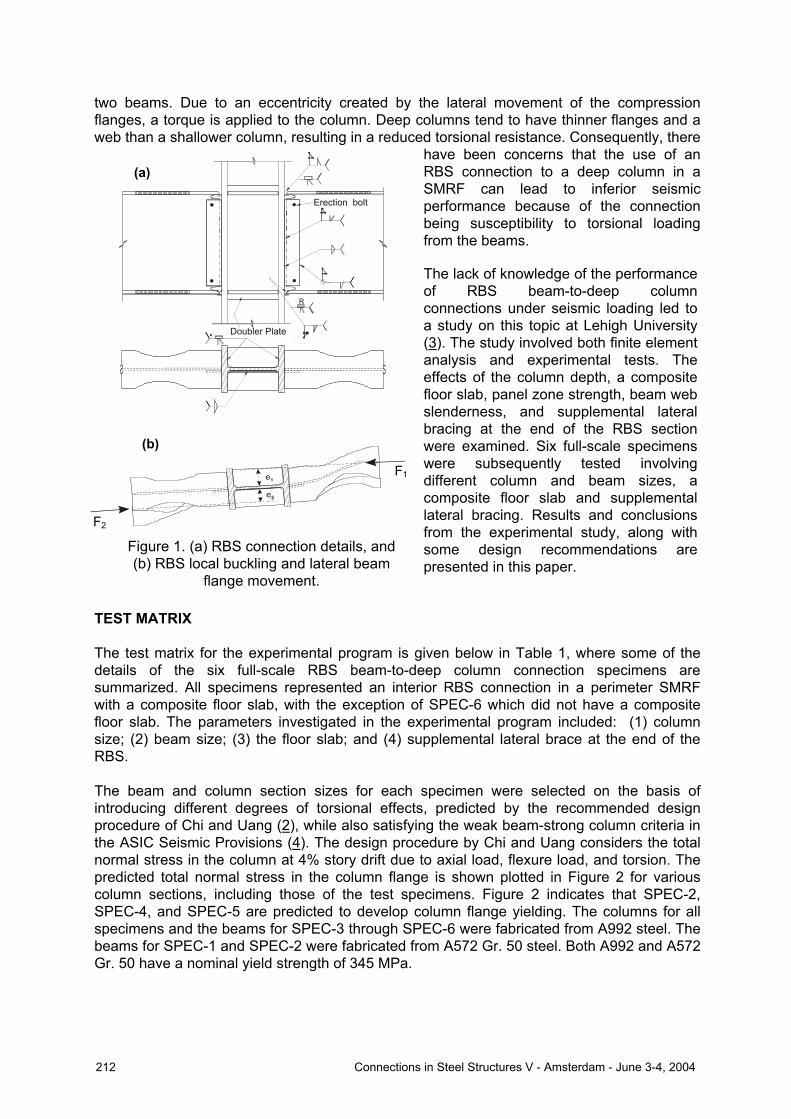
TEST MATRIX The test matrix for the experimental program is given below in Table 1, where some of the details of the six full-scale RBS beam-to-deep column connection specimens are summarized. All specimens represented an interior RBS connection in a perimeter SMRF with a composite floor slab, with the exception of SPEC-6 which did not have a composite floor slab. The parameters investigated in the experimental program included: (1) column size; (2) beam size; (3) the floor slab; and (4) supplemental lateral brace at the end of the RBS. The beam and column section sizes for each specimen were selected on the basis of introducing different degrees of torsional effects, predicted by the recommended design procedure of Chi and Uang (2), while also satisfying the weak beam-strong column criteria in the ASIC Seismic Provisions (4). The design procedure by Chi and Uang considers the total normal stress in the column at 4% story drift due to axial load, flexure load, and torsion. The predicted total normal stress in the column flange is shown plotted in Figure 2 for various column sections, including those of the test specimens. Figure 2 indicates that SPEC-2, SPEC-4, and SPEC-5 are predicted to develop column flange yielding. The columns for all specimens and the beams for SPEC-3 through SPEC-6 were fabricated from A992 steel. The beams for SPEC-1 and SPEC-2 were fabricated from A572 Gr. 50 steel. Both A992 and A572 Gr. 50 have a nominal yield strength of 345 MPa.
Figure 1. (a) RBS connection details, and (b) RBS local buckling and lateral beam
flange movement.
Doubler Plate
R
Erection bolt
F2
F1
e2
e1
(a)
(b)
F2
F1
212 Connections in Steel Structures V - Amsterdam - June 3-4, 2004
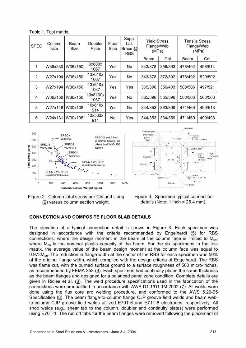
Table 1. Test matrix.
SPEC Column size
Beam Size
Doubler Plate
Floor Slab
Supp. Lat.
Brace @ RBS
Yield Stress Flange/Web
(MPa)
Tensile Stress Flange/Web
(MPa)
Beam Col Beam Col
1 W36x230 W36x150 6x800x 1067 Yes No 343/378 356/393 478/492 496/514
2 W27x194 W36x150 13x610x1067 Yes No 343/378 372/392 478/492 520/502
3 W27x194 W36x150 13x610x1067 Yes Yes 365/396 356/403 508/506 497/521
4 W36x150 W36x150 10x8160x1067 Yes No 365/396 365/396 508/506 508/506
5 W27x146 W30x108 10x610x914 Yes No 344/353 363/399 471/469 499/513
6 W24x131 W30x108 13x533x914 No Yes 344/353 334/359 471/469 499/493
CONNECTION AND COMPOSITE FLOOR SLAB DETAILS The elevation of a typical connection detail is shown in Figure 3. Each specimen was designed in accordance with the criteria recommended by Engelhardt (5) for RBS connections, where the design moment in the beam at the column face is limited to Mpn, where Mpn is the nominal plastic capacity of the beam. For the six specimens in the test matrix, the average value of the beam design moment at the column face was equal to 0.973Mpn. The reduction in flange width at the center of the RBS for each specimen was 50% of the original flange width, which complied with the design criteria of Engelhardt. The RBS was flame cut, with the burned surface ground to a surface roughness of 500 micro-inches, as recommended by FEMA 353 (6). Each specimen had continuity plates the same thickness as the beam flanges and designed for a balanced panel zone condition. Complete details are given in Ricles et al. (3). The weld procedure specifications used in the fabrication of the connections were prequalified in accordance with AWS D1.1/D1.1M:2002 (7). All welds were done using the flux core arc welding procedure, and conformed to the AWS 5.20-95 Specification (8). The beam flange-to-column flange CJP groove field welds and beam web-to-column CJP groove field welds utilized E70T-6 and E71T-8 electrodes, respectively. All shop welds (e.g., shear tab to the column, doubler and continuity plates) were performed using E70T-1. The run off tabs for the beam flanges were removed following the placement of
Figure 3. Specimen typical connection details (Note: 1 inch = 25.4 mm).
Continuity plateDoubler plateE70T-1(TYP)
E71T-8
27"
Shear tab
9"
E70T-1
10"
RBS Flange Cut
Beam
E70T-1
E71T-8
E71T-8
E70T-1
E71T-8
erection bolts
6"6"
6"
Column
6"
E70T-1
CJP(TC-U4a-GF)E70T-6
R
CJP(TC-U4a-GF)E70T-6
No Run-off Tabs
CJP
Shear Plate
Figure 2. Column total stress per Chi and Uang (2) versus column section weight.
0
100
200
300
400
500
600
700
0 200 400 600 800 1000 1200 1400
Column Section Weight (kg/m)
Tota
l Str
ess
(MPa
)
SPEC-4W36x150
SPEC-2W27x194
SPEC-1W36x230
SPEC-3 W27x194(supplemental bracing)
SPEC-6 W24x131(supplemental bracing)
SPEC-5W27x146
SPEC-5 and 6 had W30x108 beams; all others had W36x150 beams
Connections in Steel Structures V - Amsterdam - June 3-4, 2004 213
the CJP groove welds, and the weld at the edges of the beam flanges ground to a smooth transition. The backing bar of the top flange weld was left in place and a reinforcement fillet weld was provided between the bottom surface of the backing bar and the column flange using the E71T-8 electrode. The beam bottom flange backing bar was removed using the air-arc process, back gouged, and reinforced with a fillet weld using an E71T-8 electrode. No run off tabs were used for the vertical beam web CJP groove welds. All CJP groove welds were inspected using the ultrasonic test procedure in order to evaluate whether they complied with the criteria in AWS D1.1 (7) for weld quality. The specimen composite floor slab had a total thickness of 133 mm, and consisted of 27.6 MPa nominal compressive strength concrete cast on a 20-gage zinc coated metal deck. A W4x4 welded wire mesh with wire 152 mm on center was placed in the floor slab prior to pouring the concrete. The width of the floor slab was 1220 mm to one side, with a 305 mm overhang on the other side to simulate the conditions for a perimeter SMRF. The ribs of the decking ran parallel to the main beam (i.e., the beams with the RBS connections) of each test specimen. To develop the composite action, 19 mm diameter shear studs were placed outside the RBS region at 305 mm spacing along the beams to attach the deck to the main beams as well as transverse W14x22 floor beams. These transverse beams were placed at a spacing of 3048 mm to provide lateral bracing to the main beams and column, where the distance of 3048 mm satisfied the AISC Seismic Provisions (4). SPEC-6, which had no composite floor slab, had a supplemental lateral brace at the end of the RBS in addition to the other lateral bracing noted above for the beams. The lateral bracing was attached to a W36x150 section that was placed parallel to the beams of the test specimen to simulate a parallel beam in the prototype building. This parallel beam in the test setup was allowed to move horizontally with the test specimen, but restrained from out-of-plane movement. The corresponding stiffness of the lateral bracing setup satisfied the AISC LRFD Specification (9). SPEC-3 also had supplemental lateral braces, but these were anchored in the floor slab. TEST SETUP, LOADING PROTOCOL, INSTRUMENTATION The test setup is shown in Figure 4 (a), with the lateral bracing detail given in Figure 4(b) for the main beams. The ends of the members in the test setup had pin-connected boundary conditions, using cylindrical bearings to simulate inflection points at the beam midspan and column midheight in the prototype frame. The ends of each beam away from the column were supported by instrumented rigid links, which simulated a roller boundary condition and enabled horizontal movement of the end of each beam. The lateral bracing detail shown in Figure 4(b) was used to prevent out-of-plane movement of the beams and column (the diagonal double angles were not used at the column), and designed for strength and stiffness in accordance with the AISC LRFD Specification (9). The top of the column was braced against torsion, while at the base of the column a clevis was used to create the pin boundary condition. The beams were also braced at the rigid links in order to stabilize the test setup. The torsional bracing provided at both ends of the column in the test setup was evaluated using a nonlinear finite element model (3) to examine whether the stiffness would be representative of the torsional restraint at the column inflection points in the prototype structure. It was found to be satisfactory and not influence the test results by over-restraining the ends of the column from twisting. The specimens were tested by imposing a cyclic story drift history based on the loading sequence defined in Appendix S of the AISC Seismic Provisions (4). The loading protocol consisted of initial elastic cycles of story drift, followed by cycles of increased amplitude to cause inelastic response. A test was terminated when either a fracture occurred, resulting in
214 Connections in Steel Structures V - Amsterdam - June 3-4, 2004

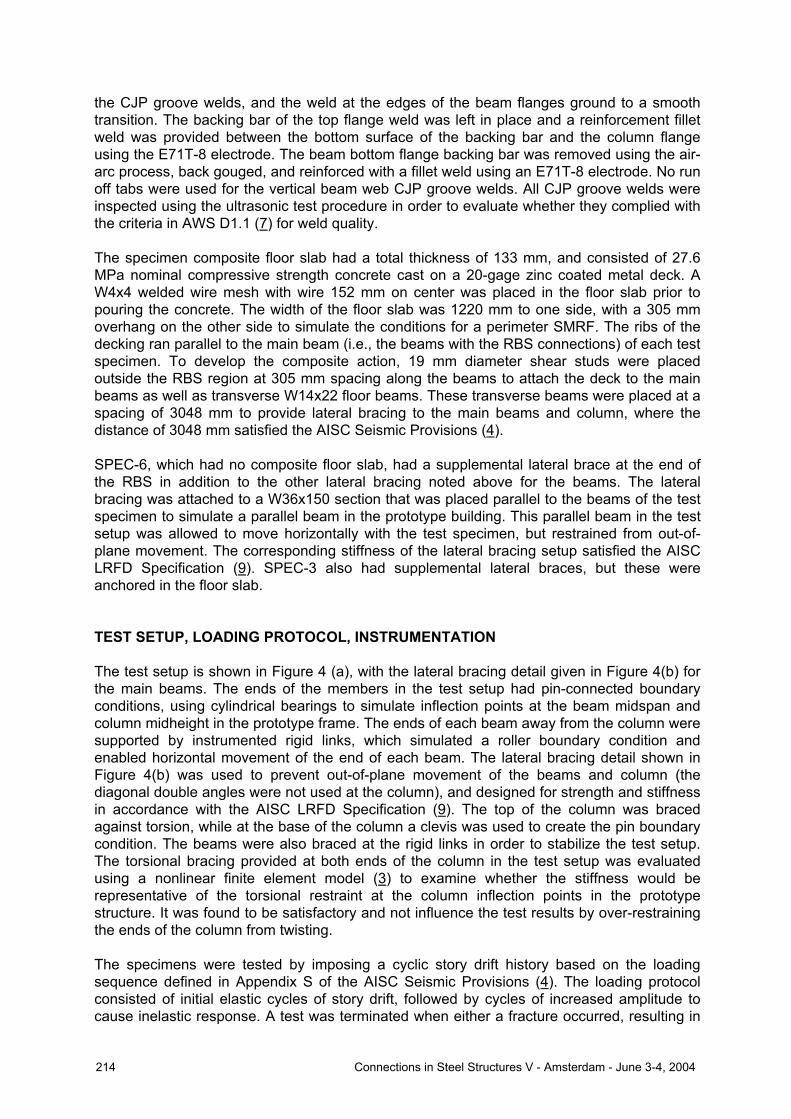
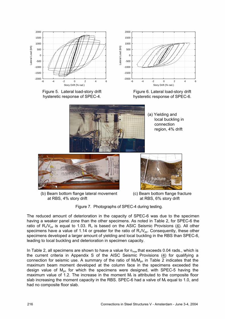
a significant loss of specimen capacity, or after reaching a story drift of 6%. Each specimen was instrumented to enable measurement of the applied loads, reactions at the rigid links, specimen story drift; strains in the beam, column, panel zone, and continuity plates; in addition to panel zone deformation, plastic beam rotation, twisting of the column, and lateral displacement of the beam at the center of the RBS. TEST RESULTS A summary of test results for each specimen is given in Table 2, where Rv/Vpz, θmax, Mf/Mpn, Kφ,col, φ, δflg, and bf are equal to the ratio of panel zone shear capacity-to-panel zone shear force corresponding to the plastic flexural moment developing in the RBS, specimen drift from the last cycle prior to any fracture or strength deterioration to below 80% of the specimen nominal capacity, ratio of maximum measured beam moment developed at the column face-to-nominal beam flexural capacity, column elastic torsional stiffness, specimen column twist at 4% story drift, lateral displacement of the beam bottom flange at the RBS at 4% story drift, and beam flange width, respectively. Typical observed behavior during the testing of a specimen consisted of yielding in the RBS and the panel zone, followed by cyclic local web and flange buckling in the RBS. Following the development of local bucking in the RBS, lateral movement of the bottom beam flange began to occur in the RBS of specimens with a composite floor slab at 2% to 3% story drift. The combined effect of cyclic local buckling and lateral flange displacement resulted in a gradual deterioration in specimen capacity to occur during subsequent cycles where the story drift amplitude was increased. This is evident in the lateral load-story drift hysteretic response of SPEC-4 shown in Figure 5. The lateral displacement of the bottom beam flange occurred when it was in compression, and caused some column twist to develop. Figure 7(a) and (b) shows photographs of SPEC-4 at 4% and 6% story drift, where the yielding in the members and panel zone in the connection region and lateral beam flange movement in the RBS are visible. The maximum column twist among the specimens with a floor slab at 4% story drift was 0.037 rads. (SPEC-4). 4% story drift is the drift at which connections are judged for qualification for seismic use by the AISC Seismic Provisions (4). SPEC-4, like the other specimens, developed a flange fracture in the RBS where extensive local flange buckling had occurred (see Figure 7(c)). This occurred at a story drift of 6%, and was caused by local buckling in the beam flange that led to large cyclic strains, resulting in a low cycle fatigue failure. SPEC-6, which had a supplemental brace and lateral bracing attached to the beam that is parallel to the test beam, had minimal deterioration in capacity as well as column twist (0.004 rads. at 4% story drift), see Figure 6.
Figure 4. (a) Test setup and (b) beam lateral bracing detail for specimens with a composite floor slab (Note: 1 inch = 25.4 mm).
6'-6
"
29'-6"14'-9"
Setup Lateral Bracing
Beam Web Stiffener withDiagonal Brace to Floor Beam (North Side Only)
Load Cell
14'-9"
Load Cell
131 2"
Beam (East) Beam (West)
6'-6
"
1312"
10'10'
(North Side Only) (North Side Only)Floor BeamFloor Slab 131
2"No Diagonal Bracing
Floor Beam21
"Column
ActuatorLoad Cell
LCSYM
Floor Slab
W14x22
Shear Stud48"
A325 3 4" diam.
(TYP)W36x150
51 4"
12"
Double Angle2 L2x2x5
16
(b) (a)
Connections in Steel Structures V - Amsterdam - June 3-4, 2004 215
The reduced amount of deterioration in the capacity of SPEC-6 was due to the specimen having a weaker panel zone than the other specimens. As noted in Table 2, for SPEC-6 the ratio of Rv/Vpz is equal to 1.03. Rv is based on the ASIC Seismic Provisions (4). All other specimens have a value of 1.14 or greater for the ratio of Rv/Vpz. Consequently, these other specimens developed a larger amount of yielding and local buckling in the RBS than SPEC-6, leading to local buckling and deterioration in specimen capacity. In Table 2, all specimens are shown to have a value for θmax that exceeds 0.04 rads., which is the current criteria in Appendix S of the AISC Seismic Provisions (4) for qualifying a connection for seismic use. A summary of the ratio of Mf/Mpn in Table 2 indicates that the maximum beam moment developed at the column face in the specimens exceeded the design value of Mpn for which the specimens were designed, with SPEC-5 having the maximum value of 1.2. The increase in the moment Mf is attributed to the composite floor slab increasing the moment capacity in the RBS. SPEC-6 had a valve of Mf equal to 1.0, and had no composite floor slab.
Figure 5. Lateral load-story drift hysteretic response of SPEC-4.
-2000
-1500
-1000
-500
0
500
1000
1500
2000
-6 -4 -2 0 2 4 6
Late
ral L
oad
(kN
)
Story Drift (% rad.)
Figure 6. Lateral load-story drift hysteretic response of SPEC-6.
-2000
-1500
-1000
-500
0
500
1000
1500
2000
-6 -4 -2 0 2 4 6
Late
ral L
oad
(kN
)
Story Drift (% rad.)
(a) Yielding and local buckling in connection region, 4% drift
fracture
(c) Beam bottom flange fracture at RBS, 6% story drift
(b) Beam bottom flange lateral movement at RBS, 4% story drift
Figure 7. Photographs of SPEC-4 during testing.
216 Connections in Steel Structures V - Amsterdam - June 3-4, 2004
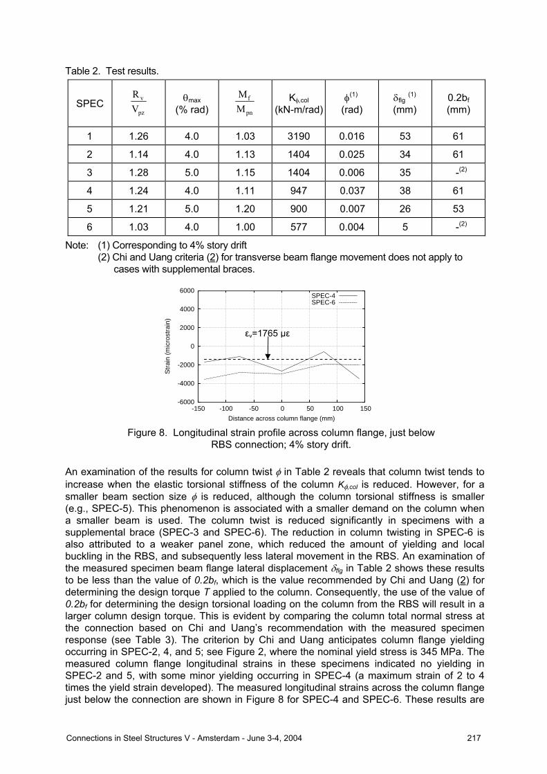
Table 2. Test results.
SPEC pz
v
VR θmax
(% rad) pn
f
MM Kφ,col
(kN-m/rad)φ(1)
(rad) δflg (1) (mm)
0.2bf (mm)
1 1.26 4.0 1.03 3190 0.016 53 61
2 1.14 4.0 1.13 1404 0.025 34 61
3 1.28 5.0 1.15 1404 0.006 35 -(2)
4 1.24 4.0 1.11 947 0.037 38 61
5 1.21 5.0 1.20 900 0.007 26 53
6 1.03 4.0 1.00 577 0.004 5 -(2)
Note: (1) Corresponding to 4% story drift (2) Chi and Uang criteria (2) for transverse beam flange movement does not apply to cases with supplemental braces. An examination of the results for column twist φ in Table 2 reveals that column twist tends to increase when the elastic torsional stiffness of the column Kφ,col is reduced. However, for a smaller beam section size φ is reduced, although the column torsional stiffness is smaller (e.g., SPEC-5). This phenomenon is associated with a smaller demand on the column when a smaller beam is used. The column twist is reduced significantly in specimens with a supplemental brace (SPEC-3 and SPEC-6). The reduction in column twisting in SPEC-6 is also attributed to a weaker panel zone, which reduced the amount of yielding and local buckling in the RBS, and subsequently less lateral movement in the RBS. An examination of the measured specimen beam flange lateral displacement δflg in Table 2 shows these results to be less than the value of 0.2bf, which is the value recommended by Chi and Uang (2) for determining the design torque T applied to the column. Consequently, the use of the value of 0.2bf for determining the design torsional loading on the column from the RBS will result in a larger column design torque. This is evident by comparing the column total normal stress at the connection based on Chi and Uang’s recommendation with the measured specimen response (see Table 3). The criterion by Chi and Uang anticipates column flange yielding occurring in SPEC-2, 4, and 5; see Figure 2, where the nominal yield stress is 345 MPa. The measured column flange longitudinal strains in these specimens indicated no yielding in SPEC-2 and 5, with some minor yielding occurring in SPEC-4 (a maximum strain of 2 to 4 times the yield strain developed). The measured longitudinal strains across the column flange just below the connection are shown in Figure 8 for SPEC-4 and SPEC-6. These results are
-6000
-4000
-2000
0
2000
4000
6000
-150 -100 -50 0 50 100 150
Str
ain
(mic
rost
rain
)
Distance across column flange (mm)
SPEC-4SPEC-6
Figure 8. Longitudinal strain profile across column flange, just below RBS connection; 4% story drift.
εy=1765 µε
Connections in Steel Structures V - Amsterdam - June 3-4, 2004 217

representative of typical specimen behavior, and show little evidence of a strain gradient across the flange that would result from the effects of warping normal stresses due to column torsion. DESIGN RECOMMENDATIONS The strains in the beam bottom flange near the column face were examined to evaluate the stress distribution across the beam flange that leads to a torque T applied to the column. Shown below in Figure 9(a) is the distribution of longitudinal stress across the beam bottom flange at 4% story drift. These stresses are based on measured longitudinal strains in the specimens. These results correspond to a negative beam moment at the column face (i.e., when the bottom flange of the beam is in “compression”). Similar results for longitudinal stress across the beam compression flange were obtained from finite element studies (see Figure 9(b)). The results in Figure 9 show a trend where the stress distribution across the beam flange has a reduction in stress, which is due to a moment in the plane of the beam flange caused by the lateral movement of the beam flange at the RBS. This moment is equivalent to the torque T that is applied by the beam flange to the column. Shown in Figure 10(a) is an idealized uniform longitudinal stress distribution prior to lateral movement of the beam flange in the RBS (at 2% story drift). The idealized longitudinal stress distribution at 4% story drift based on the measured and finite element analysis results is given in Figure 10(b). At 4% drift local buckling and lateral beam flange movement has occurred in the RBS. Elastic-perfectly stress-strain behavior is assumed in Figure 10, where Fye is the yield stress.
-500
-400
-300
-200
-100
0
100
-150 -100 -50 0 50 100 150
Long
itudi
nal s
tres
s (M
Pa)
Distance across beam flange (mm)
-400
-300
-200
-100
0
100
200
300
400
-150 -100 -50 0 50 100 150
Str
ess
(MP
a)
Distance across beam flange (mm)
SPEC-1SPEC-2SPEC-3SPEC-4SPEC-5
Figure 9. Longitudinal stress distribution across beam flange for (a) all test specimens, and (b) finite element analysis of SPEC-2.
(a)
(b)
(a) (b)
Figure 10. Idealized longitudinal stress distribution across beam bottom flange at (a) 2% story drift and (b) 4% story drift.
Fye Fye
218 Connections in Steel Structures V - Amsterdam - June 3-4, 2004

For the longitudinal stress distribution shown in Figure 10(b), T can be shown (3) to be equal to
f2fye tbF
15011T = (1)
where Fye, bf, and tf are equal to the expected beam flange yield stress (1.1Fy), the beam flange width, and beam flange thickness, respectively. A design procedure was thus developed in order to determine the total design longitudinal stress ftotal in the column flange that is attached to an RBS connection. The procedure involves determining the elastic warping normal stresses fw that develop in the column flange due to the torque T (10) and superimposing them with the column flange normal stresses due to bending (fb) and axial loading (fa) to obtain the total normal stress ftotal, where "
w θnOEWf = (2) In Equation (2) E, WnO, and θ” are equal to the Young’s modulus, normalized warping function at the column flange tip (10), and the second derivative of the angle of twist in the column (10), respectively, where θ” is a function of the torque T. The total stress ftotal is compared to the criteria in the AISC LRFD Specification (9), Equation (H2-1), where yFf φ=total (3) in which φ and Fy are the resistance factor (0.9) and nominal yield stress of the column flange, respectively. The above design procedure is similar to that developed by Chi and Uang (2), except for the method in which the torque is determined. Table 3. Comparison of column normal flange compression stresses with design procedure.
Warping stress fw (MPa)
Total normal stress ftotal (MPa)
Experimental results, total
stress & strain, 4% story drift SPEC Column Beam
Axial load
stress fa
(MPa)
Bending stress
fb (MPa) Chi and
Uang
Pro-posed
Chi and
Uang
Pro-posed
Strain (µε)
Stress (MPa)
1 W36x230 0 190 128 66 318 256 1277 255
2 W27x194 0 299 182 101 481 400 2151 372(1)
3 W27x194 0 332 0 0 332 332 1797 356(1)
4 W36x150
W36x150
0 337 321 163 658 500 3296 365(1)
5 W27x146 0 252 180 95 432 347 1598 319
6 W24x131 W30x108
0 347 0 0 347 347 2525 334(1)
Note: (1) Yield stress of the column flange. The total normal column flange stress based on the above procedure is compared in Table 3 to the measured stress of the test specimens, as well as the stress predicted using the procedure by Chi and Uang (2). The comparisons in Table 3 indicate that a more accurate prediction of the total normal stress in the column flange is made using the above procedure compared to the procedure developed by Chi and Uang (2). The difference between the two
Connections in Steel Structures V - Amsterdam - June 3-4, 2004 219
methods is the normal warping stress fw predicted by the above procedure is based on a more accurate value of the torque T applied to the column. For specimens with a supplemental lateral brace it was assumed that the restraint of the supplemental brace resulted in no torque applied to the column (i.e., the normal warping stress fw is equal to zero). This results in a lower predicted stress than the measured response. SUMMARY AND CONCLUSIONS An experimental program was conducted in order to evaluate the seismic performance of RBS connections to deep wide flange columns. The study involved testing six full-scale specimens to evaluate the effects of column depth, beam size, composite floor slab, and a supplemental lateral brace. Based on the experimental study, the following main conclusions are noted:
1. A composite floor slab can significantly reduce the lateral displacement of the beam bottom flange in the RBS and the amount of twist developed in the column. The slab appears to be effective in reducing the twist in deeper columns attached to an RBS connection, and enables the cyclic strength of the beam with an RBS connection to be better sustained.
2. All of the specimens were able to satisfy the criteria in the AISC Seismic Provisions (4) for qualifying the connection for seismic use.
3. A weaker panel zone in a deep column RBS connection will not develop as much column twist and strength degradation as a connection with a stronger panel zone. However, a weaker panel zone can significantly increase the potential for ductile fracture of the connection (3). It is recommended that connections be designed with a balanced panel zone strength condition.
4. A supplemental brace at the end of the RBS significantly reduced the transverse movement of the beam flanges in the RBS and column twist that leads to cyclic degradation in specimen capacity.
5. Basing the column torque on a transverse movement of the beam flange in the RBS of 0.2bf for calculating column flange warping stresses appears to be conservative. A new procedure for estimating the torsional load applied to the column due to the local and lateral buckling in the RBS shows improvement in predicting the correct column flange normal stress.
ACKNOWLEDGEMENTS The research reported herein was supported by a grant from the American Institute of Steel Construction (Mr. Tom Schlafly program manager) and from the Pennsylvania Department of Community and Economic Development through the Pennsylvania Infrastructure Technology Alliance (PITA) program. The following companies donated materials for the experimental testing conducted in this research project: Arcelor International America of New York, NY (steel sections); Nucor Vulcraft Group of Chemung, NY (metal decking); and the Lincoln Electric Company of Cleveland, OH (welding wire). The support provided by the funding agencies and companies is greatly appreciated.
220 Connections in Steel Structures V - Amsterdam - June 3-4, 2004
REFERENCES (1) Roeder, C. W. (2000). “Connection Performance State of Art Report,” Report No.
FEMA-355D, FEMA, Washington, D.C. (2) Chi, B. and Uang, C.-M. (2002). “Cyclic Response and Design Recommendations of
Reduced Beam Section Moment Connections with Deep Columns,” Journal of Structural Engineering, ASCE, 128(4): 464-473.
(3) Ricles, J., Zhang, X., Lu, L.W., and J. Fisher, (2004). “Development of Seismic Guidelines for Deep-Column Steel Moment Connections,” ATLSS Report No. 04-13, ATLSS Engineering Research Center, Lehigh University, Bethlehem, PA.
(4) “Seismic Provisions for Structural Steel Buildings,” (2002). American Institute of Steel Construction, Chicago, Illinois.
(5) Engelhardt, M. D. (1999). “The 1999 T. R. Higgins Lecture: Design of Reduced Beam Section Moment Connections,” Proceedings: 1999 North American Steel Construction Conference, American Institute of Steel Construction, Toronto, Canada, pp. 1-1 to 1-29.
(6) “Recommended Specifications and Quality Assurance Guidelines for Steel Moment-Frame Construction for Seismic Applications,” (2000). Report No. FEMA 353, Federal Emergency Management Agency, Washington D. C.
(7) “Structural Welding Code – Steel,” (2002). AWS D1.1/D1.1M:2002, American Welding Society, Miami, Florida.
(8) “Specification for Carbon Steel Electrodes for Flux Cored Arc Welding,” (1995). ANSI/AWS A5.20-95, American Welding Society, Miami, Florida.
(9) “Manual of Steel Construction-Load and Resistance Factor Design,” (2001). Third Ed., AISC, Chicago, Illinois.
(10) Seaburg, P., and C. Carter, (1997). “Torsional Analysis of Structural Steel Members,” American Institute of Steel Construction Steel Design Guide Series, ASIC, Chicago, Illinois.
Connections in Steel Structures V - Amsterdam - June 3-4, 2004 221

222 Connections in Steel Structures V - Amsterdam - June 3-4, 2004