Evaluation of the Behavior of Flat Slab Systems Subjected ...

2034
Research Article
International Journal of Current Engineering and Technology ISSN 2277 - 4106
© 2013 INPRESSCO. All Rights Reserved.
Available at http://inpressco.com/category/ijcet
Seismic Load Analysis of different R.C. Slab Systems for Tall Building
Mohamed A. A. El-ShaerȦ*
ȦCivil and Construction Engineering Department, higher Technological Institute, 10th of Ramadan City
Accepted 18 December 2013, Available online 25 December 2013, Vol.3, No.5 (December 2013)
Abstract
This Paper introduced the lateral analysis for tall buildings due to the seismic performance for different reinforced
concrete slab systems. It study three systems, flat slab, ribbed slab, and panelled beam slab. The three systems are from
the most attractive and commonly used floor systems, especially in high-rise constructions. In high seismicity regions,
the declared non-ductile flat slab system poses a significant risk, brittle punching failure arises from the transfer of
shearing forces and unbalanced moments between slab and columns that may trigger a progressive building collapse.
This system is inherently flexible due to the non-rigid slab-column connections, and the building high aspect
(height/width) ratio. Hence, in regions of high seismic risk, design codes recommended the use of slab-column frames to
resist slabs, and require another stiffer system to resist lateral wind and seismic forces. From this standpoint, the choose
of a system that provide rigid concrete slab than flat slab to resist lateral wind and seismic forces. This system is chosen
to be the ribbed slab, and the panelled beam slab. These two systems of concrete slabs are ductile, and balanced
moments between slab and columns. As the different types of seismic load resisting systems generally presented. Then,
three systems of slabs performance for systems high-rise buildings during seismic loads are introduced. Some seismic
design, analysis and performance assessment aspects of flat slab, and ribbed slab, and panelled beams systems for high-
rise buildings are subsequently discussed. Finally, suggestions to improve the seismic performance of high - rise
buildings horizontal members in slabs (ribs or beams-column) buildings are presented. ETABS version 9.5 is for analysis
under lateral loads. ETABS is a programmer for linear, nonlinear, static and dynamic analysis, and the design of
building systems. Multistory buildings constitute a very special class of structures and therefore deserve special
treatment . The program is used to calculate the drifts for the systems and we noticed that the minimum drift was
occurred in the ribbed slab system. So that, in high seismic risk regions, ribbed-slab-column frames is recommended to
be gravity load resisting systems for building of high values of height/width ratios.
Keywords: Flat slab; Beam-column; Ribbed slab; Seismic load; Drift.
Introduction
1 The flat slab system since its inception in the USA by
Turner in 1906 has been gaining popularity all over the
world, as evidence of the large portion of the newly
constructed buildings which employ that system. Flat slab
systems in current construction practice are commonly
used for relatively light residential loads and for spans
from 4.5m to 6m. For heavy industrial or office building
loads and/or for larger spans, flat slabs are used with drop
panels or column capitals. The flat slab type of
construction provides architectural flexibility, more clear
space, less building height, easier formwork, and
consequently, shorter construction time. However, flat
slabs are susceptible to significant reductions in stiffness
as a consequence of slab cracking that can arise from
construction loads, service gravity loads, temperature and
shrinkage effects, and lateral loads. Due to their inherent
flexibility, flat slab/plate systems (especially in multi-story
* Corresponding author is working as Associate Professor
high-rise buildings) experience excessive lateral drifts
(displacement) when subjected to wind loads or seismic
excitations. Also they possess non-ductile overall
response, local seismic hysteretic response, and poor
energy dissipations. Furthermore, their potential of brittle
punching failure at the slab-column connections.
Therefore in regions of high seismic risk, modern seismic
design codes prohibit the use of flat slab/plate as a lateral
load resisting system, but allow its use as a vertical
(gravity) load resisting system.
After that, this paper introduces several systems that is
used in high rise building of 30 stories . Three types are
selected, flat slab , paneled beams and ribbed slab floor
systems , with the same lateral loads resistance systems
( core and shear wall system ).
Lateral Loads Resisting System
Lateral loads resisting system may be on or more of the
following systems:

Mohamed A. A. El-Shaer International Journal of Current Engineering and Technology, Vol.3, No.5 (December 2013)
2035
Braced frame, Rigid frame, Infilled frame, Shear walls,
Wall frame, Frame tube, Outrigger braced, Suspended,
Space structures, and Core system. The last system (Core
system) is the subject of the study in this search.
Response Analysis
The analysis of seismic response of tall buildings under
seismic loads can be carried out by one of the following
methods:
a- Elastic static analysis
This procedure is generally used in the preliminary stages
of planning the building, where the suitability for number
of choices for the lateral load resisting systems is being
investigated. The analysis is carried out on the system
model subject to the equivalent static seismic forces
b- Modal response spectrum
This procedure is more appropriate to flexible structures
where the first mode alone is not able to reasonably
represent the system response. Therefore, higher modes
(second, third, fourth, etc.) contribution to the response
shall be considered. This method is more appropriate for
high-rise buildings the previous method during the
preliminary planning process.
The different modes of vibrations and their frequencies
(or their natural periods of vibrations) are needed to
conduct the modal analysis. Therefore the free vibration
analysis of the lateral load resisting system shall be
performed prior to the modal response analysis.
c- Elastic dynamic time-history
The adequacy of the selected lateral load system for the
serviceability limit state shall be checked under earthquake
of 10 years return period. Seismic design codes require
the system to continue its elastic behavior and sustain no
damage, maintaining mits elastic behavior. It can also be
used to approximate the seismic response of the building
when subject to larger earthquakes of 50 years return
period, where the building is expected to suffer minor
structural damages.
Response Spectrum analysis for earthquakes
In order to perform the seismic analysis and design of a
structure to be built at a particular location, the actual time
history record is required. However, it is not possible to
have such records at each and every location. Further, the
seismic analysis of structures cannot be carried out simply
based on the peak value of the ground acceleration as the
response of the structure depend upon the frequency
content of ground motion and its own dynamic properties.
To overcome the above difficulties, earthquake response
spectrum is the most popular tool in the seismic analysis
of structures. There are computational advantages in using
the response spectrum method of seismic analysis for
prediction of displacements and member forces in
structural systems. The method involves the calculation of
only the maximum values of the displacements and
member forces in each mode of vibration using smooth
design spectra that are the average of several earthquake
motions.
This paper deals with response spectrum method and
its application to various types of the structures.
Response spectra are curves plotted between maximum
response of SDOF system subjected to specified
earthquake ground motion and its time period (or
frequency) as in figure (1). Response spectrum can be
interpreted as the locus of maximum response of a SDOF
system for given damping ratio. Response spectra thus
helps in obtaining the peak structural responses under
linear range, which can be used for obtaining lateral forces
developed in structure due to earthquake thus facilitates in
earthquake-resistant design of structures.
Usually response of a SDOF system is determined by
time domain or frequency domain analysis, and for a given
time period of system, maximum response is picked. This
process is continued for all range of possible time periods
of SDOF system. Final plot with system time period on x-
axis and response quantity on y-axis is the required
response spectra pertaining to specified damping ratio and
input ground motion. Same process is carried out with
different damping ratios to obtain overall response spectra.
Consider a SDOF system subjected to earthquake
acceleration, the equation of motion is given by:
)()()()( tg
xmtkxtxctxm Eq.(1)
Where ;
)(txm : is mass times acceleration;
)(txc : is the damping term and equals to zero for
undamped motion;
)(tkx : displacement times stiffness.
Fig.1 Response spectra curve
Substitute mKo / and om
c
2 and
21 od
Where :
Mohamed A. A. El-Shaer International Journal of Current Engineering and Technology, Vol.3, No.5 (December 2013)
2036
o : circular frequency;
: damping ratio.
Therefore ; eq.1 can be written
)()()(2)( 2 txtxtxtx goo
Using Duhamel’s integral, the solution of SDOF system
initially at rest is given by (Agrawal and Shrikhande,
2006), [20]
T
dns
d
to
g dtie
xtx0
)(
)()()(
The maximum displacement of the SDOF system having
parameters of ξ and ω0 and subjected to specified
earthquake motion, is expressed by )(txg .
The relative displacement spectrum of earthquake ground
motion is defined as,
max0
)(
max)()()(
t
dns
d
tow
g dtie
xtx
max)(),( txs od
Similarly, the relative velocity spectrum, Sv and absolute
acceleration response spectrum, Sa are expressed as,
max)(),( txs ov
maxmax)()()(),( txtxtxs gaoa
The pseudo velocity response spectrum, Spv for the system
is defined as
max)(),( txs od
Similarly, the pseudo acceleration response, Spa is obtained
by multiplying the Sd to 2
0 , thus
),(),( 2
odoopa ss Eq.(2)
0 i.e )()()( 2 txtxtsx go
Consider a case where
max)()( txtxs ga
max
2
0 )(tx max
2
0 xds2
0 pas
The above equation implies that for an undamped system,
Sa = Spa.
The quantity Spv is used to calculate the maximum strain
energy stored in the structure expressed as
222
0
2
maxmax2
1
2
1
2
1pvd
mssmKxE Eq.(3)
The quantity Spa is related to the maximum value of base
shear as
pad mssmKxV 2
0maxmax Eq.(4)
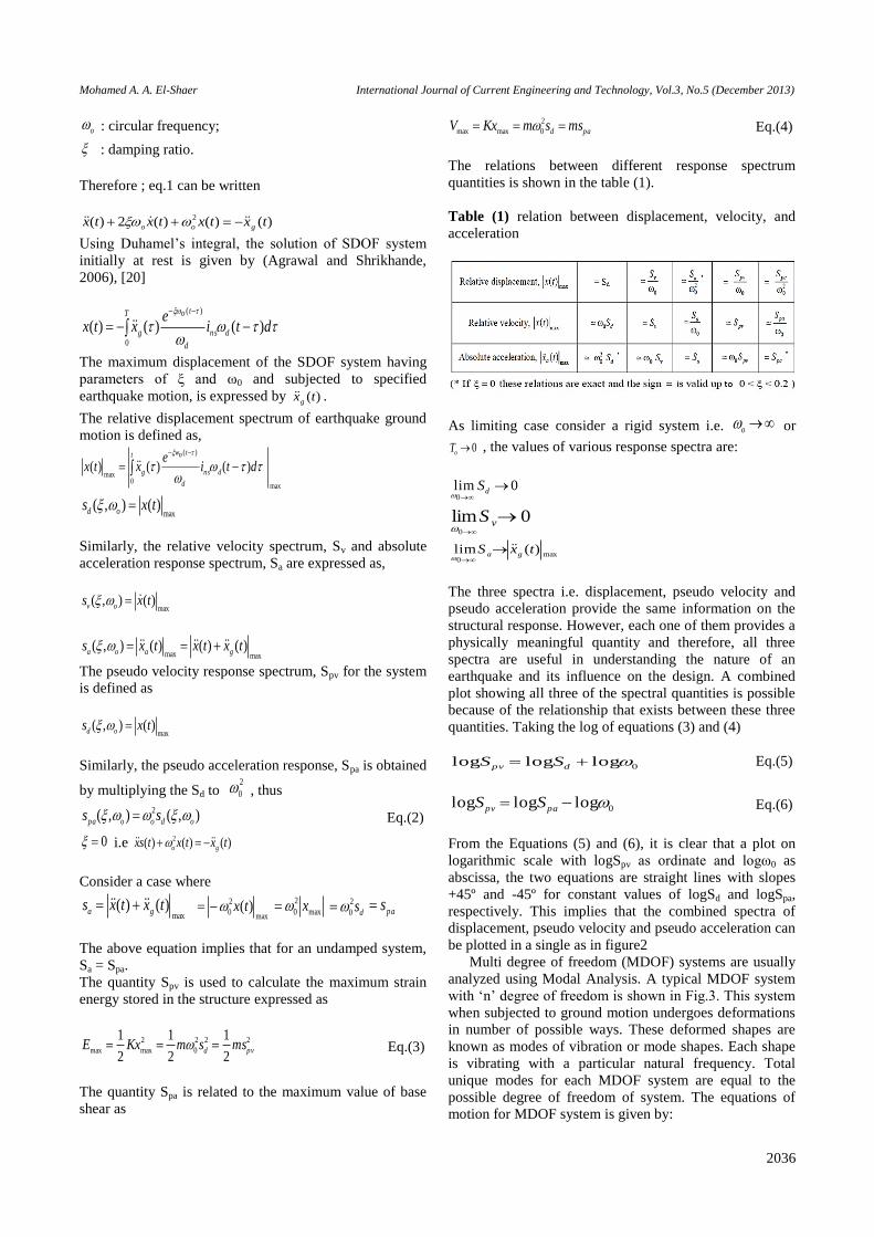
The relations between different response spectrum
quantities is shown in the table (1).
Table (1) relation between displacement, velocity, and
acceleration
As limiting case consider a rigid system i.e. o or
0oT , the values of various response spectra are:
0lim0
dS
0lim0
vS
max0
)(lim txS ga
The three spectra i.e. displacement, pseudo velocity and
pseudo acceleration provide the same information on the
structural response. However, each one of them provides a
physically meaningful quantity and therefore, all three
spectra are useful in understanding the nature of an
earthquake and its influence on the design. A combined
plot showing all three of the spectral quantities is possible
because of the relationship that exists between these three
quantities. Taking the log of equations (3) and (4)
0logloglog dpv SS Eq.(5)
0logloglog papv SS Eq.(6)
From the Equations (5) and (6), it is clear that a plot on
logarithmic scale with logSpv as ordinate and logω0 as
abscissa, the two equations are straight lines with slopes
+45º and -45º for constant values of logSd and logSpa,
respectively. This implies that the combined spectra of
displacement, pseudo velocity and pseudo acceleration can
be plotted in a single as in figure2
Multi degree of freedom (MDOF) systems are usually
analyzed using Modal Analysis. A typical MDOF system
with ‘n’ degree of freedom is shown in Fig.3. This system
when subjected to ground motion undergoes deformations
in number of possible ways. These deformed shapes are
known as modes of vibration or mode shapes. Each shape
is vibrating with a particular natural frequency. Total
unique modes for each MDOF system are equal to the
possible degree of freedom of system. The equations of
motion for MDOF system is given by:

Mohamed A. A. El-Shaer International Journal of Current Engineering and Technology, Vol.3, No.5 (December 2013)
2037
)(}{)}({)}({)}({ txrmtxKtoxctxm g Eq.(7)
where, [m] = Mass matrix (n × n); [k] = Stiffness matrix (n
× n); [c] = Damping matrix (n × n); {r} = Influence
coefficient vector (n×1); {x(t)} = relative displacement
vector; )(tx = relative velocity vector, )(tx = relative
acceleration vector, and )(txg = earthquake ground
acceleration.
Fig.2 Spectra of displacement, pseudo velocity and pseudo
acceleration
Fig.3 A typical MDOF system with ‘n’ degree of freedom
The undamped eigen values and eigen vectors of the
MDOF system are found form the
characteristic equation
0]}[{ 2 ii mK i=1,2,3,…,n Eq.(8)
0]}[]{[det 2 mK i Eq(9)
where, 2
i eigen values of the ith mode;
i eigen vector or mode shape of the ith mode;
i natural frequency in the ith mode.
Let the displacement response of the MDOF system is
expressed as
)}(]{[)}({ tytx Eq.(10)
where {y(t)} represents the modal displacement vector,
and [φ] is the mode shape matrix
given by
]..,.........,[][ 21 n
Substituting )}(]{[)( tytx in eq.7 and pre-multiply by
)(}]{[][)}(]{][[][)(]{][[][)}(]{][[][ txrmtyKtyctym g
TTTT
The above equation reduces to
)(}]{[][)}(]{[)}(]{[)}({][ txrmtyKtyctyM g
T
ddm
Eq.(11)
Where ;
][]][[][ m
T Mm generalized mass matrix;
][]][[][ d
T cc generalized damping matrix;
][]][[][ d
T KK generalized stiffness matrix.
By virtue of the properties of the [φ], the matrices [Mm]
and [Kd] are diagonal matrices.
However, for the classically damped system (i.e. if the
[Cd] is also a diagonal matrix), the
Eq.11 reduces to the following equation;
)()()(2)( 2 txtytyty giiiiiii (i=1,2,3,….,n) Eq.(12)
where,
)(tyi modal displacement response in the ith mode;
i modal damping ration in the ith mode;
i modal participation factor for ith mode expressed by
}]{[}{
}]{[}{
i
T
i
T
i
im
rm
eq.12 is of the form of eq.1 representing vibration of
SDOF system, the maximum modal displacement response
is found from the response spectrum i.e.
),()(maxmax, iidiii styy Eq.(13)
The maximum displacement response of the structure in
the ith mode is
max,max, iii yx (i=1,2,……..,n) Eq.(14)
The maximum acceleration response of the structure in the
ith mode is
),(}{}{ max, iipaiiia sx (i=1,2,……..,n) Eq.(15)

Mohamed A. A. El-Shaer International Journal of Current Engineering and Technology, Vol.3, No.5 (December 2013)
2038
Fig. 3 Flat slab plan system
The required response quantity of interest, ri i.e.
(displacement, shear force, bending moment etc.) of the
structure can be obtained in each mode of vibration using
the maximum response obtained in eq.14 and eq.15.
However, the final maximum response, rmax shall be
obtained by combining the response in each mode of
vibration using the modal combinations rules.
A- Flat slab floor
For the lower range of high-rise flat slab/plate buildings
(up to15 stories), the framing action of the slab-columns
can provide the necessary stiffness and strength to resist
wind and seismic forces. Flat slab/plate -columns subject
to lateral loads are analyzed as unbraced two-dimensional
equivalent frames using two methodologies; the torsional
member method and the effective slab width method. Our
Flat slab system consists of a flat plate 28.00 cm resting on
five models of columns with marginal beam of 90cm. The
slab was checked against deflection, flexural and punching
stresses and it was fully safe.
B- Panelled beams floor
Panelled beams slab system consists of thin two way solid
slabs 10-12 Cm thickness rested on rigid pannelled beams
30 85 Cm sectional area working by grid action where
each beam works as an elastic support for the other at the
intersection area between them. The paneled beams are
supported on external beams 40 90 Cm sectional area.

Mohamed A. A. El-Shaer International Journal of Current Engineering and Technology, Vol.3, No.5 (December 2013)
2039
Fig. 4 Panelled beams slab plan system

Mohamed A. A. El-Shaer International Journal of Current Engineering and Technology, Vol.3, No.5 (December 2013)
2040
Fig. 5.a Ribbed slab plan system
Fig. 5.b Beams & Ribs details for Ribbed slab
Analysis Procedure
There are three models of a residential building of 30
stories and total area of 1313.55 m2, the three models
(Core system) represent flat slab system, pannelled beams
system, ribbed slab system respectively. This systems of
slabs were fabricated and analysis by ETABS 9.5 in the
current study. All models have the same architecture plan
and the same columns sections and also the same area,
figure 2 represents the 3D – models from ETABS
program.

Mohamed A. A. El-Shaer International Journal of Current Engineering and Technology, Vol.3, No.5 (December 2013)
2041
Fig. 6 ETABS 3-D model
Detected Response Parameters from ETABS 9.5
Detected INTER STORY DRIFT in the three systems
Drift ratio is the ratio between drift and building height in
percent, and the inter-story drift ratio is the ratio between
the change of drift in the story and the story height.
Fig. 7 Inter Story Drift in X-direction for Flat slab system
Fig. 8 Inter Story Drift in Y-direction for Flat slab system
B-For Pannelled beams system
Fig. 9 Inter Story Drift in X-direction for Pannelled beams
system
Fig. 10 Inter Story Drift in Y-direction for Pannelled
beams system

Mohamed A. A. El-Shaer International Journal of Current Engineering and Technology, Vol.3, No.5 (December 2013)
2042
C- For Ribbed slab system
Fig. 11 Inter Story Drift in X-direction for Ribbed slab
system
Fig. 12 Inter Story Drift in Y-direction for Ribbed slab
system
2- Detected BASE SHEAR in the three systems
A- For Flat slab system
Fig. 13 Base Shear in X-direction for Flat slab system
Fig. 14 Base Shear in Y-direction for Flat slab system
B- For Pannelled beams system
Fig. 15 Base Shear in X-direction for Pannelled beams
system
Fig. 16 Base Shear in Y-direction for Pannelled beams
system

Mohamed A. A. El-Shaer International Journal of Current Engineering and Technology, Vol.3, No.5 (December 2013)
2043
C- For Ribbed slab system
Fig. 17 Base Shear in X-direction for Ribbed slab system
Fig. 18 Base Shear in Y-direction for Ribbed slab system
3 - Detected OVERTURNING MOMENT in the three
systems
A- For Flat slab system
Fig. 19 Overturning Moment in X-direction for Flat slab
system
Fig. 20 Overturning Moment in Y-direction for Flat slab
system
B- For Pannelled beams system
Fig. 21 Overturning Moment in X-direction for Pannelled
beams system
Fig. 22 Overturning Moment in Y-direction for Pannelled
beams system
Mohamed A. A. El-Shaer International Journal of Current Engineering and Technology, Vol.3, No.5 (December 2013)
2044
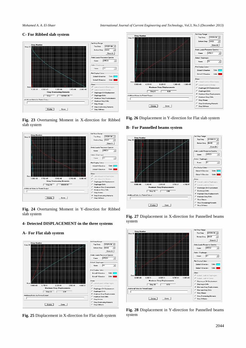
C- For Ribbed slab system
Fig. 23 Overturning Moment in X-direction for Ribbed
slab system
Fig. 24 Overturning Moment in Y-direction for Ribbed
slab system
4- Detected DISPLACEMENT-in the three systems
A- For Flat slab system
Fig. 25 Displacement in X-direction for Flat slab system
Fig. 26 Displacement in Y-direction for Flat slab system
B- For Pannelled beams system
Fig. 27 Displacement in X-direction for Pannelled beams
system
Fig. 28 Displacement in Y-direction for Pannelled beams
system

Mohamed A. A. El-Shaer International Journal of Current Engineering and Technology, Vol.3, No.5 (December 2013)
2045
C- For Ribbed slab system
Fig. 29 Displacement in X-direction for Ribbed slab
system
Fig. 30 Displacement in Y-direction for Ribbed slab
system
Analytical Results and Discussion
Results of the analysis three systems of slabs are
presented, analyzed and discussed in this section. Topics
to be covered include the Inter Story Drift, the Base Shear,
Overturning Moment, and Displacement in two directions
X and Y of the analysis systems. Tables from 2 to 5 lists
the results.
Table (2): Inter Story Drift in X&Y-direction for three
systems
Direction Flat slab Pannelled beams Ribbed slab
(m)X 0.00545 0.00488 0.00238
(m)Y 0.0202 0.0156 0.0153
Table (3): Base Shear in X&Y-direction for three systems
Direction Flat slab Pannelled beams Ribbed slab
(KN)X 36800 36600 36600
(KN)Y 36700 36700 36700
Table (4): Overturning Moment in X&Y-direction for
three systems
Direction Flat slab Pannelled beams Ribbed slab
YX
(KN.m) 2630000 2740000 2630000
(KN.m) 3180000 3080000 3080000
Table (5): Displacement in X&Y-direction for three
systems
Direction Flat slab Pannelled beams Ribbed slab
(m)X 0.466 0.415 0.202
(m)Y 1.68 1.3 1.29
The seismic response parameters of buildings are the
structure deformations (displacements and rotations),
internal forces in structural elements, and ductility
demand of members with plastic behavior.
Top story lateral displacement (drift) and the inter-
story lateral displacement (story drift) are the seismic
response parameter of prime importance for systems of
slabs in high rise buildings. Large values of drift could
affect the stability and resistance of tall buildings.
The system of Ribbed slab reduced the inter-story drift
by 56% than the system of flat slab and by 51% than the
system of Pannelled beams in the main direction (X
direction). And the system of Ribbed slab reduced the
Displacement by 57% than the system of flat slab and by
51% than the system of Pannelled beams in the main
direction (X direction).
Conclusions
Based on the results the following conclusions could be
drawn:
1- The choice of the system for slab in the tall bilding is
very important to resist the internal forces and
stability.
2- The system of Ribbed slab reduced the inter-story
drift, and Displacement by grater than 51% for core
system.
3- The Ribbed slab system resist the punching shear
failures, and increase the ductility capacity.
4- The flat slab cases, large inter-story drift which cause
brittle punching shear failures, reduces the ductility
capacity
References Gasparini, D. (2002). Contributions of C. A. P. Turner to
Development of Reinforced Concrete Flat Slabs 1905–1909.
J. Struct.
Pan, A. and Moehle, J. P. (1989). Lateral Displacement Ductility
of R/C Flat Plates. ACI Structural Journal.
Esteva, L., The Mexico City Earthquake of Sept. 19, 1985-
Consequences, Lessons, and Impact on Research and
Practice, Earthquake Spectra Vol. 4, No. 3, pp. 413-425,
Oakland, CA, USA, 1988.
Bertero, V. V. (1989), Lessons Learned from the 1985 Mexico
Earthquake, EERI, El Cerrito, CA, USA.

Mohamed A. A. El-Shaer International Journal of Current Engineering and Technology, Vol.3, No.5 (December 2013)
2046
Aguilar, J. A. (Dec 1995), Case Studies of Rehabilitation of
Existing Reinforced Concrete Buildings in Mexico City,
Master Thesis, Faculty of the Graduate School, University of
Texas at Austin, USA.
Comartin, C. D., Editor (April 1995), Guam Earthquake of
August 8, 1993 Reconnaissance Report, Supplement B to
Vol. 11, Earthquake Spectra, Oakland, CA, USA.
Holmes, W. T., and Somers, P., Editor, (Jan 1996) Northridge
Earthquake of January 17, 1994 Reconnaissance Report,
Supplement C to Vol. 11, Earthquake Spectra, Oakland, CA,
USA.
Kato, H., Tajiri, S., and Mukai, T. (2010), Preliminary
Reconnaissance Report of the Chile Earthquake 2010,
Building Research Institute, Japan.
AIJ, RCD (July 2011)Preliminary Reconnaissance Report of the
2011 Tohoku - Chiho Taiheiyo - Oki Earthquake, Research
Committee on Disaster, Architectural Institute of Japan.
ICC (2009), International building code, (IBC), International
Code Council. Birmingham, AL.
EUROCODE 8, (EC8) (2004), Design Provision for Earthquake
Resistance of Structures. EN 1998-1-1.
NBCC (1990), The National Building Code of Canada ,
Canada.
FEMA, NEHRP (2003), Recommended Provisions for Seismic
Regulations for New Buildings and Other Structures (FEMA
450), Washington, DC, USA.
FEMA, NEHRP (2006), Recommended Provisions: Instructional
and Training Materials, (FEMA 451B), Washington, DC,
USA.
ACI-318-08 (2008), Building code requirements for structural
concrete and Commentary, ACI Committee 318, American
Concrete Institute, Farmington Hills, Michigan, USA.
ECLF, Egyptian Code for Loads and Forces on Buildings and
Structures, Egypt, 2008.
Rizk, A. S. S. (2010), Structural Design of Reinforce Concrete
Tall Buildings, CTBUH Journal, Issue 1, pp 34–41, USA.
Sindel, Z., Akbag, R., and Texan, S. S. (1996), Drift Control and
Damage in Tall Buildings, Engineering Structures, Vol. 18,
No. 12, pp. 951-966, Elsevier Science, Great Britain.
Yang, T. Y., Bozorognia, Y., Moehle, J. P.(2008), The Tall
Building Initiative, 14th World Conference on Earthquake
Engineering October 12-17, Beijing, China.
Pankaj Agrawal, Manish Shrikhande (2006), Earthquake
Resistant Design of Structures.
Author’s Profile
Associate Professor, Civil and
Construction Engineering
Department, Higher Technological
Institute, 10th of Ramadan City, Head
of the Civil Engineering Department,
Head of Board of Directors of the
ELSHAER CONSULTANT GROUP,
and Consultant of the Ministry of
Housing, Utilities and Urban
Development, EGYPT.