
Seismic evaluation of mixed steel and RC columns in hybrid ...
15
SEISMIC EVALUATION OF MIXED STEEL AND RC COLUMNS IN HYBRID HIGH-RISE BUILDINGS D.-P. N. KONTONI 1 , A. A. FARGHALY 2 The growth in high-rise building construction has increased the need for hybrid reinforced concrete and steel structural systems. Columns in buildings are the most important elements because of their seismic resistance. Reinforced concrete (RC) columns and steel columns were used herein to form hybrid structural systems combining their distinct advantages. Eleven 3D building models subjected to earthquake excitation with reinforced concrete beams and slabs of 12 floors in height and with different distributions of mixed columns were analyzed by the SAP2000 software in order to investigate the most suitable distributions of a combination of reinforced concrete and steel columns. Top displacements and accelerations, base normal forces, base shear forces, and base bending moments were computed to evaluate the selected hybrid structural systems. The findings are helpful in evaluating the efficiency of the examined hybrid high-rise buildings in resisting earthquakes. Keywords: High-rise buildings, Hybrid RC-steel buildings, RC beams and slabs, RC columns, Steel columns, Seismic response, Earthquake resistant structures. 1. INTRODUCTION Concrete structures can produce stiff systems and provide better damping. This is advantageous when controlling any structural movements, whether seismic or wind-induced. The newer composite systems should be recognized whereby conventional structural steel sections are either filled with or encased in concrete. The overall performance of these types of frames is generally 1 Assoc. Prof., Dr. of Civil Eng., Dipl. Civil Eng., Technological Educational Institute of Western Greece (until 06.05.2019), University of the Peloponnese (since 07.05.2019), Department of Civil Engineering, 1 M. Alexandrou Str., Koukouli, GR-26334 Patras, Greece, e-mail: [email protected] 2 Assoc. Prof., Ph.D., Civil. Eng., Sohag University, Department of Civil and Architectural Constructions, Faculty of Industrial Education, Sohag 82524, Egypt, e-mail: [email protected]
Transcript of Seismic evaluation of mixed steel and RC columns in hybrid ...
SEISMIC EVALUATION OF MIXED STEEL AND RC
COLUMNS IN HYBRID HIGH-RISE BUILDINGS
D.-P. N. KONTONI1, A. A. FARGHALY2
The growth in high-rise building construction has increased the need for hybrid reinforced concrete and steel
structural systems. Columns in buildings are the most important elements because of their seismic resistance.
Reinforced concrete (RC) columns and steel columns were used herein to form hybrid structural systems
combining their distinct advantages. Eleven 3D building models subjected to earthquake excitation with
reinforced concrete beams and slabs of 12 floors in height and with different distributions of mixed columns
were analyzed by the SAP2000 software in order to investigate the most suitable distributions of a combination
of reinforced concrete and steel columns. Top displacements and accelerations, base normal forces, base shear
forces, and base bending moments were computed to evaluate the selected hybrid structural systems. The
findings are helpful in evaluating the efficiency of the examined hybrid high-rise buildings in resisting
earthquakes.
Keywords: High-rise buildings, Hybrid RC-steel buildings, RC beams and slabs, RC columns, Steel columns, Seismic response, Earthquake resistant structures.
1. INTRODUCTION
Concrete structures can produce stiff systems and provide better damping. This is advantageous
when controlling any structural movements, whether seismic or wind-induced. The newer
composite systems should be recognized whereby conventional structural steel sections are either
filled with or encased in concrete. The overall performance of these types of frames is generally
1 Assoc. Prof., Dr. of Civil Eng., Dipl. Civil Eng., Technological Educational Institute of Western Greece (until
06.05.2019), University of the Peloponnese (since 07.05.2019), Department of Civil Engineering, 1 M. Alexandrou Str., Koukouli, GR-26334 Patras, Greece, e-mail: [email protected]
2 Assoc. Prof., Ph.D., Civil. Eng., Sohag University, Department of Civil and Architectural Constructions, Faculty of Industrial Education, Sohag 82524, Egypt, e-mail: [email protected]

better than either of what the constituent parts could offer individually. The more mass a building
has, the more force it develops under seismic ground motion and, hence, acceleration. The
performance of any building during an earthquake is largely a function of design rather than only
materials used in construction. In the “strong column”/“weak beam” earthquake resistant design
approach, a weak point is purposefully placed in the beam near the column. As the building racks
and stresses build up, the "weak point" goes plastic and prevents more damage to the joint. The
beam still remains connected to the column, though it can rotate a considerable amount without
damaging the connection. Therefore, the strong column/weak beam design allows engineers to
essentially place a "fuse" in their structures which will "blow" when it becomes overloaded.
Elnashai and Broderick (1994) [1] studied experimentally the behavior of partially encased
composite beam-columns under the combined effects of earthquake and axial loads in a series of
cyclic and pseudo-dynamic tests, and their excellent performance was demonstrated, and thus their
applicability to the earthquake-resistant design of multi-storey structures was reaffirmed.
Shanmugam and Lakshmi (2001) [2] reviewed the behavior of steel-concrete composite columns
with emphasis on experimental and analytical work accounting for the effects of local buckling,
bond strength, seismic loading, confinement of concrete, and secondary stresses.
Chan (2001) [3] presented a computer-based optimization technique for the design of tall hybrid
mixed steel and concrete buildings.
Hadianfard et al. (2012) [4] investigated the behavior of steel columns subjected to blast loading
and proved that the column sections and their elastic-plastic properties and boundary conditions are
very important in resisting blast loading.
Esmaeili et al. (2013) [5] studied the seismic behavior of dual structural systems in forms of steel
moment-resisting frames accompanied with either reinforced concrete shear walls or with
concentrically braced frames, and showed that the system based on steel moment-resisting frames
accompanied with reinforced concrete shear walls has a higher ductility and response modification
factor and has more advantages over the other.
Cao et al. (2013) [6] studied experimentally full-scale simply supported steel sheeting-styrofoam-
concrete composite sandwich slabs with different shear connectors and concluded that the
longitudinal slippery is limited and therefore these new composite sandwich slabs have high
sagging bending resistance and good ductility.
Kvedaras et al. (2015) [7] studied thin-walled steel tubes filled with concrete beams and their effect
on increasing the bending capacity of the sections and presented a method for design which was
4 D.-P.N. KONTONI, A.A. FARGHALY

found to be in good agreement with the results of the carried out experimental, numerical, and
theoretical investigations.
Xiao et al. (2017) [8] presented an experimental study on the behavior of concrete-encased
composite columns with multi-separate steel sections subjected to axial and eccentric loads and the
test results indicated that full composite action between the concrete and the steel sections can be
achieved even though the steel sections do not connect with one another.
Buyuktaskin (2017) [9] analyzed (through FEM) and compared two multi-storey steel buildings
subjected to earthquake excitation, one with eccentrically steel braced frames and the other with
core and shear walls, and concluded that the dual system decreased construction costs by 34% when
compared to the multi-storey steel building.
The development in high-rise construction has increased the demand for innovative structural
design solutions in which hybrid reinforced concrete and steel configurations are used.
Bompa and Elghazouli (2014) [10] examined the load transfer mechanisms in hybrid structural
systems consisting of steel columns connected to reinforced concrete beams by means of embedded
shear-keys which are directly welded to the steel columns and fully embedded in the reinforced
concrete beams, with a focus on the development of improved assessment and design procedures.
Bompa and Elghazouli (2015) [11] examined experimentally the shear transfer mechanisms and
ultimate behavior of hybrid systems consisting of reinforced concrete beams connected to structural
steel columns and proposed modifications to the existing analytical approaches for conventional
reinforced concrete elements in order to provide a reliable evaluation of the ultimate shear capacity
of such hybrid systems.
Bompa and Elghazouli (2016) [12] investigated the structural performance of hybrid members
consisting of reinforced concrete flat slabs (both with and without shear reinforcement) connected
to steel columns by means of fully integrated shear-heads.
Moharram et al. (2017, 2018) [13,14] investigated experimentally and numerically the inelastic
behavior of hybrid structural assemblages consisting of reinforced concrete (RC) beams connected
to steel columns by means of fully embedded shear-keys.
This paper investigates the ability of mixed reinforced concrete (RC) and steel columns in hybrid
high-rise buildings to resist earthquakes by combining the most effective elements of the buildings,
such as columns with different kinds of materials (RC or steel), and with different distributions to
show which model is more suitable for earthquake resistance, where the judgment of the hybrid
model decision is based on the values of top lateral displacements, top accelerations, base shear
forces, base bending moments, and total weight of the buildings. The RC and steel columns were
SEISMIC EVALUATION OF MIXED STEEL AND RC COLUMNS IN HYBRID HIGH-RISE... 5

distributed as to best be prepared for earthquake resistance, minimize its destructive effects, and
judge the efficiency of the presented hybrid structural systems.
2. MODEL DESCRIPTIONS
Eleven 12-storey 3D building models (with each floor measuring 3m in height) were analyzed to
show the efficiency of hybrid structural systems composed of reinforced concrete beams and slabs,
as well as reinforced concrete and steel columns. The basic model was designed to have a square
floor plan to neglect the effects of torsion, RC-type columns were chosen as the square cross-
section ones, steel columns were chosen as B.F.I.B. (Broad Flange I-Beam, with the width of each
flange nearly equal to the depth in the cross-section) to reduce the effects of the stiffening of the
model in the depth direction of the I-beam. All models were analyzed by the SAP2000 software
[15], the beams and columns were modeled as frame elements (with each element carrying both
normal and shear force and a bending moment), and slabs as shell elements with fixed boundary
conditions (to transmit the loads from the slabs to the beams).
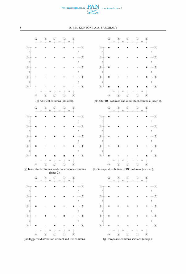
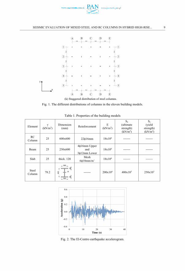
Figure 1 shows the different distributions of RC and steel columns in the eleven different building
models, where the beams and slabs are of the RC type for all models. Figure 1(a) represents the
control model (consisting of RC square cross-section columns) against which every other model
will be compared. Figure 1(b) represents a model of RC columns inside and steel columns
distributed along the perimeter of the model. Figure 1(c) represents a model with all columns steel
except the center column which is RC. Figure 1(d) shows a model with x-shape in-plane
distribution of steel columns among the rest RC columns. Figure 1(e) shows a model with all steel
columns. Figure 1(f) represents a model with inner steel columns and with RC columns distributed
along the perimeter of the model. Figure 1(g) shows RC columns along the perimeter and the center
with steel columns distributed around the center of the model. Figure 1(h) represents a model with
an x-shape in-plane distribution of RC columns among the remaining steel columns. Figure 1(i)
shows a staggered distribution of both RC and steel columns. Figure 1(j) represents a model with
composite columns (steel B.F.I.B. columns encased in RC). Figure 1(k) shows a model with steel
B.F.I.B. columns with staggered webs directions (one in the x-direction and the other in the y-
direction) to avoid the effect of one direction web and not stiffen the model in one direction only
(the web’s direction).
Table 1 shows the properties of the members (SAP2000 elements) used in each building model.
6 D.-P.N. KONTONI, A.A. FARGHALY

The Egyptian Codes of Practice for loading (ECP-201) [16] for Reinforced Concrete (ECP-203)
[17] and for Steel Construction (ECP-205) [18] were adhered to.
A live load for a residential building of 2 kN/m2 is used, while the distributed load on the beams is
equal to 4.8 kN/m. The earthquake example applied here was the El-Centro earthquake with an
accelerogram as shown in Figure 2, with maximum ground acceleration equal to 0.322g and
exposure angle equal to 45o.
1
2
3
4
5
A B C D E
5.0 5.0 5.0 5.0
5.0
5.0
5.0
5.0
1
2
3
4
5
5.0
5.0
5.0
5.0
A B C D E5.0 5.0 5.0 5.0
1
2
3
4
5
A B C D E
5.0 5.0 5.0 5.0
5.0
5.0
5.0
5.0
1
2
3
4
5
5.0
5.0
5.0
5.0
A B C D E5.0 5.0 5.0 5.0
(a) All RC columns (all conc.). (b) Outer steel columns (outer 1).
1
2
3
4
5
A B C D E
5.0 5.0 5.0 5.0
5.0
5.0
5.0
5.0
1
2
3
4
5
5.0
5.0
5.0
5.0
A B C D E5.0 5.0 5.0 5.0
0.6
0.6
B.F.I.B.No.40
B.F.I.B.No.40
B.F.I.B.No.40
B.F.I.B.No.40
B.F.I.B.No.40
B.F.I.B.No.40
B.F.I.B.No.40
B.F.I.B.No.40
B.F.I.B.No.40
B.F.I.B.No.40
B.F.I.B.No.40
B.F.I.B.No.40
B.F.I.B.No.40
B.F.I.B.No.40
B.F.I.B.No.40
B.F.I.B.No.40
B.F.I.B.No.40
B.F.I.B.No.40
B.F.I.B.No.40
B.F.I.B.No.40
B.F.I.B.No.40
B.F.I.B.No.40
B.F.I.B.No.40
B.F.I.B.No.40 1
2
3
4
5
A B C D E
5.0 5.0 5.0 5.0
5.0
5.0
5.0
5.0
1
2
3
4
5
5.0
5.0
5.0
5.0
A B C D E5.0 5.0 5.0 5.0
(c) One center RC and outer steel columns (outer 2). (d) X-shape distribution of steel columns (x-steel).
SEISMIC EVALUATION OF MIXED STEEL AND RC COLUMNS IN HYBRID HIGH-RISE... 7
1
2
3
4
5
A B C D E
5.0 5.0 5.0 5.0
5.0
5.0
5.0
5.0
1
2
3
4
5
5.0
5.0
5.0
5.0
A B C D E5.0 5.0 5.0 5.0
1
2
3
4
5
A B C D E
5.0 5.0 5.0 5.0
5.0
5.0
5.0
5.0
1
2
3
4
5
5.0
5.0
5.0
5.0
A B C D E5.0 5.0 5.0 5.0
(e) All steel columns (all steel). (f) Outer RC columns and inner steel columns (inner 1).
1
2
3
4
5
A B C D E
5.0 5.0 5.0 5.0
5.0
5.0
5.0
5.0
1
2
3
4
5
5.0
5.0
5.0
5.0
A B C D E5.0 5.0 5.0 5.0
1
2
3
4
5
A B C D E
5.0 5.0 5.0 5.0
5.0
5.0
5.0
5.0
1
2
3
4
5
5.0
5.0
5.0
5.0
A B C D E5.0 5.0 5.0 5.0
(g) Inner steel columns, and core concrete columns (inner 2).
(h) X-shape distribution of RC columns (x-conc.).
1
2
3
4
5
A B C D E
5.0 5.0 5.0 5.0
5.0
5.0
5.0
5.0
1
2
3
4
5
5.0
5.0
5.0
5.0
A B C D E5.0 5.0 5.0 5.0
1
2
3
4
5
A B C D E
5.0 5.0 5.0 5.0
5.0
5.0
5.0
5.0
1
2
3
4
5
5.0
5.0
5.0
5.0
A B C D E5.0 5.0 5.0 5.0
(i) Staggered distribution of steel and RC columns. (j) Composite columns sections (comp.).
8 D.-P.N. KONTONI, A.A. FARGHALY
1
2
3
4
5
A B C D E
5.0 5.0 5.0 5.0
5.0
5.0
5.0
5.0
1
2
3
4
5
5.0
5.0
5.0
5.0
A B C D E5.0 5.0 5.0 5.0
(k) Staggered distribution of steel columns.
Fig. 1. The different distributions of columns in the eleven building models.
Table 1. Properties of the building models
Element γ(kN/m3)
Dimension (mm) Reinforcement E
(kN/m2)
Su(ultimate strength) (kN/m2)
Sy(yield
strength) (kN/m2)
RCColumn 25 600x600 22�16mm 18x106 ------- -------
Beam 25 250x6004�16mm Upper
and 3�12mm Lower
18x106 ------- -------
Slab 25 thick. 120 Mesh 6�10mm/m’ 18x106 ------- -------
SteelColumn 78.2
300
26
14
400
300
26
------- 200x106 400x103 250x103
Fig. 2. The El-Centro earthquake accelerogram.
x
y
-0.4
-0.2
0.0
0.2
0.4
0.6
0 10 20 30 40
Acc
eler
atio
n (g
)
Time (s)
SEISMIC EVALUATION OF MIXED STEEL AND RC COLUMNS IN HYBRID HIGH-RISE... 9

3. RESULTS AND DISCUSSION
In total, the eleven 12-storey 3D building models (with each floor measuring 3m in height) present
in Figure 1 were analyzed via SAP2000 to show the efficiency of dual hybrid structural systems
composed of reinforced concrete beams and slabs, as well as reinforced concrete and steel columns.
Top displacements and accelerations, base normal forces, base shear forces, and base bending
moments were computed to evaluate the chosen structural systems, and the time history maximum
values are presented herein.
Figure 3 shows the top lateral displacements in the x- and y- directions for different distributions of
columns across the various models. The lateral top displacements in the x-direction have larger
values in the cases of: “all RC” columns, the “outer 1”, the x-shape distributed steel columns
(among RC ones), the composite columns, and the staggered mixed columns, all due to the heavier
weight of all these models, while the rest of the cases are nearly equal, except for the case of the
staggered steel column model, where the lowest displacement was recorded because of the high
stiffness of the model due to the staggered webs of B.F.I.B. in both directions and the lower weight
of the model.
The lateral top displacements in the y-direction have maximum values in the cases of: all RC
columns, the “outer 2”, all steel columns (unidirectional webs: all webs are in the x-direction, and
the y-direction is the weak web axis), and the composite columns. The smaller values of the lateral
y-direction displacements are seen in cases “outer 1”, “inner 1”, and “inner 2”, because the webs of
steel columns are in the x-direction and the number of steel columns is higher than that of the RC
columns. The lateral top displacements in the y-direction for the x-shape distributed steel or x-shape
distributed RC column cases are nearly equal, indicating the effect of the mixed system between RC
and steel columns in both distribution and their overall number. Finally, the top displacements in
the y-direction for staggered mixed (steel and RC) columns and staggered steel columns are nearly
equal, which means that the effect of stiffening the model with steel and RC columns is equal in the
y-direction since the steel columns are directed in such a way as to give a similar effect in the y-
direction as that of the RC columns in the model.
10 D.-P.N. KONTONI, A.A. FARGHALY

Fig. 3. Top lateral displacements in the x- and y-directions for different distributions of columns.
Figure 4 represents the top accelerations in the x- and y-directions for different distributions of the
columns in the building models. The top y-acceleration is less than the top x-acceleration for all
models except for composite and “all RC” columns models. The high values of acceleration
demonstrate the high stiffness of the model. The stiffness is higher in composite section columns
than in all RC columns in both the x- and y-directions. The x-direction acceleration shows similar
values for almost all models, while in the steel staggered column model the lowest value (reduced
by almost 1.2 times when comparing to the rest of the models) was recorded. For y-direction
acceleration, the “outer 2” and “all steel” cases show similar behavior, the “outer 1”, “inner 1”,
“inner 2”, and staggered models show similar behavior, and both the x-shape distributed steel and
RC columns show roughly similar behavior.
SEISMIC EVALUATION OF MIXED STEEL AND RC COLUMNS IN HYBRID HIGH-RISE... 11

Fig. 4. Top accelerations in the x- and y-directions for different distributions of columns.
Figure 5 shows the base normal forces for different distributions of the columns across the building
models. The greatest value of normal force is seen in the case of the composite column model
(where the columns carry 1.15 more than the RC columns), and the lowest value of normal force is
in the staggered steel case (1.13 lower than the RC column cases). The “outer 2” and “all steel”
model cases are 1.06 times lower than the RC column model.
Figure 6 represents the base shear forces in the x- and y-directions for models with different
distributions of the columns in the building models. The base shear forces in the y-direction are
lower than the corresponding values in the x-direction (since the strong axes of the B.F.I.B. web
steel sections are in the x-direction), the higher values of the base shear force are seen in the cases
of “all RC” and composite columns; most base shear force values in the y-direction are close, but in
the case of “all steel” columns, the base shear force shows the lowest value, and, in most cases, the
ratios between the base shear and the “all RC” and composite column cases equal nearly 1.6 and
1.8, respectively. The base shear in the x-direction is larger than in the y-direction for different the
distributions of columns, though most cases show comparable values, except in the “all RC” and
composite column cases, where the ratios between the mean values of the base shear force in the x-
direction and the “all RC” and composite columns are nearly 1.13 and 1.3, respectively. The “all
12 D.-P.N. KONTONI, A.A. FARGHALY

RC” and “composite” column cases represent the highest values of base shear forces in both the x-
and y-directions.
Figure 7 represents the base bending moments in the x- and y-directions for models with different
distributions of the columns. Bending moment Mx is less than My for all cases of columns
distributions. The bending moments in the x-direction for “outer 2” and “all steel” cases record the
lower values (the low ability of these configuration cases to resist earthquake loads), while for “all
RC” and “composite” cases the bending moments record higher values. The bending moments in
the y-direction for all distribution patterns are rather close, except for the “all RC” and “composite”
column cases, where the ratios between most cases and the “all RC” and “composite” cases are
equal to almost 1.1 and 1.5, respectively.
Fig. 5. Base normal forces for different distributions of columns.
SEISMIC EVALUATION OF MIXED STEEL AND RC COLUMNS IN HYBRID HIGH-RISE... 13

Fig. 6. Base shear forces in the x- and y-directions for different distributions of columns.
Fig. 7. Base bending moments in the x- and y-directions for different distributions of columns.
14 D.-P.N. KONTONI, A.A. FARGHALY

4. CONCLUSIONS
The development of high-rise building construction has increased the need for structural design
solutions in which hybrid steel and reinforced concrete distributions are used. In this paper, various
arrangements of reinforced concrete columns and steel columns were used to form hybrid structural
systems combining their distinct advantages.
Three-dimensional high-rise building models consisting of reinforced concrete slabs and beams, and
having various mixed steel and reinforced concrete column distributions were subjected to
earthquake excitation and then analyzed via the SAP2000 software in order to investigate the most
suitable arrangement of mixed steel and reinforced concrete columns. Eleven 3D building models
with RC beams and slabs with various column distribution patterns (hybrid systems of mixed RC
and steel columns with different arrangements) were investigated to study the seismic performance
of these models.
In order to properly judge these hybrid systems, the models were subjected to an earthquake and the
top lateral displacements, top lateral accelerations, base normal forces, base shear forces, and base
bending moments were computed, and comparisons were made between the control case (all RC
columns) and the different configuration cases of mixed RC and steel columns. The following
conclusions can be drawn:
� Differential and irregular vertical displacements in the same plane in the case of RC with
steel columns at the same floor level (related to different column material response under
seismic load) may cause a redistribution of forces in the structural components.
� RC columns provide more of the damping effect than steel ones.
� Vaccination of a reinforced concrete column system with steel columns is useful in raising
the efficiency of seismic resistance of reinforced concrete structures.
� The effect of the light weight of steel columns used in building models helps to reduce the
seismic response of hybrid RC buildings.
� A hybrid system of mixed RC and steel columns is helpful in supporting structures found in
seismic zones.
� RC and composite section columns give the maximum base shear forces and base bending
moments.
� Steel columns give the minimum base shear forces and base bending moments.
SEISMIC EVALUATION OF MIXED STEEL AND RC COLUMNS IN HYBRID HIGH-RISE... 15

REFERENCES
1. A. S. Elnashai, B. M. Broderick, “Seismic Resistance of Composite Beam-Columns in Multi-Storey Structures”, Part 1: Experimental Studies. Journal of Constructional Steel Research 30(3): 201-229, 1994. DOI: https://doi.org/10.1016/0143-974X(94)90001-9.
2. N. E. Shanmugam, B. Lakshmi, “State of the art report on steel-concrete composite columns”, Journal of Constructional Steel Research 57(10): 1041–1080, 2001. DOI: https://doi.org/10.1016/S0143-974X(01)00021-9.
3. C.-M. Chan, “Optimal lateral stiffness design of tall buildings of mixed steel and concrete construction”, The Structural Design of Tall and Special Buildings, 10(3): 155–177, 2001. DOI: https://doi.org/10.1002/tal.170.
4. M. A. Hadianfard, A. Farahani, A. B-Jahromi, “On the effect of steel columns cross sectional properties on the behaviours when subjected to blast loading”, Structural Engineering and Mechanics 44(4): 449-463, 2012. DOI: https://doi.org/10.12989/sem.2012.44.4.449.
5. H. Esmaeili, A. Kheyroddin, M. A. Kafi, H. Nikbakht, “Comparison of nonlinear behavior of steel moment frames accompanied with RC shear walls or steel bracings”, The Structural Design of Tall and Special Buildings 22(14): 1062–1074, 2013. DOI: https://doi.org/10.1002/tal.751.
6. P. Z. Cao, Y. F. Lu, K. Wu, “Experimental research on sagging bending resistance of steel sheeting-styrofoam-concrete composite sandwich slabs”, Steel and Composite Structures 15(4): 425-438, 2013. DOI: http://dx.doi.org/10.12989/scs.2013.15.4.425.
7. A.K. Kvedaras, G. Sauciuvenas, A. Komka, E. Jarmolajeva “Analysis of behaviour for hollow/solid concrete-filled CHS steel beams”, Steel and Composite Structures 19(2): 293–308, 2015. DOI: https://doi.org/10.12989/scs.2015.19.2.293.
8. C. Xiao, F. Deng, T. Chen, Z. Zhao, “Experimental study on concrete-encased composite columns with separate steel sections”, Steel and Composite Structures 23(4): 483-491, 2017. DOI: https://doi.org/10.12989/scs.2017.23.4.483.
9. A. H. A. Buyuktaskin, “A study on the comparison of a steel building with braced frames and with RC walls”, Earthquakes and Structures 12(3): 263-270, 2017. DOI: https://doi.org/10.12989/eas.2017.12.3.263.
10. D. V. Bompa, A. Y. Elghazouli, “Force Transfer Mechanisms between Steel Columns and RC Beams by means of Shearkeys”, Proceedings of Eurosteel 2014: 7th European conference on steel composite structures, Naples, Italy, 10-12 September, Paper No. 03-476, pp. 1-6, 2014.
11. D. V. Bompa, A. Y. Elghazouli, “Ultimate shear behaviour of hybrid reinforced concrete beam-to-steel column assemblages”, Engineering Structures 101: 318–336, 2015. DOI: http://dx.doi.org/10.1016/j.engstruct.2015.07.033.
12. D. V. Bompa, A. Y. Elghazouli, “Structural performance of RC flat slabs connected to steel columns with shear heads”, Engineering Structures 117: 161–183, 2016. DOI: https://doi.org/10.1016/j.engstruct.2016.03.022.
13. M. I. Moharram, D. V. Bompa, A. Y. Elghazouli, “Experimental and Numerical Assessment of Mixed RC Beam and Steel Column Systems”, Journal of Constructional Steel Research 131: 51–67, 2017. DOI: https://doi.org/10.1016/j.jcsr.2016.12.019.
14. M. Moharram, D. Bompa, and A. Elghazouli, “Inelastic Assessment of Hybrid RC Beams to Steel Column Configurations Using Structural Steel Shear-Keys”, In: Hordijk D., Luković M. (eds), High Tech Concrete: Where Technology and Engineering Meet (Proceedings of the 2017 fib Symposium, held in Maastricht, The Netherlands, June 12-14, 2017), Springer, Cham, pp. 1336-1343, 2018. DOI: https://doi.org/10.1007/978-3-319-59471-2_154.
15. SAP2000® Version 17. Integrated Software for Structural Analysis and Design; Computers and Structures, Inc.: Walnut Creek, CA, USA; New York, NY, USA, 2015.
16. ECP-201. Egyptian Code of Practice for Calculating Loads and Forces in Structural Work and Masonry, ECP-201. Housing and Building National Research Center, Ministry of Housing, Utilities and Urban Planning, Cairo, Egypt, 2008.
17. ECP-203. Egyptian Code of Practice for Design and Construction of Reinforced Concrete Structures, ECPCS-203. Housing and Building National Research Center, Ministry of Housing, Utilities and Urban Planning, Cairo, Egypt, 2007.
18. ECP-205. Egyptian Code of Practice for steel construction, Load and Resistance Factor Design (LRFD), ECP-205. Housing and Building National Research Center, Ministry of Housing, Utilities and Urban Planning, Cairo, Egypt, 2008.
16 D.-P.N. KONTONI, A.A. FARGHALY

LIST OF FIGURES AND TABLES:
Fig. 1. The different distributions of columns in the eleven building models.
Fig. 2. The El-Centro earthquake accelerogram.
Fig. 3. Top lateral displacements in the x- and y-directions for different distributions of columns.
Fig. 4. Top accelerations in the x- and y-directions for different distributions of columns.
Fig. 5. Base normal forces for different distributions of columns.
Fig. 6. Base shear forces in the x- and y-directions for different distributions of columns.
Fig. 7. Base bending moments in the x- and y-directions for different distributions of columns.
Table 1. Properties of the building models.
Received 05.12.2018
Revised 30.06.2019
SEISMIC EVALUATION OF MIXED STEEL AND RC COLUMNS IN HYBRID HIGH-RISE... 17


![ExperimentalInvestigationonSeismicBehavioursofReinforced ... · 2019. 12. 29. · seismic loading tests of eight full-size corroded RC short columns,VuandLi[19] ... load-bearing and](https://static.fdocuments.us/doc/165x107/60a8b5614824376307010f0c/experimentalinvestigationonseismicbehavioursofreinforced-2019-12-29-seismic.jpg)


