SEISMIC DESIGN CODE FOR DUBAI
106
..:: ....... ..... -.I--t ...... " ... .. U," SEISMIC DESIGN CODE FOR DUBAI Du ba l MUni cipality I 2013 I
Transcript of SEISMIC DESIGN CODE FOR DUBAI

..::....... ..... -.I--t
...... " ... ".,~ .. U,"
SEISMIC DESIGN CODE FOR DUBAI
Dubal MUnicipality
I 2013 I

i
SEISMIC AALYSIS AD DESIG REQUIREMETS
FOR BUILDIGS
1. GEERAL REQUIREMETS 1
1.1. SCOPE, NOTATIONS, REFERENCE STANDARDS 1
1.1.1. Scope 1
1.1.2. Notations 1
1.1.3. Reference standards 6
1.2. SEISMIC GROUND MOTION 7
1.2.1. Earthquake levels 7
1.2.2. Representation of ground motion: Elastic Response Spectrum 7
1.2.3. Representation of ground motion in time domain 8
1.3. SEISMIC PERFORMANCE OBJECTIVES 10
1.3.1. Classification of buildings 10
1.3.2. Performance levels and ranges 10
1.3.3. Minimum performance objective for low- to medium-rise buildings 11
1.3.4. Multiple minimum performance objectives for tall buildings 11 1.4. GENERAL GUIDELINES FOR ARRANGEMENT OF BUILDING STRUCTURAL SYSTEMS 13 1.4.1. Structural simplicity 13 1.4.2. Uniformity, symmetry and redundancy 13 1.4.3. Adequate resistance and stiffness 13 1.4.4. Diaphragm action 14 1.4.5. Adequate foundation 14
1.5. REGULARITY REQUIREMENTS 15
1.5.1. Definition of Irregular Buildings 15
1.5.2. Conditions for Irregular Buildings 15
1.6. PRIMARY AND SECONDARY SEISMIC MEMBERS 17
1.6.1. Primary members 17
1.6.2. Secondary members 17
2. SEISMIC AALYSIS REQUIREMETS OF BUILDIGS 18
2.1. PARAMETERS OF DESIGN RESPONSE SPECTRUM 18
2.1.1. Importance Factors 18
2.1.2. Seismic Load Reduction Factors 18
2.1.3. Design Response Spectrum 19
2.2. SEISMIC ANALYSIS 20
2.2.1. Applicable analysis methods 20
2.2.2. Selection of analysis method for low- to medium-rise buildings 20
2.2.3. Definition of seismic mass 20
2.2.4. Consideration of vertical component of earthquake 21
2.3. EQUIVALENT SEISMIC LOAD METHOD 22
2.3.1. Displacement components and application points of seismic loads 22
2.3.2. Base shear 22
2.3.3. Storey seismic loads 22
2.3.4. Predominant period 23
2.3.5. Directional combination 24
2.4. MULTI-MODE RESPONSE SPECTRUM ANALYSIS METHOD 25
2.4.1. Dynamic degrees of freedom 25
2.4.2. Modal seismic loads 25
2.4.3. Number of vibration modes 26
ii
2.4.4. Modal combination 26
2.4.5. Scaling of response quantities 26
2.4.6. Directional combination 27
2.5. RESPONSE HISTORY ANALYSIS METHOD 28
2.5.1. Linear Response History Analysis 28
2.5.2. Nonlinear Response History Analysis 28
2.6. SAFETY VERIFICATION 29
2.6.1. Strength verification 29
2.6.2. Load combinations for seismic design 29
2.6.3. Second-order effects 29
2.7. DAMAGE LIMITATION 31
2.7.1. Limitation of story drifts 31
2.7.2. Seismic joints 31
2.8. ANALYSIS REQUIREMENTS FOR NONSTRUCTURAL SYSTEMS 33
3. SEISMIC DESIG REQUIREMETS FOR REIFORCED COCRETE
BUILDIGS 34
3.1. SCOPE AND DESIGN CONCEPTS 34
3.1.1. Scope 24
3.1.2. Design Concepts 34
3.1.3. Structural types and Behaviour Factors 34
3.1.4. Design actions 35
3.1.5. Capacity Design Rules 36
3.1.6. Material requirements 37
3.1.7. Local ductility requirements 37
3.2. SEISMIC DESIGN REQUIREMENTS FOR REINFORCED CONCRETE
BEAMS 38
3.2.1. Geometrical requirements 38
3.2.2. Design shear forces of beams 38
3.2.3. Seismic detailing of beams 39
3.3. SEISMIC DESIGN REQUIREMENTS FOR REINFORCED CONCRETE
COLUMNS 40
3.3.1. Geometrical requirements 40
3.3.2. Design shear forces of columns 40
3.3.3. Seismic detailing of columns 40
3.3.4. Seismic detailing of beam-column joints 41
3.4. SEISMIC DESIGN REQUIREMENTS FOR REINFORCED CONCRETE
STRUCTURAL WALLS 43
3.4.1. Geometrical requirements 43
3.4.2. Design bending moments and shear forces of structural walls 43
3.4.3. Seismic detailing of structural walls 44
3.5. REQUIREMENTS FOR ANCHORAGE AND SPLICING OF REBARS 45
3.5.1. General 45
3.5.2. Anchorage of rebars 45
3.5.3. Splicing of rebars 46
3.6. DESIGN AND DETAILING OF SECONDARY SEISMIC ELEMENTS
3.7. SEISMIC DESIGN REQUIREMENTS FOR FOUNDATIONS 48
3.7.1. General 48
3.7.2. Tie-beams and foundation beams 48
3.7.3. Connection of vertical elements with foundation beams and walls 48
3.7.4. Cast-in-place concrete piles and pile caps 49
iii
4. SEISMIC DESIG REQUIREMETS FOR STRUCTURAL STEEL
BUILDIGS 50
4.1. SCOPE AND DESIGN CONCEPTS 50
4.1.1. Scope 50
4.1.2. Design Concepts 50
4.1.3. Structural types and Behaviour Factors 50
4.1.4. Material requirements 51
4.2. GENERAL DESIGN CRITERIA AND DETAILING RULES 53
4.2.1. Design rules for ductile elements in compression or bending 53
4.2.2. Design rules for ductile elements in tension 53
4.2.3. Design rules for connections 53
4.3. DESIGN AND DETAILING RULES FOR MOMENT RESISTING FRAMES 54
4.3.1. Design criteria 54
4.3.2. Beams 54
4.3.3. Columns 55
4.3.4. Beam-column connections 56
4.4. DESIGN AND DETAILING RULES FOR FRAMES WITH CONCENTRIC
BRACINGS 57
4.4.1. Design criteria 57
4.4.2. Analysis 57
4.4.3. Diagonal members 57
4.4.4. Beams and columns 58
4.5. DESIGN AND DETAILING RULES FOR FRAMES WITH ECCENTRIC
BRACINGS 60
4.5.1. Design criteria 60
4.5.2. Seismic links 60
4.5.3. Members not containing seismic links 62
4.5.4. Connections of seismic links 63
4.6. DESIGN RULES FOR STEEL BUILDINGS WITH CONCRETE CORES OR
CONCRETE WALLS 64
4.7. DESIGN RULES FOR INVERTED PENDULUM STRUCTURES 65
5. SEISMIC DESIG REQUIREMETS FOR STEEL – COCRETE
COMPOSITE BUILDIGS 66
5.1. SCOPE AND DESIGN CONCEPTS 66
5.1.1. Scope 66
5.1.2. Design concepts 66
5.1.3. Structural types and Behaviour Factors 67
5.1.4. Material requirements 68
5.2. STRUCTURAL ANALYSIS 70
5.2.1. Scope 70
5.2.2. Stiffness of sections 70
5.3. DESIGN CRITERIA AND DETAILING RULES FOR DISSIPATIVE
STRUCTURAL BEHAVIOUR COMMON TO ALL STRUCTURAL TYPES 71
5.3.1. Design criteria for dissipative structures 71
5.3.2. Plastic resistance of dissipative zones 71
5.3.3. Detailing rules for composite connections in dissipative zones 71
5.4. RULES FOR MEMBERS 73
5.4.1. General 73
5.4.2. Steel beams composite with slab 74
5.4.3. Effective width of slab 75
iv
5.4.4. Fully encased composite columns 76
5.4.5. Partially-encased members 77
5.4.6. Filled composite columns 78
5.5. DESIGN AND DETAILING RULES FOR MOMENT FRAMES 79
5.5.1. Specific criteria 79
5.5.2. Analysis 79
5.5.3. Rules for beams and columns 79
5.5.4. Beam to column connections 80
5.5.5. Condition for disregarding the composite character of beams with slab 80
5.6. DESIGN AND DETAILING RULES FOR COMPOSITE
CONCENTRICALLY BRACED FRAMES 81
5.6.1. Specific criteria 81
5.6.2. Analysis 81
5.6.3. Diagonal members 81
5.6.4. Beams and columns 81
5.7. DESIGN AND DETAILING RULES FOR COMPOSITE
ECCENTRICALLY BRACED FRAMES 82
5.7.1. Specific criteria 82
5.7.2. Analysis 82
5.7.3. Seismic links 82
5.7.4. Members not containing seismic links 83
5.8. DESIGN AND DETAILING RULES FOR STRUCTURAL SYSTEMS
MADE OF REINFORCED CONCRETE STRUCTURAL WALLS
COMPOSITE WITH STRUCTURAL STEEL ELEMENTS 84
5.8.1. Specific criteria 84
5.8.2. Analysis 84
5.8.3. Detailing rules for composite walls 84
5.8.4. Detailing rules for coupling beams 85
5.9. DESIGN AND DETAILING RULES FOR COMPOSITE
STRUCTURAL WALLS 86
5.9.1. Specific criteria 86
5.9.2. Analysis 86
5.9.3. Detailing rules 86
6. PERFORMACE-BASED SEISMIC DESIG REQUIREMETS FOR
TALL BUILDIGS 87
6.1. SEISMIC ANALYSIS PROCEDURES FOR TALL BUILDINGS 87
6.2. REQUIREMENTS FOR ANALYSIS MODELING 88
6.3. PERFORMANCE-BASED SEISMIC DESIGN STAGES OF TALL
BUILDINGS 90
6.3.1. Design Stage (I – A): Preliminary Design (dimensioning) with Linear
Analysis for Controlled Damage/Life Safety Performance Objective
under (E2) Level Earthquake 90
6.3.2. Design Stage (I – B): Design with Nonlinear Analysis for Life Safety /
Controlled Damage Performance Objective under (E2) Level
Earthquake 90
6.3.3. Design Stage (II): Design Verification with Linear Analysis for Minimum
Damage/Immediate Occupancy Performance Objective under (E1) Level
Earthquake
91
v
6.3.4. Design Stage (III): Design Verification with Nonlinear Analysis for
Extensive Damage/ Collapse Prevention Performance Objective under
(E3) Level Earthquake 91
6.4. DESIGN REQUIREMENTS FOR NONSTRUCTURAL ARCHITECTURAL
AND MECHANICAL/ELECTRICAL ELEMENTS/COMPONENTS 93
6.4.1. General requirements 93
6.4.2. Equivalent seismic loads 93
6.4.3. Limitation of displacements 96
6.4.4. Nonstructural façade elements and connections 96
6.5. INDEPENDENT DESIGN REVIEW 96
7. STRUCTURAL HEALTH MOITORIG SYSTEMS FOR
TALL BUILDIGS 97
AEX A. SOIL CLASSIFICATIO FOR SPECIFICATIO OF SEISMIC
GROUD MOTIO 98
A.1. Soil classification procedure 98
A.2. Steps for classifying Soil Classes C,D,E,F 99
A.3. Classifying Soil Classes A,B 100
1
CHAPTER 1
GEERAL REQUIREMETS
1.1. SCOPE, OTATIOS, REFERECE STADARDS
1.1.1. Scope
1.1.1.1 – This standard covers the seismic analysis and design requirements of reinforced
concrete and steel building structures to be constructed within boundaries of Emirate of
Dubai.
1.1.1.2 – This standard is applicable to low- to medium rise buildings as well as to tall
buildings, as defined in 1.3.1.
(a) All parts of this standard excluding Chapters 6 and 7 are applicable to low- to medium
rise buildings.
(b) Special seismic analysis and design requirements applicable to tall buildings are given in
Chapters 6 and 7. Parts of sections 1.2 and 1.3 of Chapter 1 as well as parts of Chapter 2
that are referred to in Chapter 6 are also applicable to tall buildings.
1.1.1.3 – Civil engineering structures other than buildings are outside the scope of this code.
1.1.1.4 – Base-isolated buildings as well as buildings equipped with active or passive control
systems and devices are outside the scope of this code.
1.1.2. otations
A = Gross area of seismic link
Ac = Total effective area of structural walls in the first storey for empirical calculation of
predominant period in the eartquake direction [m2]
Ae = Maximum acceleration acting on nonstructural element or component
Aj = Effective area of the j’th structural walls in the first storey for empirical calculation
of predominant period in the eartquake direction [m2]
Apl = Horizontal area of the plate
Ast = Area of one leg of the transverse reinforcement; area of stiffener
Be = Amplification factor for nonstructural element or component
b = Width of the flange
bb = Width of composite beam or bearing width of the concrete of the slab on the
column
bc = Cross sectional dimension of column
be = Partial effective width of flange on each side of the steel web
beff = Effective flange width of beam in tension at the face of a supporting column; total
effective width of concrete flange
bi = Distance between consecutive bars engaged by a corner of a tie or a cross-tie in a
column
bo = Width of a confined core in a column or in the boundary element of a wall (to
centerline of hoops)
bw = Width of the web of a beam
bwo = Web thickness of wall
Ct = Empirical factor for the calculation of predominant period in the earthquake

2
direction
Di = Torsion amplification factor at i’th storey
Do = Diameter of confined core in a circular column
d = Effective depth of section
dbL = Longitudinal bar diameter
dbw = Diameter of hoop
dfi = Fictitious displacements at i’th storey used in Rayleigh quotient
dji = Reduced storey displacement of the j’th vertical element at i’th storey
Ea = Modulus of Elasticity of steel
Ecm = Mean value of Modulus of Elasticity of concrete in accordance with EN 1992-1-
1:2004
Ed = Design value of an action effect
Edi = Design value of the action effect on the zone or element i in the seismic design
situation
EE = Action effect due to seismic load
EFd = Design value of an action effect on the foundation
EG = Action effect due to dead load
EF,E = Action effect from the analysis of the design seismic action
EF,G = Action effect due to the non-seismic actions included in the combination of
actions for the seismic design situation
EQ = Action effect due to live load
e = Length of seismic link
Ffi = Fictitious forces at i’th storey used in Rayleigh quotient
Fi = Equivalent seismic load acting at i’th storey
Fxin = Modal seismic load in the n’th mode acting at i’th storey in x direction
Fyin = Modal seismic load in the n’th mode acting at i’th storey in y direction
Fθin = Modal seismic torque in the n’th mode acting at i’th storey around the vertical axis
passing through mass centre
fcd = Design value of concrete compressive strength
fce = Exopected value of concrete compressive strength
fck = Characteristic value of concrete compressive strength
fctm = Mean value of concrete tensile strength
fy = Nominal value of steel yield strength
fyd = Design value of steel yield strength
fye = Expected value of steel yield strength
fydf = Design yield strength of steel in the flange
fyd,v = Design value of yield strength of the vertical web reinforcement
fydw = Design strength of web reinforcement
fyk = Characteristic value of steel yield strength
fyld = Design value of yield strength of longitudinal reinforcement
fywd = Design value of yield strength of transverse reinforcement
fe = Equivalent seismic load acting at the mass centre of nonstructural element
Gi = Total dead load at i’th storey of building
g = Acceleration of gravity (9.81 m/s2)
Hi = Total height of building measured from the top foundation level
(In buildings with rigid peripheral basement walls, total height of building
measured from the top of the ground floor level) [m]
HN = Total height of building measured from the top foundation level
(In buildings with rigid peripheral basement walls, total height of building
measured from the top of the ground floor level) [m]

3
Hw = Total wall height measured from top foundation level or ground floor level h = Cross sectional depth
hb = Depth of composite beam
hc = Cross sectional depth of a column in a given direction
hf = Flange depth
hi = Height of i’th storey of building [m]
ho = Depth of confined core in a column (to centerline of hoops)
hw = Depth of beam
I = Building Importance Factor
Ia = Second moment of area of the steel section part of a composite section, with
respect to the centroid of the composite section
Ic = Second moment of area of the concrete part of a composite section, with respect to
the centroid of the composite section Ieq equivalent second moment of area of the
composite section
Ie = Element (nonstructural) Importance Factor
Is = Second moment of area of the rebars in a composite section, with respect to the
centroid of the composite section
ke = Effective stiffness coefficient of the nonstructural element or component.
kr = Rib shape efficiency factor of profiled steel sheeting
kt = Reduction factor of design shear resistance of connectors in accordance with EN
1994-1-1:2004
L = Beam span
lc = Column height
lcl = Clear length of a beam or a column
lcr = Length of critical region
lw = Length of wall cross-section
lwj = Plan length of j’th structural wall or a piece of coupled wall at the first story
MEd = Design bending moment obtained from analysis for the seismic design situation
MEd,E = Bending moment due to design seismic action
MEd,G = Bending moment due to non-seismic actions in seismic design situation
MEd,W = Design bending moment obtained from analysis at the base of the wall for the
seismic design situation
Mi = i’th storey mass of building (Mi = Wi / g)
Mi,d = End moment of a beam or column for calculating capacity design shear
MN = Nominal plastic moment of RC section *nM = Modal mass of the n’th natural vibration mode
Mpl,Rd = Design value of plastic moment resistance
Mpl,Rd,A = Design value of plastic moment resistance at end A of a member
Mpl,Rd,B = Design value of plastic moment resistance at end B of a member
Mpl,Rd,c = Design value of plastic moment resistance of column, taken as lower bound and
computed taking into account the concrete component of the section and only the
steel components of the section classified as ductile
MRb,i = Design moment resistance of a beam at end i
MRc,i = Design moment resistance of a column at end i
MRd = Design bending moment resistance
MRd,W = Design bending moment resistance at the base of the wall
Mxn = Effective participating mass of the n’th natural vibration mode of building in
the x earthquake direction considered
Myn = Effective participating mass of the n’th natural vibration mode of building in
4
the y earthquake direction considered
Mt = Total mass of building (Mt = Wt / g)
MU,Rd,b = Upper bound plastic resistance of beam, computed taking into account the concrete
component of the section and all the steel components in the section, including
those not classified as ductile
MY = Bending moment corresponding to the state of first-yield in RC section
me = Nonstructural element mass
= Total number of stories of building from the foundation level
(In buildings with rigid peripheral basement walls, total number of stories from the
ground floor level)
Ed = Design axial force obtained from analysis for the seismic design situation
Ed,E = Axial force due to design seismic action
Ed,G = Axial force due to non-seismic actions in seismic design situation
pl,Rd = Design value of yield resistance in tension of the gross cross-section of a member in
accordance with EN 1993-1-1:2004
n = Steel-to-concrete modular ratio for short term actions
n1 = Live Load Mass Reduction Factor
n2 = Live Load Participation Factor
QCx = Response quantity obtained by modal combination in Response Spectrum
Method for an earthquake in x direction
QCy = Response quantity obtained by modal combination in Response Spectrum
Method for an earthquake in y direction
QD = Design response quantity due to seismic action
Qi = Total live load at i’th storey of building
QSx = Scaled response quantity obtained by modal combination in Response Spectrum
Method for an earthquake in x direction
QSy = Scaled response quantity obtained by modal combination in Response Spectrum
Method for an earthquake in y direction
Qx = Response quantity obtained in Equivalent Seismic Load Method for an earthquake
in x direction
Qy = Response quantity obtained in Equivalent Seismic Load Method for an earthquake
in y direction
q = Behaviour Factor
qe = Behaviour Factor for nonstructural element or component
qR(T) = Seismic Load Reduction Factor
Rd = Design resistance of an element; resistance of connection in accordance with EN
1993-1-1:2004
Rdi = Design resistance of the zone or element i
Rfy = Plastic resistance of connected dissipative member based on design yield strength
of material as defined in EN 1993-1-1:2004
SAE(T) = Elastic spectral acceleration [m /s2]
SAR(T) = Design (reduced) spectral acceleration [m /s2]
SSD = Short period (0.2 second) elastic spectral acceleration [m /s2]
S1D = 1.0 second elastic spectral acceleration [m /s2]
s = Spacing of transverse reinforcement [mm]
T = Natural period of vibration [s]
TL = Transition period of response spectrum to long-period range [s]
To = Response spectrum short corner period [s]
TS = Response spectrum long corner period [s]
T1 = Natural period of predominant mode (first mode) [s]

5
Tn = Natural period of n’th mode [s]
tf = Flange thickness of a seismic link
tw = Web thickness of a seismic link
Vb = Base shear in the earthquake direction considered
Vbx = Base shear in x earthquake direction
VbCx = Base shear obtained by modal combination in x earthquake direction
Vby = Base shear in x earthquake direction
VbCy = Base shear obtained by modal combination in y earthquake direction
VEd = Shear force obtained from analysis for the seismic design situation
V'Ed = Design shear force determined in accordance with capacity design rule
VEd,E = Shear force due to design seismic action
VEd,G = Shear force due to non-seismic actions in seismic design situation
VEd,M = Shear force due to application of plastic moment resistances at the two
ends
Vi = i’th storey seismic shear in the earthquake direction considered
Vic = Sum of seismic shear forces of all columns at the i’th storey in the earthquake
direction considered
Vis = Sum of seismic shear forces in the earthquake direction considered at the i’th storey
columns where strong column – weak beam condition is satisfied at both bottom
and top joints
Vpl,Rd = Design value of shear resistance of a member in accordance with EN 1993-1-1:
2004
Vwb,Rd = Shear buckling resistance of the web panel
Vwp,Ed = Design shear force in web panel due to design seismic action effects
Vwp,Rd = Shear resistance of the web panel in accordance with EN 1993- 1-8:2004, 6.2.4.1
Wi = Seismic weight of i’th storey of building
Wt = Total seismic weight of building corresponding to total mass, Mt
α = Confinement effectiveness factor; ratio of the smaller bending moments MEd,A at
one end of the link in the seismic design situation, to the greater bending moments
MEd,B at the end where the plastic hinge develops, both moments being taken as
absolute values.
αG = Coefficient used for determining the gap size of a seismic joint
αi = Ratio of Vis / Vic calculated for any i’th storey ∆ji = Reduced storey drift of the j’th vertical element at i’th storey
(∆i)avg = Average reduced storey drift of the i’th storey
δji = Effective storey drift of the j’th vertical element at i’th storey
(δi)max = Maximum effective storey drift of the i’th storey
∆FN = Additional equivalent seismic load acting on the N’th storey (top) of building
ε = Shear amplification factor of wall
εa = Total strain of steel at Ultimate Limit State
εcg = Upper limit (capacity) of concrete compressive strain in the extreme fiber inside the
confinement reinforcement
εcu2 = Ultimate compressive strain of unconfined concrete
εs = Upper limit (capacity) of strain in steel reinforcement
εsy,d = Design value of steel strain at yield
ηti = Torsional Irregularity Factor defined at i’th storey of building
ηci = Strength Irregularity Factor defined at i’th storey of building
ηki = Stiffness Irregularity Factor defined at i’th storey of building
Φxin = In buildings with floors modelled as rigid diaphragms, horizontal component
of n’th mode shape in the x direction at i’th storey of building

6
Φyin = In buildings with floors modelled as rigid diaphragms, horizontal component
of n’th mode shape in the y direction at i’th storey of building
Φθin = In buildings with floors modelled as rigid diaphragms, rotational component
of n’th mode shape around the vertical axis at i’th storey of building
ϕy = Yield curvature corresponding to nominal plastic moment
ϕ'y = Curvature corresponding to first-yield
Γxn = Participation Factor of n’th mode for x direction earthquake
γov = Material overstrength factor
γpb = Factor applied to design value pl,Rd of yield resistance in tension of the
compression brace in a V bracing
λ = Non-dimensional slenderness of a member as defined in EN 1993-1-1:2004
µϕ = Curvature ductility factor
dν = Axial force in seismic design situation, normalised to c cdA f
Ω = Value of (Rdi / Edi) ≤ q/I of the element i of the structure which has the highest
influence on the effect EF under consideration
ωw = Mechanical ratio of vertical web reinforcement (ωv = ρv fyd,v / fcd)
ωwd = Mechanical volumetric ratio of confining reinforcement
ρ = Tension reinforcement ratio
ρ' = Compression reinforcement ratio
ρmax = Maximum tension reinforcement ratio allowed in the critical region of a primary
beam
ρmin = Minimum tension reinforcement ratio to be provided along a beam
θi = Second Order Effect Indicator defined at i’th storey of building
θp = Rotation capacity of the plastic hinge region
RbM∑ = Sum of design values of moment resistances of beams framing in a joint in the
direction considered
RcM∑ = Sum of design values of moment resistances of columns framing in a joint in the
direction considered
1.1.3. Reference Standards
1.1.3.1 – The following standards are acceptable reference standards to be utilized in
combination with this standard:
EN 1990: Eurocode – Basis of structural design
EN 1992-1-1: Eurocode 2 – Design of concrete structures – Part 1-1: General - Common
rules for building and civil engineering structures
EN 1993-1-1: Eurocode 3 – Design of steel structures – Part 1-1: General - General rules
EN 1993-1-1: Eurocode 4 – Design of composite steel and concrete structures – Part 1-1:
General rules and rules for buildings
EN 1997-1: Eurocode 7 – Geotechnical design – Part 1: General rules
EN 1998-5: Eurocode 8 – Design of structures for earthquake resistance – Part 5:
Foundations, retaining structures and geotechnical aspects
1.1.3.2 – Regarding the utilization of the above-referenced Eurocodes, National Application
Documents of the United Kingdom may be applied.

7
1.2. SEISMIC GROUD MOTIO
1.2.1. Earthquake levels
The earthquake levels to be considered in this Code are defined in the following:
1.2.1.1 – (E1) Earthquake Level: This earthquake level represents relatively frequent but low-
intensity earthquake ground motions with a high probability to occur during the service life of
buildings within the scope of this Code. The probability of exceedance of (E1) level
earthquake in 50 years is 50%, which corresponds to a return period of 72 years.
1.2.1.2 – (E2) Earthquake Level: This earthquake level represents the infrequent and higher
intensity earthquake ground motions with a low probability to occur during the service life of
buildings within the scope of this Code. The probability of exceedance of (E2) level
earthquake in 50 years is 10%, which corresponds to a return period of 475 years.
1.2.1.3 – (E3) Earthquake Level: This earthquake level represents the highest intensity, very
infrequent earthquake ground motions that the buildings within the scope of this Code may be
subjected to. The probability of exceedance of (E3) level earthquake in 50 years is 2%, which
corresponds to a return period of 2475 years.
1.2.2. Representation of ground motion: Elastic Response Spectrum
1.2.2.1 – Within the boundaries of Emirate of Dubai, 5% damped horizontal elastic spectral
accelerations corresponding to short period (0.2 second), SSD , and 1.0 second natural
vibration period, S1D , are given for (E1), (E2) and (E3) earthquake levels in Table 1.1 for
local soil classes defined in Annex A.
1.2.2.2 – Elastic response spectrum representing the horizontal component of earthquake
ground motion is defined as follows (Fig.1.1):
SDAE SD o
o
AE SD o S
1DAE S L
1D LAE 2
( ) 0.4 0.6 ( )
( ) ( )
( ) ( )
( )
SS T S T T T
T
S T S T T T
SS T T T T
T
S TS T
T
= + ≤
= ≤ ≤
= ≤ ≤
= L( )T T≤
(1.1)
Spectrum corner periods To and TS are defined as:
1DS o S
SD
; 0.2S
T T TS
= = (1.2)
Transition period to long-period range shall be taken for Emirate of Dubai as TL = 8 s.

8
Table 1.1. Short period and 1.0 second elastic spectral accelerations
Earthquake Level
(E1) (E2) (E3) Soil
Class
SSD / g S1D / g SSD / g S1D / g SSD / g S1D / g
A 0.080 0.032 0.120 0.053 0.180 0.080
B 0.100 0.040 0.150 0.067 0.225 0.100
C 0.120 0.068 0.180 0.113 0.270 0.170
D 0.160 0.096 0.240 0.160 0.360 0.240
E 0.250 0.140 0.375 0.233 0.563 0.350
F Site-specific geotechnical investigation and dynamic site
response analysis required (see Annex A)
Figure 1.1. Elastic Response Spectrum
1.2.2.3 – When required, elastic acceleration spectrum may be determined through special
investigations by considering local seismic and site conditions. However 5% damped
acceleration spectrum ordinates shall in no case be less than those determined by Eq.(1.1)
based on short-period and 1.0 second spectral accelerations given in Table 1.1.
1.2.2.4 – Elastic response spectrum representing the vertical component of earthquake ground
motion may be taken as half the value of the corresponding to horizontal component.
1.2.3. Representation of ground motion in time domain
1.2.3.1 – A minimum three or seven sets of earthquake ground motions (acceleration records
in two perpendicular horizontal directions) with the following properties shall be selected for
the analysis to be performed in the time domain. Real acceleration records may be obtained
from the following data banks:
Cosmos Virtual Data Center http://db.cosmos-eq.org/
Peer Strong Motion Database http://peer.berkeley.edu/smcat/
To TS 1.0 TL T
0.4SSD
S1D
SAE
SSD
SAE = ____ S1D
T
SAE = ____ TL
T 2
S1D

9
European Strong- Motion Database http://www.isesd.cv.ic.ac.uk/ESD/frameset.htm
Japan K-NET NIED http://www.k-net.bosai.go.jp/
1.2.3.2 – In the cases where sufficient number of acceleration records cannot be found,
artificial earthquake ground motions generated as compatible with the earthquake simulations
or the elastic response spectrum may be used. The same acceleration record (accelerogram)
shall not be used for both directions. The ground motion simulations shall be based on a
physical model considering the fault mechanism, rupture characteristics and the geological
structure of the medium between the earthquake source and recording station.
1.2.3.3 – The average of 5% damped spectral amplitudes calculated at zero period from each
set of earthquake ground motion shall not be less than zero-period spectral amplitude of the
elastic response spectrum (0.4 SSD).
1.2.3.4 – The duration between the two points where acceleration amplitude first and last
exceed ±0.05g shall not be shorter than 5 times the dominant natural vibration period of the
building nor 15 seconds for each earthquake ground motion record.
1.2.3.5 – The resultant spectrum of an earthquake ground motion set shall be obtained through
square-root-of-sum-of-squares of 5% damped spectra of the two directions. The amplitudes of
earthquake ground motions shall be scaled according to a rule such that the average of
amplitudes of the resultant spectra of all records between the periods 0.2T and 1.2T
(T = Dominant natural vibration period of the building) shall not be less than 1.3 times the
amplitudes of the elastic response spectrum along the same period range. The scaling of both
components shall be made with the same factors.
1.2.3.6 – Regarding the seismic design of tall buildings according to Chapter 5, if needed,
parameters related to vertical component of the earthquake ground motion may be specified,
subject to the approval of the Independent Review Board where applicable.
10
1.3. SEISMIC PERFORMACE OBJECTIVES
1.3.1. Classification of buildings
For the purpose of identifying seismic performance objectives as well as analysis and design
requirements, buildings shall be classified into two groups, namely low- to medium-rise
buildings and tall buildings.
1.3.1.1 – Tall buildings are those of minimum 60 meter height measured from the lowest
ground level, excluding basement stories completely underground and surrounded with high-
stiffness peripheral walls all around.
1.3.1.2 – Buildings other than those described in 1.3.1.1 are defined as low- to medium-rise
buildings.
1.3.2. Performance levels and ranges
Performance levels of low- to medium-rise and/or tall buildings, whereever applicable, are
defined below with respect to estimated damage levels in earthquakes.
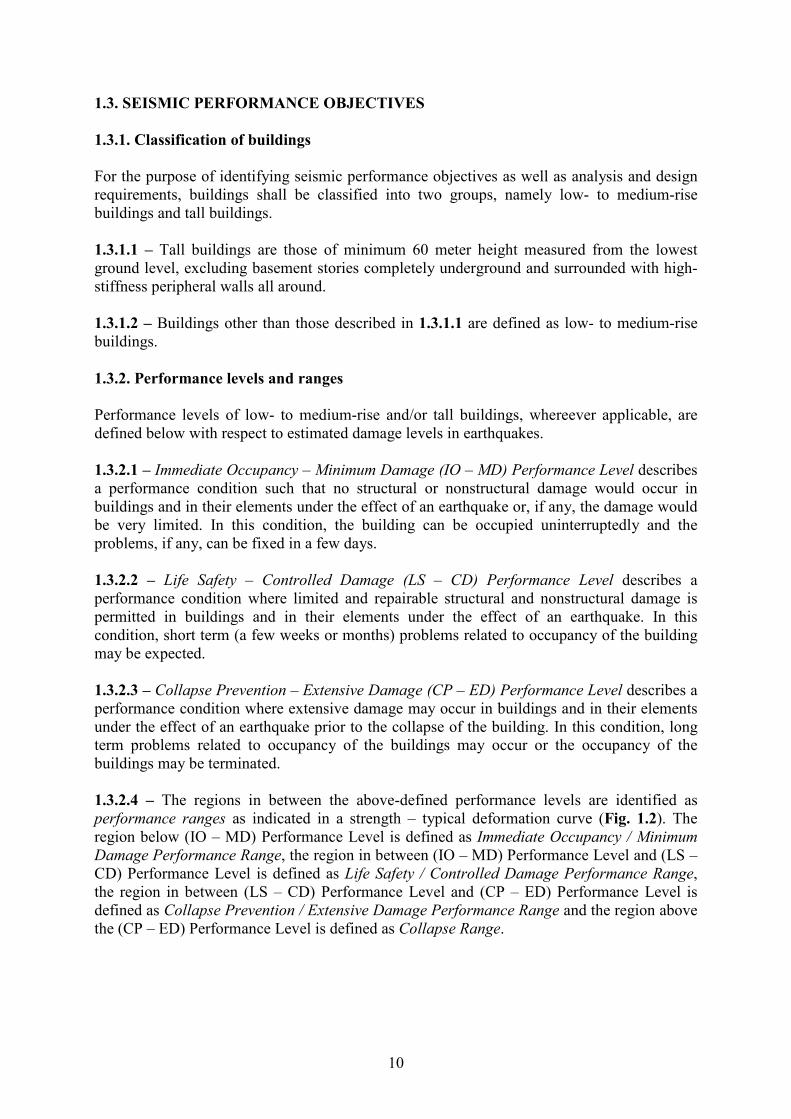
1.3.2.1 – Immediate Occupancy – Minimum Damage (IO – MD) Performance Level describes
a performance condition such that no structural or nonstructural damage would occur in
buildings and in their elements under the effect of an earthquake or, if any, the damage would
be very limited. In this condition, the building can be occupied uninterruptedly and the
problems, if any, can be fixed in a few days.
1.3.2.2 – Life Safety – Controlled Damage (LS – CD) Performance Level describes a
performance condition where limited and repairable structural and nonstructural damage is
permitted in buildings and in their elements under the effect of an earthquake. In this
condition, short term (a few weeks or months) problems related to occupancy of the building
may be expected.
1.3.2.3 – Collapse Prevention – Extensive Damage (CP – ED) Performance Level describes a
performance condition where extensive damage may occur in buildings and in their elements
under the effect of an earthquake prior to the collapse of the building. In this condition, long
term problems related to occupancy of the buildings may occur or the occupancy of the
buildings may be terminated.
1.3.2.4 – The regions in between the above-defined performance levels are identified as
performance ranges as indicated in a strength – typical deformation curve (Fig. 1.2). The
region below (IO – MD) Performance Level is defined as Immediate Occupancy / Minimum
Damage Performance Range, the region in between (IO – MD) Performance Level and (LS –
CD) Performance Level is defined as Life Safety / Controlled Damage Performance Range,
the region in between (LS – CD) Performance Level and (CP – ED) Performance Level is
defined as Collapse Prevention / Extensive Damage Performance Range and the region above
the (CP – ED) Performance Level is defined as Collapse Range.

11
Figure 1.2. Performance levels and ranges
1.3.3. Minimum performance objective for low- to medium-rise buildings
1.3.3.1 – Minimum performance objective for low- to medium-rise buildings with an
Importance Factor of I = 1.0 according to Table 2.1 is identified as Life Safety / Controlled
Damage Performance Objective under (E2) level earthquake specified in 1.2. Without any
analytical verification, it is implicitly assumed that a building designed to this performance
objective would automatically satisfy Immediate Occupancy /Minimum Damage Performance
Objective under (E1) level earthquake as well as Collapse Prevention / Extensive Damage
Performance Objective under (E3) level earthquake.
1.3.3.2 – Minimum performance objective for low- to medium-rise buildings with an
Importance Factor of I = 1.5 according to Table 2.1 is identified as Immediate Occupancy /
Minimum Damage Performance Objective under (E2) level earthquake specified in 1.2.
Without any analytical verification, it is implicitly assumed that a building designed to this
performance objective would automatically satisfy Life Safety / Controlled Damage
Performance Objective under (E3) earthquake level earthquake.
1.3.3.3 – Minimum performance objective for low- to medium-rise buildings with an
Importance Factor between I = 1.0 and I = 1.5 according to Table 2.1 is identified as in
between Immediate Occupancy / Minimum Damage Performance Objective and Life Safety /
Controlled Damage Performance Objective under (E2) level earthquake specified in 1.2.
1.3.3.4 – Upon the requirement of the Owner or the relevant State Authority, the above-given
minimum performance objectives for special low- to medium-rise buildings may be enhanced
by assigning higher importance factors within the limits of Table 2.1.
1.3.4. Multiple minimum performance objectives for tall buildings
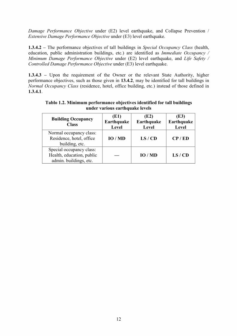
Minimum performance objectives identified for tall buildings are given below (Table 1.2)
depending upon the earthquake levels defined in 1.2:
1.3.4.1 – The multiple performance objectives of tall buildings in ormal Occupancy Class
(residence, hotel, office building, etc.) are identified as Immediate Occupancy / Minimum
Damage Performance Objective under (E1) level earthquake, Life Safety / Controlled
Immediate Occupancy/
Minimum Damage Performance
Range
Strength LS-CD CP-ED
Life Safety/
Controlled Damage Performance
Range
Collapse Prevention/ Ext. Damage Performance
Range Collapse Range
IO-MD
Typical
Deformation
12
Damage Performance Objective under (E2) level earthquake, and Collapse Prevention /
Extensive Damage Performance Objective under (E3) level earthquake.
1.3.4.2 – The performance objectives of tall buildings in Special Occupancy Class (health,
education, public administration buildings, etc.) are identified as Immediate Occupancy /
Minimum Damage Performance Objective under (E2) level earthquake, and Life Safety /
Controlled Damage Performance Objective under (E3) level earthquake.
1.3.4.3 – Upon the requirement of the Owner or the relevant State Authority, higher
performance objectives, such as those given in 13.4.2, may be identified for tall buildings in
ormal Occupancy Class (residence, hotel, office building, etc.) instead of those defined in
1.3.4.1.
Tablo 1.2. Minimum performance objectives identified for tall buildings
under various earthquake levels
Building Occupancy
Class
(E1)
Earthquake
Level
(E2)
Earthquake
Level
(E3)
Earthquake
Level
Normal occupancy class:
Residence, hotel, office
building, etc. IO / MD LS / CD CP / ED
Special occupancy class:
Health, education, public
admin. buildings, etc. –– IO / MD LS / CD

13
1.4. GEERAL GUIDELIES FOR ARRAGEMET OF BUILDIG STRUCTURAL SYSTEMS 1.4.1. Structural simplicity 1.4.1.1 – Structural simplicity is characterised by the existence of clear and direct paths for
the transmission of the seismic forces.
1.4.1.2 – Modeling, analysis, dimensioning, detailing and construction of simple structures
are subject to much less uncertainty and thus the prediction of their seismic behaviour is much
more reliable.
1.4.2. Uniformity, symmetry and redundancy
1.4.2.1 – Uniformity in plan is characterised by an even distribution of the structural elements
which allows direct transmission of the inertia forces created in the distributed masses of the
building. If necessary, uniformity may be realised by subdividing the entire building by
seismic joints into dynamically independent units, provided that these joints are designed
against pounding of the individual units in accordance with 2.7.2.
1.4.2.2 – Uniformity in the development of the structure along the height of the building is
also essential, as it tends to eliminate the occurrence of sensitive zones where high stress or
ductility demands might concentrate.
1.4.2.3 – A similarity between the distribution of masses and the distribution of resistance and
stiffness eliminates large eccentricities between mass and stiffness.
1.4.2.4 – If the building configuration is symmetrical or quasi-symmetrical, a symmetrical
layout of structural elements, which should be well-distributed in-plan, is appropriate for the
achievement of uniformity.
1.4.2.5 – The use of evenly distributed structural elements increases redundancy and allows a
more favourable redistribution of action effects and widespread energy dissipation across the
entire structure.
1.4.3. Adequate resistance and stiffness
1.4.3.1 – Horizontal seismic motion is a bi-directional phenomenon and thus the building
structure shall be able to resist horizontal actions in any direction. In this respect, structural
elements should be arranged in an orthogonal in-plan structural pattern, ensuring similar
resistance and stiffness characteristics in both main directions.
1.4.3.2 – In addition to lateral resistance and stiffness, building structures should possess
adequate torsional resistance and stiffness in order to limit the development of torsional
motions which tend to stress the different structural elements in a non-uniform way. In this
respect, arrangements in which the main elements resisting the seismic action are distributed
close to the periphery of the building present clear advantages.

14
1.4.4. Diaphragm action
1.4.4.1 – In buildings, floors (including the roof) play a very important role in the overall
seismic behaviour of the structure. They act as horizontal diaphragms that collect and transmit
the inertia forces to the vertical structural systems and ensure that those systems act together
in resisting the horizontal seismic action. The action of floors as diaphragms is especially
relevant in cases of complex and non-uniform layouts of the vertical structural systems, or
where systems with different horizontal deformability characteristics are used together (e.g. in
dual or mixed systems).
1.4.4.2 – Floor systems and the roof should be provided with in-plane stiffness and resistance
and with effective connection to the vertical structural systems. Particular care should be
taken in cases of non-compact or very elongated in-plan shapes and in cases of large floor
openings, especially if the latter are located in the vicinity of the main vertical structural
elements, thus hindering such effective connection between the vertical and horizontal
structure.
1.4.4.3 – Diaphragms should have sufficient in-plane stiffness for the distribution of
horizontal inertia forces to the vertical structural systems in accordance with the assumptions
of the analysis, particularly when there are significant changes in stiffness or offsets of
vertical elements above and below the diaphragm.
1.4.4.4 – The diaphragm may be taken as being rigid, if, when it is modeled with its actual in-
plane flexibility, its horizontal displacements nowhere exceed those resulting from the rigid
diaphragm assumption by more than 10% of the corresponding absolute horizontal
displacements under seismic loads.
1.4.5. Adequate foundation
1.4.5.1 – With regard to the seismic action, the design and construction of the foundations and
of the connection to the superstructure shall ensure that the whole building is subjected to a
uniform seismic excitation.
1.4.5.2 – For buildings with individual foundation elements (footings or piles), the use of a
foundation slab or tie-beams between these elements in both main directions is recommended.

15
1.5. REGULARITY REQUIREMETS
Regularity requirements of building structural systems are indirectly specified through the
definition of irregular buildings.
1.5.1. Definition of Irregular Buildings
Regarding the definition of irregular buildings, types of irregularities in plan and in elevation
are given in Table 1.3 and relevant conditions are given in 1.5.2.
1.5.2. Conditions for Irregular Buildings
Conditions related to irregularities defined in Table 1.3 are given below:
1.5.2.1 – Irregularity types A1 and B2 govern the selection of the method of seismic analysis
as specified in 2.2.2.1.
1.5.2.2 – In buildings with irregularity types A2 and A3, it shall be verified by calculation that
the floor systems are capable of safe transfer of seismic loads between vertical structural
elements.
1.5.2.3 – In buildings with irregularity type B1, in the range 0.60 ≤ (ηci)min < 0.80, Behaviour
Factor, given in Chapter 3 or Chapter 4, as appropriate, shall be multiplied by 1.25 (ηci)min
which shall be applicable to the entire building in both earthquake directions. In no case,
however, ηci < 0.60 shall be permitted. Otherwise strength and stiffness of the weak storey
shall be increased and the seismic analysis shall be repeated.
1.5.2.4 – Conditions related to buildings with irregularities of type B3 are given below:
(a) With the exception of paragraph (b) below, all internal force components induced by
seismic loads shall be increased by 50% for beams and columns supporting discontinuous
vertical elements.
(b) Structural walls shall in no case be permitted in their own plane to rest on the beam span
or on slabs at any storey of the building.

16
Table 1.3 – Irregular Buildings
A – IRREGULARITIES I PLA Related Items
A1 – Torsional Irregularity :
The case where Torsional Irregularity Factor ηbi, which is defined
for any of the two orthogonal earthquake directions as the ratio of
the maximum storey drift at any storey to the average storey drift at
the same storey in the same direction, is greater than 1.2.
[ηti = (∆i)max / (∆i)avg > 1.2]
Storey drifts shall be calculated in accordance with 2.3, by
considering the effects of ± %5 accidental eccentricities.
1.5.2.1
A2 – Floor Discontinuities :
In any floor;
I - The case where the total area of the openings including those of
stairs and elevator shafts exceeds 1/3 of the gross floor area,
II – The cases where local floor openings make it difficult the safe
transfer of seismic loads to vertical structural elements,
III – The cases of abrupt reductions in the in-plane stiffness and
strength of floors.
1.5.2.2
A3 – Projections in Plan :
The cases where projections beyond the re-entrant corners in both of
the two principal directions in plan exceed the total plan dimensions
of the building in the respective directions by more than 20%.
1.5.2.2
B – IRREGULARITIES I ELEVATIO Related Items
B1 – Interstorey Strength Irregularity (Weak Storey) :
In reinforced concrete buildings, the case where in each of the
orthogonal earthquake directions, Strength Irregularity Factor ηci ,
which is defined as the ratio of the shear strength of any storey to
the shear strength of the storey immediately above, is less than 0.80.
[ηci = Vi / Vi+1 < 0.80]
Shear strength of a storey is the sum of design shear strengths of
vertical elements according to Chapter 3 or Chapter 4, as
appropriate.
1.5.2.3
B2 – Interstorey Stiffness Irregularity (Soft Storey) :
The case where in each of the two orthogonal earthquake directions,
Stiffness Irregularity Factor ηki , which is defined as the ratio of the
average storey drift at any storey to the average storey drift at the
storey immediately above is greater than 1.5.
[ηki = (∆i/hi)ort / (∆i+1/hi+1)ort > 1.5
Storey drifts shall be calculated in accordance with 2.3, by
considering the effects of ± %5 accidental eccentricities.
1.5.2.1
B3 - Discontinuity of Vertical Structural Elements :
The cases where columns are removed at some stories and supported
by beams or columns underneath, or structural walls of upper stories
are supported by columns or beams underneath.
1.5.2.4

17
1.6. PRIMARY AD SECODARY SEISMIC MEMBERS
1.6.1. Primary members
All structural members not designated as being secondary seismic members according to 1.6.2
are taken as being primary seismic members. They shall be taken as being part of the lateral
force resisting system, and designed and detailed for earthquake resistance in accordance with
the rules of Chapters 3,4 and 5.
1.6.2. Secondary members
1.6.2.1 – Certain structural members (e.g. beams and/or columns) may be designated as
secondary seismic members (or elements), not forming part of the seismic action resisting
system of the building. The strength and stiffness of these elements against seismic actions
shall be neglected. They do not need to conform to the requirements of Chapters 3,4 and 5.
Nonetheless these members and their connections shall be designed and detailed to maintain
support of gravity loading when subjected to the displacements caused by the most
unfavourable seismic design condition. Allowance of second-order effects shall be made in
the design of these members.
1.6.2.2 – Total contribution to lateral stiffness of all secondary seismic members shall not
exceed 15% of that of all primary seismic members.
1.6.2.3 – The designation of some structural elements as secondary seismic members is not
allowed to change the classification of the structure from non-regular to regular as described
in 1.5.

18
CHAPTER 2
SEISMIC AALYSIS REQUIREMETS OF BUILDIGS
2.1. PARAMETERS OF DESIG RESPOSE SPECTRUM
2.1.1. Importance Factors
Depending on purpose of occupancy of building, Building Importance Factors (I) are defined
as given in Table 2.1.
Table 2.1 – Building Importance Factors ( I )
Purpose of Occupancy of Building ( I )
a) Buildings required to be utilised immediately after the earthquake
(Hospitals, dispensaries, health wards, fire fighting buildings and
facilities, PTT and other telecommunication facilities, transportation
stations and terminals, power generation and distribution facilities,
governorate, county and municipality administration buildings, first
aid and emergency planning stations)
b) Buildings containing or storing toxic, explosive and/or flammable
materials, etc.
1.5
a) Schools, other educational buildings and facilities, dormitories
and hostels, military barracks, prisons, etc.
b) Museums
1.4
Sport facilities, cinema, theatre and concert halls, etc. 1.2
Buildings other than above-defined buildings. (Residential and
office buildings, hotels, building-like industrial structures, etc.) 1.0
2.1.2. Seismic Load Reduction Factors
2.1.2.1 – Elastic seismic loads determined in terms of spectral accelerations defined in 1.2
shall be divided to below-defined Seismic Load Reduction Factor to account for the ductile
behaviour of the structural system during earthquake. Period-dependent Seismic Load
Reduction Factor, R ( )q T , shall be determined by Eqs.(2.1) in terms of Behaviour Factor, q,
representing the ductility capacity of the structure and the Building Importance Factor, I,
indicating the performance objective of the building.
R S
S
R S
( ) = 1 + 1 (0 )
( ) = ( )
q Tq T T T
I Tq
q T T TI
− ≤ ≤
< (2.1)
where (q/I) ratio shall not be taken less than unity.

19
2.1.2.2 – Behaviour Factors are given in Chapter 3 for various types of reinforced concrete
buildings, in Chapter 4 for structural steel buildings and in Chapter 5 for composite
concrete-steel buildings.
.
2.1.3. Design Response Spectrum
Reduced spectral accelerations representing the Design Response Spectrum shall be defined
by dividing the Elastic Response Spectrum ordinates given in 1.2.2 to the Seismic Load
Reduction Factor given in 2.1.2.
AEAR
R
( )( ) =
( )
S TS T
q T (2.2)

20
2.2. SEISMIC AALYSIS
2.2.1. Applicable analysis methods
The analysis methods applicable for the seismic analysis of building structural systems are
given in the following:
2.2.1.1 – Equivalent Seismic Load Method described in 2.3 is the simplified single-mode
response-spectrum analysis method, which can be used for low- to medium-rise buildings
with conditions given in 2.2.2.
2.2.1.2 – Multi-Mode Response Spectrum Analysis Method described in 2.4 is an advanced
linear dynamic analysis method, which can be used for both low- to medium-rise as well as
tall buildings.
2.2.1.3 – Linear Response History Analysis Method described in 2.5.1 is the most advanced
linear dynamic analysis method, which can be used for both low- to medium-rise as well as
tall buildings.
2.2.1.4 – onlinear Response History Analysis Method described in 2.5.2 is the most
advanced nonlinear dynamic analysis method, which can be used for both low- to medium-
rise and tall buildings.
2.2.2. Selection of analysis method for low- to medium-rise buildings
2.2.2.1 – Equivalent Seismic Load Method can be used for structures with HN ≤ 40 m provided
that type A2 torsional irregularity factor in any story does not exceed 2 (ηti ≤ 2 – see Table 1.3) type B2 irregularity does not exists with reference to 1.5.
2.2.2.2 – Multi-Mode Response Spectrum Analysis Method is the acceptable analysis method
for all low- to medium-rise buildings.
2.2.3. Definition of seismic mass
Total seismic mass of the building, Mt , shall be determined by Eq.(2.3):
N
tt i i i 1 2 i
i=1
1 = = ; = W
M W W G n n Qg g
+∑ (2.3)
where live load mass reduction factor 1n and live load participation factor 2n shall be taken
from Table 2.3 and Table 2.4, respectively.
Table 2.3 – Live load mass reduction factor ( 1n )
Type of occupancy 1n
Storeys with correlated occupancies 0.80
Storeys with independent occupancies 0.30
21
2.2.4. Consideration of vertical component of earthquake
2.2.4.1 – Vertical component of the seismic action, as defined in 1.2.2.4, shall be taken into
account for the cases listed below:
(a) Horizontal or nearly horizontal structural members spanning 20 m or more;
(b) Horizontal or nearly horizontal cantilever components longer than 5 m;
(c) Horizontal or nearly horizontal pre-stressed components;
(d) Beams supporting columns.
2.2.4.2 – The analysis for determining the effects of the vertical component of the seismic
action may be based on a partial model of the structure, which includes the elements on which
the vertical component is considered to act (e.g. those listed in 2.2.4.1) and takes into account
the stiffness of the adjacent elements.
2.2.4.3 – The effects of the vertical component need be taken into account only for the
elements under consideration (e.g. those listed in 2.2.4.1) and their directly associated
supporting elements or substructures.

22
2.3. EQUIVALET SEISMIC LOAD METHOD
2.3.1. Displacement Components and Application Points of Seismic Loads
2.3.1.1 – Where floors act as rigid horizontal diaphragms, two lateral displacement
components and the rotation around the vertical axis shall be taken into account at each floor
as independent static displacement components. At each floor, equivalent seismic loads
determined in accordance with 2.3.3 shall be applied to the floor mass centre as well as to the
points defined by shifting it +5% and −5% of the floor length in the perpendicular direction to the earthquake direction considered in order to account for the accidental eccentricity effects.
2.3.1.2 – Where floors do not act as rigid horizontal diaphragms, sufficient number of
independent static displacement components shall be considered to account for the in-plane
deformation of floors.
2.3.2. Base Shear
Total equivalent seismic load, i.e., the base shear, Vb , in the earthquake direction considered
shall be calculated by Eq.(2.4):
b t AR 1 t SD = ( ) 0 11V M S T M S I≥ . (2.4)
where design spectral acceleration SAR(T1) and elastic short period spectral acceleration SSD
correspond to (E2) level earthquake. Predominant natural period in the direction of
earthquake, T1 , shall be calculated in accordance with 2.3.4.
2.3.3. Storey Seismic Loads
2.3.3.1 – Total equivalent seismic load determined by Eq.(2.4) is expressed by Eq. (2.5) as
the sum of seismic loads acting at storey levels.
N
b N ii=1
= + V F F∆ ∑ (2.5)
2.3.3.2 – The additional equivalent seismic load, ∆FN , acting at the ’th storey (roof) of the
building shall be determined by Eq.(2.6).
N b = 0.0075 F V∆ (2.6)
Excluding ∆FN , remaining part of the total equivalent seismic load shall be distributed to
stories of the building (including ’th storey) in accordance with Eq.(2.7).
i ii b N N
k kk=1
= ( ) W H
F V F
W H
−∆∑
(2.7)
2.3.3.3 – In the case where torsional irregularity defined in Table 1.3 exists at any i’th storey
such that the condition 1.2 < ηti ≤ 2.0 is satisfied, ±5% accidental eccentricity applied to this
floor according to 2.3.1.1 shall be amplified by multiplying with coefficient Di given by
Eq.(2.8) for each earthquake direction.

23
2
tii =
1.2D
η
(2.8)
2.3.3.4 – In buildings with very stiff reinforced concrete peripheral walls at their basements,
equivalent seismic loads acting on stiff basement stories and those acting on relatively flexible
upper stories shall be calculated separately as given in (a) and (b) below. Such loads shall be
combined for the analysis of the complete structural system.
(a) In determining the base shear and equivalent storey seismic loads acting on relatively
flexible upper stories, Clauses 2.3.2 and 2.3.3 shall be applied with seismic masses of upper
stories only taken into account. Foundation top level considered in the relevant definitions and
expressions shall be replaced by the ground floor level. Fictitious loads used for the
calculation of the first natural vibration period in accordance with 2.3.4.2 shall also be based
on seismic masses of upper stories only. Appropriate behaviour factor q shall be selected from
Chapter 3 or Chapter 4, as appropriate, based on the structural type of the upper stories
only.
(b) In calculating equivalent seismic loads acting on the stiff basement stories, seismic masses of basements only shall be taken into account. Equivalent seismic loads acting on each basement storey shall be calculated with elastic spectral acceleration of 0.4SDS to be multiplied directly with the respective storey mass, and the resulting elastic loads shall not be reduced (i.e., qR = 1).
(c) In the analysis of the complete structural system under the combined action of the equivalent seismic loads as defined in (a) and (b) above, interaction with the soil surrounding basement stories may be considered with an appropriate soil modeling.
(d) In-plane strength of ground floor system, which is surrounded by very stiff basement
walls and located in the transition zone with the upper stories, shall be checked for internal
forces obtained from the analysis according to (c) above.
2.3.4. Predominant period
2.3.4.1 – Predominant natural vibration period of the building in the earthquake direction, T1 ,
may be approximately estimated by the following expression:
3/4
1 t N = T C H (2.9)
Ct may be taken as 0.085 for moment resistant steel frames, 0.075 for moment resistant
concrete frames / eccentrically braced steel frames and 0.050 for all other structures. For
structures with concrete structural walls Ct may be calculated by Eq.(2.10).
t
c
0.075= C
A (2.10)
where Ac is calculated from Eq.(2.11).
2c j wj N
j
= [ (0.2 + / ) ]A A l H∑ (2.11)
with the condition that wj N/ 0 9l H ≤ . .
2.3.4.2 – Predominant natural vibration period of the building in the earthquake direction, T1 ,
shall not be taken longer than the value calculated by Eq.(2.12).

24
1 2N
2i fi
i=11 N
fi fii=1
= 2
M d
T
F d
∑
π ∑
/
(2.12)
Fictitious load Ffi acting on the i’th storey may be obtained from Eq.(2.7) by substituting any
value (for example a unit value) in place of (Vb − ∆FN).
2.3.5. Directional Combination
2.3.5.1 – The maximum value of each response quantity due to two horizontal components of
the earthquake may be estimated by the square root of the sum of the squared values of the
response quantities calculated due to each horizontal component.
2.3.5.2 – As an alternative to 2.3.5.1, the combination procedure given by Eq.(2.13) may be
employed:
D x y
D x y
= ± ± 0.30
= ± 0.30 ±
Q Q Q
Q Q Q (2.13)

25
2.4. MULTI-MODE RESPOSE SPECTRUM AALYSIS METHOD
In this method, maximum internal forces and displacements are determined by the statistical
combination of maximum contributions obtained in sufficient number of natural vibration
modes to be considered.
2.4.1. Dynamic degrees of freedom
2.4.1.1 – In buildings where floors behave as rigid horizontal diaphragms, two horizontal
degrees of freedom in perpendicular directions and a rotational degree of freedom with
respect to the vertical axis passing through mass centre shall be considered at each storey. At
each floor, modal seismic loads defined for those degrees of freedom shall be applied to the
floor mass centre as well as to the points defined by shifting it +5% and −5% of the floor length in the perpendicular direction to the earthquake direction considered. The latter is to
account for the accidental eccentricity effects.
2.4.1.2 – In buildings where torsional irregularity exists and floors do not behave as rigid
horizontal diaphragms, sufficient number of dynamic degrees of freedom shall be considered
to model in-plane deformation of floors.
2.4.2. Modal seismic loads
2.4.2.1 – In a typical n’th vibration mode considered in the analysis, modal seismic loads
acting on the i’th story level at the mass centre of the floor diaphgram is expressed by
Eqs.(2.14).
xin i xin xn AR n
yin i yin xn AR n
in i in xn AR n
= ( )
= ( )
= ( )
F M S T
F M S T
F M S Tθ θ θ
Φ Γ
Φ Γ
Φ Γ
(2.14)
where xnΓ represents the participation factor of the n’th mode under an eartquake ground
motion in x direction. For buildings with rigid floor diaphragms xnΓ is defined as
xnxn *
n
= L
MΓ (2.15)
in which Lxn and *nM are as expressed in 2.4.3.
2.4.2.2 – In buildings with very stiff reinforced concrete peripheral walls at their basements,
unless a full modal analysis of the structural system is performed, modal seismic loads (as
defined in 2.4.2.1) acting on stiff basement stories and those acting on relatively flexible
upper stories may be calculated separately as given in (a) and (b) below.
(a) In calculating modal seismic loads acting on relatively flexible upper stories, the lowest
vibration modes that are effective in the upper stories may be considered, which can be
achieved by taking into account the seismic masses of the upper stories only. In this case,
appropriate behaviour factor q must be selected from Chapter 3 or Chapter 4, as appropriate,
based on the structural type of the upper stories only.
(b) In determining modal seismic loads acting on stiff basement stories, the highest vibration modes that are effective in the basements may be considered, which can be achieved by taking

26
into account the seismic masses of the basement stories only. In this case, resulting elastic modal loads should not be reduced (i.e., qR = 1).
(c) Since vibration modes affecting the stiff basement stories and flexible upper stories are expected to be far apart, two separate response spectrum analyses may be performed based on modal seismic loads defined in (a) and (b) above. In each of those analyses, interaction with the soil surrounding basement stories may be considered with an appropriate soil modeling. The results of such analyses may be directly superimposed.
(d) In-plane strength of ground floor system, which is surrounded by very stiff basement
walls and located in the transition zone with the upper stories, shall be checked for internal
forces obtained from the analysis explained in (c) above.
2.4.3. umber of Vibration Modes
Sufficient number of vibration modes, NS, to be taken into account in the analysis shall be
determined to the criterion that the sum of effective participating masses calculated for each
mode in each of the given x and y perpendicular lateral earthquake directions shall in no case
be less than 90% of the total building mass.
2NS NS Nxn
xn i*n=1 n=1 i=1n
2NS NS N
yn
yn i*n=1 n=1 i=1n
= 0.90
= 0.90
LM M
M
LM M
M
≥∑ ∑ ∑
≥∑ ∑ ∑
(2.16)
Expressions for Lxn , Lyn and modal mass Mn shown in Eqs.(2.16) are given below for
buildings with rigid floor diaphragms:
N N
xn i xin yn i yini=1 i=1
N* 2 2 2n i xin i yin i in
i=1
= Φ ; = Φ
= ( Φ + Φ + Φ )
L M L M
M M M Mθ θ
∑ ∑
∑
(2.17)
2.4.4. Modal Combination
2.4.4.1 – Complete Quadratic Combination (CQC) Rule shall be applied for the combination
of maximum modal contributions of response quantities calculated for each vibration mode,
such as the base shear, storey shear, internal force components, displacements and storey
drifts. It is imperative that modal combination is applied independently for each response
quantity.
2.4.4.2 – In the calculation of cross correlation coefficients to be used in the application of the
rule, modal damping factors shall be taken as 5% for all modes.
2.4.5. Scaling of Response Quantities
In the case where the base shear in the given earthquake direction, VbCx or VbCy , which is
obtained through modal combination according to 2.4.4, is less than 85% of the corresponding
base shear, Vbx or Vby , obtained by Equivalent Seismic Load Method according to 2.3.2
(VbC < 0.85Vb), all internal force and displacement quantities determined by Response
Spectrum Analysis Method shall be amplified in accordance with Eq.(2.18).

27
bxSx Cx
bCx
by
Sy Cy
bCy
0.85 =
0.85 =
VQ Q
V
VQ Q
V
(2.18)
In the case where VbCx or VbCy is not less than 85% of the corresponding base shear Vbx or Vby ,
then QSx = QCx or QSy = QCy shall be used in 2.4.6.
2.4.6. Directional Combination
Directional combination procedures given in 2.3.5 for Equivalent Seismic Load Method are
applicable with Qx and Qy replaced by QSx and QSy , respectively.
28
2.5. RESPOSE HISTORY AALYSIS METHOD
2.5.1. Linear Response History Analysis
Linear response history analysis based on mode-superposition procedure may be performed
in lieu of multi-mode response spectrum analysis described in 2.4.
2.5.1.1 – The analysis shall be based on a set of earthquakes comprising three or seven
earthquake records with simultaneously acting two horizontal components to be selected and
scaled according to 1.2.3.
2.5.1.2 – Sufficient number of vibration modes shall be used as described in 2.4.3.
2.5.1.3 – In each analysis, linear response histories of design quantities obtained for each
typical mode (n) shall be reduced by the corresponding Seismic Load Reduction Factor
R n( )q T given by Eqs.(2.1) based on elastic spectrum corner period TS .
2.5.1.4 – If three ground motions are used in the analysis, the maxima of the results shall be
considered for design. If at least seven ground motions are used, the mean values of the
results may be considered for design.
2.5.2. onlinear Response History Analysis
Nonlinear response history analysis may be performed by direct integration of nonlinear
equations of motion in lieu of multi-mode response spectrum analysis described in 2.4 and
linear response history analysis described in 2.5.1. Nonlinear analysis requirements shall be
the same as those given in Chapter 5.

29
2.6. SAFETY VERIFICATIO
2.6.1. Strength verification
The following relation shall be satisfied for all structural elements including connections and
the relevant non-structural elements:
d dE R≤ (2.19)
where Ed is the design value of the action effect, due to load combinations defined in 2.6.2
including, if necessary, second order effects defined in 2.6.3, as well as due to capacity design
rules, as described in Chapters 3 and 4. Rd is the corresponding design resistance of the
element, calculated in accordance with the rules specific to the material used considering the
requirements of Chapters 3 and 4.
2.6.2. Load combinations for seismic design
The load combinations given in Eq.(2.20) shall be used to define the design values of action
effects. Live load participation factor 2n is given in Table 2.4.
G 2 Q E
G E
0.9
E n E E
E E
+ ∓
∓
(2.20)
Table 2.4 – Live load participation factor ( 2n )
Loading areas 2n
Domestic, residential and office areas 0.3
Shopping and congregation areas 0.6
Storage areas 0.8
Traffic areas (vehicle weight ≤ 30 kN) 0.6
Traffic areas (30 kN < vehicle weight ≤ 160 kN) 0.3
Roof areas 0
2.6.3. Second-Order Effects
Unless a more refined analysis considering the nonlinear behaviour of structural system is
performed, second-order effects may be taken into account in accordance with 2.6.3.1.
2.6.3.1 – In the case where Second-Order Effect Indicator, θi , satisfies the condition given by
Eq.(2.21) for the earthquake direction considered at each storey, second-order effects shall be
evaluated in accordance with the currently enforced specifications of reinforced concrete or
structural steel design.
N
i avg kk=i
i
i i
( )
= 0.10
W
V h
∆ ∑ θ ≤ (2.21)

30
where (∆i)avg shall be determined in accordance with 2.7.1.1 as the average value of reduced
storey drifts, ∆ji , calculated for i’th storey columns and structural walls.
2.6.3.2 – In the case where 0.10 < θ ≤ 0.20, second-order effects may approximately be taken
into account by multiplying the relevant seismic response quantity by a factor of 1/(1 – θ).
2.6.3.3 – In the case where θ > 0.20, seismic analysis shall be repeated with sufficiently
increased stiffness and strength of the structural system.

31
2.7. DAMAGE LIMITATIO
2.7.1. Limitation of story drifts
2.7.1.1 – The reduced storey drift, ∆ji , of any column or structural wall shall be determined
by Eq.(2.21) as the difference of displacements between the two consecutive stories.
ji ji j(i 1) = d d −∆ − (2.22)
where dji and dj(i−1) represent lateral displacements obtained from the analysis at the j’th
column or structural wall at stories i and (i – 1) under reduced seismic loads. The minimum
equivalent seismic load condition defined by Eq.(2.4) and the scaling procedure described in
2.4.5 may not be considered in the calculation of dji and ∆ji.
2.7.1.2 – When multi-mode response spectrum analysis described in 2.4 or linear response
history analysis described in 2.5.1 is used, the effective storey drift , δji , of the j’th column or
structural wall at the i’th storey of a building shall be obtained in each direction by Eq.(2.23).
ji ji = q
Iδ ∆ (2.23)
2.7.1.3 – The maximum value of effective storey drifts, (δi)max, obtained in each direction for
columns or structural walls of a given i’th storey of a building shall satisfy the condition given
by Eq.(2.24):
i max
i
( ) 0 02
h
δ≤ . (2.24)
This limit may be exceeded by 50% in single storey frames where seismic loads are fully
resisted by steel frames with joints capable of transferring cyclic moments.
2.7.1.4 – The limit given by Eq.(2.24) may be exceeded by 20% if nonlinear analysis
procedure is performed in accordance with 2.5.2. For nonlinear analysis, the displacements
determined are those obtained directly from the analysis without further modification.
2.7.1.5 – In the case where the condition given in 2.7.1.3 or 2.7.1.4, whichever applicable, is
not satisfied at any storey of the building, the seismic analysis shall be repeated with
increased stiffness of the structural system.
2.7.2. Seismic Joints
Excluding the effects of differential settlements and rotations of foundations and the effects of
temperature change, sizes of gaps to be retained in the seismic joints between building blocks
or between the old and newly constructed buildings shall be determined in accordance with
the following conditions:
2.7.2.1 – Sizes of gaps to be provided shall not be less than the square root of sum of squares
of average storey displacements of the adjacent buildings (or buildingblocks) multiplied by
the coefficient αG specified below. Storey displacements to be considered are the average
values of reduced displacements dji calculated at the column or structural wall joints of i’th
storey. In the cases where the seismic analysis is not performed for the existing old building,

32
the storey displacements shall not be assumed to be less than those obtained for the new
building at the same stories.
(a) αG = 0.67 (q/I) shall be taken if all floor levels of adjacent buildings or building blocks are
the same.
(b) αG = (q/I) shall be taken if any of the floor levels of adjacent buildings or building blocks
are not the same.
2.7.2.2 – Seismic joints shall be arranged to allow the independent movement of building
blocks in all earthquake directions.

33
2.8. AALYSIS REQUIREMETS FOR OSTRUCTURAL SYSTEMS
2.8.1 – Analysis requirements for nonstructural elements in low- to medium rise buildings are
given in the following paragraphs. The relevant requirements for tall buildings are given in
5.4.
2.8.2 – Equivalent seismic loads to be applied to structural appendages such as balconies,
parapets, chimneys, etc. and to all architectural elements such as façade and partition panels,
etc. as well as the seismic loads to be used for the connections of mechanical and electrical
equipment to the structural system elements are given by Eq.(2.25).
ie SD e e
N
= 0.2 1 + 2H
f S I mH
(2.25)
Seismic load shall be applied horizontally to the mass centre of the element concerned in a
direction to result in most unfavourable internal forces. The seismic loads to be applied to
non-vertical elements shall be half the equivalent seismic load calculated by Eq.(2.25).
2.8.3 – For the following non-structural elements the, the Element Importance Factor Ie shall not be less than 1.5:
(a) Anchorage elements of machinery and equipment required for life safety systems,
(b) Tanks and vessels containing toxic or explosive substances considered to be hazardous to
the safety of the general public.
In all other cases, the Element Importance Factor Ie may be assumed to be equal to unity.
2.8.4 – In the case where the sum of mechanical or electrical equipment masses, as denoted by
me in Eq.(2.25), exceeds 0.2mi at any i’th storey, equipment masses and stiffness properties of
their connections to the building shall be taken into account in the earthquake analysis of the
building structural system.
2.8.5 – In the case where floor acceleration spectrum is determined by appropriate methods to
define the peak acceleration at the floor where mechanical or electrical equipment is located,
Eq.(2.25) may not be applied.
2.8.6 – Twice the seismic load calculated by Eq.(2.25) or determined according to 2.8.5 shall
be considered for fire extinguishing systems, emergency electrical systems as well as for
equipments connecting to infill walls and for their connections

34
CHAPTER 3
SEISMIC DESIG REQUIREMETS
FOR REIFORCED COCRETE BUILDIGS
3.1. SCOPE AD DESIG COCEPTS
3.1.1. Scope
3.1.1.1 – This chapter applies to the seismic design of elements of reinforced concrete
buildings.
3.1.1.2 – The rules given in this chapter are additional to those given in EN 1992-1-1:2004.
3.1.2. Design Concepts
3.1.2.1 – Design of earthquake resistant reinforced concrete buildings shall provide the
structure with an adequate energy dissipation capacity without substantial reduction of its
overall resistance against horizontal and vertical loading. Adequate resistance of all structural
elements shall be provided, and non-linear deformation demands in critical regions should be
compatible with the overall ductility assumed in calculations.
3.1.2.2 – Reinforced concrete buildings may alternatively be designed for low dissipation
capacity and low ductility, by applying only the rules of EN 1992-1-1:2004 for the seismic
design situation, and neglecting the specific provisions given in this chapter. The class of such
buildings are identified as Low Ductility Class (DCL).
3.1.2.3 – Reinforced concrete buildings other than those to which 3.1.2.2 applies, shall be
designed to provide energy dissipation capacity and an overall ductile behaviour. Overall
ductile behaviour is ensured if the ductility demand involves globally a large volume of the
structure spread to different elements and locations of all its storeys. To this end ductile
modes of failure (e.g. flexure) should precede brittle failure modes (e.g. shear) with sufficient
reliability. The class of such buildings are identified as ormal Ductility Class (DCN), for
which reinforced concrete seismic design requirements are given in the remainder of Chapter
3.
3.1.2.4 – Unless a more accurate analysis of the cracked elements is performed, the elastic
flexural and shear stiffness properties of reinforced concrete elements may be taken to be
equal to one-half of the corresponding stiffness of the uncracked elements.
3.1.3. Structural types and Behaviour Factors
3.1.3.1 – Reinforced concrete buildings are classified with respect to structural types and their
combinations as follows:
(a) Moment-resisting frame system is defined as a structural system composed of moment-
resisting frames only.
(b) Coupled structural wall system is defined as a structural system composed of coupled
structural walls only. Coupled structural walls are made from isolated structural walls
connected with relatively stiff coupling beams such that base overturning moments of isolated
walls are reduced by at least 25% under the same lateral loads.

35
(c) Uncoupled structural wall system is defined as a structural system composed of uncoupled
(isolated) structural walls only.
(d) Frame-dominant dual system is defined as a structural system composed of moment-
resisting frames, which resist more than 50% of the total calculated base shear, in
combination with coupled or uncoupled walls.
(e) Wall-dominant dual system (coupled walls) is defined as a structural system composed of
coupled structural walls, which resist more than 50% of the total calculated base shear, in
combination with moment-resisting frames and/or uncoupled walls.
(f) Wall-dominant dual system (uncoupled walls) is defined as a structural system composed
of uncoupled (isolated) structural walls, which resist more than 50% of the total calculated
base shear, in combination with moment-resisting frames and/or coupled walls.
(g) Inverted pendulum system in which 50% or more of the mass is in the upper third of the
height of the structure, or in which the dissipation of energy takes place mainly at the base of
a single building element. One-storey frames with column tops connected along both main
directions of the building and with the value of the column normalized axial load less than 0.3
are excluded.
3.1.3.2 – Reinforced concrete buildings may be classified to one type of structural system in
one horizontal direction and to another in the other direction.
3.1.3.3 – Behaviour factors for all structural types of Low Ductility Class (DCL) shall be
taken as q = 1.
3.1.3.4 – Behaviour factors for structural types of ormal Ductility Class (DCN) shall be
taken from Table 3.1.
Table 3.1 – Behaviour Factors (q) for reinforced concrete structural types
Structural type q
Moment resisting frame system
Coupled structural wall system
Uncoupled structural wall system
Frame-dominant dual system
Wall-dominant dual system (coupled walls)
Wall-dominant dual system (uncoupled walls)
Inverted pendulum system
3.5
3.5
2.0
3.0
3.0
2.0
1.5
3.1.4. Design actions
3.1.4.1 – With the exception of structural walls, for which the special provisions of 3.4 apply,
the design values of bending moments and axial forces shall be obtained from the analysis of
the structure for the seismic design situation in accordance with 2.6.
3.1.4.2 – The design values of shear forces of beams, columns and structural walls are
determined in accordance with 3.2, 3.3 and 3.4, respectively.
36
3.1.5. Capacity Design Rules
3.1.5.1 – Brittle failure or other undesirable failure mechanisms (e.g. concentration of plastic
hinges in columns of a single storey of a multistorey building, shear failure of structural
elements, failure of beam-column joints, yielding of foundations or of any element intended to
remain elastic) shall be prevented, by deriving the design action effects of selected regions
from equilibrium conditions, assuming that plastic hinges with their possible overstrengths
have been formed in their adjacent areas.
3.1.5.2 – In moment resisting frame systems, including frame-dominant dual systems as
defined in 3.1.3.1, the following condition should be satisfied at all beam-column joints:
Rc Rb 1.3 M M≥∑ ∑ (3.1)
3.1.5.3 – In order that Eq.(3.1) is applied, beams framing into the joint shall satisfy the
dimensional requirements given in 3.2.1 and 3.3.1.
3.1.5.4 – Slab reinforcement parallel to the beam and within the effective flange width shall
be considered to contribute to the beam flexural capacities taken into account for the
calculation of RbM∑ in Eq.(3.1), if it is anchored beyond the beam section at the face of the
joint.
3.1.5.5 – Eq.(3.1) shall be satisfied separately for both earthquake directions and senses with
the column moments always opposing the beam moments to yield the most unfavourable
result. In calculating the column moment resistances, axial forces shall be taken to yield the
minimum moments consistent with the sense of earthquake direction.
3.1.5.6 – If the structural system is a frame or equivalent to a frame in only one of the two
main horizontal directions of the structural system, then Eq.(3.1) should be satisfied just
within the vertical plane through that direction.
3.1.5.7 – Special situations regarding the application of Eq.(3.1) are given in the following:
(a) Eq.(3.1) need not to be satisfied in the case where normalized axial force is νd < 0.10 in
both columns framing into the joint.
(b) Eq.(3.1) need not to be satisfied at the base of any frame.
(c) Eq.(3.1) need not to be checked in single storey buildings and in joints of topmost storey
of multi-storey buildings.
3.1.5.8 – Eq.(3.1) may be permitted not to be satisfied in a given earthquake direction at a
certain number of joints at the bottom and/or top of a storey, provided that Eq.(3.2) holds.
isi
ic
= 0.75V
Vα ≥ (3.2)
Columns with normalized axial force νd < 0.10 may be taken into account in the calculation of
Vis even if they do not satisfy Eq.(3.1).
3.1.5.9 – In the case where Eq.(3.2) holds, bending moments and shears of columns satisfying
Eq.(3.1) at both bottom and top joints shall be amplified by multiplying with the ratio (1/αi)
within the range of 0.75 ≤ αi < 1.00.

37
3.1.6. Material requirements
3.1.6.1 – In buildings of both Low Ductility Class (DCL) and ormal Ductility Class (DCN)
reinforcing steel of class B or C in EN 1992-1-1:2004, Table C.1 shall be used.
3.1.6.2 – The following material requirements shall apply for buildings of ominal Ductility
Class (DCN):
(a) Concrete of a class lower than C 16/20 shall not be used.
(b) Only ribbed bars shall be used as reinforcing steel.
(c) Welded wire meshes may be used, if they meet the requirements in (b) above and in
3.1.6.1.
3.1.7. Local ductility requirements
3.1.7.1 – For the required overall ductility of the structure to be achieved, the potential regions
for plastic hinge formation, to be defined later for each type of building element, shall possess
high plastic rotational capacities.
3.1.7.2 – In order to satisfy the requirement given in 3.1.7.1, the following conditions shall be
met:
(a) The curvature ductility factor µφ of all critical regions of elements, including column ends
(depending on the potential for plastic hinge formation in columns) shall be at least equal to
the following values:
S1 S
1
S 1
= 1 + 2 1 (0 )
= 2 1 ( )
TqT T
I Tq
T TI
ϕ
ϕ
µ − ≤ ≤
µ − < (3.3)
(b) Local buckling of compressed steel within potential plastic hinge regions of primary
seismic elements shall be prevented. Relevant application rules are given in 3.2.3, 3.3.3 and
3.4.3.
3.1.7.3 – Appropriate concrete and steel qualities are adopted to ensure local ductility as
follows:
(a) Steel used in critical regions of seismic elements should have high uniform plastic
elongation (see 3.1.6.1);
(b) Tensile strength to yield strength ratio of the steel used in critical regions of primary
seismic elements should be significantly higher than unity. Reinforcing steel conforming to
the requirements of 3.1.6.1 may be deemed to satisfy this requirement;
(c) Concrete used in primary seismic elements should possess adequate compressive strength
and a fracture strain which exceeds the strain at the maximum compressive strength by an
adequate margin. Concrete conforming to the requirements of 3.1.6.2 may be deemed to
satisfy these requirements.
3.1.7.4 – In critical regions of elements with longitudinal reinforcement of steel class B in EN
1992-1-1:2004, Table C.1, the curvature ductility factor µφ should be at least equal to 1.5
times the value given by Eq.(3.3).

38
3.2. SEISMIC DESIG REQUIREMETS FOR REIFORCED COCRETE BEAMS
3.2.1. Geometrical requirements
3.2.1.1 – The distance between the centroidal axes of a beam and the column into which it
frames shall be limited to less than bc / 4.
3.2.1.2 – Width bw of a beam shall satisfy the following expression:
w c w c min ( + ), 2b b h b≤ (3.4)
3.2.1.3 – The effective flange width beff may be taken as follows:
(a) In beams framing into exterior columns, the effective flange width beff is taken, in the
absence of a transverse beam, as being equal to the width bc of the column, or if there is a
transverse beam of similar depth, equal to this width increased by 2hf on each side of the
beam.
(b) In beams framing into interior columns the above widths may be increased by 2hf on each
side of the beam.
3.2.1.4 – For a beam supporting columns discontinued below the beam, the following rules
apply:
(a) There shall be no eccentricity of the column axis relative to that of the beam.
(b) The beam shall be supported by at least two direct supports, such as walls or columns.
3.2.2. Design shear forces of beams
3.2.2.1 – In beams the design shear forces shall be determined in accordance with the capacity
design rule, on the basis of the equilibrium of the beam under: a) the transverse load acting on
it in the seismic design situation and b) end moments Mi,d (with i = 1,2 denoting the end
sections of the beam), corresponding to plastic hinge formation for positive and negative
directions of seismic loading:
1,d 2,d
Ed Ed,G
cl
= ±M M
V Vl
+ (3.5)
The plastic hinges should be taken to form at the ends of the beams or (if they form there first)
in the vertical elements connected to the joints into which the beam ends frame.
3.2.2.2 – End moments Mi,d may be determined as follows:
Rci,d Rb,i
Rb
= min 1 ,M
M MM
∑
∑ (3.6)
The value of RcM∑ shall be compatible with the the column axial force(s) in the seismic
design situation for the considered sense of the seismic action.

39
3.2.2.3 – At a beam end where the beam is supported indirectly by another beam, instead of
framing into a vertical member, the beam end moment Mi,d there may be taken as being equal
to the acting moment at the beam end section in the seismic design situation.
3.2.2.4 – End moments Mi,d need not exceed those obtained from seismic analysis with
(q/I) = 1.
3.2.3. Seismic detailing of beams
3.2.3.1 – The regions of a beam up to a distance lcr = hw (where hw denotes the depth of the
beam) from an end cross-section where the beam frames into a beam-column joint, as well as
from both sides of any other cross-section liable to yield in the seismic design situation, shall
be considered as being critical regions.
3.2.3.2 – In beams supporting discontinued (cut-off) vertical elements, the regions up to a
distance of 2hw on each side of the supported vertical element should be considered as being
critical regions.
3.2.3.3 – The following conditions shall be met at both flanges of the beam along the critical
regions:
(a) At the compression zone, reinforcement of not less than half of the reinforcement provided
at the tension zone shall be placed, in addition to any compression reinforcement needed for
the verification of the beam in the seismic design situation.
(b) The reinforcement ratio of the tension zone, ρ, shall not exceed a value ρmax equal to:
cdmax
sy,d yd
0.0018= ' +
f
fϕ
ρ ρµ ε
(3.7)
with the reinforcement ratios of the tension zone and compression zone, ρ and ρ', both normalised to bd, where b is the width of the compression flange of the beam. If the tension
zone includes a slab, the amount of slab reinforcement parallel to the beam within the
effective flange width defined in 3.2.1.3 is included in ρ.
3.2.3.4 – Along the entire length of a beam, the reinforcement ratio of the tension zone, ρ,
shall be not less than the following minimum value ρmin:
ctmmin
yk
= 0.5f
fρ (3.8)
3.2.3.5 – Within the critical regions of beams, hoops satisfying the following conditions shall
be provided:
(a) The diameter dbw of hoops shall be not less than 6 mm.
(b) The spacing, s, of hoops (in millimetres) shall not exceed:
w bw bL min , 24 , 225, 8s h d d≤ (3.9)
(c) The first hoop shall be placed not more than 50 mm from the beam end section.

40
3.3. SEISMIC DESIG REQUIREMETS FOR REIFORCED COCRETE
COLUMS
3.3.1. Geometrical requirements
3.3.1.1 – Shorter dimension of columns with rectangular section shall not be less than 300 mm and section area shall not be less than 90000 mm
2. Diameter of circular columns shall be
at least 300 mm. Minimum column dimensions may be reduced to 250 mm and minimum area of rectangular section may be reduced to 62500 mm
2 in buildings with no more than
three stories above ground. 3.3.1.2 – Normalised axial force of column, νd , shall satisfy the condition of νd < 0.65.
3.3.2. Design shear forces of columns
3.3.2.1 – In columns the design values of shear forces shall be determined in accordance with
the capacity design rule, on the basis of the equilibrium of the column under end moments
Mi,d (with i = 1,2 denoting the end sections of the column), corresponding to plastic hinge
formation for positive and negative directions of seismic loading.
1,d 2,d
Ed
cl
= M M
Vl
+ (3.10)
The plastic hinges should be taken to form at the ends of the beams connected to the joints
into which the column end frames, or (if they form there first) at the ends of the columns.
3.3.2.2 – End moments Mi,d may be determined as follows:
Rbi,d Rc,i
Rc
= 1.1 min 1 ,M
M MM
∑
∑ (3.11)
The values of Rc,iM∑ and RcM∑ shall be compatible with the column axial force(s) in the
seismic design situation for the considered sense of the seismic action.
3.3.2.3 – End moments Mi,d need not exceed those obtained from seismic analysis with
(q/I) = 1.
3.3.3. Seismic detailing of columns
3.3.3.1 – The total longitudinal reinforcement ratio ρl shall be not less than 1% and not more
than 4%. In symmetrical cross-sections symmetrical reinforcement should be provided
(ρ = ρ′).
3.3.3.2 – At least one intermediate bar shall be provided between corner bars along each
column side, to ensure the integrity of the beam-column joints.
3.3.3.3 – The regions up to a distance lcr from both end sections of a column shall be
considered as being critical regions.

41
3.3.3.4 – In the absence of more precise information, the length of the critical region lcr (in
metres) may be computed from the following expression:
cr c cl= max , / 6 , 0.45l h l (3.12)
3.3.3.5 – If lc / hc < 3, the entire height of the column shall be considered as being a critical
region and shall be reinforced accordingly.
3.3.3.6 – Confinement reinforcement for the critical regions shall not be less than given by
Eq.(3.13).
cwd d sy,d
o
= 30 0.035
b
bϕαω µ ν ε − (3.13)
where α is the confinement effectiveness factor, equal to α = αn αs with components αn and
αs defined as follows:
(a) For rectangular cross-sections:
2i
n sn o o o o
= 1 ; = 1 16 2 2
b s s
b h b h
α − α − −∑
(3.14)
where n is the total number of longitudinal bars laterally engaged by hoops or cross ties; and
bi is the distance between consecutive engaged bars.
(b) For circular cross-sections with circular hoops:
2
n s
o
= 1 ; = 12
s
D
α α −
(3.15)
(c) For circular cross-sections with spiral hoops:
n s
o
= 1 ; = 12
s
D
α α −
(3.16)
3.3.3.7 – A minimum value of ωwd = 0.08 shall be provided within the critical region at the
base of columns.
3.3.3.8 – Within the critical regions of the primary seismic columns, hoops and cross-ties, of
at least 6 mm in diameter, shall be provided with the following conditions:
(a) The spacing, s, of the hoops (in millimetres) shall not exceed the value given by
Eq.(3.17).
o bL min /2 , 175 , 8s b d≤ (3.17)
(b) The distance between consecutive longitudinal bars engaged by hoops or cross-ties shall
not exceed 200 mm, taking into account EN 1992-1-1:2004, 9.5.3(6).
3.3.4. Seismic detailing of beam-column joints
3.3.4.1 – The horizontal confinement reinforcement in joints of beams with columns should
be not less than that specified in 3.3.3.6 – 3.3.3.8 for the critical regions of columns, with the
exception of the case listed in the following paragraph.

42
3.3.4.2 – If beams frame into all four sides of the joint and their width is at least threequarters
of the parallel cross-sectional dimension of the column, the spacing of the horizontal
confinement reinforcement in the joint may be increased to twice that specified in 3.3.4.1, but
may not exceed 150 mm.
3.3.4.3 – At least one intermediate (between column corner bars) vertical bar shall be
provided at each side of a joint of primary seismic beams and columns.
43
3.4. SEISMIC DESIG REQUIREMETS FOR REIFORCED COCRETE
STRUCTURAL WALLS
3.4.1. Geometrical requirements
3.4.1.1 – Structural walls are the vertical elements of the structural system where the ratio of
length to thickness in plan is equal to at least 4.
3.4.1.2 – Web thickness of structural walls, bwo , (in metres) should satisfy the following
expression:
wo s max 0 15 /20b h≥ . , (3.18)
Additional requirements apply with respect to the thickness of the confined boundary
elements of walls, as specified in 3.4.3.3.
3.4.1.3 – Normalised axial force of column, νd , shall satisfy the condition of νd < 0.40.
3.4.1.4 – Composite wall sections consisting of connected or intersecting rectangular
segments (L-, T-, U-, I- or similar sections) should be taken as integral units, consisting of a
web or webs parallel or approximately parallel to the direction of the acting seismic shear
force and a flange or flanges normal or approximately normal to it. For the calculation of
flexural resistance, the effective flange width on each side of a web should be taken to extend
from the face of the web by the minimum of (a) the actual flange width; (b) one-half of the
distance to an adjacent web of the wall; and (c) 25% of the total height of the wall above the
level considered.
3.4.1.5 – Discontinued structural walls shall not rely for their support on beams or slabs.
3.4.2. Design bending moments and shear forces of structural walls
3.4.2.1 – In walls with Hw / ℓw ≤ 2.0, design bending moments and shears determined using
appropriate q factor given in 3.1.3 shall be amplified by a factor of [3 / (Hw / ℓw)]. However
this factor shall exceed 2.
3.4.2.2 – In walls satisfying the condition Hw / ℓw > 2.0, design bending moments along the
critical wall height determined according to 3.4.3.1 shall be taken as a constant value being
equal to the bending moment calculated at the wall base. Above the critical wall height, a
linear bending moment diagram shall be applicable which is parallel to the line connecting the
moments calculated at the base and at the top of the wall.
3.4.2.3 – In walls satisfying the condition Hw / ℓw > 2.0, design shear forces at any cross
section shall be calculated with Eq.(3.19).
Ed Ed' =V Vε (3.19)
where shear amplification factor ε is defined as
2
Rd,W
Ed,W
= 2M q
M I
ε + ≤
(3.20)

44
3.4.3. Seismic detailing of structural walls
3.4.3.1 – Height of the critical region hcr above the base of the wall is given by Eq.(3.21):
cr w w= max , / 6h l h (3.21)
However, the critical wall height hcr shall satisfy the following limitations:
cr w
cr s
cr s
2
( 6 storeys)
2 ( 7 storeys)
h l
h h n
h h n
≤
≤ ≤
≤ ≥
(3.22)
3.4.3.2 – Boundary elements shall be appropriately defined at the extremities of the wall cross
section. The length of each boundary element along the critical wall height shall not be less
than 20% of the total plan length of the wall, nor shall it be less than two times the wall
thickness. The plan length of each boundary element along the wall section above the critical
wall height shall not be less than 10% of the total plan length of the wall, nor shall it be less
than the wall thickness.
3.4.3.3 – The thickness bw of the confined parts of the wall section (boundary elements) shall
not be less than 200 mm. Moreover, if the length of the confined part does not exceed the
maximum of 2 bw and 0.2 lw , bw shall not be less than hs/15. If the length of the confined part
exceeds the maximum of 2 bw and 0.2 lw , bw shall not be less than hs/10.
3.4.3.4 – Mechanical volumetric ratio of the required confining reinforcement ωwd in
boundary elements is given by Eq.(3.23):
cwd d v sy,d
o
= 30 ( ) 0.035
b
bϕαω µ ν +ω ε − (3.23)
where ωv is the mechanical ratio of vertical web reinforcement (ωv = ρv fyd,v / fcd).
3.4.3.5 – The longitudinal reinforcement ratio in the boundary elements shall be not less than
0.5%.

45
3.5. REQUIREMETS FOR ACHORAGE AD SPLICIG OF REBARS
3.5.1. General
3.5.1.1 – EN 1992-1-1:2004, Section 8 for the detailing of reinforcement applies, with the
additional rules of the following sub-clauses.
3.5.1.2 – For hoops used as transverse reinforcement in beams, columns or walls, closed
stirrups with 135° hooks and extensions of length 10dbw shall be used.
3.5.1.3 – The anchorage length of beam or column bars anchored within beam-column joints
shall be measured from a point on the bar at a distance 5dbL inside the face of the joint, to take
into account the yield penetration due to cyclic post-elastic deformations.
3.5.2. Anchorage of rebars
3.5.2.1 – When calculating the anchorage or lap length of column bars which contribute to the
flexural strength of elements in critical regions, the ratio of the required area of reinforcement
over the actual area of reinforcement shall be assumed to be unity.
3.5.2.2 – If, under the seismic design situation, the axial force in a column is tensile, the
anchorage lengths shall be increased to 50% longer than those specified in EN 1992-1-1:2004.
3.5.2.3 – The part of beam longitudinal reinforcement bent in joints for anchorage shall
always be placed inside the corresponding column hoops.
3.5.2.4 – To prevent bond failure the diameter of beam longitudinal bars passing through
beam-column joints, dbL, shall be limited in accordance with the following expressions:
(a) For interior beam-column joints:
ctm dbL
yd max
7.5 (1+0.8 )
1+0.5 '/
fd
f
ν=
ρ ρ (3.24)
(b) For exterior beam-column joints:
ctmbL d
yd
7.5(1+0.8 )
fd
f= ν (3.25)
Eq.(3.24) and Eq.(3.25) are not applicable to diagonal bars crossing joints.
3.5.2.5 – If the requirement specified in 3.5.2.4 cannot be satisfied in exterior beam-column
joints because the depth, hc, of the column parallel to the bars is too shallow, the following
additional measures may be taken to ensure anchorage of the longitudinal reinforcement of
beams.
(a) The beam or slab may be extended horizontally in the form of exterior stubs.
(b) Headed bars or anchorage plates welded to the end of the bars may be used.
(c) Bends with a minimum length of 10dbL and transverse reinforcement placed tightly inside
the bend of the bars may be added.
46
3.5.2.6 – Top or bottom bars passing through interior joints, shall terminate in the members
framing into the joint at a distance not less than lcr (length of the member critical region from
the face of the joint (see 3.2.3.1).
3.5.3. Splicing of rebars
3.5.3.1 – There shall be no lap-splicing by welding within the critical regions of structural
elements.
3.5.3.2 – There may be splicing by mechanical couplers in columns and walls, if these devices
are covered by appropriate testing under conditions compatible with the selected ductility
class.
3.5.3.3 – The transverse reinforcement to be provided within the lap length shall be calculated
in accordance with EN 1992-1-1:2004. In addition, the following requirements shall also be
met:
(a) If the anchored and the continuing bar are arranged in a plane parallel to the transverse
reinforcement, the sum of the areas of all spliced bars shall be used in the calculation of the
transverse reinforcement.
(b) If the anchored and the continuing bar are arranged within a plane normal to the transverse
reinforcement, the area of transverse reinforcement shall be calculated on the basis of the area
of the larger lapped longitudinal bar.
(c) The spacing, s, of the transverse reinforcement in the lap zone (in millimetres) shall not
exceed
= min / 4 , 100s h (3.26)
3.5.3.4 – The required area of transverse reinforcement Ast within the lap zone of the
longitudinal reinforcement of columns spliced at the same location (as defined in EN 1992-1-
1:2004), or of the longitudinal reinforcement of boundary elements in walls, may be
calculated from the following expression:
yldbl
st
ywd
=
50
fdA s
f (3.27)

47
3.6. DESIG AD DETAILIG OF SECODARY SEISMIC ELEMETS
3.6.1 – Secondary seismic elements, which are defined in 1.6.2 shall be designed and detailed
to maintain their capacity to support the gravity loads present in the seismic design situation,
when subjected to the maximum deformations under the seismic design situation.
3.6.2 – Maximum deformations due to the seismic design situation, as mentioned in 3.6.1,
shall be calculated in accordance with 2.7. They shall be calculated from an analysis of the
structure in the seismic design situation, in which the contribution of secondary seismic
elements to lateral stiffness is neglected and primary seismic elements are modeled with their
cracked flexural and shear stiffness.
3.6.3 – Bending moments and shear forces of secondary seismic elements shall be calculated
with maximum deformations defined in 3.6.2, using their cracked flexural stiffnesses and, if
necessary, shear stiffnesses. They shall not exceed their design flexural and shear resistances
determined on the basis of EN 1992-1-1:2004.

48
3.7. SEISMIC DESIG REQUIREMETS FOR FOUDATIOS
3.7.1. General
3.7.1.1 – The following paragraphs apply for the design of concrete foundation elements, such
as footings, tie-beams, foundation beams, foundation slabs, foundation walls, pile caps and
piles, as well as for connections between such elements, or between them and vertical
concrete elements. The design of these elements shall follow the rules of EN 1998-5:2004,
5.4.
3.7.1.2 – Design values of the action effects EFd on the foundations shall be derived as
follows:
Fd F,G F,E= E E E+ Ω (3.28)
3.7.1.3 – In box-type basements of dissipative structures, comprising: a) a concrete slab acting
as a rigid diaphragm at basement roof level; b) a foundation slab or a grillage of tie-beams or
foundation beams at foundation level, and c) peripheral and/or interior foundation walls,
columns and beams (including those at the basement roof) are expected to remain elastic
under the seismic design situation. Shear walls should be designed for plastic hinge
development at the level of the basement roof slab. To this end, in walls which continue with
the same cross-section above the basement roof, the critical region should be taken to extend
below the basement roof level up to a depth of hcr (see 3.4.3.1). Moreover, the full free height
of such walls within the basement should be dimensioned in shear assuming that the wall
develops its flexural overstrength 1.1 MRd at the basement roof level and zero moment at the
foundation level.
3.7.2. Tie-beams and foundation beams
3.7.2.1 – Stub columns between the top of a footing or pile cap and the soffit of tie-beams or
foundation slabs shall be avoided. To this end, the soffit of tie-beams or foundation slabs shall
be below the top of the footing or the pile cap.
3.7.2.2 – Axial forces in tie-beams or tie-zones of foundation slabs in accordance with
5.4.1.2(6) and (7) of EN 1998-5, should be taken in the verification to act together with the
action effects derived for the seismic design situation.
3.7.2.3 – Tie-beams and foundation beams should have a cross-sectional width of at least
bw,min = 250 mm and a cross-sectional depth of at least hw,min = 400 mm. 3.7.2.4 – Foundation slabs arranged in accordance with EN 1998-5:2004, 5.4.1.2(2) for the
horizontal connection of individual footings or pile caps, should have a thickness of at least
tmin = 200 mm and a reinforcement ratio of at least ρs,min = 0.2% at the top and bottom.
3.7.2.5 – Tie-beams and foundation beams should have along their full length a longitudinal
reinforcement ratio of at least ρb,min = 0.4% at both the top and the bottom.
3.7.3. Connections of vertical elements with foundation beams or walls
3.7.3.1 – The common (joint) region of a foundation beam or foundation wall and a vertical
element shall follow the rules of 3.3.4.1 as a beam-column joint region.

49
3.7.3.2 – The connection of foundation beams or foundation walls with vertical elements shall
follow the rules of 3.3.4.
3.7.3.3 – Bends or hooks at the bottom of longitudinal bars of vertical elements should be
oriented so that they induce compression into the connection area.
3.7.4. Cast-in-place concrete piles and pile caps
3.7.4.1 – The top of the pile up to a distance to the underside of the pile cap of twice the pile
cross-sectional dimension, d, as well as the regions up to a distance of 2d on each side of an
interface between two soil layers with markedly different shear stiffness (ratio of shear moduli
greater than 6), shall be detailed as potential plastic hinge regions. To this end, they shall be
provided with transverse and confinement reinforcement following the rules for column
critical regions given in 3.3.3.
3.7.4.2 – Piles required to resist tensile forces or assumed as rotationally fixed at the top
should be provided with anchorage in the pile cap to enable the development of the pile
design uplift resistance in the soil, or of the design tensile strength of the pile reinforcement,
whichever is lower. If the part of such piles embedded in the pile cap is cast before the pile
cap, dowels should be provided at the interface where the connection occurs.

50
CHAPTER 4
SEISMIC DESIG REQUIREMETS
FOR STRUCTURAL STEEL BUILDIGS
4.1. SCOPE AD DESIG COCEPTS
4.1.1. Scope
4.1.1.1 – This Chapter applies to the seismic design of elements of structural steel buildings.
4.1.1.2 – The rules given in this Chapter are additional to those given in EN 1993-1-1:2004.
4.1.2. Design Concepts
4.1.2.1 – Design of earthquake resistant steel buildings shall provide the structure with an
adequate energy dissipation capacity without substantial reduction of its overall resistance
against horizontal and vertical loading. Adequate resistance of all structural elements shall be
provided, and non-linear deformation demands in critical regions should be compatible with
the overall ductility assumed in calculations.
4.1.2.2 – Steel buildings may alternatively be designed for low dissipation capacity and low
ductility, by applying only the rules of EN 1993-1-1:2005 for the seismic design situation, and
neglecting the specific provisions given in this chapter. The class of such buildings is
identified as Low Ductility Class (DCL).
4.1.2.3 – Steel buildings other than those to which 4.1.2.2 applies, shall be designed to
provide energy dissipation capacity and an overall ductile behaviour. Overall ductile
behaviour is ensured if the ductility demand involves globally a large volume of the structure
spread to different elements and locations of all its storeys. To this end ductile modes of
failure should precede brittle failure modes with sufficient reliability. The class of such
buildings is identified as ormal Ductility Class (DCN), for which steel seismic design
requirements are given in the remainder of Chapter 4.
4.1.3. Structural types and Behaviour Factors
4.1.3.1 – Steel buildings are classified with respect to structural types and their combinations
as follows:
(a) Moment-resisting frame system is defined as a structural system composed of moment-
resisting frames only.
(b) Concentric braced frame system is defined as a structural system composed of concentric
braced frames only.
(c) Eccentric braced frame system is defined as a structural system composed of eccentric
braced frames only.
(d) Frame-dominant dual system is defined as a structural system composed of moment-
resisting frames, which resist more than 50% of the total calculated base shear, in
combination with eccentric or concentric braced frames.
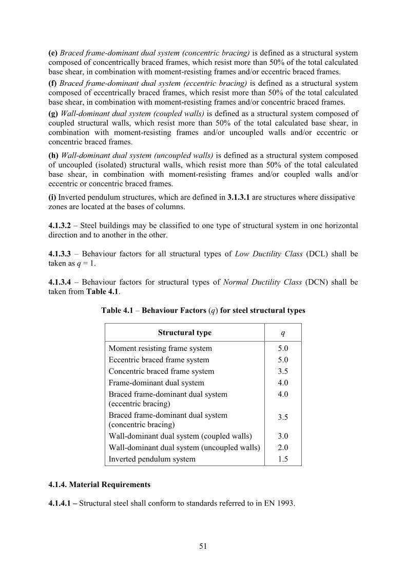
51
(e) Braced frame-dominant dual system (concentric bracing) is defined as a structural system
composed of concentrically braced frames, which resist more than 50% of the total calculated
base shear, in combination with moment-resisting frames and/or eccentric braced frames.
(f) Braced frame-dominant dual system (eccentric bracing) is defined as a structural system
composed of eccentrically braced frames, which resist more than 50% of the total calculated
base shear, in combination with moment-resisting frames and/or concentric braced frames.
(g) Wall-dominant dual system (coupled walls) is defined as a structural system composed of
coupled structural walls, which resist more than 50% of the total calculated base shear, in
combination with moment-resisting frames and/or uncoupled walls and/or eccentric or
concentric braced frames.
(h) Wall-dominant dual system (uncoupled walls) is defined as a structural system composed
of uncoupled (isolated) structural walls, which resist more than 50% of the total calculated
base shear, in combination with moment-resisting frames and/or coupled walls and/or
eccentric or concentric braced frames.
(i) Inverted pendulum structures, which are defined in 3.1.3.1 are structures where dissipative
zones are located at the bases of columns.
4.1.3.2 – Steel buildings may be classified to one type of structural system in one horizontal
direction and to another in the other.
4.1.3.3 – Behaviour factors for all structural types of Low Ductility Class (DCL) shall be
taken as q = 1.
4.1.3.4 – Behaviour factors for structural types of ormal Ductility Class (DCN) shall be
taken from Table 4.1.
Table 4.1 – Behaviour Factors (q) for steel structural types
Structural type q
Moment resisting frame system
Eccentric braced frame system
Concentric braced frame system
Frame-dominant dual system
Braced frame-dominant dual system
(eccentric bracing)
Braced frame-dominant dual system
(concentric bracing)
Wall-dominant dual system (coupled walls)
Wall-dominant dual system (uncoupled walls)
Inverted pendulum system
5.0
5.0
3.5
4.0
4.0
3.5
3.0
2.0
1.5
4.1.4. Material Requirements
4.1.4.1 – Structural steel shall conform to standards referred to in EN 1993.

52
4.1.4.2 – The toughness of the steels and the welds should satisfy the requirements for the
seismic action at the quasi-permanent value of the service temperature (see EN 1993-1-
10:2004).
4.1.4.3 – In bolted connections of primary seismic members of a building, high strength bolts
of bolt grade 8.8 or 10.9 should be used.
4.1.4.4 – In the capacity design checks specified in 4.2 to 4.5, the possibility that the actual
yield strength of steel is higher than the nominal yield strength should be taken into account
by a material overstrength factor γov = 1.25.

53
4.2. GEERAL DESIG CRITERIA AD DETAILIG RULES
4.2.1. Design rules for ductile elements in compression or bending
4.2.1.1 – Sufficient local ductility of members which dissipate energy in compression or
bending shall be ensured by restricting the width-thickness ratio b/t according to the cross-
sectional classes specified in EN 1993-1-1:2004, 5.5.
4.2.1.2 – Depending on the ductility class and the behaviour factor q used in the design, the
requirements regarding the cross-sectional classes of the steel elements which dissipate
energy are indicated in Table 4.2.
Table 4.2. Required cross-sectional class
Behaviour Factor
q
Cross-sectional
class
1.5 < q ≤ 2 Class 1,2 or 3
2 < q ≤ 4 Class 1 or 2
4.2.2. Design rules for ductile elements in tension
For tension members or parts of members in tension, the ductility requirement of EN 1993-1-
1:2004, 6.2.3(3) should be met.
4.2.3. Design rules for connections
4.2.3.1 – For fillet weld or bolted connections, Eq.(4.1) should be satisfied:
d ov fy 1.1R R≥ γ (4.1)
4.2.3.2 – Categories B and C of bolted joints in shear in accordance with EN 1993-1-8:2004,
3.4.1 and category E of bolted joints in tension in accordance with EN 1993-1-8:2004, should
be used. Shear joints with fitted bolts are also allowed. Friction surfaces should belong to
class A or B as defined in ENV 1090-1.
4.2.3.3 – For bolted shear connections, the design shear resistance of the bolts should be
higher than 1.2 times the design bearing resistance.
54
4.3. DESIG AD DETAILIG RULES FOR MOMET RESISTIG FRAMES
4.3.1. Design criteria
4.3.1.1 – Moment resisting frames shall be designed so that plastic hinges form in the beams
or in the connections of the beams to the columns, but not in the columns, in accordance with
4.3.1.2.
4.3.1.2 – In moment resisting frame systems, including frame-dominant dual systems as
defined in 4.1.3.1, the following condition should be satisfied at all beam-column joints:
Rc Rb 1.3 M M≥∑ ∑ (4.2)
4.3.1.3 – Slab reinforcement parallel to the beam and within the effective flange width shall
be considered to contribute to the beam flexural capacities taken into account for the
calculation of RbM∑ in Eq.(4.2), if it is anchored beyond the beam section at the face of the
joint.
4.3.1.4 – Eq.(4.2) shall be satisfied separately for both earthquake directions and senses with
the column moments always opposing the beam moments to yield the most unfavourable
result. In calculating the column moment resistances, axial forces shall be taken to yield the
minimum moments consistent with the sense of earthquake direction.
4.3.1.5 – If the structural system is a frame or equivalent to a frame in only one of the two
main horizontal directions of the structural system, then Eq.(4.2) should be satisfied just
within the vertical plane through that direction.
4.3.1.6 – Special situations regarding the application of Eq.(4.2) are given in the following:
(a) Eq.(4.2) need not to be satisfied at the base of any frame.
(b) Eq.(4.2) need not to be checked in single storey buildings and in joints of topmost storey
of multi-storey buildings.
4.3.1.7 – Eq.(4.2) may be permitted not to be satisfied in a given earthquake direction at a
certain number of joints at the bottom and/or top of a storey, provided that Eq.(4.3) holds.
isi
ic
= 0.75V
Vα ≥ (4.3)
4.3.1.8 – In the case where Eq.(4.3) is satisfied, bending moments and shears of columns
satisfying Eq.(4.2) at both bottom and top joints shall be amplified by multiplying with the
ratio (1/αi) within the range of 0.75 ≤ αi < 1.00.
4.3.2. Beams
4.3.2.1 – Beams should be verified as having sufficient resistance against lateral and lateral
torsional buckling in accordance with EN 1993, assuming the formation of a plastic hinge at
one end of the beam. The beam end that should be considered is the most stressed end in the
seismic design situation.

55
4.3.2.2 – For plastic hinges in the beams it should be verified that the full plastic moment of
resistance and rotation capacity are not decreased by compression and shear forces. To this
end, for sections belonging to cross-sectional classes 1 and 2, the following inequalities
should be verified at the location where the formation of hinges is expected:
Ed
pl,Rd
Ed
pl,Rd
Ed
pl,Rd
1.0
0.15
0.5
M
M
V
V
≤
≤
≤
(4.4)
where
pl,Rd,A pl,Rd,B
Ed Ed,G Ed,M Ed,M = ; = M M
V V V VL
++ (4.5)
For sections belonging to cross-sectional class 3, pl,Rd , Mpl,Rd , Vpl,Rd must be replaced with
el,Rd , Mel,Rd , Vel,Rd in Eq.(4.4) and Eq.(4.5).
4.3.2.3 – The condition in the second expression of Eq.(4.4) may not be verified, provided
that the provisions of EN 1993-1-1:2004,6.2.9.1 are satisfied.
4.3.3. Columns
4.3.3.1 – The columns shall be verified in compression considering the most unfavourable
combination of the axial force and bending moments. ed , Med , Ved shall be calculated as:
Ed Ed,G ov Ed,E
Ed Ed,G ov Ed,E
Ed Ed,G ov Ed,E
= +1.1
= +1.1
= +1.1
M M M
V V V
γ Ω
γ Ω
γ Ω
(4.6)
where Ω is the minimum value of Ωi = Mpl,Rd,i / MEd,i of all beams, MEd,i is the design value of
the bending moment in beam i in the seismic design situation and Mpl,Rd,i is the corresponding
plastic moment.
4.3.3.2 – The resistance verification of the columns should be made in accordance with EN
1993-1-1:2004, Section 6.
4.3.3.3 – The column shear force VEd resulting from the structural analysis should satisfy the
following expression :
Ed
pl,Rd
0.5V
V≤ (4.7)
4.3.3.4 – The transfer of the forces from the beams to the columns should conform to the
design rules given in EN 1993-1-1:2004, Section 6.
4.3.3.5 – The shear resistance of framed web panels of beam/column connections should
satisfy the following expression:

56
wp,Ed
wp,Rd
1.0V
V≤ (4.8)
where Vwp,Ed is the design shear force in the web panel due to the action effects, taking into
account the plastic resistance of the adjacent beams or connections; Vwp,Rd is the shear
resistance of the web panel in accordance with EN 1993- 1-8:2004, 6.2.4.1. It is not required
to take into account the effect of the stresses of the axial force and bending moment on the
plastic resistance in shear.
4.3.3.6 – The shear buckling resistance of the web panels should also be checked to ensure
that it conforms to EN 1993-1-5:2004, Section 5:
wp,Ed
wb,Rd
1.0V
V≤ (4.9)
where Vwb,Rd is the shear buckling resistance of the web panel.
4.3.4. Beam - column connections
4.3.4.1 – If the structure is designed to dissipate energy in the beams, the connections of the
beams to the columns should be designed for the required degree of overstrength taking into
account the moment of resistance Mpl,Rd and the shear force (Ved,G + Ved,M) evaluated in
4.3.2.2.
4.3.4.2 – Energy dissipating semi-rigid and/or partial strength connections are permitted,
provided that all of the following requirements are verified:
(a) Connections have a rotation capacity consistent with the global deformations
(b) Members framing into the connections are demonstrated to be stable at the ultimate limit
state (ULS);
(c) Effect of connection deformation on global drift is taken into account using nonlinear
static (pushover) global analysis or non-linear response history analysis.
4.3.4.3 – The connection design should be such that the chord rotation capacity of the plastic
hinge region θp is not less than 25 mrad for structures with q > 2.
4.3.4.4 – In experiments made to assess θp the column web panel shear resistance should
conform to Eq.(4.7) and the column web panel shear deformation should not contribute for
more than 30% of the plastic rotation capability θp.
4.3.4.5 – The column elastic deformation should not be included in the evaluation of θp.
4.3.4.6 – When partial strength connections are used, the column capacity design should be
derived from the plastic capacity of the connections.
57
4.4. DESIG AD DETAILIG RULES FOR FRAMES WITH COCETRIC
BRACIGS
4.4.1. Design criteria
4.4.1.1 – Concentric braced frames shall be designed so that yielding of the diagonals in
tension will take place before failure of the connections and before yielding or buckling of the
beams or columns.
4.4.1.2 – Diagonal elements of bracings shall be placed in such a way that the structure
exhibits similar load deflection characteristics at each storey in opposite senses of the same
braced direction under load reversals. In this regard, the following rule should be met at every
storey:
0.05A A
A A
+ −
+ −
−≤
+ (4.10)
where A+ and A
– are the areas of the horizontal projections of the cross-sections of the tension
diagonals, when the horizontal seismic actions have a positive or negative direction
respectively.
4.4.2 Analysis
4.4.2.1 – Under gravity load conditions, only beams and columns shall be considered to resist
such loads, without taking into account the bracing members.
4.4.2.2 – Diagonals shall be taken into account as follows in an elastic analysis of the
structure for the seismic action:
(a) In frames with diagonal bracings, only the tension diagonals shall be taken into account.
(b) In frames with V bracings, both the tension and compression diagonals shall be taken into
account.
4.4.2.3 – Taking into account of both tension and compression diagonals in the analysis of
any type of concentric bracing is allowed provided that all of the following conditions are
satisfied:
(a) Non-linear static (pushover) global analysis or non-linear time history analysis is used,
(b) both pre-buckling and post-buckling situations are taken into account in the modelling of
the behaviour of diagonals and,
(c) background information justifying the model used to represent the behaviour of diagonals
is provided.
4.4.3 Diagonal members
4.4.3.1 – In frames with X diagonal bracings, the non-dimensional slenderness λ as defined
in EN 1993-1-1:2004 should be limited to: 1.3 < λ ≤ 2.0.
4.4.3.2 – In frames with diagonal bracings in which the diagonals are not positioned as X
diagonal bracings, the non-dimensional slenderness λ should be less than or equal to 2.0.

58
4.4.3.3 – In frames with V bracings, the non-dimensional slenderness λ should be less than or equal to 2.0.
4.4.3.4 – In structures of up to two storeys, no limitation applies to λ .
4.4.3.5 – Yield resistance pl,Rd of the gross cross-section of the diagonals should be such that
pl,Rd ≥ Ed .
4.4.3.6 – In frames with V bracings, the compression diagonals should be designed for the
compression resistance in accordance with EN 1993.
4.4.3.7 – The connections of the diagonals to any member should satisfy the design rules of
4.2.3.
4.4.3.8 – In order to satisfy a homogeneous dissipative behaviour of the diagonals, it should
be checked that the maximum overstrength Ωi defined in 4.4.4.1 does not differ from the
minimum value Ω by more than 25%.
4.4.3.9 – Energy dissipating semi-rigid and/or partial strength connections are permitted,
provided that all of the following conditions are satisfied:
(a) Connections have an elongation capacity consistent with global deformations;
(b) Effect of connections deformation on global drift is taken into account using nonlinear
static (pushover) global analysis or non-linear time history analysis.
4.4.4 Beams and columns
4.4.4.1 – Beams and columns with axial forces should meet the following minimum resistance
requirement:
pl,Rd Ed Ed,G ov Ed,E ( ) +1.1 M ≥ γ Ω (4.11)
where pl,Rd(MEd) is the design buckling resistance of the beam or the column in accordance
with EN 1993, taking into account the interaction of the buckling resistance with the bending
moment MEd , defined as its design value in the seismic design situation; Ed,G is the axial
force in the beam or in the column due to the non-seismic actions included in the combination
of actions for the seismic design situation; Ed,E is the axial force in the beam or in the
column due to the design seismic action; γov is the overstrength factor, Ω is the minimum
value of Ωi = pl,Rd,i / Ed,i over all the diagonals of the braced frame system; where pl,Rd,i is
the design resistance of diagonal i; Ed,i is the design value of the axial force in the same
diagonal i in the seismic design situation.
4.4.4.2 – In frames with V bracings, the beams should be designed to resist:
(a) all non-seismic actions without considering the intermediate support given by the
diagonals;
(b) unbalanced vertical seismic action effect applied to the beam by the braces after buckling
of the compression diagonal. This action effect is calculated using pl,Rd for the brace in
tension and γpb pl,Rd for the brace in compression (The factor γpb is used for the estimation of
the post buckling resistance of diagonals in compression, which may be taken as 0.3).

59
4.4.4.3 – In frames with diagonal bracings where tension and compression diagonals are not
intersecting, the design should take into account the tensile and compression forces which
develop in the columns adjacent to the diagonals in compression and correspond to
compression forces in these diagonals equal to their design buckling resistance.

60
4.5. DESIG AD DETAILIG RULES FOR FRAMES WITH ECCETRIC
BRACIGS
4.5.1. Design criteria
4.5.1.1 – Frames with eccentric bracings shall be designed so that specific elements or parts of
elements called seismic links are able to dissipate energy by the formation of plastic bending
and/or plastic shear mechanisms.
4.5.1.2 – Seismic links may be horizontal or vertical components.
4.5.2. Seismic links
4.5.2.1 – The web of a link should be of single thickness without doubler plate reinforcement
and without a hole or penetration.
4.5.2.2 – Seismic links are classified into 3 categories according to the type of plastic
mechanism developed:
(a) Short links, which dissipate energy by yielding essentially in shear;
(b) Long links, which dissipate energy by yielding essentially in bending;
(c) Intermediate links, in which the plastic mechanism involves bending and shear.
4.5.2.3 – For I sections, the following parameters are used to define the design resistances and
limits of categories:
p,link y f f = ( )M f b t d t− (4.12)
p,link y w f = ( 3) ( )V f t d t−/ (4.13)
4.5.2.4 – If Ed / pl,Rd ≤ 0.15, the design resistance of the link should satisfy both of the
following relationships at both ends of the link:
Ed p,link
Ed p,link
V V
M M
≤
≤ (4.14)
where Ed , MEd , VEd are the design axial force, design bending moment and design shear,
respectively, at both ends of the link.
4.5.2.5 – If Ed / pl,Rd > 0.15, Eqs.(4.14) should be satisfied with the following reduced
values Vp,link,r and Mp,link,r used instead of Vp,link and Mp,link :
2,r Ed pl,Rdp,link p,link
,r Ed pl,Rdp,link p,link
= 1 ( )
= (1 )
V V
M M
−
−
/
/ (4.15)
4.5.2.6 – If Ed / pl,Rd ≤ 0.15, link length e should not exceed:

61
p,link
p,link
p,link
p,link
1 6 (if 0.3)
1 6 (1.15 0.5 ) (if 0.3)
Me R
V
Me R R
V
≤ <
≤ − ≥
.
.
(4.16)
where
Ed w f
Ed
( 2 )= t d t
RV A
− (4.17)
in which A is the gross area of the link.
4.5.2.7 – To achieve a global dissipative behaviour of the structure, it should be checked that
the individual values of the ratios Ωi defined in 4.5.2.1 do not exceed the minimum value Ω resulting from 4.5.2.1 by more than 25% of this minimum value.
4.5.2.8 – When equal moments develop simultaneously at both ends of the link, links may be
classified according to the length e. For I sections, the categories are:
p,links
p,link
p,linkL
p,link
s L
Short links: = 1 6
Long links: = 3 0
Intermediate links:
Me e
V
Me e
V
e e e
≤
>
< <
.
. (4.18)
4.5.2.9 – When only one plastic hinge develops at one end of the link, the value of the length
e defines the categories of the links. For I sections the categories are:
p,links
p,link
p,linkL
p,link
s L
Short links: = 0.8(1+ )
Long links: = 1.5(1+ )
Intermediate links:
Me e
V
Me e
V
e e e
≤ α
> α
< <
(4.19)
where α is the ratio of the smaller bending moments MEd,A at one end of the link in the
seismic design situation, to the greater bending moments MEd,B at the end where the plastic
hinge develops, both moments being taken as absolute values.
4.5.2.10 – The link rotation angle θp between the link and the element outside of the link as
defined in 4.3.4.3 should be consistent with global deformations. It should not exceed the
following values:
p pR
p pR
p pR
Short links: = 0.08 radian
Long links: = 0.02 radian
Intermediate links: = by interpolation
θ ≤ θ
θ ≤ θ
θ ≤ θ
(4.20)

62
4.5.2.11 – Full-depth web stiffeners should be provided on both sides of the link web at the
diagonal brace ends of the link. These stiffeners should have a combined width of not less
than (bf – 2tw) and a thickness not less than 0.75 tw nor 10 mm, whichever is larger.
4.5.2.12 – Links should be provided with intermediate web stiffeners as follows:
(a) Short links should be provided with intermediate web stiffeners spaced at intervals not
exceeding (30tw – d/5) for a link rotation angle θp of 0.08 radians or (52tw – d/5) for link
rotation angles θp of 0.02 radians or less. Linear interpolation should be used for values of θp
between 0.08 and 0.02 radians;
(b) Long links should be provided with one intermediate web stiffener placed at a distance of
1.5 times b from each end of the link where a plastic hinge would form;
(c) Intermediate links should be provided with intermediate web stiffeners meeting the
requirements of (a) and (b) above;
(d) Intermediate web stiffeners are not required in links of length e greater than 5 Mp/Vp;
(e) intermediate web stiffeners should be full depth. For links that are less than 600 mm in
depth d, stiffeners are required on only one side of the link web. The thickness of one-sided
stiffeners should be not less than tw or 10 mm, whichever is larger, and the width should be
not less than (b/2) – tw . For links that are 600 mm in depth or greater, similar intermediate
stiffeners should be provided on both sides of the web.
4.5.2.13 – Fillet welds connecting a link stiffener to the link web should have a design
strength adequate to resist a force of γov fy Ast , where Ast is the area of the stiffener. The
design strength of fillet welds fastening the stiffener to the flanges should be adequate to resist
a force of γov fy Ast / 4.
4.5.2.14 – Lateral supports should be provided at both the top and bottom link flanges at the
ends of the link. End lateral supports of links should have a design axial resistance sufficient
to provide lateral support for forces of 6% of the expected nominal axial strength of the link
flange computed as fy b tf .
4.5.2.15 – In beams where a seismic link is present, the shear buckling resistance of the web
panels outside of the link should be checked to conform to EN 1993-1-5:2004, Section 5.
4.5.3. Members not containing seismic links
The members not containing seismic links, like the columns and diagonal members, if
horizontal links in beams are used, and also the beam members, if vertical links are used,
should be verified in compression considering the most unfavourable combination of the axial
force and bending moments:
Rd Ed Ed Ed,G ov Ed,E ( , ) +1.1 M ≥ γ Ω (4.21)
where Rd(MEd , Ed) is the axial design resistance of the column or diagonal member in
accordance with EN 1993, taking into account the interaction with the bending moment MEd
and the shear VEd taken at their design value in the seismic situation; Ed,G is the compression
force in the column or diagonal member due to the nonseismic actions included in the
combination of actions for the seismic design situation; Ed,E is the compression force in the
column or diagonal member due to the design seismic action; γov is the overstrength factor Ω

63
is a multiplicative factor which is the minimum of the following values: the minimum value
of Ωi = 1.5 (Vp,link,i / VEd,i) among all short links; the minimum value of Ωi = 1.5(Mp,link,i / MEd,i)
among all intermediate and long links; where VEd,i , MEd,i are the design values of the shear
force and of the bending moment in link i in the seismic design situation; Vp,link,i , Mp,link,i are
the shear and bending plastic design resistances of link i as in 4.5.2.3.
4.5.4. Connections of seismic links
4.5.4.1 – If the structure is designed to dissipate energy in the seismic links, the connections
of the links or of the element containing the links should be designed for action effects Ed
computed as follows:
d d,G ov d,E +1.1E E ≥ γ Ω (4.22)
where Ed,G is the action effect in the connection due to the non-seismic actions included in the
combination of actions for the seismic design situation; Ed,E is the action effect in the
connection due to the design seismic action; γov is the overstrength factor, Ωi is the
overstrength factor computed in accordance with 4.5.3 for the link.
4.5.4.2 – In the case of semi-rigid and/or partial strength connections, the energy dissipation
may be assumed to originate from the connections only. This is allowable, provided that all of
the following conditions are satisfied:
(a) the connections have rotation capacity sufficient for the corresponding deformation
demands;
(b) members framing into the connections are demonstrated to be stable at the ULS;
(c) the effect of connection deformations on global drift is taken into account.
4.5.4.3 – When partial strength connections are used for the seismic links, the capacity design
of the other elements in the structure should be derived from the plastic capacity of the links
connections.

64
4.6. DESIG RULES FOR STEEL BUILDIGS WITH COCRETE CORES OR
COCRETE WALLS
4.6.1 – The steel elements shall be verified in accordance with this Chapter and EN 1993,
while the concrete elements shall be designed in accordance with Chapter 3.
4.6.2 – The elements in which an interaction between steel and concrete exists shall be
verified in accordance with Chapter 5.
65
4.7. DESIG RULES FOR IVERTED PEDULUM STRUCTURES
4.7.1 – In inverted pendulum structures (defined in 4.1.3.1), the columns should be verified in
compression considering the most unfavourable combination of the axial force and bending
moments.
4.7.2 – In the checks, Ed, MEd, VEd should be computed as in 4.3.3.
4.7.3 – The non-dimensional slenderness of the columns should be limited to λ ≤ 1,5.
66
CHAPTER 5
SEISMIC DESIG REQUIREMETS FOR
STEEL – COCRETE COMPOSITE BUILDIGS
5.1. SCOPE AD DESIG COCEPTS
5.1.1. Scope
5.1.1.1 – This Chapter applies to the seismic design of elements of composite steel-concrete
buildings.
5.1.1.2 – The rules given in this Chapter are additional to those given in EN 1994-1-1:2004.
5.1.1.3 – Except where modified by the provisions of this Chapter, the provisions of Chapters
3 and 4 apply.
5.1.2. Design Concepts
5.1.2.1 – Earthquake resistant composite buildings shall be designed in accordance with one
of the following design concepts (see Table 5.1):
(a) Concept A: Low-dissipative structural behaviour.
(b) Concept B: Dissipative structural behaviour with composite dissipative zones;
(c) Concept C: Dissipative structural behaviour with steel dissipative zones.
Table 5.1. Design concepts of composite buildings
Design concept Structural
ductility class
Behaviour
factor q
A: Low dissipative structural behaviour DCL 1.0
B or C: Dissipative structural behaviour DCN ≤ 5.0
5.1.2.2 – In concept A, the action effects may be calculated on the basis of an elastic analysis
without taking into account non-linear material behaviour but considering the reduction in the
moment of inertia due to the cracking of concrete in part of the beam spans, in accordance
with the general structural analysis rules defined in 5.2 and to the specific rules defined in 5.5
to 5.9 related to each structural type. Behaviour factor shall be taken as q = 1.
5.1.2.3 – In concept A the resistance of the members and of the connections should be
evaluated in accordance with EN 1993 and EN 1994 without any additional requirements.
5.1.2.4 – In concepts B and C, the capability of parts of the structure (dissipative zones) to
resist earthquake actions through inelastic behaviour is taken into account. Behavior factor
shall be taken from Table 5.2. When adopting concepts B or C the requirements given in 5.2
to 5.9 should be fulfilled.
5.1.2.5 – In concept C, structures are not meant to take advantage of composite behaviour in
dissipative zones; the application of concept C is conditioned by a strict compliance to
measures that prevent involvement of the concrete in the resistance of dissipative zones. In
67
concept C the composite structure is designed in accordance with EN 1994-1-1:2004 under
non-seismic loads and in accordance with Chapter 4 to resist earthquake action. The
measures preventing involvement of the concrete are given in 5.5.5.
5.1.2.6 – The design rules for dissipative composite structures (concept B), aim at the
development of reliable local plastic mechanisms (dissipative zones) in the structure and of a
reliable global plastic mechanism dissipating as much energy as possible under the design
earthquake action. For each structural element or each structural type considered in this
Chapter, rules allowing this general design objective to be achieved are given in 5.5 to 5.9
with reference to what are called the specific criteria. These criteria aim at the development of
a global mechanical behaviour for which design provisions can be given.
5.1.2.7 – Structures designed in accordance with concept B shall belong to structural ductility
class identified as ormal Ductility Class (DCN). This ductility class corresponds to
increased ability of the structure to dissipate energy in plastic mechanisms, for which
composite seismic design requirements are given in the remainder of Chapter 5.
5.1.3. Structural types and Behaviour Factors
5.1.3.1 – Composite steel-concrete structures shall be assigned to one of the following
structural types according to the behaviour of their primary resisting structure under seismic
actions:
(a) Composite moment resisting frames are those with the same definition and limitations as
in 4.1.3.1(a), but in which beams and columns may be either structural steel or composite
steel-concrete.
(b) Composite concentrically braced frames are those with the same definition and limitations
as in 4.1.3.1(b). Columns and beams may be either structural steel or composite steel-
concrete. Braces shall be structural steel.
(c) Composite eccentrically braced frames are those with the same definition and
configurations as in 4.1.3.1(c). The members which do not contain the links may be either
structural steel or composite steel-concrete. Other than for the slab, the links shall be
structural steel. Energy dissipation shall occur only through yielding in bending or shear of
these links.
(d) Inverted pendulum structures, have the same definition and limitations as in 4.1.3.1(i).
(e) Composite structural systems are those which behave essentially as reinforced concrete
walls. The composite systems may belong to one of the following types:
− Type 1 corresponds to a steel or composite frame working together with concrete infill
panels connected to the steel structure;
− Type 2 is a reinforced concrete wall in which encased steel sections connected to the
concrete structure are used as vertical edge reinforcement;
− Type 3, steel or composite beams are used to couple two or more reinforced concrete or
composite walls.
(f) Composite steel plate shear walls are those consisting of a vertical steel plate continuous
over the height of the building with reinforced concrete encasement on one or both faces of
the plate and of the structural steel or composite boundary members.
68
5.1.3.2 – In all types of composite structural systems the energy dissipation takes place in the
vertical steel sections and in the vertical reinforcements of the walls. In type 3 composite
structural systems, energy dissipation may also take place in the coupling beams.
5.1.3.3 – If, in composite structural systems the wall elements are not connected to the steel
structure, Chapters 3 and 4 apply.
5.1.3.4 – The behaviour factor q shall be taken from Table 4.1 or Table 5.2 as indicated in
the latter, provided that the rules in 5.3 to 5.9 are met.
Table 5.2. Behaviour Factors (q) for composite structural types
Structural type q
Composite moment resisting frame system
Composite eccentrically braced frame system
Composite concentrically braced frame system
Frame-dominant dual system
Braced frame-dominant dual system (eccentric
bracing)
Braced frame-dominant dual system (concentric
bracing)
Inverted pendulum system
5.0
5.0
3.5
4.0
4.0
3.5
1.5
Composite walls (Type 1 and Type 2)
Composite or concrete walls coupled by steel
or composite beams (Type 3)
3.5
3.5
Composite steel plate structural walls 3.5
5.1.4. Material requirements
5.1.4.1 – In dissipative zones, the prescribed concrete class should not be lower than C20/25.
If the concrete class is higher than C40/50, the design is not within the scope of EN 1998-1.
5.1.4.2 – For ductility class DCN the reinforcing steel taken into account in the plastic
resistance of dissipative zones shall be of class B or C in accordance with EN 1992-1-1:2004
Table C.1.
5.1.4.3 – Reinforcing steel of class B or C ( EN 1992-1-1:2004, Table C.1) shall be used in
highly stressed regions of non dissipative structures. This requirement applies to both bars and
welded meshes.
5.1.4.4 – Except for closed stirrups or cross ties, only ribbed bars are allowed as reinforcing
steel in regions with high stresses.
5.1.4.5 – Welded meshes not conforming to the requirements of 5.1.4.2 shall not be used in
dissipative zones. If such meshes are used, ductile reinforcement duplicating the mesh should
be placed and their resistance capacity accounted for in the capacity analysis.

69
5.1.4.6 – For structural steel, requirements given in 4.1.4 apply.

70
5.2. STRUCTURAL AALYSIS
5.2.1. Scope
The following rules apply to the analysis of the structure under earthquake action with
Equivalent Seismic Load Method given in 2.3 and with the Multi-Mode Response Spectrum
Analysis Method given in 2.4.
5.2.2. Stiffness of sections
5.2.2.1 – The stiffness of composite sections in which the concrete is in compression shall be
computed using a modular ratio n given in Eq.(5.1).
a
cm
7E
nE
= = (5.1)
5.2.2.2 – For composite beams with slab in compression, the second moment of area of the
section, referred to as I1, shall be computed taking into account the effective width of slab
defined in 5.4.3.
5.2.2.3 – The stiffness of composite sections in which the concrete is in tension shall be
computed assuming that the concrete is cracked and that only the steel parts of the section are
active.
5.2.2.4 – For composite beams with slab in tension, the second moment of area of the section,
referred to as I2, shall be computed taking into account the effective width of slab defined in
5.4.3
5.2.2.5 – The structure should be analysed taking into account the presence of concrete in
compression in some zones and concrete in tension in other zones; the distribution of the
zones is given in 5.5 to 5.9 for the various structural types.
71
5.3. DESIG CRITERIA AD DETAILIG RULES FOR DISSIPATIVE
STRUCTURAL BEHAVIOUR COMMO TO ALL STRUCTURAL TYPES
5.3.1. Design criteria for dissipative structures
5.3.1.1 – Dissipative zones shall have adequate ductility and resistance. The resistance shall
be determined in accordance with EN 1993-1-1:2004 and Chapter 4 for concept C, and to EN
1994-1-1:2004 and Chapter 5 for concept B (see 5.1.2.1). Ductility is achieved by
compliance to detailing rules.
5.3.1.2 – Dissipative zones may be located in the structural members or in the connections.
(a) If dissipative zones are located in the structural members, the non-dissipative parts and the
connections of the dissipative parts to the rest of the structure shall have sufficient
overstrength to allow the development of cyclic yielding in the dissipative parts.
(b) When dissipative zones are located in the connections, the connected members shall have
sufficient overstrength to allow the development of cyclic yielding in the connections.
5.3.2. Plastic resistance of dissipative zones
5.3.2.1 – Two plastic resistances of dissipative zones are used in the design of composite steel
- concrete structures: a lower bound plastic resistance (index: pl,Rd) and an upper bound
plastic resistance (index: U,Rd).
5.3.2.2 – The lower bound plastic resistance of dissipative zones is the one taken into account
in design checks concerning sections of dissipative elements; e.g. MEd < Mpl,Rd . The lower
bound plastic resistance of dissipative zones is computed taking into account the concrete
component of the section and only the steel components of the section which are classified as
ductile.
5.3.2.3 – The upper bound plastic resistance of dissipative zones is the one used in the
capacity design of elements adjacent to the dissipative zone: for instance in the capacity
design verification of 4.3.1.2, the design values of the moments of resistance of beams are the
upper bound plastic resistances, MU,Rd,b , whereas those of the columns are the lower bound
ones, Mpl,Rd,c .
5.3.2.4 – The upper bound plastic resistance is computed taking into account the concrete
component of the section and all the steel components present in the section, including those
that are not classified as ductile.
5.3.2.5 – Action effects, which are directly related to the resistance of dissipative zones, shall
be determined on the basis of the upper bound resistance of composite dissipative sections;
e.g. the design shear force at the end of a dissipative composite beam shall be determined on
the basis of the upper bound plastic moment of the composite section.
5.3.3. Detailing rules for composite connections in dissipative zones
5.3.3.1 – For the design of welds and bolts, 4.2.3 applies.

72
5.3.3.2 – In fully encased framed web panels of beam/column connections, the panel zone
resistance may be computed as the sum of contributions from the concrete and steel shear
panel, if all the following conditions are satisfied:
b c0.6 < / < 1.4h h (5.2)
wp,Ed wp,Rd< 0.8V V (5.3)
where hb / hc is the aspect ratio of the panel zone; where Vwp,Ed is the design shear force in the
web panel due to the action effects, taking into account the plastic resistance of the adjacent
composite dissipative zones in beams or connections; Vwp,Rd is the shear resistance of the
composite steel - concrete web panel in accordance with EN 1994-1-1:2004.
5.3.3.3 – In partially encased stiffened web panels, an assessment similar to that in 5.3.3.2 is
permitted if, in addition to the requirements of 5.3.3.4, one of the following conditions is
fulfilled:
(a) Straight links of the type defined in 5.4.5.4 and complying with 5.4.5.5 and 5.4.5.6 are
provided at a maximum spacing sl = c in the partially encased stiffened web panel; these links
are oriented perpendicularly to the longest side of the column web panel and no other
reinforcement of the web panel is required; or
(b) No reinforcement is present, provided that hb / bb < 1,2 and hc / bc < 1,2.
5.3.3.4 – When a dissipative steel or composite beam is framing into a reinforced concrete
column, vertical column reinforcement with design axial strength at least equal to the shear
strength of the coupling beam should be placed close to the stiffener or face bearing plate
adjacent to the dissipative zone. It is permitted to use vertical reinforcement placed for other
purposes as part of the required vertical reinforcement. The presence of face bearing plates is
required; they should be full depth stiffeners of a combined width not less than (bb – 2 t); their
thickness should be not less than 0,75 t or 8 mm; bb and t are respectively the beam flange
width and the panel web thickness.
5.3.3.5 – When a dissipative steel or composite beam is framing into a fully encased
composite column, the beam column connection may be designed either as a beam/steel
column connection or a beam/composite column connection. In the latter case, vertical
column reinforcements may be calculated either as in 5.3.3.4 or by distributing the shear
strength of the beam between the column steel section and the column reinforcement. In both
instances, the presence of face bearing plates as described in 5.3.3.4 is required.
5.3.3.6 – The vertical column reinforcement specified in 5.3.3.4 and 5.3.3.5 should be
confined by transverse reinforcement that meets the requirements for members defined in 5.4.

73
5.4. RULES FOR MEMBERS
5.4.1. General
5.4.1.1 – Composite members, which are primary seismic members, shall conform to EN
1994-1-1:2004 and to additional rules defined in this Section.
5.4.1.2 – For tension members or parts of members in tension, the ductility requirement of EN
1993-1-1:2004, 6.2.3(3) should be met.
5.4.1.3 – Sufficient local ductility of members which dissipate energy under compression
and/or bending should be ensured by restricting the width-to-thickness ratios of their walls.
Steel dissipative zones and the not encased steel parts of composite members should meet the
requirements of 4.2.1.1 and Table 4.2. Dissipative zones of encased composite members
should meet the requirements of Table 5.3. The limits given for flange outstands of partially
or fully encased members may be relaxed if special details are provided as described in
5.4.4.9 and 5.4.5.4 to 5.4.5.6.
Table 5.3. Limits of wall slenderness
Section type Wall
slenderness
Partially encased H or I section
Fully encased H or I section
Flange outstand limits c / tf :
14 ε
Filled rectangular section
h / t limits:
38 ε
Filled circular section
d / t limits:
85 ε2
where ε = (fy / 235)0.5
5.4.1.4 – More specific detailing rules for dissipative composite members are given in 5.4.2,
5.4.4, 5.4.5 and 5.4.6.
5.4.1.5 – In the design of all types of composite columns, the resistance of the steel section
alone or the combined resistances of the steel section and the concrete encasement or infill
may be taken into account.
5.4.1.6 – The design of columns in which the member resistance is taken to be provided only
by the steel section may be carried out in accordance with the provisions of Chapter 4. In the
case of dissipative columns, the capacity design rules in 5.3.1.2 and 5.3.2.3 should be
satisfied.
5.4.1.7 – For fully encased columns with composite behaviour, the minimum crosssectional
dimensions b, h or d should be not less than 250 mm.
74
5.4.1.8 – The resistance, including shear resistance, of non-dissipative composite columns
should be determined in accordance with the rules of EN 1994-1-1:2004.
5.4.1.9 – In columns, when the concrete encasement or infill are assumed to contribute to the
axial and/or flexural resistance of the member, the design rules in 5.4.4 to 5.4.6 apply. These
rules ensure full shear transfer between the concrete and the steel parts in a section and protect
the dissipative zones against premature inelastic failure.
5.4.1.10 – For earthquake-resistant design, the design shear strength given in EN 1994-1-
1:2004, Table 6.6, should be multiplied by a reduction factor of 0.5.
5.4.1.11 – When, for capacity design purposes, the full composite resistance of a column is
employed, complete shear transfer between the steel and reinforced concrete parts should be
ensured. If insufficient shear transfer is achieved through bond and friction, shear connectors
should be provided to ensure full composite action.
5.4.1.12 – Wherever a composite column is subjected to predominately axial forces, sufficient
shear transfer should be provided to ensure that the steel and concrete parts share the loads
applied to the column at connections to beams and bracing members.
5.4.1.13 – Except at their base in some structural types, columns are generally not designed to
be dissipative. However, because of uncertainties in the behaviour, confining reinforcement is
required in regions called critical regions as specified in 5.4.4.
5.4.1.14 – 3.5.2.1 and 3.5.3 concerning anchorage and splices in the design of reinforced
concrete columns apply also to the reinforcements of composite columns.
5.4.2. Steel beams composite with slab
5.4.2.1 – The design objective of this subclause is to maintain the integrity of the concrete
slab during the seismic event, while yielding takes place in the bottom part of the steel section
and/or in the rebars of the slab.
5.4.2.2 – If it is not intended to take advantage of the composite character of the beam section
for energy dissipation, 5.5.5 shall be applied.
5.4.2.3 – Beams intended to behave as composite elements in dissipative zones of the
earthquake resistant structure may be designed for full or partial shear connection in
accordance with EN 1994-1-1:2004. The minimum degree of connection η as defined in EN
1994-1-1:2004 6.6.1.2 should be not less than 0.8 and the total resistance of the shear
connectors within any hogging moment region not less than the plastic resistance of the
reinforcement.
5.4.2.4 – The design resistance of connectors in dissipative zones is obtained from the design
resistance provided in EN 1994-1-1:2004 multiplied by a reduction factor of 0.75.
5.4.2.5 – Full shear connection is required when non-ductile connectors are used.
5.4.2.6 – When a profiled steel sheeting with ribs transverse to the supporting beams is used,
the reduction factor kt of the design shear resistance of connectors given by EN 1994-1-1

75
should be further reduced by multiplying it by the rib shape efficiency factor kr = 0.8 for the
case of standard trapezoidal ribs.
5.4.2.7 – To achieve ductility in plastic hinges, the ratio x/d of the distance x between the top
concrete compression fibre and the plastic neutral axis, to the depth d of the composite
section, should conform to the following expression:
cu2
cu2 a
<
x
d
εε + ε
(5.4)
where εcu2 is the ultimate compressive strain of concrete (see EN 1992-1-1:2004); εa is the total strain in steel at Ultimate Limit State.
5.4.2.8 – The rule in 5.4.2.7 is deemed to be satisfied when x/d of a section is less than the
limits given in Table 5.4.
Table 5.4. Limit values x/d for
ductility of beams with slabs
fy (MPa) x/d
upper limit
355 0.27
235 0.36
5.4.3. Effective width of slab
5.4.3.1 – The total effective width beff of concrete flange associated with each steel web
should be taken as the sum of the partial effective widths be1 and be2 of the portion of the
flange on each side of the centreline of the steel web. The partial effective width on each side
should be taken as be given in Table 5.5, but not greater than the actual available widths b1 and b2 defined in 5.4.3.2.
5.4.3.2 – The actual width b of each portion should be taken as half the distance from the web
to the adjacent web, except that at a free edge the actual width is the distance from the web to
the free edge.
5.4.3.3 – The partial effective width be of the slab to be used in the determination of the
elastic and plastic properties of the composite T sections made of a steel section connected to
a slab are defined in Table 5.5.
Table 5.5 – I. Partial effective width be of slab for elastic analysis
be Transverse element be for I (elastic)
At interior column Present or not present
At exterior column Present
For negative M: 0.05 l
For positive M: 0.0375 l
At exterior column Not present,
or rebars not anchored
For negative M: 0
For positive M: 0.025 l

76
Table 5.5 – II. Partial effective width be of slab for evaluation of plastic moment
resistance
Sign of bending
moment M Location Transverse element
be for MRd
(plastic)
Negative M Interior
column Seismic re-bars 0.1 l
Negative M Exterior
column
All layouts with re-bars anchored to façade
beam or to concrete cantilever edge strip 0.1 l
Negative M Exterior
column
All layouts with re-bars not anchored to
façade beam or to concrete cantilever edge
strip
0
Positive M Interior
column Seismic re-bars 0.075 l
Positive M Exterior
column
Steel transverse beam with connectors.
Concrete slab up to exterior face of column
of H section with strong axis or beyond
(concrete edge strip). Seismic re-bars
0.075 l
Positive M Exterior
column
No steel transverse beam or steel transverse
beam without connectors.
Concrete slab up to exterior face of column
of H section with strong axis or beyond
(edge strip). Seismic re-bars
bb/2
+
0.7 hc/2
Positive M Exterior
column All other layouts. Seismic re-bars
bb/2 ≤ be,max
be,max=0.05 l
5.4.4. Fully encased composite columns
5.4.4.1 – In dissipative structures, critical regions are present at both ends of all column clear
lengths in moment frames and in the portion of columns adjacent to links in eccentrically
braced frames. The lengths lcr of these critical regions (in metres) are specified by Eq.(3.12),
with hc in these expressions denoting the depth of the composite section (in metres).
5.4.4.2 – To satisfy plastic rotation demands and to compensate for loss of resistance due to
spalling of cover concrete, the following expression should be satisfied within the critical
regions defined above:
cwd d sy,d
o
= 30 0.035
b
bϕαω µ ν ε − (5.5)
in which confinement effectiveness factor α is as defined in 3.3.3.6 and the normalised design
axial force νd is defined as:
Ed Edd
pl,Rd a yd c cd s sd
= =
A f A f A fν
+ + (5.6)
5.4.4.3 – The spacing, s, (in millimetres) of confining hoops in critical regions should not
exceed
o bL min /2 , 260 , 9s b d≤ (5.7)

77
where bo is the minimum dimension of the concrete core (to the centreline of the hoops, in
millimetres); dbL is the minimum diameter of the longitudinal rebars (in millimetres).
5.4.4.4 – The diameter of the hoops shall be at least dbw = 6 mm.
5.4.4.5 – In critical regions, the distance between consecutive longitudinal bars restrained by
hoop bends or cross-ties should not exceed 250 mm.
5.4.4.6 – In the lower two storeys of a building, hoops in accordance with 5.4.4.3, 5.4.4.4 and
5.4.4.5 shall be provided beyond the critical regions for an additional length equal to half the
length of the critical regions.
5.4.4.7 – In dissipative composite columns, the shear resistance should be determined on the
basis of the structural steel section alone.
5.4.4.8 – The relationship between the ductility class of the structure and the allowable
slenderness (c/tf) of the flange outstand in dissipative zones is given in Table 5.3.
5.4.4.9 – Confining hoops can delay local buckling in the dissipative zones. The limits given
in Table 5.3 for flange slenderness may be increased if the hoops are provided at a
longitudinal spacing, s, which is less than the flange outstand: s/c < 1.0. For s/c < 0.5 the
limits given in Table 5.3 may be increased by up to 50%. For values of 0.5 < s/c < 1.0 linear
interpolation may be used.
5.4.4.10 – The diameter dbw of confining hoops used to prevent flange buckling shall be not
less than
ydff
bw
ydw
=
8
fbtd
f (5.8)
in which b and tf are the width and thickness of the flange, respectively, and fydf and fydw are
the design yield strengths of the flange and reinforcement, respectively.
5.4.5. Partially-encased members
5.4.5.1 – In dissipative zones where energy is dissipated by plastic bending of a composite
section, the longitudinal spacing of the transverse reinforcement, s, should satisfy the
requirements of 5.4.4.3 over a length greater or equal to lcr for dissipative zones at the end of a
member and 2lcr for dissipative zones in the member.
5.4.5.2 – In dissipative members, the shear resistance should be determined on the basis of the
structural steel section alone, unless special details are provided to mobilise the shear
resistance of the concrete encasement.
5.4.5.3 – The allowable slenderness (c/t) of the flange outstand in dissipative zones is as given
in Table 5.3.
5.4.5.4 – Straight links welded to the inside of the flanges, as additional to the reinforcements
required by EN 1994-1-1, can delay local buckling in the dissipative zones. In this case, the
limits given in Table 5.3 for flange slenderness may be increased if these bars are provided at
a longitudinal spacing, s1 , which is less than the flange outstand: s1/c < 1.0. For s1/c < 0.5 the

78
limits given in Table 5.3 may be increased by up to 50%. For values of 0.5 < s1/c < 1.0 linear
interpolation may be used. The additional straight links should also conform to the rules in
5.4.5.5 and 5.4.5.6.
5.4.5.5 – The diameter, dbw , of the additional straight links referred to in 5.4.5.4 should be at
least 6 mm. When transverse links are employed to delay local flange buckling as described in
5.4.5.4, dbw should be not less than the value given by Eq.(5.8).
5.4.5.6 – The additional straight links referred to in 5.4.5.4 should be welded to the flanges at
both ends and the capacity of the welds should be not less than the tensile yield strength of the
straight links. A clear concrete cover of at least 20 mm, but not exceeding 40 mm, should be
provided to these links.
5.4.5.7 – The design of partially-encased composite members may take into account the
resistance of the steel section alone, or the composite resistance of the steel section and of
concrete encasement.
5.4.5.8 – The design of partially-encased members in which only the steel section is assumed
to contribute to member resistance may be carried out in accordance with the provisions of
Chapter 4, but the capacity design provisions of 5.3.1.2 and 5.3.2.3 should be applied.
5.4.6. Filled composite columns
5.4.6.1 – The allowable slenderness d/t or h/t is as given in Table 5.3.
5.4.6.2 – The shear resistance of dissipative columns should be determined on the basis of the
structural steel section or on the basis of the reinforced concrete section with the steel hollow
section taken only as shear reinforcement.
5.4.6.3 – In non-dissipative members, the shear resistance of the column should be
determined in accordance with EN 1994-1-1.

79
5.5. DESIG AD DETAILIG RULES FOR MOMET FRAMES
5.5.1. Specific criteria
5.5.1.1 – 4.3.1.1 applies.
5.5.1.2 – The composite beams shall be designed for ductility and so that the integrity of the
concrete is maintained.
5.5.1.3 – Depending on the location of the dissipative zones, either 5.3.1.2(a) or 5.3.1.2(b)
applies.
5.5.1.4 – The required hinge formation pattern should be achieved by observing the rules
given in 4.3.1.2, 5.5.3, 5.5.4 and 5.5.5.
5.5.2. Analysis
5.5.2.1 – The analysis of the structure shall be performed on the basis of the section properties
defined in 5.2.
5.5.2.2 – In beams, two different flexural stiffnesses should be taken into account: EI1 for the
part of the spans submitted to positive (sagging) bending (uncracked section) and EI2 for the
part of the span submitted to negative (hogging) bending (cracked section).
5.5.2.3 – The analysis may alternatively be performed taking into account for the entire beam
an equivalent second moment of area Ieq constant for the entire span:
eq 1 2= 0.6 0.4 I I I+ (5.9)
5.5.2.4 – For composite columns, the flexural stiffness is given by:
c a cm c s( ) = 0.9 ( + 0.5 + )EI EI E I EI (5.10)
Where E and Ecm are the modulus of elasticity for steel and concrete respectively; Ia , Ic and Is
denote the second moment of area of the steel section, of the concrete and of the rebars
respectively.
5.5.3. Rules for beams and columns
5.5.3.1 – Composite T beam design shall conform to 5.4.2. Partially encased beams shall
conform to 5.4.5.
5.5.3.2 – Beams shall be verified for lateral and lateral torsional buckling in accordance with
EN 1994-1-1, assuming the formation of a negative plastic moment at one end of the beam.
5.5.3.3 – 4.3.2.2 applies.
5.5.3.4 – Composite trusses should not be used as dissipative beams.
5.5.3.5 – 4.3.3.1 applies.

80
5.5.3.6 – In columns where plastic hinges form as stated in 5.5.1.1, the verification should
assume that Mpl,Rd is realised in these plastic hinges.
5.5.3.7 – The following expression should apply for all composite columns:
Ed
pl,Rd
0.30
< (5.11)
5.5.3.8 – The resistance verifications of the columns should be made in accordance with EN
1994-1-1:2004, 4.8.
5.5.3.9 – The column shear force VEd (from the analysis) should be limited in accordance with
third expression in Eq.(4.4).
5.5.4. Beam to column connections
The provisions given in 4.3.4 apply.
5.5.5. Condition for disregarding the composite character of beams with slab
5.5.5.1 – The plastic resistance of a beam section composite with slab (lower or upper bound
plastic resistance of dissipative zones) may be computed taking into account only the steel
section (design in accordance with Concept C as defined in 5.1.2) if the slab is totally
disconnected from the steel frame in a circular zone around a column of diameter 2beff , with
beff being the larger of the effective widths of the beams connected to that column.
5.5.5.2 – For the purposes of 5.5.5.1, totally disconnected means that there is no contact
between slab and any vertical side of any steel element (e.g. columns, shear connectors,
connecting plates, corrugated flange, steel deck nailed to flange of steel section).
5.5.5.3 – In partially encased beams, the contribution of concrete between the flanges of the
steel section should be taken into account.

81
5.6. DESIG AD DETAILIG RULES FOR COMPOSITE COCETRICALLY
BRACED FRAMES
5.6.1. Specific criteria
5.6.1.1 – 4.4.1.1 applies.
5.6.1.2 – Columns and beams shall be either structural steel or composite.
5.6.1.3 – Braces shall be structural steel.
5.6.1.4 – 4.4.1.2 applies.
5.6.2. Analysis
The provisions given in 4.4.2 apply.
5.6.3. Diagonal members
The provisions given in 4.4.3 apply.
5.6.4. Beams and columns
The provisions given in 4.4.4 apply.
82
5.7. DESIG AD DETAILIG RULES FOR COMPOSITE ECCETRICALLY
BRACED FRAMES
5.7.1. Specific criteria
5.7.1.1 – Composite frames with eccentric bracings shall be designed so that the dissipative
action will occur essentially through yielding in bending or shear of the links. All other
members shall remain elastic and failure of connections shall be prevented.
5.7.1.2 – Columns, beams and braces shall be either structural steel or composite.
5.7.1.3 – The braces, columns and beam segments outside the link segments shall be designed
to remain elastic under the maximum forces that can be generated by the fully yielded and
cyclically strain-hardened beam link.
5.7.2. Analysis
5.7.2.1 – The analysis of the structure is based on the section properties defined in 5.2.2.
5.7.2.2 – In beams, two different flexural stiffnesses are taken into account: EI1 for the part of
the spans submitted to positive (sagging) bending (uncracked section) and EI2 for the part of
the span submitted to negative (hogging) bending (cracked section).
5.7.3. Seismic links
5.7.3.1 – Links shall be made of steel sections, possibly composite with slabs. They may not
be encased.
5.7.3.2 – The rules on seismic links and their stiffeners given in 4.5.2 apply. Links should be
of short or intermediate length with a maximum length e.
(a) In structures where two plastic hinges would form at link ends:
p,link
p,link
2M
eV
= (5.12)
(b) In structures where one plastic hinge would form at one end of a link:
p,link
p,link
Me
V< (5.13)
The definitions of Mp,link and Vp,link are given in 4.5.2.3. For Mp,link , only the steel components
of the link section, disregarding the concrete slab, are taken into account in the evaluation.
5.7.3.3 – When the seismic link frames into a reinforced concrete column or an encased
column, face bearing plates should be provided on both sides of the link at the face of the
column and in the end section of the link.
5.7.3.4 – Connections should meet the requirements of the connections of eccentrically braced
steel frames as in 4.5.4.

83
5.7.4. Members not containing seismic links
5.7.4.1 – The members not containing seismic links should conform to the rules in 4.5.3,
taking into account the combined resistance of steel and concrete in the case of composite
elements and the relevant rules for members in 5.4 and in EN 1994-1-1:2004.
5.7.4.2 – Where a link is adjacent to a fully encased composite column, transverse
reinforcement meeting the requirements of 5.4.4 should be provided above and below the link
connection.
5.7.4.3 – In case of a composite brace under tension, only the cross-section of the structural
steel section should be taken into account in the evaluation of the resistance of the brace.

84
5.8. DESIG AD DETAILIG RULES FOR STRUCTURAL SYSTEMS MADE OF
REIFORCED COCRETE STRUCTURAL WALLS COMPOSITE WITH
STRUCTURAL STEEL ELEMETS
5.8.1. Specific criteria
5.8.1.1 – The provisions in this subclause apply to composite structural systems belonging in
one of the three types defined in 5.1.3.1(e).
5.8.1.2 – Structural system Types 1 and 2 shall be designed to behave as structural walls and
dissipate energy in the vertical steel sections and in the vertical reinforcement. The infills
shall be tied to the boundary elements to prevent separation.
5.8.1.3 – In structural system Type 1, the storey shear forces shall be carried by horizontal
shear in the wall and in the interface between the wall and beams.
5.8.1.4 – Structural system Type 3 shall be designed to dissipate energy in the structural walls
and in the coupling beams.
5.8.2. Analysis
5.8.2.1 – The analysis of the structure shall be based on the section properties defined in
Chapter 3 for concrete walls and in 5.2.2 for composite beams.
5.8.2.2 – In structural systems of Type 1 or Type 2, when vertical fully encased or partially
encased structural steel sections act as boundary members of reinforced concrete infill panels,
the analysis shall be made assuming that the seismic action effects in these vertical boundary
elements are axial forces only.
5.8.2.3 – These axial forces should be determined assuming that the shear forces are carried
by the reinforced concrete wall and that the entire gravity and overturning forces are carried
by the shear wall acting compositely with the vertical boundary members.
5.8.2.4 – In structural system of Type 3, if composite coupling beams are used, 5.5.2.2 and
5.5.2.3 apply.
5.8.3. Detailing rules for composite walls
5.8.3.1 – The reinforced concrete infill panels in Type 1 and the reinforced concrete walls in
Types 2 and 3 shall meet the detailing requirements of Chapter 3.
5.8.3.2 – Partially encased steel sections used as boundary members of reinforced concrete
panels shall belong to a class of cross-section indicated in Table 5.3.
5.8.3.3 – Fully encased structural steel sections used as boundary members in reinforced
concrete panels shall be designed in accordance with 5.4.4.
5.8.3.4 – Partially encased structural steel sections used as boundary members of reinforced
concrete panels shall be designed in accordance with 5.4.5.

85
5.8.3.5 – Headed shear studs or tie reinforcement (welded to, anchored through holes in the
steel members or anchored around the steel member) should be provided to transfer vertical
and horizontal shear forces between the structural steel of the boundary elements and the
reinforced concrete.
5.8.4. Detailing rules for coupling beams
5.8.4.1 – Coupling beams shall have an embedment length into the reinforced concrete wall
sufficient to resist the most adverse combination of moment and shear generated by the
bending and shear strength of the coupling beam. The embedment length le shall be taken to
begin inside the first layer of the confining reinforcement in the wall boundary member. The
embedment length le shall be not less than 1,5 times the height of the coupling beam.
5.8.4.2 – The vertical wall reinforcements, defined in 5.3.3.4 and 5.3.3.5 with design axial
strength equal to the shear strength of the coupling beam, should be placed over the
embedment length of the beam with two-thirds of the steel located over the first half of the
embedment length. This wall reinforcement should extend a distance of at least one anchorage
length above and below the flanges of the coupling beam. It is permitted to use vertical
reinforcement placed for other purposes, such as for vertical boundary members, as part of the
required vertical reinforcement. Transverse reinforcement should conform to 5.4.
86
5.9. DESIG AD DETAILIG RULES FOR COMPOSITE STEEL PLATE
STRUCTURAL WALLS
5.9.1. Specific criteria
5.9.1.1 – Composite steel plate shear walls shall be designed to yield through shear of the
steel plate.
5.9.1.2 – The steel plate should be stiffened by one or two sided concrete encasement and
attachment to the reinforced concrete encasement in order to prevent buckling of steel.
5.9.2. Analysis
The analysis of the structure should be based on the materials and section properties defined
in 5.2.2 and 5.4.
5.9.3. Detailing rules
5.9.3.1 – It shall be checked that
Ed RdV V< (5.14)
with the shear resistance given by:
yd
Rd pl3
fV A= (5.15)
where fyd is the design yield strength of the plate and Apl is the horizontal area of the plate.
5.9.3.2 – The connections between the plate and the boundary members (columns and beams),
as well as the connections between the plate and the concrete encasement, shall be designed
such that full yield strength of the plate can be developed.
5.9.3.3 – The steel plate shall be continuously connected on all edges to structural steel
framing and boundary members with welds and/or bolts to develop the yield strength of the
plate in shear.
5.9.3.4 – The boundary members shall be designed to meet the requirements of 5.8.
5.9.3.5 – The concrete thickness should be not less than 200 mm when it is provided on one
side and 100 mm on each side when provided on both sides.
5.9.3.6 – The minimum reinforcement ratio in both directions shall be not less than 0,25%.
5.9.3.7 – Openings in the steel plate shall be stiffened as required by analysis.
87
CHAPTER 6
PERFORMACE-BASED SEISMIC DESIG REQUIREMETS
FOR TALL BUILDIGS
6.1. AALYSIS PROCEDURES FOR TALL BUILDIGS
6.1.1 – In the linear elastic analysis of tall buildings required for design stages described in
6.3.1 and 6.3.3, Multi-mode Response Spectrum Analysis procedure described in 2.4 or Linear
Response History Analysis procedure described in 2.5.1 shall be employed.
6.1.2 – In the nonlinear analysis of tall buildings required for design stages described in 6.3.2
and 6.3.4, Direct Integration procedure shall be employed in the time domain.
6.1.3 – In nonlinear analysis, a minimum seven earthquake ground motion sets shall be used
in accordance with 1.2.3 and the acceleration records in the two perpendicular directions shall
be applied simultaneously along the principal axes of the structural system. Subsequently
directions of acceleration records shall be rotated by 90o and the analysis shall be repeated.
Design basis seismic demands shall be calculated as the average of results obtained from the
minimum 2*7 = 14 analysis.
6.1.4 – In the linear or nonlinear analysis of tall buildings, damping ratio shall be taken
ξ = 0.05 as a maximum. Second order (P – ∆) effects shall be taken into account.
6.1.5 – In the cases where needed, vertical component of the earthquake ground motion may
be considered as well, subject to approval of the Independent Reviewer(s).

88
6.2. REQUIREMETS FOR AALYSIS MODELIG
6.2.1 – Modeling of frame elements shall be made with frame finite elements in linear
analysis. Modeling in nonlinear analysis can be made with plastic sections (plastic hinges) in
the framework of lumped plasticity approach or through fiber elements in the framework of
distributed plasticity approach. Regarding the plastic hinge length, an appropriate empirical
relationship may be selected from the literature, subject to approval of the Independent
Reviewer(s). In nonlinear analysis, alternative modeling approaches may be followed upon the
approval of Independent Reviewer(s). In linear and nonlinear models of steel frames, shear
deformation in the beam-column panel zone shall be considered.
6.2.2 – In linear analysis, modeling of reinforced concrete walls and their parts shall be made
with shell finite elements. In simple walls, frame elements may be used as an alternative.
When shell elements are used, elastic modulus (E) of shell elements can be appropriately
reduced in bending in order to be consistent with the effective bending rigidities of the frame
elements with cracked sections (see 6.2.4).
6.2.3 – In modeling reinforced concrete walls and their parts for nonlinear analysis, fiber
elements or alternative modeling options may be used in the framework of distributed
plasticity approach, subject to approval of the Independent Reviewer(s). Shear stiffnesses of
reinforced concrete walls shall be considered.
6.2.4 – Effective bending rigidities shall be used for reinforced concrete frame elements with
cracked sections. In the preliminary design stage described in 6.3.1, empirical relationships
given in the relevant literature may be utilized. In other design and verification stages
described in 6.3, effective bending rigidity shall be obtained from the section’s moment-
curvature relationship as follows:
NYe '
yy
( )MM
EI = =φφ
(6.1)
where YM , represents the state of first-yield in the section. The corresponding curvature 'yφ
represents a state where either concrete strain attains a value of 0.002 or steel strain reaches
the yield value, whichever occurs first. The nominal plastic moment NM corresponding to
effective yield curvature yφ is calculated with concrete compressive strain reaching 0.004 or
steel strain attaining 0.015, whichever occurs first. In calculating the moment strengths of
columns, axial forces due to gravity loads only may be considered.
6.2.5 – In preliminary design stage described in 6.3.1, design strengths, (fd), of concrete,
reinforcing steel and structural steel are defined as the relevant characteristic strengths, (fk),
divided by material safety factors. In other design and verification stages in 6.3, expected
strentghs, ( fe ), shall be used as design strengths without any material safety factors. The
following relationships may be considered between the expected and characteristic strengths:
ce ck
ye yk
ye yk
ye yk
Concrete 1.3
Reinforcing steel 1.17
Structural steel (S 235) 1.5
Structural steel (S 275) 1.3
Structural steel
f f
f f
f f
f f
=
=
=
=
ye yk(S 355) 1.1f f=
(6.2)

89
6.2.6 – Bi-linear backbone curves may be considered in hysteretic relationships of plastic
sections (plastic hinges) of frame elements. Stiffness and strength degradation effects shall be
considered upon the approval of Independent Reviewer(s).
6.2.7 – At floor levels where abrupt changes (in particular downward changes) occur in lateral
stiffness of vertical structural elements, a special care shall be paid for the arrangement of
appropriate transfer floors with sufficient in-plane stiffness and strength.
6.2.8 – The stiffness of the foundation and the soil medium shall be considered by appropriate
models to be approved by the Independent Reviewer(s). When needed, nonlinear behaviour of
soil-foundation system may be taken into account in design stages described in 6.3.2 and
6.3.4.

90
6.3. PERFORMACE-BASED SEISMIC DESIG STAGES OF TALL BUILDIGS
Performance-based design stages of tall buildings are described in the following.
6.3.1. Design Stage (I – A): Preliminary Design (dimensioning) with Linear Analysis for
Controlled Damage/Life Safety Performance Objective under (E2) Level
Earthquake
6.3.1.1 – This design stage aims at preliminary dimensioning of tall building for Life Safety /
Controlled Damage performance objective (see Table 6.1),
6.3.1.2 – A linear analysis shall be performed in the framework of Strength-Based Design
approach with reduced seismic loads according to Chapter 2 under (E2) level earthquake for
ormal Occupancy Buildings according to Table 1.2, and under (E3) level earthquake for
Special Occupancy Buildings.
6.3.1.3 – Minimum base shear requirement given by Eq.(2.4) shall be applied.
6.3.1.4 – Preliminary design shall normally follow the design requirements of Chapters 3, 4
or 5, however deviations from those requirements may be permitted upon the approval of
Independent Reviewer(s).
6.3.2. Design Stage (I – B): Design with onlinear Analysis for Life Safety / Controlled
Damage Performance Objective under (E2) Level Earthquake
6.3.2.1 – The structural system of a tall building, which is preliminarily designed in Design
Stage (I – A), shall be designed under the same level of earthquake for Life Safety /
Controlled Damage performance objective.
6.3.2.2 – A nonlinear analysis shall be performed according to the requirements of 6.2 (see
Table 6.1). Accidental eccentricity effects need not to be considered in this analysis.
6.3.2.3 – The seismic demands obtained according to 6.1.3 as the average of the results of
minimum 2*7=14 analysis shall be compared with the following capacities:
(a) Interstory drift ratio of each vertical structural element shall not exceed 0.025 at each story
in each direction.
(b) Upper limits of concrete compressive strain at the extreme fiber inside the confinement
reinforcement and the reinforcing steel strain are given in the following for reinforced
concrete sections satisfying the confinement requirements:
cg s = 0.0135 ; = 0.04ε ε (6.3)
(c) Deformation capacities of structural steel frame elements shall be taken from ASCE/SEI
41-06* for Life Safety performance objective.
(d) Shear capacities of reinforced concrete structural elements shall be calculated from EN
1992-1-1: 2005 using expected strengths given in 6.2.5.
_________________________
*ASCE/SEI 41-06: Seismic Rehabilitation of Existing Buildings, American Society of Civil
Engineers, 1st edition, 15/05/2007.

91
(e) In the event where any of the requirements given in (a) through (d) above is not satisfied,
all design stages shall be repeated with a modified structural system.
6.3.3. Design Stage (II): Design Verification with Linear Analysis for Minimum Damage/
Immediate Occupancy Performance Objective under (E1) Level Earthquake
6.3.3.1 – The tall building structural system, which is preliminarily designed in Design Stage
(I – A) and subsequently designed in Design Stage (I – B), shall be verified for Immediate
Occupancy / Minimum Damage performance objective.
6.3.3.2 – A linear analysis shall be performed according to requirements given in 6.2 under
(E1) level earthquake for ormal Occupancy Buildings and under (E2) level earthquake for
Special Occupancy Buildings (see Table 6.1). Accidental eccentricity effects need not to be
considered in this analysis.
6.3.3.3 – Verification-basis internal forces shall be obtained as those calculated from linear
elastic analysis (i.e., Rq = 1.0), irrespective of the type of the structural system. Those forces
shall be shown not to exceed the strength capacities of cross sections calculated with expected
material strengths given in 6.2.5.
6.3.3.4 – Interstory drift ratio of each vertical structural element obtained according to 2.7.1
shall not exceed 0.01 at each story in each direction.
6.3.3.5 – In the event where 6.3.3.3 and/or 6.3.3.4 is not satisfied, all design stages shall be
repeated with a modified structural system.
6.3.4. Design Stage (III): Design Verification with onlinear Analysis for Extensive
Damage/ Collapse Prevention Performance Objective under (E3) Level
Earthquake
6.3.4.1 – The tall building structural system, which is preliminarily designed in Design Stage
(I – A) and subsequently designed in Design Stage (I – B), shall be verified for Extensive
Damage / Collapse Prevention performance objective.
6.3.4.2 – A nonlinear analysis shall be performed under (E3) level earthquake according to
requirements given in 6.2 (see Table 6.1). Accidental eccentricity effects need not to be
considered in this analysis.
6.3.4.3 – The seismic demands obtained according to 6.1.3 as the average of the results of
minimum 2*7=14 analysis shall be compared with the following capacities:
(a) Interstory drift ratio of each vertical structural element shall not exceed 0.035 at each story
in each direction.
(b) Upper limits of concrete compressive strain at the extreme fiber inside the confinement
reinforcement and the reinforcing steel strain are given in the following for reinforced
concrete sections satisfying the confinement requirements:
cg s = 0.018 ; = 0.06ε ε (6.4)
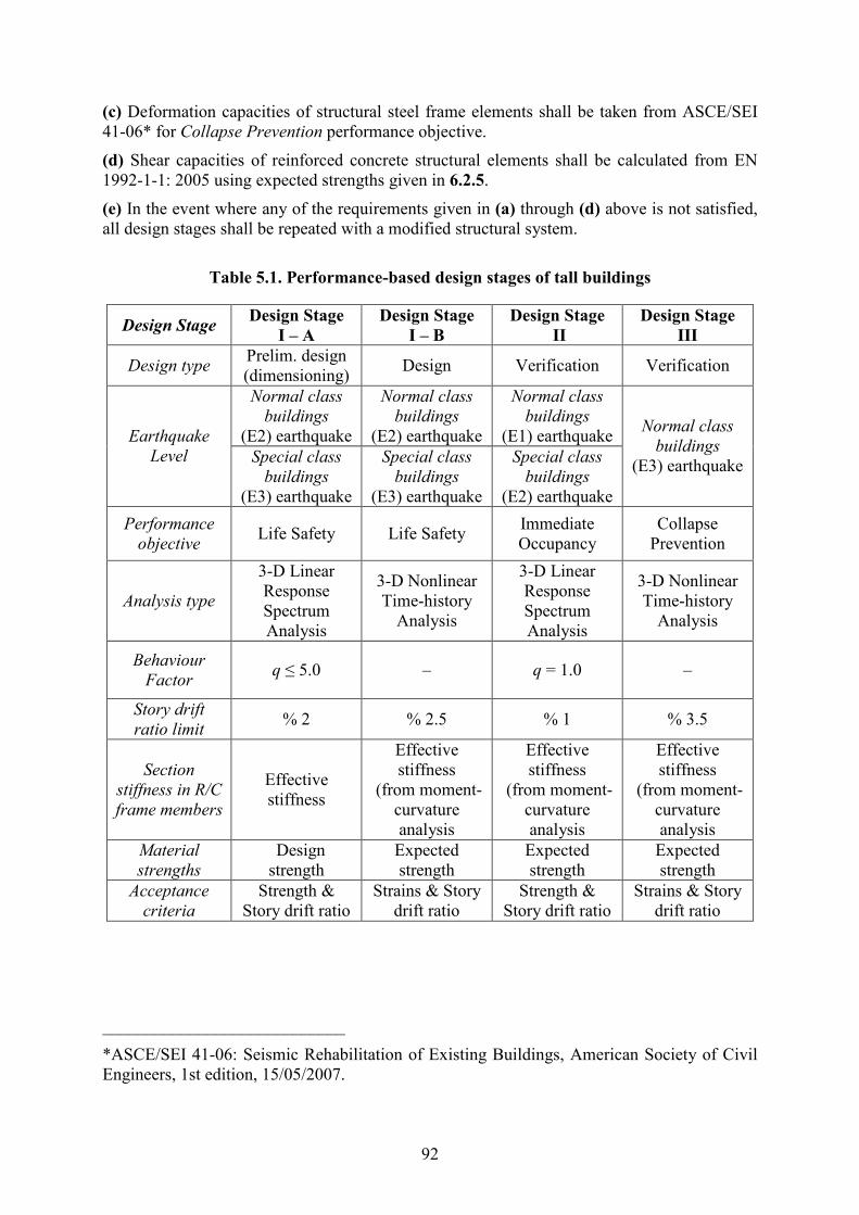
92
(c) Deformation capacities of structural steel frame elements shall be taken from ASCE/SEI
41-06* for Collapse Prevention performance objective.
(d) Shear capacities of reinforced concrete structural elements shall be calculated from EN
1992-1-1: 2005 using expected strengths given in 6.2.5.
(e) In the event where any of the requirements given in (a) through (d) above is not satisfied,
all design stages shall be repeated with a modified structural system.
Table 5.1. Performance-based design stages of tall buildings
Design Stage Design Stage
I – A
Design Stage
I – B
Design Stage
II
Design Stage
III
Design type Prelim. design
(dimensioning) Design Verification Verification
ormal class
buildings
(E2) earthquake
ormal class
buildings
(E2) earthquake
ormal class
buildings
(E1) earthquake Earthquake
Level Special class
buildings
(E3) earthquake
Special class
buildings
(E3) earthquake
Special class
buildings
(E2) earthquake
ormal class
buildings
(E3) earthquake
Performance
objective Life Safety Life Safety
Immediate
Occupancy
Collapse
Prevention
Analysis type
3-D Linear
Response
Spectrum
Analysis
3-D Nonlinear
Time-history
Analysis
3-D Linear
Response
Spectrum
Analysis
3-D Nonlinear
Time-history
Analysis
Behaviour
Factor q ≤ 5.0 – q = 1.0 –
Story drift
ratio limit % 2 % 2.5 % 1 % 3.5
Section
stiffness in R/C
frame members
Effective
stiffness
Effective
stiffness
(from moment-
curvature
analysis
Effective
stiffness
(from moment-
curvature
analysis
Effective
stiffness
(from moment-
curvature
analysis
Material
strengths
Design
strength
Expected
strength
Expected
strength
Expected
strength
Acceptance
criteria
Strength &
Story drift ratio
Strains & Story
drift ratio
Strength &
Story drift ratio
Strains & Story
drift ratio
____________________________
*ASCE/SEI 41-06: Seismic Rehabilitation of Existing Buildings, American Society of Civil
Engineers, 1st edition, 15/05/2007.
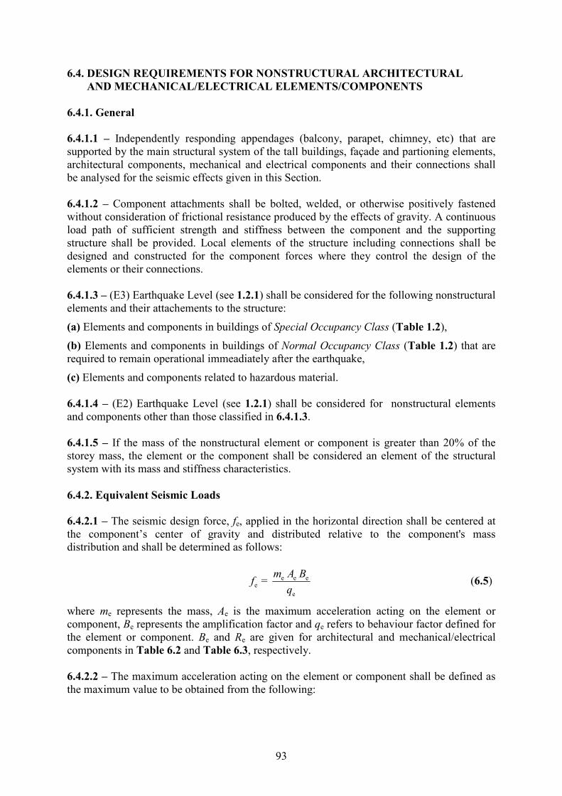
93
6.4. DESIG REQUIREMETS FOR OSTRUCTURAL ARCHITECTURAL
AD MECHAICAL/ELECTRICAL ELEMETS/COMPOETS
6.4.1. General
6.4.1.1 – Independently responding appendages (balcony, parapet, chimney, etc) that are
supported by the main structural system of the tall buildings, façade and partioning elements,
architectural components, mechanical and electrical components and their connections shall
be analysed for the seismic effects given in this Section.
6.4.1.2 – Component attachments shall be bolted, welded, or otherwise positively fastened
without consideration of frictional resistance produced by the effects of gravity. A continuous
load path of sufficient strength and stiffness between the component and the supporting
structure shall be provided. Local elements of the structure including connections shall be
designed and constructed for the component forces where they control the design of the
elements or their connections.
6.4.1.3 – (E3) Earthquake Level (see 1.2.1) shall be considered for the following nonstructural
elements and their attachements to the structure:
(a) Elements and components in buildings of Special Occupancy Class (Table 1.2),
(b) Elements and components in buildings of ormal Occupancy Class (Table 1.2) that are
required to remain operational immeadiately after the earthquake,
(c) Elements and components related to hazardous material.
6.4.1.4 – (E2) Earthquake Level (see 1.2.1) shall be considered for nonstructural elements
and components other than those classified in 6.4.1.3.
6.4.1.5 – If the mass of the nonstructural element or component is greater than 20% of the
storey mass, the element or the component shall be considered an element of the structural
system with its mass and stiffness characteristics.
6.4.2. Equivalent Seismic Loads
6.4.2.1 – The seismic design force, fe, applied in the horizontal direction shall be centered at
the component’s center of gravity and distributed relative to the component's mass
distribution and shall be determined as follows:
e e ee
e
= m A B
fq
(6.5)
where me represents the mass, Ae is the maximum acceleration acting on the element or
component, Be represents the amplification factor and qe refers to behaviour factor defined for
the element or component. Be and Re are given for architectural and mechanical/electrical
components in Table 6.2 and Table 6.3, respectively.
6.4.2.2 – The maximum acceleration acting on the element or component shall be defined as
the maximum value to be obtained from the following:

94
(a) Maximum value of average total accelerations obtained from nonlinear analysis at Stage
I-B for ormal Occupancy Class buildings and at Stage III for Special Occupancy Class
buildings may be defined as Ae .
(b) In particular cases where mass and stiffness characteristics of component or its
attachement is required to be considered, Ae may be calculated as a spectral acceleration
corresponding to natural period, Te , of the component from the floor spectrum obtained
through the analysis in (b). natural period, Te , may be calculated from;
ee
e
= 2m
Tk
π (6.6)
where ke represents the effective stiffness coefficient of the nonstructural element or
component. In this case, amplification factor defined in Eq.(6.5) shall be taken as Be = 1.
6.4.2.3 – Equivalent seismic load calculated with Eq.(6.5) shall not be less than the minimum
load defined below:
e e SDmin = 0.3f m S (6.7)
6.4.2.4 – Equivalent seismic load given in Eq.(6.5) shall be applied independently in both
horizontal earthquake directions in combination with the dead load, service loads of the
element or component plus a vertical seismic load equal to e SD0.2m S±
6.4.2.5 – For elements or components suspended from the structural system (with chains,
cables, etc), a seismic load equal to 1.4 times the weight of the element or component shall be
applied simultaneously in both horizontal and vertical directions.
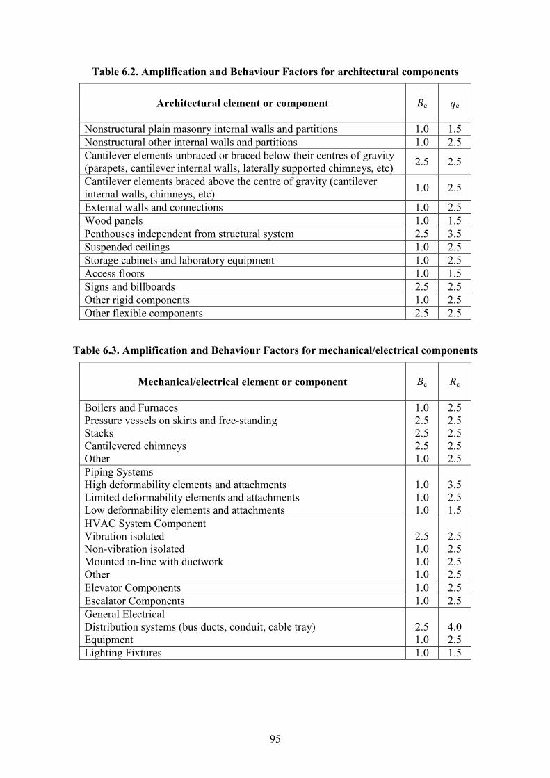
95
Table 6.2. Amplification and Behaviour Factors for architectural components
Architectural element or component
Be qe
Nonstructural plain masonry internal walls and partitions 1.0 1.5
Nonstructural other internal walls and partitions 1.0 2.5
Cantilever elements unbraced or braced below their centres of gravity
(parapets, cantilever internal walls, laterally supported chimneys, etc) 2.5 2.5
Cantilever elements braced above the centre of gravity (cantilever
internal walls, chimneys, etc) 1.0 2.5
External walls and connections 1.0 2.5
Wood panels 1.0 1.5
Penthouses independent from structural system 2.5 3.5
Suspended ceilings 1.0 2.5
Storage cabinets and laboratory equipment 1.0 2.5
Access floors 1.0 1.5
Signs and billboards 2.5 2.5
Other rigid components 1.0 2.5
Other flexible components 2.5 2.5
Table 6.3. Amplification and Behaviour Factors for mechanical/electrical components
Mechanical/electrical element or component
Be Re
Boilers and Furnaces
Pressure vessels on skirts and free-standing
Stacks
Cantilevered chimneys
Other
1.0
2.5
2.5
2.5
1.0
2.5
2.5
2.5
2.5
2.5
Piping Systems
High deformability elements and attachments
Limited deformability elements and attachments
Low deformability elements and attachments
1.0
1.0
1.0
3.5
2.5
1.5
HVAC System Component
Vibration isolated
Non-vibration isolated
Mounted in-line with ductwork
Other
2.5
1.0
1.0
1.0
2.5
2.5
2.5
2.5
Elevator Components 1.0 2.5
Escalator Components 1.0 2.5
General Electrical
Distribution systems (bus ducts, conduit, cable tray)
Equipment
2.5
1.0
4.0
2.5
Lighting Fixtures 1.0 1.5
96
6.4.3. Limitation of displacements
6.4.3.1 – In cases where nonstructural elements or components are attached to two different
points of the same structure experiencing different displacements, or attached to two different
structural systems, the effects of relative displacements between the points of attachement
shall be considered. Relative displacements shall be calculated from the results of nonlinear
analysis of the structural system at Design Stage I-B for ormal Occupancy Class buildings
(see 6.3.2) or at Design Stage III for Special Occupancy Class buildings (see 6.3.4).
6.4.3.2 – Relative displacements of nonstructural elements or components, δe , shall not be
more than the value given in Eq.(6.8).
i maxe x y
i
(δ )δ ( )h h
h≤ − (6.8)
where hx and hy represent the vertical distances of top and bottom attachement points,
respectively, of the nonstructural element or component measured from the relevant floor
level. (δi)max / hi is the allowable storey drift ratio specified in 6.3.2 for ormal Occupancy
Class buildings and in 6.3.4 for Special Occupancy Class buildings.
6.4.3.3 – Relative displacements of nonstructural elements or components attached to two
different structural systems shall be calculated as the absolute sum of the maximum relative
displacements at points of attachement and it shall not be more than the value given in
Eq.(6.9).
iA max iB maxe x y
iA iB
(δ ) (δ )δ + h h
h h≤ (6.9)
where (δiA)max / hiA ve (δiB)max / hiB represent the allowable storey drift ratios of the first and
second structural systems, respectively, specified in 6.3.2 for ormal Occupancy Class
buildings and in 6.3.4 for Special Occupancy Class buildings.
6.4.4. onstructural façade elements and connections
Glass or curtain wall façade elements of tall buildings shall be subjected to static and dynamic
tests described in the following standards:
(a) “Recommended Static Test Method for Evaluating Curtain Wall and Storefront Systems
Subjected to Seismic and Wind Induced Story Drifts”, AAMA 501.4-00, American
Architectural Manufacturing Association, Schaumburg, Illinois, 2001.
(b) “Recommended Dynamic Test Method for Determining the Seismic Drift Causing Glass
Fallout from a Wall System”, AAMA 501.6-01, American Architectural Manufacturing
Association, Schaumburg, Illinois, 2001.
6.5. IDEPEDET DESIG REVIEW
Design of tall buildings according to this Code shall be peer reviewed and endorsed by
independent reviewers in all design stages, starting from the structural system inception stage.
The administrative structure of the independent design review process will be established by
Dubai Municipality.

97
CHAPTER 7
STRUCTURAL HEALTH MOITORIG SYSTEMS
FOR TALL BUILDIGS
Health monitoring systems shall be established in all tall buildings in order to monitor the real
behaviour of tall building structural systems, to improve the existing seismic and wind codes
and to predict the level of seismic damage in a tall building immediately after the ocurrence of
an earthquake. A typical health monitoring system shall have a minimum 8 acceleration
sensors distributed in the building, as shown in Fig.7.1.
(a) Acceleration sensors shall be syncronized and connected to a 24-bit digital recording
system equipped with a GPS card. Recording system shall record the building vibrations
continuously and transfer the data in real time to a prescribed centre via internet, modem or
similar channels. Sufficient battery and disk capacity shall be provided against electricity and
communication shortages, which will help the system operate and store data for at least a
period of one week.
(b) Technical specification of sensors and recording systems shall be provided by Dubai
Municipality.
(c) Vibration records shall be transferred in real time to the Structural Health Monitoring
Centre of Dubai Municipality. The records shall be stored at this centre as well as by the
building owner.
Figure 7.1
Record box
(at any storey)
Horizontal sensors
Vertical sensors

98
AEX A
SOIL CLASSIFICATIO FOR
SPECIFICATIO OF SEISMIC GROUD MOTIO
A.1. Soil classification procedure
A.1.1 – For the purpose of specifying elastic response spectrum, the site soil shall be
classified according to Table A.1. Where the soil properties given in Table A.1 are not
known in sufficient detail to determine the soil class, it shall be permitted to assume Soil
Class D unless Dubai Municipality determines that Soil Class E or F could apply at the site or
in the event that Site Class E or F is established by geotechnical data.
Table A.1. Soil classification parameters
Soil Class sv (m/s) ch or us (kPa)
A. Hard rock > 1500 NA NA
B. Rock 760 – 1500 NA NA
C. Very dense soil and soft rock 360 – 760 > 50 100
D. Stiff soil 180 – 360 15 – 50 50 – 100
< 180 < 15 < 50 E. Soft clay soil
or any profile with more than 3 m of soil with
Plasticity index: PI > 20
Moisture content: w ≥ 40%
Undrained shear strength: us < 25 kPa
F. Soils requiring site response
analysis
1. Soils vulnerable to potential failure or collapse
under seismic loading such as liquefiable soils,
quick and highly sensitive clays, collapsible
weakly cemented soils
2. Peat and/or highly organic clays with more
than 3 m.
3. Very high plasticity clays with more than 7.5 m
and PI > 75
4. Very thick, soft/medium stiff clays with more
than 35 m and su < 50 kPa
A.1.2 – The parameters used in Table A.1 to define the Soil Class are based on the upper 30
m of the site profile. Profiles containing distinctly different soil and rock layers shall be
subdivided into those layers designated by a number that ranges from 1 to n at the bottom
where there are a total of n distinct layers in the upper 30 m. The symbol i then refers to any
one of the layers between 1 and n. Parameters characterizing upper 30 m is defined as
follows:
(a)
n
i
i = 1s n
i
i = 1 si
d
vd
v
=∑
∑ (A.1)
where vsi = shear wave velocity in m/s

99
di = thickness of any layer (between 0 and 30 m). n
i
i = 1
d∑ is equal to 30 m.
(b)
n
i
i = 1
ni
i = 1 i
d
d
=∑
∑ (A.2)
where i = Standard Penetration Resistance as directly, measured in the field without
corrections, and shall not be taken greater than 100 blows/ft. Where refusal is met for a rock
layer, i shall be taken as 100 blows/ft. i and di in Eq.(A.2) are for cohesionless soil,
cohesive soil and rock layers.
(c) sch m
i
i = 1 i
d
d
=
∑ (A.3)
where i and di in Eq.(A.3) are for cohesionless soil layers only.
ds = total thickness of cohesionless soil layers in the top 30 m. m
i s
i = 1
d d=∑
(d) cu k
i
i = 1 ui
ds
d
s
=
∑ (A.4)
where sui = undrained shear strength in kPa, and shall not be taken greater than 250 kPa.
dc = total thickness of cohesive soil layers in the top 30 m. k
i c
i = 1
d d=∑
A.2. Steps for classifying Soil Classes C,D,E,F
Step 1: Check for the four categories of Soil Class F (see Table A.1) requiring site-specific
evaluation. If the site corresponds to any of these categories, classify the site as Soil Class F
and conduct a site-specific evaluation.
Step 2: Check for the existence of a total thickness of soft clay > 3 m where a soft clay layer
is defined by su < 25 kPa, w ≥ 40% and PI > 20. If these criteria are satisfied, classify the site
as Soil Class E.
Step 3: Categorize the site using one of the following three methods with sv , and us
computed in all cases as specified in A.1.2:
(a) sv for the top 30 m ( sv method)
(b) for the top 30 m ( method)
(c) ch for cohesionless soil layers (PI < 20) in the top 30 m and average us for cohesive soil
layers (PI > 20) in the top 30 m ( us method)

100
If us method is used and, ch and us criteria differ, the category with the softer soils shall be
selected (for example, use Soil Class E instead of D).
A.3. Classifying Soil Classes A,B
A.3.1 – Assignment of Soil Class B shall be based on the shear wave velocity for rock. For
competent rock with moderate fracturing and weathering, estimation of this shear wave
velocity shall be permitted. For more highly fractured and weathered rock, the shear wave
velocity shall be directly measured or the site shall be assigned to Soil Class C.
A.3.2 – Assignment of Soil Class A shall be supported by either shear wave velocity
measurements on site or shear wave velocity measurements on profiles of the same rock type
in the same formation with an equal or greater degree of weathering and fracturing. Where
hard rock conditions are known to be continuous to a depth of 30 m, surficial shear wave
velocity measurements may be extrapolated to assess sv .
A.3.3 – Soil Classes A and B shall not be used where there is more than 3 m of soil between
the rock surface and the bottom of the spread footing or mat foundation.