Seismic and Wind Load Curbs EMPLOYEE OWNED -...
13
54 years of excellence... www.thybar.com 22 EMPLOYEE OWNED TM Seismic and Wind Load Curbs
Transcript of Seismic and Wind Load Curbs EMPLOYEE OWNED -...

54 years of excellence... www.thybar.com 22
EMPLOYEE OWNED
TM
Seismic and Wind Load Curbs

54 years of excellence... www.thybar.com 23
EMPLOYEE OWNED
TM
Seismic and Wind Load Curbs
Table of Content
General Information 24
Load Compliance Information 25-30
Flow Chart 31
Questionnaire 32-33

54 years of excellence... www.thybar.com 24
EMPLOYEE OWNED
TM
Seismic and Wind Load Curbs
Seismic and Wind Load Curbs Thybar has a complete line of laser cut, competitively priced, Wind Load and Seismic roof curbs. Advanced laser technology offers a superior weld with the highest tolerances available. Severe wind loads or seismic activity occurs in many areas in the U.S.. Thybar seismic curbs for rooftop HVAC units are specifically designed to withstand these forces. Each curb is manufactured to the Seismic and Wind Load design criteria required by geographic location.
Seismic Wind Load Vibro-Curbs Seismic Vibro-Curbs combine adjustable spring isolators and a roof curb into a single unit. Rooftop units can be set immediately after curb installation with roofing completed later without disturbing the unit. Flexible 9” flashing permits easy access to adjust isolators. Can be fabricated to match roof pitch. Duct attachment channels and/or airtight plenum available. Vibro-Curb can ship in one piece or knocked down.

54 years of excellence... www.thybar.com 25
EMPLOYEE OWNED
TM
Roof Equipment Support Design
For compliance with building code seismic and wind load requirements
Paul Selman is a licensed Professional Engineer (P.E.) in all 50 states. He has broad ex-perience in a variety of industries including manufacturing, transportation, power and HVAC system design. As an employee of Thybar Corporation, Paul is involved in the design and manufacture of custom sheet metal products to ensure compliance with wind load and seismic building code requirements. He can be reached by phone at the Thybar Corporation Main Plant & Office 800-666-CURB (2872) or by email at [email protected].
Table of Content
Introduction 26
Building Codes 27
International Building Code (IBC) 27
Seismic Design Force Calculation 28
Wind Load Design Force Calculation 29
Uniform Building Code (UBC) 29
Static Analysis 30
Flow Chart 31
Questionnaire 32-33
About the Author

54 years of excellence... www.thybar.com 26
EMPLOYEE OWNED
TM
Roof Equipment Support Design
For compliance with building code seismic and wind load requirements.
Introduction
This design guideline was prepared by Thybar Corporation using previously published information from the Vibration Isolation and Seismic Control Manufacturers Association (VISCMA), the International Code Council (ICC), the American Society of Heating, Refrigerating and Air-Conditioning Engineers, Inc. (ASHRAE) and the American Society of Civil Engineers (ASCE). It has been published to provide an overview of the process by which rooftop equipment supports and restraints are designed and to give an explanation of the information required in the design process.
The process by which rooftop equipment supports and restraints are designed can be summarized in three steps. This information is shown in flow chart format to provide an overview of the process, and a detailed questionnaire is attached. The questionnaire can be used to gather the information necessary for a licensed Professional Engineer (P.E.) to certify that the rooftop equipment supports and restraints meet the requirements of the applicable building code.
1) Determine the governing building code for the particular project.
This information is typically provided in the Mechanical or Structural sections of the project specifications. The designer should also be aware of any project requirements that are more stringent than those listed in the building code.
If the customer is not familiar with the project specs, the support and restraint designer must identify the name and latest revision of the governing building code using available research or previous experience. Building code requirements will be discussed in later sections of this guideline.
2) Determine the seismic/wind load design force that the rooftop equipment and
equipment support assembly is required to withstand.
The building codes commonly adopted in the US provide step-by-step procedures for determining the design force that a rooftop assembly will be required to withstand. This design force may be a result of seismic activity or wind load, depending on the project location. In areas of the US where it is not intuitively clear which load is greater, the designer should perform both calculations and design the supports and restraints accordingly.
3) Determine the requirement for attachment of rooftop equipment to equipment
support and equipment support to building roof.
Once the design load on the rooftop equipment is calculated, the designer uses static analysis to ensure that this load is safely transmitted through the equipment base into the equipment support. The method of attachment between the roof top equipment and the equipment support must be sufficient to keep the equipment in place while resisting the tension, shear, moment and uplift forces generated by the design force acting on the rooftop equipment. The equipment support must be designed and manufactured with the ability to safely transfer these forces into the building structure.
The designer must ensure that the project Mechanical or Structural engineer is aware of the loads that will be imposed on the building structure by the rooftop equipment.

54 years of excellence... www.thybar.com 27
EMPLOYEE OWNED
TM
Roof Equipment Support Design
For compliance with building code seismic and wind load requirements.
Building Codes
The primary purpose of seismic and wind load related building codes is to provide a uniform method to determine the seismic and wind induced forces for any location. The forces must be determined with enough accuracy to ensure a safe and economical design. Different
regions of the United States have adopted standard codes and modified applicable portions of model codes to fit their particular needs. The following is a discussion of the International Building Code and the Uniform Building Code as they apply to determining the design force.
International Building Code (IBC)
The IBC was originally prepared in 1997 by five drafting subcommittees appointed by the
International Code Council (ICC) and consisting of representatives of Building Officials and Code Administrators International, Inc. (BOCA), International Conference of Building Officials (ICBO) and Southern Building Code Congress International (SBCCI). The intent was to draft a comprehensive set of regulations for building systems consistent with and inclusive of the scope of the existing model codes.
The IBC is available for adoption and use by jurisdictions in the United States and
internationally. 47 states and the District of Columbia have currently adopted the IBC as their governing building code. Because the IBC is emerging as the dominant code for seismic and wind load design issues, a detailed explanation of design force determination is provided below.

54 years of excellence... www.thybar.com 28
EMPLOYEE OWNED
TM
Seismic Design Force Calculation
IBC 2003 Section 1615 provides design specifications for determining earthquake design site ground motion. Section 1621.1 refers to ASCE 7 “Minimum Design Loads
for Buildings and other Structures” for the seismic design force (Fp) on
Mechanical Components and Systems. Fp is the force centered at the component's center of gravity and distributed relative to the component's mass
distribution. Fp is determined according to the following equation:
While the full details of all the variables used in this formula are beyond the scope of this guideline, four key pieces of information are required to complete the design
of rooftop equipment supports and restraints:
1) SS is the short period Maximum Considered Earthquake (MCE) acceleration at the project site. This information typically comes from identifying the project location on a map to determine the project specific MCE acceleration.
2) Fa is the site coefficient, and it depends on the Site Class and SS. Site Class is determined using the project site soil profile and average properties in the top 100 feet of soil. Where project specific soil properties are unknown, the IBC allows Site Class “D” to be used.
3) Wp is the mechanical component operating weight, as provided by the equipment manufacturer.
Sa
P
P
PPP SF
h
z
I
R
WaF
3
221
4.0
Roof Equipment Support Design
For compliance with building code seismic and wind load requirements.
Seismic Design Force Calculation

54 years of excellence... www.thybar.com 29
EMPLOYEE OWNED
TM
4) Ip is the component importance factor and is determined by the nature of the building occupancy. The designer must know the final use of the building to determine the Importance factor. The IP will be different for a building that represent a low hazard or a substantial hazard to human life in the event of failure, or if the structure is designated as an essential facility such as a hospital or an earthquake shelter.
Wind Load Design Force Calculation
IBC 2003 Section 1609 requires that wind loads on every building or structure be determined in accordance with Section 6 of ASCE 7. The design wind force on rooftop equipment is calculated
according to ASCE 7 Section 6.5.15. The equation for the wind load design force (FW) is as follows:
Where:
Reducing these equations to the key pieces of information that the designer must have leads to the following items:
1) Cf is the force coefficient. It depends on the height and width of the rooftop equipment, as provided by the equipment manufacturer.
2) Kz is the velocity pressure coefficient. It depends on building height and exposure category. The exposure category depends on the landscape around the building, and varies for urban, wooded areas or bodies of water nearby.
3) Kzt is the topographic factor. It depends on the geography of the surrounding area and accounts for wind speed changes at hills, ridges and escarpments.
4) V is the design wind speed, in miles per hour. It depends on the project location and it comes from identifying the project location on a map.
5) I is the importance factor, depending on project occupancy category and design wind speed. As discussed previously, the designer must know the final use of the building in order to determine the importance factor.
Uniform Building Code (UBC)
The Uniform Building Code (UBC) was first issued in 1927 by the International Conference of Building Officials (ICBO), and has been the most widely used of the building codes in North America. The UBC classifies earthquake hazard on a scale from 0 (least hazard) to 4 (most hazard). This is the “seismic zone” terminology that many people are familiar with. These values are used to determine the strengths of various components of a building required to resist earthquake damage. 1999 is the latest version of the UBC, and it specifies a design lateral force (Fp) for nonstructural components as follows:
ffzW AGCqF
IVKKKq dztzz
200256.0
P
r
x
P
PaPP W
h
h
R
ICaF
31
Roof Equipment Support Design
For compliance with building code seismic and wind load requirements.

54 years of excellence... www.thybar.com 30
EMPLOYEE OWNED
TM
Roof Equipment Support Design
For compliance with building code seismic and wind load requirements.
Once the design load is determined by any of the above methods, static analysis assumes that the equipment does not move during the earthquake or high wind speeds. In order for this to be true, the forces generated by the difference in accelerations between the equipment center of gravity and the building roof must be balanced by reactions at the equipment supports and restraints. The sum of the forces and moments generated between the equipment and the equipment support, as well as between the equipment support and the building structure, must be zero. A typical free body diagram of the static analysis is shown in Figure 1.
The static analysis is to be performed by a licensed Professional Engineer (P.E.) using sound engineering principals and industry accepted safety factors. Detailed drawings of the equipment support and the equipment restraint are to be used with the known material properties and shape factors to verify that allowable stress values are not exceeded in the supports, restraints or attachment hardware.
The four key pieces of information required completing the design of rooftop equipment supports and restraints according to UBC 1999 are:
1) The seismic zone is determined by identifying the project location on a UBC map.
2) Soil profile type. Where project specific soil properties are unknown, the UBC allows type “SD” to be used.
3) Wp is the mechanical component operating weight, as provided by the equipment manufacturer.
4) Ip is the component importance factor and is determined by the nature of the building occupancy. As previously discussed, the designer must know the final use of the building to determine the importance factor.
Static Analysis

54 years of excellence... www.thybar.com 31
EMPLOYEE OWNED
TM
Roof Equipment Support Design
For compliance with building code seismic and wind load requirements.

54 years of excellence... www.thybar.com 32
EMPLOYEE OWNED
TM
Roof Equipment Support Design
For compliance with building code seismic and wind load requirements.
Seismic/Wind Load Questionnaire
1) Project Data a) What is the project name? ____________________________________ b) What is the project location? ____________________________________ City State Zip c) What is the applicable building code for this project? (This information may be found in the Structural or Mechanical portion of the project specifications or bid documents.) _________International Building Code (IBC) ________2003 ________2006 ________2009 ________2012 _________California Building Code (CBC) ________2001 ________2007 ________2010 ________Other:__________________ ________Unknown d) Are there any wind or seismic design criteria in the project specifications that exceed the applicable code requirements? Yes_________ No________ i) If so, what are they?_______________________________ e) Has there been any soil analysis conducted for this project site? Yes______ No_______ i) If so, what is the site class?_________________________ (If no soil analysis is available, default site class is "D") f) Describe the building usage by choosing one of the four categories below: (Occupancy Category) _________i) A building that does not fit into categories ii, iii or iv below. (II) _________ii) Does the building represent a substantial hazard to human life in the event of failure including, but not limited to: (III) Buildings and other structures where more than 300 people congregate in one area. Buildings and other structures with elementary school, secondary school or day-care facilities with capacity greater than 250. Buildings and other structures with a capacity greater than 500 for colleges or adult education facilities. Health care facilities with a capacity of 50 or more resident patients but not having surgery or emergency treatment facilities. Any other occupancy with an occupant load greater than 5,000. Power-generating stations, water treatment for potable water, waste water treatment facilities and other public utility facilities not included in category iii. Buildings and other structures not included in category iii containing sufficient quantities of toxic or explosive substances to be dangerous to the public if released.
54 years of excellence... www.thybar.com 33
EMPLOYEE OWNED
TM
Roof Equipment Support Design
For compliance with building code seismic and wind load requirements.
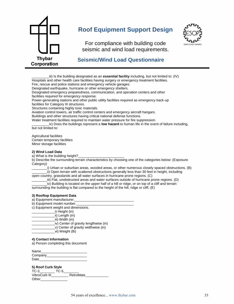
Seismic/Wind Load Questionnaire
_________iii) Is the building designated as an essential facility including, but not limited to: (IV) Hospitals and other health care facilities having surgery or emergency treatment facilities. Fire, rescue and police stations and emergency vehicle garages. Designated earthquake, hurricane or other emergency shelters. Designated emergency preparedness, communication, and operation centers and other facilities required for emergency response. Power-generating stations and other public utility facilities required as emergency back-up facilities for Category III structures. Structures containing highly toxic materials. Aviation control towers, air traffic control centers and emergency aircraft hangars. Buildings and other structures having critical national defense functions. Water treatment facilities required to maintain water pressure for fire suppression. _________iv) Does the buildings represent a low hazard to human life in the event of failure including, but not limited to: Agricultural facilities Certain temporary facilities Minor storage facilities 2) Wind Load Data a) What is the building height?________________________ b) Describe the surrounding terrain characteristics by choosing one of the categories below: (Exposure Category) ________i) Urban or suburban areas, wooded areas, or other numerous closely spaced obstructions. (B) ________ii) Open terrain with scattered obstructions generally less than 30 feet in height, including open country, grasslands and all water surfaces in hurricane prone regions. (C) ________iii) Flat, unobstructed areas and water surfaces outside of hurricane prone regions. (D) ________iv) Building is located on the upper half of a hill or ridge, or on top of a cliff and terrain surrounding the building is flat compared to the height of the hill, ridge or cliff. (E) 3) Rooftop Equipment Data a) Equipment manufacturer._______________________________ b) Equipment model number.______________________________ c) Equipment weight and dimensions. ____________i) Height (in) ____________ii) Length (in) ____________iii) Width (in) ____________iv) Center of gravity lengthwise (in) ____________v) Center of gravity widthwise (in) ____________vi) Weight (lb) 4) Contact Information a) Person completing this document Name________________________ Company_____________________ Date_________________________ 5) Roof Curb Style TC-3________ TC-5________ VibroCurb III_________ RetroMate____________ Other______________

54 years of excellence... www.thybar.com 148
EMPLOYEE OWNED
TM
Addison Corporate Office 913 S. Kay Avenue Addison, IL 60101 Ph: (630) 543-5300 Fax: (630) 543-5309 800-666-CURB (2872)
Farmers Branch Office 13801 Senlac Drive Farmers Branch, TX 75234 Ph: (972) 416-6220 Fax: (972) 418-6713 800-777-CURB (2872)
Akron Office
Burt Manufacturing Co. 44 E. South Street Akron, OH 44311 Ph: (330) 762-0061 Fax: (330) 762-0914 800-837-CURB (2872)
Louisville Office
10200 Bunsen Way Louisville, KY 40299 Ph: (502) 499-5480 Fax: (502) 499-5481 800-993-CURB (2872)
McCarran Office
711 Denmark Drive McCarran, NV 89434 Ph: (775) 343-0600 Fax: (775) 343-0606 866-917-CURB (2872)
Vibro-MateTM