SEE ATTACHED FOR / CONDITIONS OF...
74
Form 3160-3 <^ h 2 0 l 2 ) OCD Artesia UNITED STATES _ DEPARTMENT OF THE INTERIOR , .-. BUREAU OF LAND MANAGEMENT K^Sr'V^ APPLICATION FOR PERMIT TO DRILL.OR REENTER FORM APPROVED OMB No. 1004-0137 Expires October 31,2014 Form 3160-3 <^ h 2 0 l 2 ) OCD Artesia UNITED STATES _ DEPARTMENT OF THE INTERIOR , .-. BUREAU OF LAND MANAGEMENT K^Sr'V^ APPLICATION FOR PERMIT TO DRILL.OR REENTER 5. Lease Serial No. NMNM113941, NMNM113942 Form 3160-3 <^ h 2 0 l 2 ) OCD Artesia UNITED STATES _ DEPARTMENT OF THE INTERIOR , .-. BUREAU OF LAND MANAGEMENT K^Sr'V^ APPLICATION FOR PERMIT TO DRILL.OR REENTER 6. If Indian, Allotee or Tribe Name la. Type of work: .[/]l);<ll.l . -. • • LJ REENTER • lb. Type of Well: [/] Oil Well | | Gas Well | |Other f/| Single Zone [ | Multiple Zone n: If Unit or CA Agreement,"Name arid No. la. Type of work: .[/]l);<ll.l . -. • • LJ REENTER • lb. Type of Well: [/] Oil Well | | Gas Well | |Other f/| Single Zone [ | Multiple Zone 8. Lease Name and Well No.'* " , J " Skeen 22 26 26 Federal #7H 2. Name pf Operator CHEVRON U.S.A. INC. • 9. API Well No. , _ 3a. A'ddress 1 5 SMITH ROAD . MIDLAND, TEXAS.,79705 ........ 3b. Phone No. (include area code) ' i0. Field and-Pool, of Exploratory * 4. Location of Well (Report location clearly and in accordance with art}'Stale requirements.*) At surface 402' FSL, & 660' FEL, UL: P At proposed prod.zone 2310' FSL, & 660' FEL,' UL: I ' ' 11. Sec, T. R. M. or.BIk.and Survey or Area SEC 22, T26S, R26E, (SHL) SEC 15, T26S, R26E, (BHL) < 14. Distance in miles arid direction from nearest town or post office* 24 MILES FROM MALAGA, NEW MEXICO ' 12. County or Parish 13. State EDDY NM* is Distance from proposed* . n ~ , r-oi n r 0 r r - - n locaiion 6 nearest 4 0 2 F S L O F S E C 2 2 property or lease line, ft. (Also to nearest drig. unit line, if any) 16 No. of acres in lease 3040 " - 17: Spacing Unit dedicated to this well 240 18. Distance from proposed location*. 7039' to Cimarex ^ t S ^ T ^ J«mpmo Spring 16 S 1 19, Proposed Depth,. _ t , : MD- 16,500' PILOT HOLE- TVD- 11,500' <$^%0' 20, BLM/BIA .Bond No. on file •. • CA0329 21. Elevations (Show whether DF, KDB, RT, GL, etc.) 3406' GL 21 Approximate aarc work will start* 23. Estimated duration 24. Attachments The following, completed in accordance with the requirements of Onshore Oil and Gas Order No. 1, must be attached to this form: 1. Well plat certified by a registered surveyor. 2. A Drilling Plan. : 3. A Surface Use Plan (if the location is on National Forest System Lands, the SUPO'must be filed with the' appropnatc^ofest Service Office). 4. Bond to cover the operations unless covered by an existing bond on file (see Item 20 above). 5. Operator certification '6. • 'Such'other site'specific information and/or plans as may be required by the ' BLM. ,,. K. '. • - ... ,.. . "' .'• .'. 25. S ^ ^ ^ ^ Name (Printetl'Typed)"- DENISE PINKERTON ; Date' ' 05/30/2014 • Title REGULATORY SPECIALIST Approved by (Signatutefc Name (Printecl'Typed)' te 19 20H Title FIELD MANAGER' Office CARLSBAD FIELD OFFICE Appl icatipn approval does not warrant or certify that the applicant holds legal or equitable title to those rights in the subject lease which "would entitle the applicant to ' cond'uct'bperalidns'tHeredn. Conditions of approval, if any, are attached. • APPROVAL FOR TWO YEAR.9 Title 18 U.S.C. Section 1001 and Title 43 U.S.C. Section 1212, make it a crime for any person knowingly and willfully to make to any departrnent .or agency of the United. States any false, fictitious or fraudulent statements or representations as to any matter within'its jurisdiction.- ' ' (Continued on page<2) Carlsbad Controlled Water Basi., *(Instructions on page 2.) OIL CONSERVATION ARTESIA DISTRICT DEC 3 0 2014 Approval Subject to General Requirements & Special Stipulations Attached RECEIVED SEE ATTACHED FOR / CONDITIONS OF APPROVAL
Transcript of SEE ATTACHED FOR / CONDITIONS OF...

Form 3160-3
< ^ h 2 0 l 2 ) OCD Artesia UNITED STATES _
DEPARTMENT OF THE INTERIOR , .-. BUREAU OF LAND MANAGEMENT K^Sr'V^
APPLICATION FOR PERMIT TO DRILL.OR REENTER
FORM APPROVED OMB No. 1004-0137
Expires October 31,2014
Form 3160-3
< ^ h 2 0 l 2 ) OCD Artesia UNITED STATES _
DEPARTMENT OF THE INTERIOR , .-. BUREAU OF LAND MANAGEMENT K^Sr'V^
APPLICATION FOR PERMIT TO DRILL.OR REENTER
5. Lease Serial No. NMNM113941, NMNM113942
Form 3160-3
< ^ h 2 0 l 2 ) OCD Artesia UNITED STATES _
DEPARTMENT OF THE INTERIOR , .-. BUREAU OF LAND MANAGEMENT K^Sr'V^
APPLICATION FOR PERMIT TO DRILL.OR REENTER 6. If Indian, Allotee or Tribe Name
la. Type of work: . [ / ] l ) ; < l l . l . -. • • L J REENTER •
lb. Type of Well: [ / ] Oil Well | | Gas Well | |Other f / | Single Zone [ | Multiple Zone
n: If Unit or CA Agreement,"Name arid No. la. Type of work: . [ / ] l ) ; < l l . l . -. • • L J REENTER •
lb. Type of Well: [ / ] Oil Well | | Gas Well | |Other f / | Single Zone [ | Multiple Zone 8. Lease Name and Well No.'* " , J "
Skeen 22 26 26 Federal #7H
2. Name pf Operator CHEVRON U.S.A. INC. • 9. API Well No. , _
3a. A'ddress 1 5 SMITH ROAD
. MIDLAND, TEXAS.,79705 . . . . . . . .
3b. Phone No. (include area code) ' i0. Field and-Pool, of Exploratory *
4. Location of Well (Report location clearly and in accordance with art}'Stale requirements.*)
At surface 402' FSL, & 660' FEL, UL: P
At proposed prod.zone 2310' FSL, & 660' FEL,' UL: I ' '
11. Sec, T. R. M. or.BIk.and Survey or Area
SEC 22, T26S, R26E, (SHL) SEC 15, T26S, R26E, (BHL) <
14. Distance in miles arid direction from nearest town or post office* 24 MILES FROM MALAGA, NEW MEXICO '
12. County or Parish 13. State
EDDY NM*
is Distance from proposed* . n ~ , r-oi n r 0 r r - -n locaiion 6 nearest 4 0 2 F S L O F S E C 2 2
property or lease line, ft. (Also to nearest drig. unit line, if any)
16 No. of acres in lease 3040 " -
17: Spacing Unit dedicated to this well
240
18. Distance from proposed location*. 7039' to Cimarex
^ t S ^ T ^ J«mpmo Spring 16 S1
19, Proposed Depth,. _t , :
MD- 16,500' PILOT HOLE-TVD- 11,500' <$^%0'
20, BLM/BIA .Bond No. on file •. •
CA0329
21. Elevations (Show whether DF, KDB, RT, GL, etc.)
3406' GL
21 Approximate aarc work will start* 23. Estimated duration
24. Attachments
The following, completed in accordance with the requirements of Onshore Oil and Gas Order No. 1, must be attached to this form:
1. Well plat certified by a registered surveyor. 2. A Drilling Plan. :
3. A Surface Use Plan (if the location is on National Forest System Lands, the SUPO'must be filed with the' appropnatc^ofest Service Office).
4. Bond to cover the operations unless covered by an existing bond on file (see Item 20 above).
5. Operator certification '6. • 'Such'other site'specific information and/or plans as may be required by the '
BLM. ,,. K. '. • - . . . ,.. . " ' .'• .'.
25. S ^ ^ ^ ^ Name (Printetl'Typed)"-DENISE PINKERTON ;
Date' ' 05/30/2014 •
Title REGULATORY SPECIALIST
Approved by (Signatutefc Name (Printecl'Typed)' te 19 20H Title
FIELD MANAGER' Office
CARLSBAD FIELD OFFICE
Appl icatipn approval does not warrant or certify that the applicant holds legal or equitable title to those rights in the subject lease which "would entitle the applicant to ' cond'uct'bperalidns'tHeredn. Conditions of approval, if any, are attached. • APPROVAL FOR TWO YEAR.9 Title 18 U.S.C. Section 1001 and Title 43 U.S.C. Section 1212, make it a crime for any person knowingly and willfully to make to any departrnent .or agency of the United. States any false, fictitious or fraudulent statements or representations as to any matter within'its jurisdiction.- ' '
(Continued on page<2)
Carlsbad Controlled Water Basi.,
*(Instructions on page 2.)
OIL CONSERVATION ARTESIA DISTRICT
DEC 3 0 2014
Approval Subject to General Requirements & Special Stipulations Attached
RECEIVED
SEE ATTACHED FOR / CONDITIONS OF APPROVAL

CERTIFICATION
I hereby certify that I, or someope under my direct supervision, have inspected the drill site and access route proposed herein; that I am familiar with the conditions which currently exist; that I have full knowledge of state and Federal laws applicable to this operation; that the statements made in this APD package are, to the best of my knowledge, true and correct; and, that the work associated with the operations proposed will be performed in conformity with this APD package arid the terms and conditions under which it is approved. I also certify that I, or the company I represent, am responsible for the operations conducted under this application. These statements are subject to the provisions of 18 U.S^C. 1001 for the filing of a false statement.
Executed this 9,0 day of 'lYUl .20. It Name:
Kelry Wojtalj^k - Project Manager
Address: 1400 Smith Street, 40039 Houston, TX 77027
Office 713-372-9691
E-mail: [email protected]

E x h i b i t A l
District I 1625 N: French Dr.. Hobbs, N'M SS240
Pi!ciic:'l575) lOJ-f,161 Fm: (575) 3\>l-O720
Disthci.lt
S iT S.-First St. ArisSia. NMSS2J!)
l'horie: (5,75)743-1283 Fiv(575) 748:972,0
Di.srrid'UI
IGOO'KJO ( ta i l s ' P. rail. Ailcc. N.M K7-110
Phone:}50J)i.!. |-«|78 Fax; (j05) 33-1-6170
District !V
1220 S..SI: Francis Dr.. Ssr.Li Fe, N>! 57505
Piior.c; (505) 476-34o0 f:ax:.(505i -3 76^3462
S ta te pf 'New iVi ex ico Energy. Minerals. &. Natural 'Resources Department
OIL CONSERVATION DIVISION 1220 South St.\Francis Dr.
Santa Fe, NM 87505
WELL LOCATION. ANDACRHAGE. 1 )HpiC :AT TON PLAT
Fomi G-102 Revised August 1, 201 1
Submit one copy to appropriate District Office
• AMENDED REPORT
1 API Number 3 Pool Code
3 Property Ts;;ime ^
SK.EEN 22.26 26 EED.COM
' t Well-Number
7H
'OGRlD No. * Obcrntor Nunic
CHEVRON U:S.A. INC.
9 Elevation
.3406' ,0 Surface Location
UL or lot no.
P
Section
22
Township
26 SOUTH
Range
26 EAST, N.M.P.M.
Ldi I d ii Feet from the
402'
North/South line
SOUTH
Feet from the
, 6'60'
East/West line
EAST
County
EDDY 11 Bottom Hole Location If Different from Surface
UL or Utt no.
' I
Sect ion
15
Township
26 SOUTH
Range
26 EAST, N.M.P.M,
I.ol Idn Feet iVoin the
•23.10"
Nnrth/Somh line
SOUTH
Feci from the
• 660' _
Ea^t/West line
EAST
Comity
EDDY Dedicated Acres 1 1 Joint or InfiM
<^4b 1 4 Consolidation Code 1 5 Order No.
No allowable will be assigned to this completion until all interests have been consolidated or a non-standard unit has been approved by the division.
PROPOSED BOTTOM HOLE • LOCATION
X= ' '51.8,450 NAD 27
Y= 373,865
LAT. 32.041600
LONG: 104.273790
X= 559,633 MAD83
y= 373,921
LAT. 32.041721
LONG. 104.274286
SKEEN 22 26 26 FED COM M0.7H -. WELL
• 518,473
Y= 371.601
LAT. 32.021331
LONG. 104.273727
X= ' "559,657
Y= 374-658
LAT. 32.021753
LONG, 104.274222
NAQ33
ELEVATION'iMOffNAVD.M
-1.5- / v r t f t t
" O PE RATpR.C LRU I I CATION / Iwix'hy certify thai Ike ii:Jh>nuition conmi'it'd hcndit is tmc and complete
to the hiwt tifmy kaowktlgc- andIvlicf. undthai tkivc^ii'itutii/ii filler
owns a vitJ'^JiJ^'/i/e.-es/^ in the lend inr-fading
ihi/ (Hvpu^-d bt.ilt(i:n hois lucutkir. or has a light to drill /-'iii ui.thi>
hxniinit pursuant tn a coniruct'-w'ih an owru-rofsiii-.h a mi'm'ra! or
irt.:rking iih'fv.\f* or hi n \xAtutfuty pwtirig ugretwic'tu or u iVinpuIsvry
vdhvdw l-poling order hcytfajoi
Jiyiwiuic ,. ijaic
Printed iN'aiiie
X-niaii:Atkiress
' "SURVEYOR CERTIFICATION / hereby certify thai the well locatiun shown'on this
plat was plotted from field notes of acuta! surveys
made by me or under i>ry supervision, and ihat the
same is true and correct to the. best df-mv belief.
Chevron
DURING THE DRILLING OF THIS WELL, CHEVRON PROPOSES TO USE A CLOSED LOOP SYSTEM WITH A STEEL TANK AND HAUL TO THE REQUIRED DISPOSAL, PER THE OCD RULE 19.15.17.
CHEVRON USA INC HAS AN AGREEMENT WITH CEHMM TO PROVIDE THE NEPA INFORMATION TO BLM.
PLEASE FIND THE FOLLOWING ATTACHMENTS:
APDFORM PRIVATE SURFACE OWNER AGREEMENT (IF APPLICABLE) C102 (EXHIBIT A-l) VICINITY MAPS (EXHIBIT A-2 through MILE RADIUS MAP (EXHIBIT B) DRILLING PLAN DIRECTIONAL PLAN AND PLOT BOP SCHEMATIC CHOKE MANIFOLD SCHEMATIC BOPE TESTING RIG LAYOUT/FACILITY PAD (EXHIBIT D) ? , MISCELLANOUS SCHEMATICS C ^ r r ^ Cr-// (5 ? / / T . - .
SURFACE USE PLAN COFLEX HOSE TEST CERTIFICATION AND CHART WELLHEAD SCHEMATIC OIL AND GAS MEASUREMENT SCHEMATIC (EXHIBIT C) MISCELLANEOUS MAPS (PROPOSED PAD AND ACCESSS ROAD, EXISTING & PROPOSED ROW EASEMENT DETAIL, PROPOSED FLOWLINE) PRESSURE CONTROL WELLHEAD EQUIPMENT RUNNING PROCEDURE- IF REQUIRED OPERATOR CERTIFICATION - SIGNED
AT BLM , ON
H2S PLAN
ARCH SURVEY
"sKEEfi 3i-26-2S FED COM no. TH WELL
fr S18.473 WAD 27
V» 371,601
LAT- 32.D21G31
LQfJG. 104 2T3777 •
655.65? NADS3
371.6SB
32.021753
L0fJ5 HH2»222
ELEVATION - W W NAVO 83
WARCH. AREA CRN.
ELEVATION "333? ftAVD SS
ME ARCH-AREA. CRM.
£ 518.779 NA027 "5
SE ARCH. AREA CRN
ELEVATION -341TNMDS3 ELEVATION '341VNAVD33
SW ARCH. AHEA CRN.
ELEVATION *3397' 'JAVD E3
E x h i b i t A2 ElB/ATiON«J3S9'HAVDB8 ELE/A"nOf,'»J4(BNAVD83
PROPOSED ARCHAEOLOGICAL AREA
t i . 1 4 A e r o
ELEVATION - M tf f rJAVD 83
SE TOP S O I AREA CRN.
ELEVATION >3* I f f NA'JD 83
E L E V A T I O N *343r f w m a a .
SW TOP SOIL AREA CRTJ.
ELEVArarffj-norpyvoae
SESE
Sec. 22 Sursau o f Land M a n a g w & n t
(Proocsed Access ±0.15 A a s s . i 487 .74 ,
1 128 .34 Rods)
- EntargRm'To
- Eusia feat
FOR THE EXCLUSIVE USE OF
C H E V R O N U S A. INC.
(, WW. J .Den ia l III, Registered Professional
Land Surveyor, da hereby stale this plat i i true
Proposed Accets (1)Pointot Beginning
Skeen 22-25-21
Ho 7HWtt3
•-K--
Sea Exh ib i t " A " PROPOSED
A C C E S S R O A D 14 'X±1S,099 .G0 '
4S.17 A c r » * 1S71.73 R o d *
•4N
Comrrwoc t rwr t Frid. 3" iron Pipe W B r a n Cap in Southeast C o n w of Section 23
-1 TOtlOB USD MtOUMJES ASSUOVflEAWSE LBRWAHOS SlpCH AS
ISWGCOR STiWCARD P p a i « LOOTWG EQUPUcNT, f l ! USUlGCAimOH 'MIEN PERFORWWS IS THERE is F EEHOFnC«a.ES^CPPE.WE3 ETC 1MY EH3T UtEETECTETJ OH STTE
S U* OTA* HFORUlTlW CENTERS TrtAT ESTABUKt BST«G* THOSE WW W j (ErfCA'.'ATCSSI AND THC«E WHO tMN OPERATE lil&eRGROUIJO FACIITE3 (OPEwrQUSJ. f t iS ADVISABIE AM) IN HOST STATES. UV». FOR THE CONTRACTDP TO COWT CT TJtt CEKTER FOR ASSISTANCE W LOCATViG AND U SXi-HG WGEK3ROJM3 UTHTIE5 * £ * UEXICO Or* C*U, m I E B O O I u j
DmCLUdEB ATmSTFUE.C H FEMSrEBMiKEBlAMOCHIES.UC HAS NOI FEBRKWH} M0RWA5 «*ZD TO PEFJFCrtU AMY TTK OF E.St^EWG H T O f l O J X ^ l « 0 ^ ^ ESJT NOT 131:70) TO DETERlOcHfl IWETHG) THE PROJECT <BiL»ifACT FIOOO KAZAKB3 « COWECTKN WIM FEKHALTEMS. STATE, ANaCfl VOCAL WAS, OWWiANCES WIO ftEGUUTOW. ACCGNW3.Y, r-BsrKIMXER HAfES HO lYARfiANTY OR P-EPKtSENTA TJGN OF AHY KWQ A3 TO T>£ f OS£GC«G SEWS. AND PER5CN3 OREhTllSS USNG IMS .NFORUATKN emu. co so AT n s f l ov.s a s * "
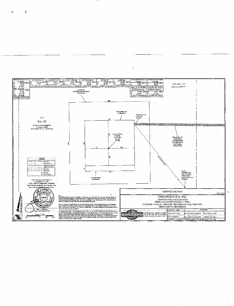
SURFACE USE PLAT
CHEVRON U.S.A. INC. PROPOSED RAD & ACCESS ROAD
SKEEN 22-26-26 FED COM NO. 7H WELL SECTIONS 13 & 22-24, T26S-R26E; SECTIONS 9 & 16-20, T26S-R27E
' EDDY COUNTY, NEW MEXICO
r - 135RBS«ncyS5.LiEay«B»,LA705GB
[ F E N S T E T R M A K E F T I Pf- 337-23M20C Fw. 337-232-02S9
DRAWN BY:-BU0 — — —
PROJ. MGR.: GDG DATE: r j2/03, , 20I4
REVISIONS
Me. 3 DATE: 04/10/2014
No. 4 DATE; 05/1572C14
REVISED BY: BMO
REVISED BY: BMO
FtLEWAME: T: t tQ13\2133315\DWGlSKEEN 22-26-26 FED COM 7H SUP.dwa

3


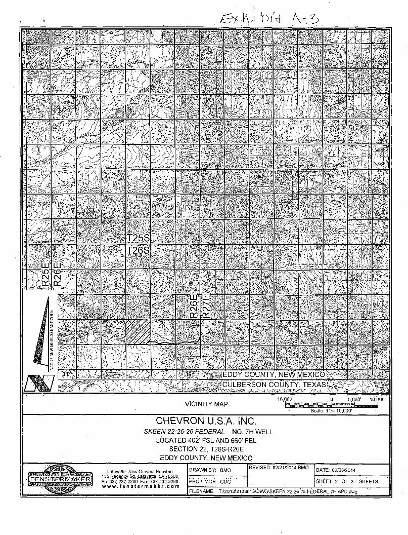
E x h i b i t A3
VICINITY MAP • 0. 1000' 2000'
Sca led" = 2000'
CHEVRON U.S.A. INC. SKEEN 22-26-26 FEDERAL NO. 7H WELL
LOCATED 402' FSL AND 660' FEL SECTION 22, T26S-R26E
EDDY COUNTY, NEW MEXICO
Ph. 337-237-2200 Fax. 337-232-3299 w w w . f e n s t e r m a k e r . c o m
DRAWN BY: BMO
PROJ. MGR.: GDG
REVISED: 02/21/2014 BMO DATE: 02/03/2014
SHEET 1 OF 3 SHEETS
FILENAME: T:\2013\2133015\DWG\SKEEN 22 26 26 FEDERAL 7H APD.dwg
/ / '
\ i -
•> /< /
•Vv- / V 1 /
/ /-s£T
< r
/ 1*
\ .
\ •v
J « /
1 J
1S I
'/ 7*J*. S T *
^
f
^ T~ A
i
s
f &
1
x 1
« ! \ ^/ " i - I j l . " I
I « ^ i ^
\ <\L \ x s \ <> - v >
C
/ , V
<
A / y
J \ ; •v.
i
wSl ^ j
/ ) ( v St ~\ i ~ < • 5 /
/
N J r y J
C*. *% ^
-V if
• A-
-i
yd
\ r
\ n
_ -1 . \
K . " ^ - ^ 1 t ^ *** Jb:
"V,
•
4 .
IS. \ :
~> ~ T25S T l r
s
\ \ z *
\ /
V V
/
i f
UJ
^6
LU
J
r I
T26S 1 7
f \ -V
/ / 1
LO CN
"CD CN
\
s
T
/ ^
•*—" ! /
•v
> *-\, v = / .
i -<-.
>
f
-«* - —' QJ ^ CD
LU i r
—
1
•
/
-V I
i •° —_ x S ^ m T l
> _>
, _ T. •> r
- r ^
s
\ 1 -
( s i JJ ..- •- i :• *C .1 HlC-
•Nl -.'.L'X ..»/<". 21 < ^ fj t Y <
>, f
i r
*
' A i - j 31 36 " ,EDDY COUNTY NEWMEXICC ) f
VICINITY MAP 10,000' 0 5,000' 10,000'
Scale: : 1" = 10,000'
CHEVRON U.S.A. INC. SKEE/V 22-26-26 FEDERAL NO. 7H WELL
LOCATED 402' FSL AND 660' FEL SECTION 22, T26S-R26E
EDDY COUNTY, NEW MEXICO
Lafayette New Orleans Houston 135 Regency S3. Lafayette, LA 70508 Ph. 337-237-2200 Fax. 337-232-329? w w w . f e n s t e r m a k e r . c o m
DRAWN BY: BMO
PROJ. MGR.: GDG
REVISED: 02/21/2014 BMO DATE: 02/03/2014
SHEET 2 OF 3 SHEETS
FILENAME: T:\2013\2133015\DWG\SKEEN 22 26 26 FEDERAL 7H APD.dwg

VICINITY MAP 2000' .•: o . IOOO'
Scale: 1." = 2000'
2000'
•• FEDERAL LAND
= STATE LAND
CHEVRON U.S.A. INC. SKEEN 22-26-26 FEDERAL NO. 7H WELL
LOCATED 402' FSL AND 660' FEL SECTION 22, T26S-R26E
EDDY COUNTY, NEW MEXICO
Lafayette New Orleans Houston 1.35. Regency Sq. Lafayette,.l_A.70508 Ph. 337-237-2200 Fax. 337-2.32-3299 w w w . f e n s t e r m a k e r . c o m
DRAWN BY: BMO
PROJ. MGR.: GDG
REVISED: 02/21/2014 BMO DATE: 02/03/2014
SHEET 3 OF 3 SHEETS
FILENAME: T:\2013\21330.15\DWG\SKEEN 22 26 26 FEDERAL 7H ARD.dwg

Skeen 22-26-26 Fed 7H Surface and Bottom Hole
1 Mile Radius T 26 R 26 Sec 22 and 15
Radii 22-26-26 Fed
Future Location Skein 23-26-26
6H BHL
Skeen 22-26-26 Fed! 7H SHL

ONSHORE ORDER NO. 1 Chevron Operating Inc. Skeen 22 26 26 Fed 7H Eddy, NM
CONFIDENTIAL -- TIGHT HOLE DRILLING PLAN
PAGE: 1
1. FORMATION TOPS
The estimated tops of important geologic markers are as follows:
FORMATION SUB-SEA KBTVD MD Castile 3043 394 Lamar 1572 1865 Bell Canyon 1532 1905 Cherry Canyon 695 2742 Brushy Canyon -403 3840 Bone Spring Limestone -1948 5385 Avalon -2058 5495 1 st Bone Spring < -2899 6336 2nd Bone Spring '> -3542 6979 3rd Bone Spring -4625 8062 Wolfcamp -4965 8402
Lateral TD (2nd Bone Spring) (4,903) 8,340 16,140
2. ESTIMATED DEPTH OF WATER, OIL, GAS & OTHER MINERAL BEARING FORMATIONS
The estimated depths at which the top and bottom of the anticipated water-, oil, gas, or other mineral bearing formations are expected to be encountered are as follows:
Substance Formation Depth Deepest Expected Base of Fresh Water 350
Water Castile 394 Water Lamar 1865 Water Bell Canyon 1905 Oil/Gas Cherry Canyon 2742 Oil/Gas Brushy Canyon 3840 Oil/Gas Bone Spring Limestone 5385 Oil/Gas Avalon 5495 Oil/Gas 1st Bone Spring 6336 Oil/Gas 2nd Bone Spring 6979 Oil/Gas 3rd Bone Spring 8062 Oil/Gas Wolfcamp 8402 All shows of fresh water and minerals will be reported and protected.
3. BOP EQUIPMENT Will have a minimum of a 5000 psi rig stack (see proposed schematic) for drill out below surface casing. Stack will be tested as specified in the attached testing requirements. Chevron requests a variance to use A coflex hose with a metal protective covering that will be utilized between the BOP and Choke manifold. Please see the attached testing and certification information.
Chevron requests a variance to use a GEA/etco SH-2 Multibowl wellhead, which will be run through the rig foor on surface casing. BOPE will be nippled up and test after cementing surface casing. Subsequent tests will be performed as needed, not to exceed 30 days. The field report from GEA/etco and BOP test information will be provided in a subsequent report at the end of the well. Please see the attached wellhead schematic. An installation manual has been placed on file with the BLM office and remains unchanged from previous submittal.

ONSHORE ORDER NO. 1 Chevron Operating Inc. Skeen 22 26 26 Fed 7H Eddy, NM
4. CASING PROGRAM a. The proposed casing program will be as follows:
CONFIDENTIAL - TIGHT HOLE DRILLING PLAN
PAGE: 2
Purpose • From To Hole Size Csg Size Weight Grade Thread Condition Surface 0' 450' 17-1/2" 13-3/8" 48 # H-40 STC New
Intermediate 0' 6,850' 12-1/4" 9-5/8" 43.5 # HCP-110 LTC New' Production 0' .16rWCr 8-1/2" 5-1/2" 17.0# HCP-110 CDC New
b. Casing design subject to revision based on geologic conditions encountered.
c. "Worst Case" casing design for wells in a particular area is used below to calculate the Casing Safety Factors. If for any reason the casing design for a particular well requires setting casing deeper than the following "worst case" design, then the Casing Safety Factors will be recalcuated & sent to the BLM prior to drilling.
d- Chevron will fill casing at a minimum of every 20 jts (840') while running for intermediate and production casing in order to maintain collapse SF.
SF Calculations based on the following "Worst Case" casing design. Surface Casing: 1500' Intermediate Casing: 7000' Production,,Casing: 16,500' MD/11,500' TVD (5000' VS @ 90 deg inc)
Casing String Min SF Burst Min SF Collapse Min SF Tension Surface 1.28 1.14 1.6
Deep Intermediate 2.83 1.36 3.27 Production 1.34 1.65 1.6
Min SF is the smallest of a group of safety factors that include the following considerations:
Burst Design Surf Int Prod
Pressure Test- Surface, Int, Prod Csg P external: Water P internal: Test psi + next section heaviest mud in csg
X X X
Displace to Gas- Surf Csg P external: Water P internal: Dry Gas from Next Csg Point
X
Frac at Shoe, Gas to Surf- Int Csg P external: Water P internal: Dry Gas, 13.5 ppg Frac Gradient
X
Stimulation (Frac) Pressures- Prod Csg P external: Water P internal: Max inj pressure w/ heaviest injected fluid
X
Tubing leak- Prod Csg (packer at KOP) P external: Water P internal: Leak just below surf, 8.7 ppg packer fluid
X
Collapse Design Full/Partial Evacuation
P external: Water gradient in cement, mud above TOC P internal: none
X X X
Cementing- Surf, Int, Prod Csg P external: Wet cement P internal: water
X X X
Tension Design 100k lb overpull X X . X

ONSHORE ORDER NO. 1 Chevron Operating Inc. Skeen 22 26 26 Fed 7H Eddy, NM
CONFIDENTIAL -- TIGHT HOLE DRILLING PLAN
PAGE: 3
5. CEMENTING PROGRAM
Slurry Type Top Bottom Weight Yield %Excess Sacks Water Surface (ppq) (sx/cu ft) Open Hole gal/sk
Tail Class C+2%CaCI 0' 450' 14.8 1.36 125 530 6.39 Intermediate
1st Stage Lead 65% Class C+ 35% Poz+ 6% Gel+ 5%
NaCI 1,650' 6,250' 12.9 1.9 100 1517 9.72
1 st Stage Tail Class C+r/oCaCI 6,250' 6,850' 14.8 1.33 100 311 6.24
2nd Stage Lead
65% Class C+ 35% Pbz+ 6% Gel+ 5%
NaCI 0' 1,792' 12.9 1.9 100 ' 532 6.24 2nd Stage Tail Class C+1%CaCI 1,792' 1,900' 14.8 1.34 100 50 6.24
Production
1 st Lead 50% Class H+ 50% Silicalite +2% Gel
6,350' 8,600' 11.3 2.54 50 311 15.07
2nd Lead 50% Class H+ 50% Silicalite +2% Gel
8,600' 16,140' 12.5 1.81 35 1424 8.10
Tail Acid Soluble Cement 15,110' 16,140' 15 2.6 0 100 11.2
1. Final cement volumes will be determined by caliper. 2. Intermediate will have a DV tool with a packer set at 1,900' to ensure all zones are covered and cement reaches to surface.
3. Surface casing shall have at least one centralizer installed on each of the bottom three joints starting with the shoe joint.
4. Production casing will have one horizontal type centralizer on every joint for the first 1000' from TD, then every other joint to EOB, and then every third joint to KOP. Bowspring type centralizers will be run from KOP to intermediate casing.
Pilot Hole Plugging Plan: Please note that this 8-3/4" Pilot Hole will TD at 8,550' within the Wolfcamp fromation, and the planned
Two cement plugs will be placed in the 8-3/4" Pilot Hole. The first will span 300' from Pilot Hole TP of 9020' Plug Slurry Type Top Bottom Weight
(ppg) Yield
(sx/cu ft) %Excess Open Hole
Sacks
Pilot Hole Plug
Plug Cement Class H 7,815' 8,550' 17.2 0.97 35 400
ONSHORE ORDER NO. 1 Chevron Operating Inc. Skeen 22 26 26 Fed 7H Eddy, NM
CONFIDENTIAL -- TIGHT HOLE DRILLING PLAN
PAGE: 4
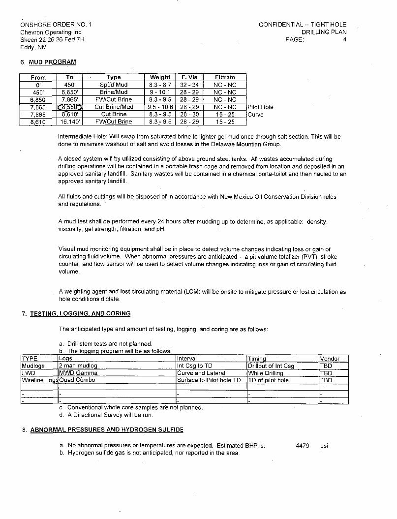
6. MUD PROGRAM
From To Type Weight F. Vis Filtrate 0'' 45.0' Spud Mud 8.3-8.7 32-34 NC - NC
450' 6,850' Brine/Mud 9-10.1 28-29 NC-NC 6,850' 7,865' FW/Cut Brine 8.3 - 9.5 28-29 NC - NC 7,865' Cut Brine/Mud 9.5 - 10.6 28-29 NC-NC 7,865' 8,610' Cut Brine 8.3 - 9.5 28-30 15-25 8,610' 16,140' FW/Cut Brine 8.3 - 9.5 28-29 15-25
Intermediate Hole: Wil swap from saturated brine to lighter gel mud once through salt section. This will be done to minimize washout of salt and avoid losses in the Delawae Mountian Group.
A closed system will by utilized consisting of above ground steel tanks. All wastes accumulated during drilling operations will be contained in a portable trash cage and removed from location and deposited in an approved sanitary landfill. Sanitary wastes will be contained in a chemical porta-toilet and then hauled to an approved sanitary landfill.
All fluids and cuttings will be disposed of in accordance with New Mexico Oil Conservation Division rules and regulations. '
A mud test shall be performed every 24 hours after mudding up to determine, as applicable: density, viscosity, gel strength, filtration, and pH.
Visual mud monitoring equipment shall be in place to detect volume changes indicating loss or gain of circulating fluid volume. When abnormal pressures are anticipated - a pit volume totalizer (PVT), stroke counter, and flow sensor will be used to detect volume changes indicating loss or gain of circulating fluid volume.
A weighting agent and lost circulating material (LCM) will be onsite to mitigate pressure or lost circulation as hole conditions dictate.
7. TESTING, LOGGING, AND CORING
The anticipated type and amount of testing, logging, and coring are as follows:
a. Drill stem tests are not planned. b. The logging program will be as follows:
TYPE Logs Interval Timing Vendor Mudlogs 2 man mudlog Int Csg to TD Drillout of Int Csg TBD LWD MWD Gamma Curve and Lateral While Drilling TBD Wireline Logs Quad Combo Surface to Pilot hole TD TD of pilot hole TBD
- - - - -- - - - -
c. Conventional whole core samples are not planned. d. A Directional Survey will be run.
8. ABNORMAL PRESSURES AND HYDROGEN SULFIDE
a. No abnormal pressures or temperatures are expected. Estimated BHP is: b. Hydrogen sulfide gas is not anticipated, nor reported in the area.
4479 psi

Chevron USA, Inc.
Chevron
TARGET INFORMATION:
8336.50' TVD <§j 0.0' VS w/0.80" Down Dip
25' Up & 25' Down
50' Left & 50' Right
Project: Eddy County, NM Site: Skeen 22 26 26 Fed
Well: Skeen 22 26 26 Fed 7H Wellbore: Wellbore #1
Plan: Plan #2 Rig: TBD
SURFACE LOCATION
US State Plane 1927 (Exact solution) New Mexico East 3001
Elevation: GL 3406.0' + KB 31.0' @ 3437.00usft (TBD) Northing Easting Latitude Longitude
371601.00 518473.00 32° 1' 17.873 N 104* 16' 25.421 W
WELLBORE TARGET DETAILS (MAP CO-ORDINATES AND LAT/LONG)
Name Skeen 22 26 26 Fed 7H BHL
Skeen 22 26 26 Fed BHL 2
TVD 8437.89 8445.00
+N/-S 7264,00 7773.73
•E/-W -23.00 -24.61
Northing 378865.00 379374.73
Easting 518450.00 518448.39
Latitude Longitude 32° 2' 29.762 N 104'16'25.641 W 32* 2' 34,807 N 104* 16' 25.657 W
SECTION DETAILS
MD Inc Azi TVD +NI-S 4E/-W Oleg TFace VSect Annotation 0.00 0.00 0.00 0.00 0.00 0.00 0.00 0.00 0.00
7865.61 0.00 0.00 7865.61 0.00 0.00 0.00 0.00 0.00 KOP/Start Build 8608.94 89 20 359.82 8343.02 470.80 -1.49 12.00 359.82 470.80 End Build
15912.62 89.20 359.82 8445.00 7773.73 -24.61 0.00 0.00 7773.77 TD
To convert a Magnetic Direction to a Grid Direction, Add 7.62°
Magnetic Model: BGGM2D13 Date: 12-May-14 Azimuths to Grid North
•• KOP/Start Build @ 7865.61'-MD*-t :-
\ - r r - Dogleg = 12.00o/10j0";
1st Bone Spring Sand
Base 1st Bone Spring Sand
m I End Build @ 8608.94' Mi>.~
I 1 "f 1" I I I 1 I I I I
1000
2nd Bone Spring Sand
|TD@ 15912.62" MDl B/2nd Bone Spring Sand
_ Hold Angle = 89.20° Iricj -
Skeen 22 26 26 Fed 7H BHL
—I—I—I 1 I 1 1 I I I I TT~T
3000 4000 5000
Vertical Section at 359.82° (1000 usft/in)
. 3rd Bone Spring Sand
mm* 3rd Bone Spring Landing
J Skeen 22 26 26 Fed BHL 2
Created By. Clyde J, Geoffrey Oate; 11:22, May22 2014_

Chevron USA, Inc.
West(-)/East(+) (1000 usft/in)
-1000 0
I i i i i I i i i i
2000
-8000
Project: Eddy County, NM Site: Skeen 22 26 26 Fed
Well: Skeen 22 26 26 Fed 7H Wellbore: Wellbore #1
Design: Plan #2 Rig: TBD
-7000
SURFACE LOCATION
US State Plane 1927 (Exact solution) New Mexico East 3001
Elevation: GL 3406.0' + KB 31.0' @ 3437.00usft (TBD) Northing Easting Latitude Longitude
371601.00 - • - - - "" "" " ' " ' 518473.00 32° 1' 17.873 N 104° 16' 25.421 W
To convert a Magnetic Direction to a Grid Direction, Add 7.62°
Magnetic Model: BGGM2013 Date: 12-May-14 Azimuths to Grid North
-4000
TARGET INFORMATION:
8336.50' TVD @ 0.0' VS w/0.80° Down Dip 25' Up & 25' Down 50' Left & 50' Right
-3000
-2000
Chevron
-1000
KOP/Start Build @ 7865.61'J^D
-2000
~" I I i I I I i I T~
-1000 0 1000
West(-)/East(+) (1000 usft/in)
N
2000 Created By: Clyde J. Geoffrey Oate: 11:21, May 22 2014

Eddy County, NM Skeen 22 26 26 Fed Skeen 22 26 26 Fed 7H
Wellbore #1
Plan: Plan #2
Proposal Report 22 May, 2014
Well Coordinates: 371,601.00 N, 518,473.00 E (32° 01' 17.87" N, 104° 16' 25.42" W)
Ground Level: 3,406.00 usft
Local Coordinate Origin: Centered on Well Skeen 22 26 26 Fed 7H
Viewing Datum: • GL 3406.0'+ KB 31.0'@ 3437.00usft (TBD)
TVDs to System: N
North Reference: Grid
Unit System: . API - US Survey Feet
Version: 5000.1 Build: 65

H A L L I B U R T O N
Chevron USA, Inc.
Eddy County, NM
Plan Report for Skeen 22 26 26 Fed 7H - Plan #2
Measured Vertical Vertical Dogleg Build Turn Todlface Depth Inclination Azimuth Depth +N/-S +E/-W Section Rate Rate Rate Azimuth (usft) (°) (°) (usft) (usft) (usft) (usft) (<71 OOusft) (°/1 OOusft) (°/1 OOusft) (°)
6,336.00
E S ^ i l S g S a n ^ / J , ^ ^ 6,496:00 0.00 0.00
i H ^ ^ ^ l Q C ? P n n g ' , S a n d **"~ *
6,979.00 ^ 0.00
7,329.00 . 0.00
7,865.61 0.00 • » S S u d d @ 7865 61JJD-^pgJeg/agpj.Spj
7,900.00 8,000.00
4.13 16.13
8,068.66 24.37
I I I I M I P S I S M 8:100.00 28.13 8,200.00 40.13 8,300.00 52.13 8,400.00 64.13
359.82 359.82 359.82 359.82
8,090.70 8,173.33 8,242.51 8,295.21
76.13 359.82 . 8,329.14 88,13 359.82 8,342.82 89.20 359.82 8,343.02
89.20 359.82 8,344.30 359.82
56.39 112.39 184.34 269.11
362.98 461.86 470.80
42.53 12.00
56.39 12.00 112.39 12.00 184.34 12.00 269.11
-1.15 -1.46 -1.49
362.98 461.86 470.80
12.00 12.00 12.00
12.00 12.00 12.00
0.00 0.00 0.00
0.00 0.00 0.00
9,400.00 9,500.00 9,600.00 9,700.00 9,800.00
9,900.00 10,000.00 10,100.00 10,200.00 10,300.00
10,400.00 10,500.00 10,600:00
89.20
89.20 89.20 89.20 89.20 89.20
89.20 89.20 89.20 89.20 89.20
89.20 89.20 89.20 89.20 89.20
89.20 89.20 89120
359.82 359.82 359.82 359.82 359.82
359.82 359.82 359.82 359.82 359.82
359.82 359.82 359.82 359.82 359.82
359.82 359.82 359". 82
8,345.69
8,347.09 8,348.48 8,349.88 8,351.28 8,352.67
8,354.07 8,355.47 8,356.86 8,358.26 8,359.65
8,361.05 8,362.45 8,363.84 8,365.24 8,366.64
8,368.03 8,369.43 8,370'.'82
561.85 -1.78 561.85" 0.00 0.00 0.00 o'oo 661.84 -2.10 661.84. 0.00 0.00 0.00 0.00
761.83 -2.41 761.83 0.00 0.00 0.00 0.00 861.82 -2.73 861.82 0.00 0.00 0.00 0.00 961.81 -3.04 961.81 0.00 0.00 0.00 0.00
1,061.80 -3.36 1,061.80 0.00 0.00 0.00 0.00 1,161.79 -3.68 1,161.79 0.00 0.00 0.00 0.00
1,261.78 -3.99 1,261.78 0.00 0.00 0.00 0.00 1,361.76 -4.31 1,361.77 0.00 0.00 0.00 0.00 1,461.75 -4.63 1,461.76 0.00 0.00 0.00 0.00 1,561.74 -4.94 1,561.75 0.00 0.00 0.00 0.00 1,661.73 -5.26 1,661.74 0:00 0.00 0.00 o.'oo 1,761.72 -5.58 1,761.73 0.00 0.00 0.00 0.00 1,861.71 -5.89 1,861.72 0.00 0.00 0.00 0.00 1,961.70 -6.21 1,961.71 0.00 0.00 0.00 0.00 2,061.69 -6.53 2,061.70 0.00 0.00 0.00 0.00 2,16'T.68 -6.84 2,161.69 0.00 0.00 0.00 0.00
2,261.67 -7.16 2,261.68 0.00 0.00 0.00 0.00 2,361.66 -7.48 2,361.67 0.00 0.00 0.00 0.00 2.461.65 -7.79 2,4§166 o.bb ojbb o.bb 0.00
22 May, 2014 - 11:32 Page 2 of 5 COMPASS

H A L L I B U R T O N
Chevron USA, Inc.
Eddy County, NM
Plan Report for Skeen 22 26 26 Fed 7H - Plan #2
Measured Vertical Vertical Dogleg Bui ld Turn Toolface
Depth Incl ination Azimuth Depth +N/-S +E/-W Section Rate Rate Rate Azimuth (usft) (°) n (usft) (usft) (usft) (usft) (°/1 OOusft) (71 OOusft) (71 OOusft) n
10,700.00 89.20 359.82 8,372.22 2 :561.64 -8.11 2,561.65 0.00 0.00 0.00 0.00 10,800.00 89.20 359.82 8,373.62 2,661.63 -8.43 2,661.65 0.00 0.00 0.00 0.00
10,900.00 89.20 359.82 8,375.01 2,761.62 -8.74 2,761.64 0.00 0.00 0.00 0.00 11,000.00 89.20 359.82 8,376.41 2,861.61 -9.06 2,861.63 0.00 0.00 0.00 0.00 11,100.00 89.20 359.82 8,377.81 2,961.60 -9.38 2,961.62 0.00 0.00 0.00 0.00 11,200.00 89.20 359.82 8,379.20 3,061.59 -9.69 3,061.61 0.00 0.00 0.00 0.00 11,300.00 89.20 359.82 8,380.60 3,161.58 -10.01 3,161.60 0.00 0.00 0.00 0.00
11,400.00 89.20 359.82 8,381.99 3,261.57 -10.33 3,261.59 0.00 0.00 0.00 0.00 11,500.00 89.20 359.82 8,383.39 3,36156 -10.64 3,361.58 0.00 0.00 0.00 o'.oo 11,600.00 89.20 359.82 8,384.79 3,461.55 -10.96 3,461.57 0.00 0.00 0.00 0.00 11,700.00 89.20 359.82 8,386.18 3,561.54 -11.28 3,561.56 0.00 0.00 0.00 0.00 11,800.00 89.20 359.82 8,387.58 3,661.53 -11.59 3,661.55 0.00 0.00 0.00 0.00
11,900.00 89.20 359.82 8,388.98 3,761.52 -11.91 3,761.54 0.00 0.00 0.00 0.00 12,000.00 89.20 359.82 8,390.37 3,861.51 -12.22 3,861.53 0.00 0.00 0.00 0.00 12,100.00 89.20 359.82 8,391.77 3,961.50 -12.54 3,961.52 0.00 0.00 0.00 0.00 12,200.00 89.20 359.82 8,393.16 4,061.49 -12.86 4,061.51 0.00 0.00 0.00 0.00 12,300.00 89.20 359.82 8,394.56 4,161.48 -13.17 4,161.50 0.00 0.00 0.00 0.00
12,400.00 89.20 359.82 8,395.96 4,261.47 -13.49 4,261.49 0.00 0.00 0.00 0.00 12,500.00 89.20 359.82 8,397.35 4,361.46 -13.81 4,361.48 0.00 0.00 0.00 0.00 12,600.00 89.20 359.82 8,398.75 4,461.45 -14.12 4,461.47 0.00 0.00 0.00 0.00 12,700.00 89.20 359.82 8,400.14 4,561.44 -14.44 4,561.46 0.00 0.00 0.00 0.00 12,800.00 89.20 359.82 8,401.54 4,661.43 -14.76 4,661.45 0.00 0.00 0.00 0.00
12,900.00 89.20 359.82 8,402.94 4,761.42 -15.07 4,761.44 0.00 0.00 0.00 0.00 13,000.00 89.20 359.82 8,404.33 4,861.41 ' -15.39 4,861.43 0.00 0.00 0.00 0.00 13,100.00 89.20 359.82 8,405.73 4,961.40 -15.71 4,961.42 0.00 0.00 0.00 0.00 13,200.00 89.20 359.82 8,407.13 5,061.39 -16.02 5,061.41 0.00 0.00 0.00 0.00 13,300.00 89.20 359.82 8,408.52 5,161.38 -16.34 5,161.40 0.00 0.00 0.00 0.00
13,400.00 89.20 359.82 8,409.92 5,261.37 -16.66 5,261.39 0.00 0.00 0.00 0.00 13,500.00 89.20 359.82 8,411.31 5,361.36 -16.97 5,361.38 0.00 0.00 0.00 0.00 13,600.00 89.20 359.82 8,412.71 5,461.34 -17.29 5,461.37 0.00 0.00 0.00 0.00 13,700.00 89.20 359.82 8,414.11 5,561.33 -17.61 5,561.36 0.00 0.00 0.00 0.00 13,800.00 89.20 359.82 8,415.50 5,661.32 -17.92 5,661.35 0.00 0.00 0.00 0.00
13,900.00 89.20 359.82 8,416.90 5,761.31 -18.24 5,761.34 0.00 0.00 0.00 0.00 14,000.00 89.20 359.82 8,418.30 5,861.30 -18.56 5,861.33 0.00 0.00 0.00 0.00 14,100.00 89.20 359.82. 8,419.69 5,961.29 -18.87 5,961.32 0.00 0.00 0.00 0.00 14,200.00 89.20 359.82 8,421.09 6,061.28 -19.19 6,061.31 0.00 0.00 0.00 0.00 14,300.00 89.20 359.82 8,422.48 6,161.27 -19.51 6,161.30 0.00 0.00 0.00 0.00
14,400.00 89.20 359.82 8,423.88 6,261.26 -19.82 6,261.29 0.00 0.00 0.00 0.00 14,500.00 89.20 359.82 8,425.28 6,361.25 -20.14 6,361.28 0.00 0.00 0.00 0.00 14,600.00 89.20 359.82 8,426.67 6,461.24 -20.45 6,461.27 0.00 0.00 0.00 0.00 14,700.00 89.20 359.82 8,428.07 6,561.23 -20.77 6,561.26 0.00 0.00 0.00 0.00 14,800.00 89.20 359.82 8,429.47 6,661.22 -21.09 6,661.26 0.00 0.00 0.00 0.00
14,900.00 89.20 359.82 8,430.86 6,761.21 -21.40 6,761.25 0.00 0.00 0.00 0.00 15,000.00 89.20 359.82 8,432.26 6,861.20 -21.72 6,861.24 0.00 0.00 0.00 0.00 15,100.00 89.20 359.82 8,433.65 6,961.19 -22.04 6,961.23 0.00 0.00 0.00 .0.00 15,200.00 89.20 359.82 8,435.05 7,061.18 -22.35 7,061.22 0.00 0.00 0.00 0.00 15,300.00 89.20 359.82 8,436.45 7,161.17 -22.67 7,161.21 0.00 0.00 0.00 0.00
15,400.00 89.20 359.82 8,437.84 7,261.16 -22.99 7,261.20 0.00 0.00 0.00 0.00 15,402.84 89.20 359.82 8,437.88 7,264.00 -23.00 7,264.04 0.00 0.00 0.00 0.00
15,500.00 89.20 359.82 8,439.24 7,361.15 -23.30 7,361.19 0.00 0.00 0.00 0.00 15,600.00 89.20 359.82 8,440.64 7,461.14 -23.62 7,461.18 0.00 0.00 0.00 0.00 15,700.00 89.20 359.82 8,442.03 7,561.13 -23.94 . 7,561.17 0.00 0.00 0.00 0.00
15,800.00 89.20 359.82 8,443.43 7,661.12 -24.25 7,661.16 0.00 0.00 0.00 0.00 15,900.00 89.20 359.82 8,444.82 7,761.11 -24.57 7,761.15 0.00 0.00 0.00 0.00 15,912.62 89.20 359.82 8,445.00 7,773.73 -24.61 7,773.77 0.00 0.00 0.00 0.00
22 May, 2014 - 11:32 Page 3 of 5 COMPASS

H A L L I B U R T O N Chevron USA, Inc.
Eddy County, NM
Plan Report for Skeen 22 26 26 Fed 7H - Plan #2
Plan Annotations
Measured Depth (usft) 7,865.61 7,865.61 8,608.94 8,608.94
15,912.62
Vertical Depth (usft) 7,865.61 7,865.61 8,343.02 8,343.02 8,445.00
Local Coordinates +N/-S (usft)
0.00 0.00
470.80 470.80
7,773.73
Vertical Section Information
Angle Type
+E/-W (usft)
0.00 0.00
-1.49 -1.49
-24.61
TD
Survey tool program
From (usft)
0.00
To (usft)
15,912.62
Target
No Target (Freehand)
Plan #2
Comment
KOP/Start Build @ 7865.61' MD Dogleg = 12.007100' End Build @ 8608.94' MD Hold Angle = 89.20° Inc. TD @ 15912.62' MD
Azimuth (°)
Origin Type
359.82 Slot
Survey/Plan
Origin start +N/_S +E/-W TVD (usft) (usft) (usft)
0.00 0.00 0.00
Survey Tool
MWD+SC
Formation Details
Measured Vertical Dip Depth Depth Name Lithology Dip Direction (usft) (usft) n ' n
394.00 394.00 Castile 0.80 359.82 1,865.00 1,865.00 Lamar LS 0.80 359.82 1,905.00 1,905.00 Bell Canyon 0.80 359.82 2,742.00 2,742.00 Cherry Canyon 0.80 359.82 3,840.00 3,840.00 Brushy Canyon 0.80 359.82 5,385.00 5,385.00 T/Bone Spring 0.80 359.82 5,495.00 5,495.00 Avalon 0.80 359.82 6,336.00 6,336.00 1st Bone Spring Sand 0.80 359.82 6,496.00 6,496.00 Base 1st Bone Spring Sand 0.80 359.82 6,979.00 6,979.00 2nd Bone Spring Sand 0.80 359.82 7,329.00 7,329.00 B/2nd Bone Spring Sand 0.80 359.82 8,068.66 8,062.00 3rd Bone Spring Sand 0.80 359.82
Targets associated with this wellbore
TVD +N/-S +E/-W Target Name (usft) (usft) (usft) Shape
Skeen 22 26 26 Fed 7H BHL 8,437.89 7,264.00 -23.00 Point Skeen 22 26 26 Fed BHL 2 8,445.00 7,773.73' -24.61 Rectangle
22 May, 2014 - 11:32 Page 4 of 5 COMPASS

H A L L I B U R T O N Chevron USA, Inc.
Eddy County, NM
North Reference Sheet for Skeen 22 26 26 Fed - Skeen 22 26 26 Fed 7H - Wellbore #1 All data is in US Feet unless otherwise stated. Directions and Coordinates are relative to Grid North Reference.
Vertical Depths are relative to GL 3406.0' + KB 31.0' @ 3437.00usft (TBD). Northing and Easting are relative to Skeen 22 26 26 Fed 7H
Coordinate System is US State Plane 1927 (Exact solution), New Mexico East 3001 using datum NAD 1927 (NADCON CONUS), ellipsoid Clarke 1866
Projection method is Transverse Mercator (Gauss-Kruger)
Central Meridian is -104.33°, Longitude Origin:0° 0' 0.000 E°, Latitude Origin:0° 0' 0.000 N°
False Easting: 500,000.00usft, False Northing: O.OOusft, Scale Reduction: 0.99990948
Grid Coordinates of Well: 371,601.00 usft N, 518,473.00 usft E Geographical Coordinates of Well: 32° 01' 17.87" N, 104° 16' 25.42" W Grid Convergence at Surface is: 0.03°
Based upon Minimum Curvature type calculations, at a Measured Depth of 15,912.62usft
the Bottom Hole Displacement is 7,773.77usft in the Direction of 359.82° (Grid).
Magnetic Convergence at surface is: -7.62° (12 May 2014, , BGGM2013)
* G Magnetic Model: BGGM2D13
Date 12-May-14 Declination 766°
- InchnatiorVDip* 5978° Field Strength 48093 t ""
« Gnd North is 0 03° East of True North (Grid Corivengence) . ^ Magnetic North is 7.66°; East of True North (MagneticDeclination) *»»•'• ' . Magnetic North is 7.62" Last of Gnd North (Magnetic Coriveroenco) *
Toc^ertaTii£DiectiontoaGndDiiection Subtract003° To convert "a M agnetic Drecton to a True4 Direction Add 7 66° East ^
« ' • --To (miata Magnetic Dratim to a Gnd Direction/Add 7:62°,::*?.:- '
22 May, 2014 - 11:32 Page 5 of 5 COMPASS

GE Oil & Gas
This drawing is the property of GE Oil & Gas Pressure Control LP and is considered confidential. Unless otherwise approved in writing, neither it nor its contents may be used, copied, transmitted or reproduced except for the sole purpose of GE Oil & Gas Pressure Control LP.
CHEVRON USA, INC. DELAWARE BASIN
13-3/8" x 9-5/8" x 5-1/2" x 2-7/8" 10M SH2/Conventional Wellhead Assembly, With DSA, T-EBS-F Tubing Head,
T-EN Tubing Hanger and A5PEN Adapter Flange
DRAWN VJK 19MAR13 13-3/8" x 9-5/8" x 5-1/2" x 2-7/8" 10M SH2/Conventional Wellhead Assembly, With DSA, T-EBS-F Tubing Head,
T-EN Tubing Hanger and A5PEN Adapter Flange
APPRV KN 19MAR13 13-3/8" x 9-5/8" x 5-1/2" x 2-7/8" 10M SH2/Conventional Wellhead Assembly, With DSA, T-EBS-F Tubing Head,
T-EN Tubing Hanger and A5PEN Adapter Flange FOR REFERENCE ONLY
DRAWING NO. AE23705

OPERATION :
Minimum System Pressure Rating :
BLOWOUT PREVENTOR SCHEMATIC
Minimum Requirements
Intermediate and Production Hole Sections
5,000 ps i
SIZE PRESSURE DESCRIPTION
A N/A B e l l N i p p l e
B 13 sir 5,000 psi A n n u l a r
C 13 S/8- 5,000 psi P i p e R a m
b 13 5/8" 5,000 ps i B l i n d R a m
E 13 5/8" 5,000 psi M u d C r o s s
F
DSA A s r e q u i r e d f o r e a c h h o l e s i ze
C7Sec
B-Sec 1 3 - 5 / 8 - 5K X 1 1 " 5K
A-Sec 1 3 - 3 / 8 " SOW X 1 3 - 5 / 8 " 5 K
I F l o w l i n e t o S h a k e r
F i l l U p L i n e
Kill Line SIZE PRESSURE DESCRIPTION 2 " 5,000 psi G a t e V a l v e
2 " 5,000 ps i G a t e V a l v e
2 " 5,000 ps i C h e c k V a l v e
Choke Line SIZE PRESSURE DESCRIPTION
3 " 5,000 psi G a t e V a l v e
3 " 5,000 p s i . HCR Valve
Kill Line- 2" minimum
•
•
•
•
•
•
Insta l la t ion Check l is t
The fo l lowing i tem mus t be ver i f ied and checked off pr ior to pressure tes t ing of BOP equipment.
The insta l led BOP equ ipment mee ts a t least the m in imum requi rements ( rat ing, type, s ize, conf igurat ion) as shown on th is schemat ic . Components may be subst i tu ted for equiva lent equipment ra ted to 'h igher pressures. Addi t ional components may be put in to p lace as long as they meet or exceed the min imum pressure rat ing of the sys tem.
AJI va lves on the k i l l l ine and choke l ine w i l l be fu l l opening and w i l l a l low s t ra ight though f low.
The k i l l l ine and choke l ine w i l l be s t ra ight unless turns use tee b locks or a re ta rge ted w i t h running tess, and w i l l be anchored to prevent wh ip and reduce v ib ra t ion .
Manual (hand wheels) or au tomat i c lock ing dev ices w i l l be insta l led on al l ram preventers. Hand wheels w i l l also be ins ta l led on al l manual valves oh the choke l ine and k i l l l ine.
A valve w i l l be insta l led in the c los ing l ine as c lose as possible to the annular preventer t o ac t as a locking device. This valve w i l l remain open unless accumula to r is inoperat ive.
Upper kel ly cock valve w i t h handle w i l l be avai lable on rig f loor along w i t h safety valve and subs t o f i t al l dr i l l s t r ing connect ions in use.
A f te r Insta l la t ion Checkl is t is comp le te , f i l l out the in format ion be low and emai l to Super intendent and Dri l l ing Engineer
Wel l na m e :
R e p r e s e n t a t i v e :
' D a t e :

CHOKE MANIFOLD SCHEMATIC
M i n i m u m R e q u i r e m e n t s
OPERATION : Intermediate and Production Hole Sections
Minimum System _ „ „ „ r,\- : 5,000 psi
Pressure Rating
C h o k e M a n i f o l d
SIZE PRESSURE DESCRIPTION 3 " 5,000 psi Panic Line Valves
2 " 5,000 p s i ; Valves on Choke Lines F l o w L i n e f r o m b e l l
n i p p l e
M u d P i t
Remote ly Opera ted
Choke
2 * L i n e t o s e p a r a t o r o r s h a k e r s
D|P=I
C u t t i n g s Pi t
3 " C h o k e L i n o f r o m BOP
V a l v e a n d G u a g o f i t f o r d r i l l i n g f l u i d
s e r v i c e
' L i n e t o t r i p t a n k
I n s t a l l a t i o n C h e c k l i s t
The fo l lowing i tem must be ver i f ied and checked off pr ior to pressure tes t ing of BOP equipment .
The insta l led BOP equ ipment meets a t least t he m in imum requi rements ( ra t ing, t ype , s ize, conf igurat ion) as shown on th is schemat ic . Components may be subst i tu ted for equivalent equ ipment ra ted to higher pressures. Addi t ional components may be pu t in to p lace as long as they meet or exceed the* min imum pressure rat ing of the sys tem.
Adjustab le Chokes may be Remotely Operated but w i l l have backup hand pump for hydraul ic ac tua t ion in case of loss of rig a i r pressure or power .
Flare and Panic l ines w i l l te rminate a m in imum of 150* f rom the wel lhead. These l ines w i l l te rminate at a locat ion as per approved APD.
The,choke l ine, k i l l l ine, and choke mani fo ld l ines w i l l be st ra ight unless turns use tee b locks or are ta rge ted w i t h running tess , 'and w i l l be anchored to prevent wh ip and reduce v ibrat ion. This exc ludes the l ine be tween mud gas separator and shale shaker .
Al l va lves (except chokes) on choice l ine, k i l l l ine, and choke mani fo ld w i l l be fu l l opening and w i l l a l low st ra ight th rough f l ow . Th is exc ludes any va lves be tween mud gas separator and shale shakers.
AH manual valves w i l l have hand whee ls ins ta l led .
If used, f lare sys tem w i l l have e f fec t ive method for ign i t ion
A l l connect ions w i l l be f langed, we lded , or c lamped (no threaded connect ions l ike hammer unions)
•
•
•
•
• • • • | | If buffer tank is used, a va lve w i l l be used on al l l ines at any entry or ex i t point to or f rom the buf fer tank .
A f te r Insta l la t ion Check l is t i s comp le te , f i l l out the in format ion below and emai l to Super intendent and Dri l l ing Engineer
Wellname:
Representative:
Date:

BOPE Testing
•
Minimum Requirements
Closing Unit and Accumulator Checklist The fo l lowing i tem must be per formed, ver i f ied, and checked off a t least once per wel l prior to low/high pressure test ing of BOP equipment. This must be repeated after 6 months on the same we l l .
Precharge' pressure for each accumulator bo t t le must fal l w i th in the.range below. . Bot t les may be further charged, w i th ni t rogen gas only. Tested precharge pressures must be recorded for each individual bott le and kept oh locat ion through-thc end of ' the we l l . Test wi l ) be .conducted prior to connect ing 'uhi t t oBOP stack.
Check • n * that applies
Accumulator work ing pressure rat ing
Minimum acceptable operat ing pressure
Desired precharge pressure
Maximum acceptable precharge pressure
Minimum acceptable "precharge pressure
' • 1500* psi 1500 psi 750 psi B00 psi 700 psi
• 2000 psi 2000 psi 1000 psi 11OO'psi 900 psi
• 3000 psi 3000 psi 1000 psi 1100. psi 900 psi
• Accumulator w i l l have suf f ic ient capac i ty to open the hydraulicalty-cohtroHed choke l ine valve (if used), close al l rams, c lose the annular preventer, and reta in a min imum of 200 psi above the max imum acceptable precharge pressure (see tab le above) on the c los ing mani fo ld w i thout the use of the c los ing pumps. This test w i l l be performed w i th test pressure recorded arid kept on locat ion through the end of the wel l
•Accumulator f lu id reservoir w i l l be double the usable f lu id volume of the accumulator system capaci ty . Fluid level w i l l be mainta ined at manufacturer 's recommendat ions. Usable f lu id volume wi l l be recorded. Rescrvior capaci ty w i l l be recorded. 'Reservoir f lu id level w i l l be recorded along w i th manufacturer 's recommendat ion. Al l w i l l be kept on locat ion through the end of the we l l .
•Closing uni t sys tem wi l l have t w o independent power sources (not count ing accumulator bott les) to close the preventers.
• Power for the closing unit pumps w i l l be avai lable to the uni t at al l t imes so tha t the pumps w i l l automat ical ly star t when the closing valve mani fo ld pressure decreases to the pre-sct level. I t is recommended to check that air l ine to accumulator pump is "ON" dur ing each tour change.
With' accumulator bot t les iso la ted, c los ing uni t w i l l be capable of opening the hydraul ical ly-bperated choke l ine valve (if used) plus c lose the annular preventer on the smal lest size dr i l l pipe wi th in .2 minutes and obtain a min imum of 200 psi above max imum acceptab le precharge pressure (see table above) on the closing mani fo ld. Test pressure and closing t ime w i l l be recorded arid kept on locat ion through the end of the we l l .
Master cont ro ls for the BOPE system w i l l be located at the accumulator and wi l l be capable of opening and closing al l preventer and the choke l ine valve (if used)
•
n I I Remote contro ls for the BOPE system w i l l be readi ly accessible (clear path) to the dri l ler and located on the rig ' ' f loor (not in the clog house). Remote 'contro ls w i l l be capable of closing al l preventers.
J [ Record accumulator tes ts in dr i l l ing reports and IADC sheet
BOPE Test Checklist The fo l lowing i tem must be ckecked off pr ior to beginning tes t
J j BLM w i l l be given at least 4 hour not ice pr ior t o beginning BOPE test ing
| | Valve on casing head below tes t p lug w i l l be open
| j Test w i l l be performed using clear wa te r .
The fo l lowing i tem must be performed during the BOPE test ing and then checked off
• BOPE w i l l be pressure tes ted when in i t ia l ly ins ta l led, whenever any seal subject to test pressure is broken, fo l lowing re lated repairs, and at a min imum of 30 days intervals. Test pressure and t imes w i l l be recorded by a 3 " party on a tes t char t and kept on locat ion through the end of the we l l .
j [ Test plug w i l l be used
[ | Ram type preventer and al l re lated wel l cont ro l equipment w i l l be tested to 250 psi ( low) and 5,000 psi (high).
J | Annular type preventer w i l l be tes ted to 250 psi ( low) and 3,500 psi (high).
• Valves w i l l be tes ted f rom the work ing pressure side w i th al l down stream valves open. The check valve w i l l be held open to tes t the k i l l l ine vafve(s)
| j Each pressure tes t w i l l be held for 10 minutes w i t h no al lowable leak off.
| | Master contro ls and remote cont ro ls to the closing uni t (accumulator) must be funct ion tested as part of the BOP test ing
| | Record BOP tests and pressures in dr i l l ing reports and IADC sheet
Af ter Insta l lat ion Checkl is t is comple te , f i l l out the informat ion below and email to Superintendent and Dril l ing Engineer along w i th anv/all BOP and accumulator tes t char ts and reports from 3 * part ies.
Wellname:
Representative:
Date:

INTERNAL HYDROSTATIC TEST CERTIFICATE
Customer: ODESSA
Customer P.O. Number: 193072
HOSE SPECIFICATIONS Type: Rotary/CHOKE KILL
GRADE E / API 7K Hose Length: 25' FEET
I.D. 3" INCHES O.D. 4.77 INCHES WORKING PRESSURE TEST PRESSURE BURST PRESSURE
10,000 PSI 15,000 PSI N/A PSI
COUPLINGS Part Number
E3.0X64WB E3.0X64WB
Stem Lot Number Ferrule Lot Number L08301765 L08301765
Type of Coupling: Die Size:
SWAGE-IT 5.25
PROCEDURE
Hose assemblv pressure tested with water at ambient temperature.
TIME HELD AT TEST PRESSURE ACTUAL BURST PRESSURE:
3 1/2 MIN. N/A PSI
Hose Assembly Serial Number: 212332
Hose Serial Number: 8104
Comments:
Date: Tested: Approyadp A
8/7/2013

Internal Hydrostatic Test Graph Hills
Midwest Mose &'Speciall)vInc.
Customer: Odessa
Hose Specifications
PickTicket#: 212332
Verification
Hose Type E
in, 3 „ „
Working Pressure 7500 PSI •
Length "25' P.P. 4.77"
Burst Pressure Standard Safety Multiplier Applies
Type pf Fitting 41/16;10K Die Size
5.'25" Hose Serial #
8104-
Coupling Method Swage
Final P.P. 5.31"
Hose Assemblv Serial tf 212332
PSI
16000
.14000
12000
10000
8000
6000
.4000
2000
0
Pressure Test —-... .. ... .
August 7, 2013
"% % % % •% Time in Minutes
Test Pressure 15000 RSI
Time Held at Test Pressure 3 2/4 Minutes
Actual'Burst Pressure Peak Pressure 15263 PSI-
C o m m e n t s : Hoseassembly pressure tested with water at.ambient temperature. Tested By:. Ryan Malone Approved By: Ryan Adams


INSET Scale: 1 "=500'
Skeen 22-26-26 Federal
No. 7H Well FSL-402' FEL-660'
TOP SOIL AREA
±0.34 Acres
PRGPOSEDPAD ±2.80 Acres
PROPOSED ^ARCHAEOLOGICAL AREA
±5.14 Acres
/
M X tf H-tr H-r t
PROPOSED ACCESS ROAD 14' X ±1-2;948.3-8(
±4.16 Acres ±784.76 Rods

E x h i b i t F
NOTE: Please be advised, that while reasonable efforts are made to locate and verify pipelines and anomalies using our standard pipeline locating ea irpment, il is impossible to be 100 % effective. As such, we advise using caution when performing work as there is a possibility that pipelines and other hazards, such as fiber optic cables, PVC pipelines,
:. may exist undetected an site.
NOTE'. Many states maintain information centers that establish links between those who dig (excavators) and those who awn and operate underground facilities (operators). It is advisable and m most stales, law, for the contractor to contact the center for assistance in locating and marking underground utilities. For guidance: New Mexico One Call - www.nmotiecall.orR
T 26 S
R 26 E
SE/SE
Sec. 23 Bureau of Land Management
PROPOSED FACILITY PAD
±1.07 Acres
PROPOSED -ARCHAEOLOGICAL
AREA ±7.19 Acres
METES AND BOUNDS DESCRIPTION DF A CALLED 1.07 ACRE FACILITY SITE
SECTION U , TZCS-RZfiE EDDY COUNTY, MEVU MEXICO
SECTION 23 T265-U6E FACULTY
SURVEY Of A PROPOSED 190f X 2«5' FACILITY SITE ON BUREAU OF LAND MANAGEMENT LANDS H THE
SOUTHEAST QUARTER Of THE SOUTHEAST QUARTER OF SECTION 23. TOWNSHIP 26 SOUTH RANGE 26 EAST,
N M f M . EDDY COUNTY, NEW MEXICO.
COMMENCING AT A FOUND 2" RON PIPE WITH BRASS CAP. LOCATED AT. THE SOUTHEAST CORNER OF SAO
SECTION 23 TOWNSHIP 26 SOUTH RANGE 2E EAST; THENCE NORTH 69 DEGREES SS MINUTES 02 SECONDS EAST
599.01 FEET TO THE POINT OF BEGINNING (P.O.B.). SAID POINT O f BEGINNING (P.O.B.) HAVHG THE
FOLLOWING COORDINATES: X- 513,903.66, ¥ • 37 ] J S 3 . 9 * (NEW MEXICO STATE PLANE COORDINATE EAST
I O N E , NAD 27).
THENCE NORTH B7 DEGREES 27 MINUTES 02 SECONDS WEST 245JM FEET;
THENCE NOItTH 0 ! OEGRtQ 31 MINUTES b i S t t O N t S EAST 19QCUEFT;
THENCE SOUTH B7 DEGREES 26 MINUTES 20 SECONDS EAST 2*4.96 f EET;
THENCE SOUTH 02 DEGREES 31 MINUTES 08 SECONDS WEST 11331 FEET TO THE POINT OF BEGINNING.
TH15 DESCRIPTION REPRESENTS A SURVEY MADE ON THE GROUND FOR A SURFACE EASEMENT AND INTENDED
SOLELY FOR THAT PURPOSE. TITLE INFORMATION WAS FURNISHED BY CHEVRON U S A . INC AND/OR THEIR
AGENTIS]. THIS DESCRIPTION DOES NOT REPRESENT A BOUNDARY SURVEY.
Sec. 26 Bureau of Land Management
Point of Commencement Fnd. 2* Iron Ppe
w/Brass Cap
FOR THE EXCLUSIVE USE OF CHEVRON U.SA. INC.
I, WM. J. Daniel 111, Rag is tared Professional Land Surveyor, do hereby state this plat is true
and correct to the best of my knowledge.
NW ARCH. AREA CRN. NE ARCH. AREA CRN. SE ARCH. AREA CRN. SW ARCH. AREA CRN.
X= 523,500 NAD 27 Y= 371,790
X= 524,099 NAD 27 Y= 371,763 ' .
X» 524.072 NAD 27 Y= 371.154
X= 523,473 NAD 27 Y= 371.190
ELEVATION +342B'NAVD 88 ELEVATION t-3420' NAVD SB ELEVATION f342V NAVD SB ELEVATION +3425* NAVD 88
NW PAD CORNER ' NE PAD CORNER SE PAD CORNER SW PAD CORNER
X= 523,667 NAD 27 Y« 371.555
X= 523,912 NAD 27 Y= 371,544
X= 523,904 NAD 27 Y» 371.354
X= 523,659 NAD 27 Y= 371,365
ELEVATION +3425' NAVD 88 ELEVATION +3420' NAVD 86 ELEVATION *3421' NAVD 68 ELEVATION »3425"NAV0 88
Scale: 1"=200'
/ 5 3 2I^S* "'" j 135 Recency Sq. LafoyoUo, LA 70508
[ F E N S T E R M A K E R ] pn337-237-2200 Fax.337.232-3299 * w w . f « R * t * r m a k « i
Not to tm uaad far construction, bkklng, rwxfdttion, eonvwynflce, **Mx, OTMVW
buMls lor lt» laumncm at M count
WM. J . Daniel III Registration No. 15076
DISCLAIMER: At this time, C.H. Fanstermaker& Associates, LLC has not performed nor was asked to perform any type of engineering, hydnotoglcal model tig, flood plain, or 'No Rise" certification analyses, including but not tanited to determining whether the project wil impact flood hazards in connection witfi foderal/FEMA, state, and/or local laws, ordinances and regulations. Accord"mgly, Fenslermaker makes no warranty or representation of any kind as to the foregoing Issues, and persons or entities using this information shall do so at their own risk.
CHEVRON U.S.A. INC. PROPOSED FACILITY PAD
SECTION 23, T26S-R26E
EDDY COUNTY, NEW MEXICO
DRAWN BY: BMO
PROJ. MGR.: GDG
DATE: 02/21/2014
REVISIONS
FILENAME: T:\2013\2132447\PWG\SECT10N 23 26 26 FACILITY SUP.dwg

E x h i b i t G l
EXHIBIT "A" METES AND BOUNDS DESCRIPTION OF A
PRpPdSED ACG^ LOCATED IN SECTIONS 22, 23 AND 24 T26S-R26E AND SECTION 19 T26S-R27E
EDDY COUNTY, NEW MEXICO
SKEEN 22 26 26 FED 7H ACCESS
SURVEY OF A PROPOSED ACCESS ROAD 16,099.60 FEET OR 975.73 RODS IN LENGTH CROSSING BUREAU
OF LAND MANAGEMENT LANDS IN SECTIONS 22, 23 AND 24 OF TOWNSHIP 26 SOUTH RANGE 26 EAST
AND SECTION 19 TOWNSHIP 26 SOUTH RANGE 27 EAST, EDDY COUNTY, NEW MEXICO.
COMMENCING AT THE SOUTHHEAST CORNER OF SAID SECTION 22 TOWNSHIP 26 SOUTH RANGE 26
EAST AT A FOUND 2 INCH IRON PIPE WITH CAP; THENCE NORTH 39 DEGREES 16 MINUTES 50 SECONDS
WEST 737.81 FEET TO THE POINT OF BEGINNING, SAID POINT OF BEGINNING HAVING THE FOLLOWIING
COORDINATES: X= 518,665.96, Y= 371,778.90 (NEW MEXICO STATE PLANE COORDINATE SYSTEM, EAST
ZONE, NAD 27).
THENCE SOUTH 89 DEGREES 20 MINUTES 18 SECONDS EAST 467.74 FEET TO A COMMON. SECTION LINE
OF SAID SECTIONS 22 AND 23 OF TOWNSHIP 26 SOUTH RANGE 26 EAST;
THENCE SOUTH 89 DEGREES 20 MINUTES 18 SECONDS EAST 189.41 FEET;
THENCE SOUTH 89 DEGREES 19 MINUTES 07 SECONDS EAST 598.78 FEET;
THENCE SOUTH 89 DEGREES 18 MINUTES 24 SECONDS EAST 68.93 FEET;
THENCE SOUTH 84 DEGREES 59 MINUTES 39 SECONDS EAST 147.81 FEET;
THENCE SOUTH 59 DEGREES 16 MINUTES 12 SECONDS EAST 381.95 FEET;
THENCE SOUTH 59 DEGREES 16 MINUTES 12 SECONDS EAST 197.51 FEET;
THENCE SOUTH 74 DEGREES 28 MINUTES 36 SECONDS EAST 428.77 FEET;
THENCE NORTH 69 DEGREES 18 MINUTES 24 SECONDS EAST 801.75 FEET;
THENCE NORTH 69 DEGREES 18 MINUTES 24 SECONDS EAST 158.84 FEET;
THENCE NORTH 87 DEGREES 45 MINUTES 07 SECONDS EAST 379.20 FEET;
THENCE SOUTH 71 DEGREES 31 MINUTES 19 SECONDS EAST 849.63 FEET;
THENCE SOUTH 71 DEGREES 31 MINUTES 19 SECONDS EAST 175.62 FEET;
THENCE SOUTH 87 DEGREES 26 MINUTES 35 SECONDS EAST 672.38 FEET;

THENCE SOUTH 84 DEGREES 40 MINUTES 34 SECONDS EAST497.25 MET "10 A COMMON SECTION LINE
OF SAID SECTIONS 23 AND 24 OF TOWNSHIP 2.6 SOUTH RANGE 26 EAST;
THENCE SOUTH 84 DEGREES 40 MINUTES 34 SECONDS EAST 99.72 FEET;
THENCE SOUTH 88 DEGREES 25 MINUTES 37 SECONDS EAST 405.19 FEET;
THENCE NORTH 66 DEGREES 33 MINUTES 43 SECONDS EAST 641.10 FEET;
THENCE NORTH 83 DEG Hi LS 07 MINUTES 28 SECONDS EAST 239.31 FEET;
THENCE NORTH 83 DEGREES 07 MINUTES 28 SECONDS EAST 108.94 FEET;
THENCE NORTH 57 DEGREES 21 MINUTES 56 SECONDS EAST 204.48 FEET;
THENCE NORTH 77 DEGREES 22 MINUTES 23 SECONDS EAST 459.92 FEET;
THENCE SOUTH 83 DEGREES 50 MINUTES 31 SECONDS EAST 597.72 FEET;
THENCE SOUTH 62 DEGREES 24 MINUTES 25 SECONDS EAST 7.70 FEET;
THENCE SOUTH 62 DEGREES 24 MINUTES 25 SECONDS EAST 312.26 FEET;
THENCE SOUTH 79 DEGREES 01 MINUTES 34 SECONDS EAST 139.98 FEET;
THENCE NORTH 63 DEGREES 48 MINUTES 32 SECONDS EAST443.65 FEET;
THENCE NORTH 85 DEGREES 51 MINUTES 03 SECONDS EAST 328.32 FEET;
THENCE SOUTH 87 DEGREES 32 MINUTES 20 SECONDS EAST 191.13 FEET;
THENCE SOUTH 87 DEGREES 32 MINUTES 20 SECONDS EAST 262.16 FEET;
THENCE SOUTH 89 DEGREES 15 MINUTES 57 SECONDS EAST 377.37 FEET;
THENCE NORTH 41 DEGREES 40 MINUTES 51 SECONDS EAST 231.36 FEET;
THENCE NORTH 33 DEGREES 37 MINUTES 09 SECONDS EAST 423.37 FEET;
THENCE NORTH 22 DEGREES 09 MINUTES 21 SECONDS EAST 256.70 FEET;
THENCE NORTH 22 DEGREES 09 MINUTES 21 SECONDS EAST 21,68 FEET;
THENCE NORTH 24 DEGREES 09 MINUTES 19 SECONDS EAST 464,81 FEET TO A COMMON SECTION LINE
OF SAID SECTION 24 OF TOWNSHIP 26 SOUTH RANGE 26 EAST AND SECTION 19 TOWNSHIP 26 SOUTH
RANGE 27 EAST;
THENCE NORTH 24 DEGREES 09 MINUTES 19 SECONDS EAST 3.1.08 FEET;

THENCE NORTH 21 DEGREES 11 MINUTES .57 SECONDS EAST 136.20 FEET;
THENCE NORTH 26 DEGREES 36 MINUTES 06 SECONDS EAST 197.99 FEET;
THENCE NORTH 50 DEGREES 13 MINUTES 01 SECONDS EAST 345.09 FEET;
THENCE NORTH 33 DEGREES 33 MINUTES 19 SECONDS WEST 121.64 FEET;
THENCE NORTH 34 DEGREES 18 MINUTES 12 SECONDS WEST 200.16 FEET;
THENCE NORTH 34 DEGREES 16 MINUTES 56 SECONDS WEST 83.98 FEET;
THENCE NORTH 34 DEGREES 16 MINUTES 56 SECONDS WEST 315.98 FEET;
THENCE NORTH 34 DEGREES 19 MINUTES 26 SECONDS WEST 32.94 FEET TO A COMMON SECTION LINE
OF SAID SECTION 19 OF TOWNSHIP 26 SOUTH RANGE 27 EAST AND SECTION 24 TOWNSHIP 26 SOUTH
RANGE 26 EAST;
THENCE NORTH 34 DEGREES 19 MINUTES 26 SECONDS WEST 42.89 FEET;
THENCE NORTH 34 DEGREES 22 MINUTES 14 SECONDS WEST 124.13 FEET;
THENCE NORTH 34 DEGREES 18 MINUTES 12 SECONDS WEST 199.64 FEET;
THENCE NORTH 34 DEGREES 24 MINUTES 42 SECONDS WEST 199.86 FEET;
THENCE NORTH 34 DEGREES 28 MINUTES 12 SECONDS WEST 210.74 FEET;
THENCE NORTH 33 DEGREES 40 MINUTES 03 SECONDS WEST 389.36 FEET;
THENCE NORTH 33 DEGREES 41 MINUTES 19 SECONDS WEST 92.19 FEET;
THENCE NORTH 33 DEGREES 41 MINUTES 19 SECONDS WEST 41.17 FEET;
THENCE NORTH 34 DEGREES 00 MINUTES 57 SECONDS WEST 1,094.08 FEET;
THENCE NORTH 34 DEGREES 00 MINUTES 57 SECONDS WEST 8,03 FEET TO THE POINT OF ENDING.
SAID POINT OF ENDING HAVING THE FOLLOWING COORDINATES; X= 528,426.21, Y= 376,111.12 (NEW
MEXICO STATE PLANE COORDINATE SYSTEM, EAST ZONE, NAD 27).
REFERENCE IS HEREBY MADE TO A SEPARATE PLAT OF THE SUBJECT PROPOSED ACCESS ROAD.
THE BEARINGS RECITED HEREON ARE ORIENTED TO NEW MEXICO STATE PLANE COORDINATE SYSTEM,
EAST ZONE, NAD 27.

THIS DESCRIPTION REPRESENTS A SURVEY MADE ON THE GROUND FOR A RIGHT OF WAY EASEMENT AND INTENDED SOLELY FOR THAT PURPOSE. THIS DESCRIPTION DOES NOT REPRESENT A BOUNDARY SURVEY.
Lafayette, LA 70508 337-237-2200

E x h i b i t G2
EXHIBIT "B" METES AND BOUNDS DESCRIPTION OF A PROPOSED ACCESS ROAD LOCATED IN
SECTIONS 17,18,19 AND 20T26S-R27E. EDDY COUNTY, NEW MEXICO
SKEEN 22 26 26 FED 7H ACCESS ROAD
SURVEY OF A PROPOSED ACCESS ROAD 9,793.97 FEET OR 593.57 RODS IN LENGTH CROSSING BUREAU
OF LAND MANAGEMENT LANDS IN SECTION 17,18, 19 AND 20 OF TOWNSHIP 26 SOUTH RANGE 27
EAST, EDDY COUNTY, NEW MEXICO.
COMMENCING AT THE SOUTHWEST CORNER OF SAID SECTION 18 TOWNSHIP 26 SOUTH RANGE 27 EAST
AT A FOUND 2 INCH IRON ROD; THENCE NORTH 75 DEGREES 49 MINUTES 38 SECONDS EAST 2,205.27
FEET TO THE POINT OF BEGINNING, SAID POINT OF BEGINNING HAVING THE FOLLOWIING
COORDINATES: X=531,893.37, Y= 377,040.25 (NEW MEXICO STATE PLANE COORDINATE SYSTEM, EAST
ZONE, NAD 27).
THENCE SOUTH 01 DEGREES 22 MINUTES 16 SECONDS EAST548.23 FEET TO A COMMON SECTION LINE
OF SAID SECTIONS 18 AND 19 TOWNSHIP 26 SOUTH RANGE 27 EAST;
THENCE SOUTH 01 DEGREES 22 MINUTES 16 SECONDS EAST 13.02 FEET;
THENCE SOUTH 89 DEGREES 46 MINUTES 05 SECONDS EAST 503.99 FEET;
THENCE SOUTH 89 DEGREES 46 MINUTES 05 SECONDS EAST 1,327.75 FEET;
THENCE SOUTH 89 DEGREES 46 MINUTES 05 SECONDS EAST 1,327.69 FEET TO A COMMON SECTION
LINE OF SAID SECTIONS 19 AND 20 TOWNSHIP 26 SOUTH RANGE 27 EAST;
THENCE SOUTH 89 DEGREES 46 MINUTES 05 SECONDS EAST 1,271.38 FEET;
THENCE SOUTH 89 DEGREES 47 MINUTES 12 SECONDS EAST 50.70 FEET;
THENCE SOUTH 89 DEGREES 47 MINUTES 12 SECONDS EAST 250.36 FEET;
THENCE SOUTH 89 DEGREES 47 MINUTES 15 SECONDS EAST 290.34 FEET;
THENCE SOUTH 89 DEGREES 46 MINUTES 46 SECONDS EAST 308.97 FEET;
THENCE SOUTH 89 DEGREES 46 MINUTES 31 SECONDS EAST 301.64 FEET;
THENCE SOUTH 89 DEGREES 47 MINUTES 31 SECONDS EAST 170.80 FEET;
THENCE SOUTH 89 DEGREES 47 MINUTES 31 SECONDS EAST 127.39 FEET;

THENCE SOUTH 89 DEGREES 46 MINUTES 50 SECONDS EAST 301.25 FEET;
THENCE SOUTH 89 DEGREES 47 MINUTES 09 SECONDS EAST 300.52 FEET;
THENCE SOUTH 89 DEGREES 46 MINUTES 47 SECONDS EAST 301.73 FEET;
THENCE SOUTH 86 DEGREES 35 MINUTES 26 SECONDS EAST 292.02 FEET;
THENCE SOUTH 86 DEGREES 35 MINUTES 26 SECONDS EAST 102.04 FEET;
THENCE SOUTH 85 DEGREES 07 MINUTES 38 SECONDS EAST99.85 FEET;
THENCE NORTH 11 DEGREES 29 MINUTES 25 SECONDS WEST 56.97 FEET TO A COMMON SECTION LINE
OF SAID SECTIONS 20 AND 17 TOWNSHIP 26 SOUTH RANGE 27 EAST;
THENCE NORTH 11 DEGREES 29 MINUTES 25 SECONDS WEST 71.61 FEET;
THENCE NORTH 10 DEGREES 22 MINUTES 52 SECONDS WEST 359.43 FEET;
THENCE NORTH 10 DEGREES 20 MINUTES 45 SECONDS WEST 299.43 FEET;
THENCE NORTH 10 DEGREES 17 MINUTES 33 SECONDS WEST 321.17 FEET;
THENCE NORTH 10 DEGREES 19 MINUTES 24 SECONDS WEST 68.34 FEET;
THENCE NORTH 10 DEGREES 19 MINUTES 24 SECONDS WEST 210.50 FEET;
THENCE NORTH 09 DEGREES 50 MINUTES 58 SECONDS WEST 23.46 FEET;
THENCE NORTH 09 DEGREES 50 MINUTES 58 SECONDS WEST 493.40 FEET TO THE POINT OF ENDING.
SAID POINT OF ENDING HAVING THE FOLLOWING COORDINATES; X= 538,894.17, Y= 378,293.90 (NEW
MEXICO STATE PLANE COORDINATE SYSTEM, EAST ZONE, NAD 27).
REFERENCE IS HEREBY MADE TO A SEPARATE PLAT OF THE SUBJECT PROPOSED ACCESS ROAD.
THE BEARINGS RECITED HEREON ARE ORIENTED TO NEW MEXICO STATE PLANE COORDINATE SYSTEM, EAST ZONE, NAD 27.
THIS DESCRIPTION REPRESENTS A SURVEY MADE ON THE GROUND FOR A RIGHT OF WAY EASEMENT AND INTENDED SOLELY FOR THAT PURPOSE. THIS DESCRIPTION DOES NOT REPRESENT A BOUNDARY SURVEY.

Lafayette, LA 70508 337-237-2200

E x h i b i t H
LEGEND
-x-Section Line
Existing Fenceline
Existing Road
NORTH PAD CORNER
530,167 NAD 27
373,460
ELEVATION •+3372';NAVD 88
EAST PAD.CORNER
530,375 NAD 27
373,211
ELEVATION +3369' NAVD £
SOUTH.PAD CORNER.
530,145 NAD 27
373,019
ELEVATION+3371'NAVD 88
WEST PAD.CORNER
'529,937 NAD 27 373,268
ELEVATION +3375" NAVD £
Sec. 24 Bureau of Land Management
Proposed Skeen
22 26 26 Federal
7H Access Road
/ /
V II
II II
NOTE PLEASE BE ADVISED, THAT WHILE REASONABLE EFFORTS ARE MADE TO LOCATE AND VERIFY PIPELINES AND ANOMALIES USING OUR STANDARD PIPELINE LOCATING EQUIPMENT, IT IS IMPOSSIBLETO BE 100% EFFECTIVE. AS SUCH, WE ADVISE USING CAUTION WHEN PERFORMING WORK AS THERE IS A POSSIBILITY THAT PIPELINES AND OTHER HAZARDS, SUCH AS FIBER OPTIC CABLES, PVC PIPELINES, ETC. MAY EXIST UNDETECTED'ON SITE.
MANY STATES MAINTAIN INFORMATION CENTERS THAT ESTABLISH LINKS BETWEEN THOSE WHO DIG (EXCAVATORS) AND THOSE WHO OWN AND OPERATE UNDERGROUND FACILITIES (OPHWtORSL' IT IS ADVISABLE AND IN MOST STATES, LAW, FOR THE CONTRACTOR f O'CONTACT THE CENTER FOR ASSISTANCE IN LOCATING AND MARKING UNDERGROUND UTILITIES. NEW MEXICO ONE CALL, ' vm.hmonfcaiA'g'
DISCLAIMER: AT THIS TIME, C. H. FENSTERMAKER 4 ASSOCIATES, LLC. HAS NOT PERFORMED NOR WAS ASKED TO PERFORM ANYTYPE OF ENGINEERING, HYDROLOGICAL MODELING. FLOOD PLAIN. OR "NO RISE' CERTIFICATION ANALYSES, INCLUDING BUT NOT LIMITED TO DETTOTNING.WHETHER'THE PROJECT WILL IMPACT FLObD.HAZARDS IN CONNECTION WiTW FEDEP^UFEf A, STATED AND/OR LOCAL LAWS, ORDINANCES AND REGULATIONS. ACCORDINGLY/FENSY REPRESENTATION OF ANY KIND AS TO THE FOREGOING ISSUES, AND PERSONS OR ENTITIES USING THIS INFORMATION SHALL DO SO AT THEIR OWN RISK.
FOR THE EXCLUSIVE USE OF
CHEVRON U.S.A. INC.
I, WM. J. Daniel il l, Registered Professional
Land Surveyor, do hereby state this plat is true
and correct to the best of my knowledge.
Point of Beginning
Sec. 19 Bureau of Land Management
To Point of Commencement/Fnd
. 2" Iron Pipe w/3" Brass cap
SURFACE USE PLAT 200'
Scale: 1 "=200'
100' 200'
CHEVRON U.S.A. INC. PROPOSED FRAC POND
SKEEN 22 26 26 FED COM NO. 7H WELL SECTION 19, T26S-R27E
EDDY COUNTY, NEW MEXICO
135 Regency Sq. Lafayette, LA 70508 Ph. 337-237,2200 .Fax,337-232-3299 w w w . f e n s t e r m a k e r . c o m
D R A W N BY: BMO
PROJ. MGR.: GDG
DATE: MAY 06, 2014
REVISIONS
No.
No.
DATE:
DATE:
REVISED BY:
REVISED BY:
FILENAME: T:\201.3\2133015\pWG\SKEEN,FRAC POND.dwg

METES AND BOUNDS DESCRIPTION OF A PROPOSED FRAC POND LOCATED IN
SECTION 19 T26S-R27E. EDDY COUNTY, NEW MEXICO
PROPOSED SKEEN 22 26 26 FED COM NO. 7H FRAC POND
SURVEY OF A PROPOSED 2.24 ACRE FRAC POND ON BUREAU OF LAND MANAGEMENT LAND LOCATED IN
THE NORTHWEST QUARTER OF THE SOUTHWEST QUARTER OF SECTION 19, TOWNSHIP 26 SOUTH
RANGE 27 EAST, N.M.P.M. EDDY COUNTY, NEW MEXICO.
COMMENCING AT THE SOUTHWEST CORNER OF SAID SECTION 19 TOWNSHIP 26 SOUTH RANGE 27 EAST
ATA FOUND 2 INCH IRON PIPE WITH 3 INCH BRASS CAP; THENCE NORTH 10 DEGREES 47 MINUTES 42
SECONDS EAST 1,885.10 FEET TO THE POINT OF BEGINNING, SAID POINT OF BEGINNING HAVING THE
FOLLOWING COORDINATES: X= 530,144,94, Y= 373,018.54 (NEW MEXICO STATE PLANE COORDINATE
SYSTEM, EAST ZONE, NAD 27).
THENCE NORTH 39 DEGREES 48 MINUTES 04 SECONDS WEST 324.97 FEET;
THENCE NORTH 50 DEGREES 12 MINUTES07 SECONDS EAST300.05 FEET;
THENCE SOUTH 39 DEGREES 47 MINUTES 48 SECONDS EAST 324.97 FEET;
THENCE SOUTH 50 DEGREES 12 MINUTES 14 SECONDS WEST 300.03 FEET TO THE POINT OF ENDING.
SAID POINT OF ENDING HAVING THE FOLLOWING COORDINATES; X= 530,144.94, Y= 373,018.54 (NEW
MEXICO STATE PLANE COORDINATE SYSTEM, EAST ZONE, NAD 27).
REFERENCE IS HEREBY MADE TO A SEPARATE PLAT OF THE SUBJECT PROPOSED FRAC POND.
THE BEARINGS RECITED HEREON ARE ORIENTED TO NEW MEXICO STATE PLANE COORDINATE SYSTEM, EAST ZONE, N AD 27.
THIS DESCRIPTION REPRESENTS A SURVEY MADE ON THE GROUND FOR A PROPOSED FRAC POND AND INTENDED SOLELY FOR THAT PURPOSE. THIS DESCRIPTION DOES NOT REPRESENT A BOUNDARY SURVEY.

WM.fl. Daniel RegistV(ed Professi C. H. Fen? 135 Regency Square Lafayette, LA 70508 337-237-2200
al Land Surveyor # 15078 Associates, LLC
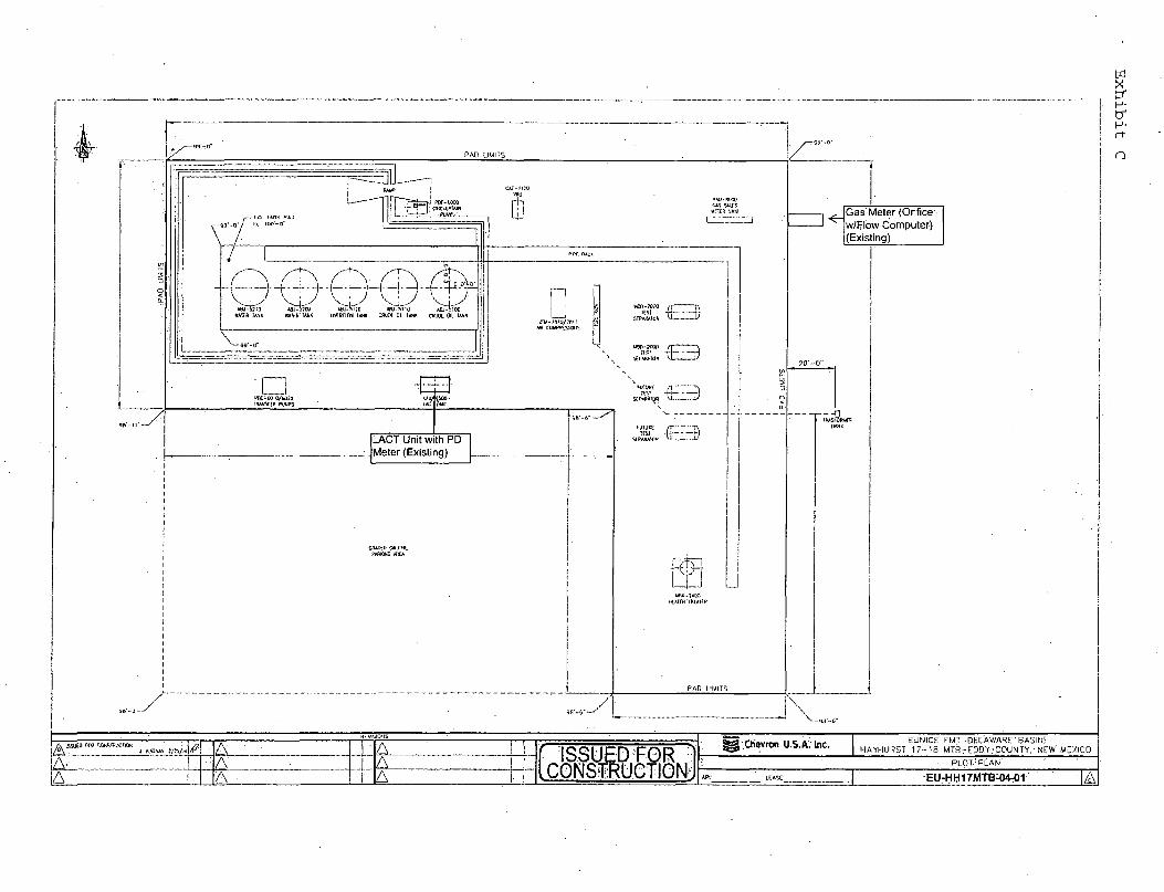
MU-tBOO
v i m b*to
A W ^ E T ASJ IJOO WJ-^I!O ABJ-THO A&J-5IOO KAHft lANK WWRTANK (MfHT.tr* lANK CUtOt 01. I «« CMJOC Ol W «
LACT Unit with PD Meter (Existing)
SfPASATOH NI 1'
5£P*W!Ofi M V
umiKE / j r : m r
StPARAKW L
Gas-Meter (Orifice w/Hlow Computer) (Existing)
AL A
:A_ A
A A
ISSUED FOR i CONSTRUCTION
Chevron U.S.A.'Inc. EUNICE FMT-DELAWARE-'BASINf
HAYHURST 1 7 - 1 8 MTBrEPD.Y'COUNTY,: NEW MEXICO
PLOT. PLAN
EU-HH17MTB^W-01

CONFIDENTIAL - TIGHT HOLE SURFACE USE PLAN
ONSHORE OIL & GAS ORDER NO. 1 Approval of Operations on Onshore
Federal and Indian Oil and Gas Leases
Skeen 22 26 26 Fed Com 7H 402' FSL and 660' FWL Section 22, Township 26, Range 26 Eddy County, New Mexico
A. EXISTING ROADS/LEASE ROADS
Driving directions are from Malaga, New Mexico, south on the Pecos Hwy. U.S. 285 11.2 miles and turn west onto White City Road (CR 724) and go west approximately 8 miles and turn south approximately 5 miles to the location. The location is approximately 24 miles from the nearest town, which is Malaga, NM.
The proposed access road is approximately 5 miles in length and 14' in travel way width with a maximum disturbance area of 20' will be used, and in accordance with guidelines set forth in the BLM Onshore Orders. No turnouts are expected.
Existing county and lease roads will be used to enter proposed access road.
The existing road is measured from White City Road.
25,892.97' Total Length of New and Existing Roads 16,099.60' Total Length of New and Existing Roads in S22, 23, and 24
+ 9,793.97' Total Length of New and Existing Roads in S17, 18, 19, and 20
Surface disturbance and vehicular travel will be limited to the approved location and approved access route. Any additional area needed will be approved in advance.
Location, access, and vicinity plats attached hereto. See Exhibits A-1 to A-3. Please see Exhibit A2 for the location of the access road to the well pad. Please see Exhibits G1 and G2 for the legal description of access road.
Chevron will maintain existing roads in a condition the same or better than before operations begin. All existing structures on the entire access route such as cattle guards, culverts, fences, etc. will be properly repaired or replaced if they are damaged or have deteriorated beyond practical use. All pot holes, drainages, road crowns, etc., will be repaired to maintain current road conditions. We will prevent and abate fugitive dust as needed, whether created by vehicular traffic, equipment operations, or high wind events. BLM written approval will be acquired before application of surfactants, binding agents, or other dust suppression chemicals on roadways.
ONSHORE ORDER NO. 1 Chevron
Page 1 of 8

ONSHORE ORDER NO. 1 CONFIDENTIAL - TIGHT HOLE Chevron SURFACE USE PLAN
B. NEW OR RECONSTRUCTED ACCESS ROADS
There will be approximately 3 miles of new access to be constructed.
All existing roads (previously improved) will be used "as is" with the exception of minor blading as needed.
Surface disturbance and vehicular travel will be limited to the approved access route. Any additional area will be approved in advance.
Road Width: 1 4 - 2 0 feet traveling surface.
Maximum Grade: Road gradient less than 8%
Crown Design: 2%
Turnouts will be installed along the access route as needed.
Ditch design: Drainage, interception and outlet.
Erosion Control: 6" rock under road.
Re-vegetation of Disturbed Area: All disturbed areas will be seeded by Broadcast or Drill and Crimp. Ground conditions will determine the method used.
Cattle guard(s) will be installed as needed.
Major Cuts and Fills: 2:1 Slope.
Surfacing material (road base derived from caliche or river rock) will be placed on the access road during construction. All surface disturbing activities will be discussed with and agreed to with the surface owner.
C. LOCATION OF EXISTING WELLS
All wells located within a 1-mile radius of the Surface & Bottom Hole Location. See Exhibit B.
D. LOCATION OF PRODUCTION FACILITIES
It is anticipated that production facilities will be located in the Southeast corner of Sec 23-26-26, east of the Skeen 23-26-26 Fed 6H well pad and oil to be sold at that tank battery.
The production line will be dual surface-laid 4" flex pipe with a working pressure less than 125 psig ran along existing disturbances.
Page 2 of 8

ONSHORE ORDER NO. 1 CONFIDENTIAL - TIGHT HOLE Chevron SURFACE USE PLAN
Oil and gas measurement will be installed on this well location. See Exhibit C.
The permanent water disposal system will be determined prior to construction of any water transfer pipeline. Until permanent water takeaway is available, produced water will be hauled off location in trucks.
The permanent electrical supply route will be determined prior to construction of permanent distribution lines. A generator will be utilized until permanent power is connected.
E. LOCATION AND TYPES OF WATER SUPPLY
Chevron will utilize the fresh water holding pond in Section 19-26-27 for fresh water. Please see Exhibit H for the location of the frac pond.
During frac operations, Chevron will lay a temporary 12" flowline from the frac pond to the well. The flowline will follow within 5 feet along the access road from the frac pond to the well using the same route as the proposed production road depicted on Exhibits A2 and G.
Water will be obtained from a private water source into Section 19-26-27. The source provider and exact location have not been finalized at this time. Most likely, Chevron expects to transfer water from the source well or distribution center using a temporary 4" poly pipe transfer line. Chevron will submit a sundry notice at a later date, including a plat that depicts the proposed location of the temporary 4" poly pipe transfer line to fill the frac pond.
F. CONSTRUCTION MATERIALS
All construction materials will be used from the nearest Private, BLM, or State pit. All material (i.e. shale) will be acquired from private or commercial sources.
No construction material will be needed for well pad construction; subsurface spoil material will be utilized.
Surfacing material (caliche) will be purchased from a supplier having a permitted source of materials.
The entire location will be fenced with barb/woven wire.
Page 3 of 8

ONSHORE ORDER NO. 1 CONFIDENTIAL - TIGHT HOLE Chevron SURFACE USE PLAN
G. METHODS FOR HANDLING WASTE DISPOSAL
A closed system will be utilized consisting of above ground steel tanks.
All wastes accumulated during drilling operations will be contained in a portable trash cage and removed from location and deposited in a state approved facility.
Disposal of cuttings: Tervita, LLC
Sewage and gray water before and after treatment are not allowed to be discharged to the ground. They are collected from storage tank(s) and portable potty at drilling and completions locations and transported by an approved transporter to be disposed of at a Chevron's select-for-use disposal facility.
H. ANCILLARY FACILITIES None.
I. WELLSITE LAYOUT The proposed site layout plat is attached showing the Ensign 767 orientation and equipment location. See Exhibit D.
In order to level the location, cut and fill will be required. Please see attached Well Location and Acreage Dedication Plat - Exhibits A-1 to A-4.
A locking gate will be installed at the site entrance.
Any fences cut will be repaired. Cattle guards will be installed, if needed.
J . PLANS FOR RECLAMATION OF THE SURFACE
In the Event of Production
Within 6 months, Chevron will contact BLM Surface Management Specialists to devise the best strategies to reduce the size of the location. Current plans for interim reclamation will consist of reclaiming the pad to +/-50 feet outside the anchors, or approximately 200 x 200 feet. See Exhibit E.
In addition, the following procedures shall be followed: i. Caliche will be removed from reclaimed areas to increase the success of revegetation.
Removed caliche that is free of contaminants may be reused for future projects. ii. The portions of the cleared well site not needed for operational and safety purposes will
be re-contoured to a final or intermediate contour that blends with the surrounding
Page 4 of 8

ONSHORE ORDER NO. 1 Chevron SURFACE USE PLAN
CONFIDENTIAL - TIGHT HOLE
topography as much as possible. Sufficient level area remains for setup of a workover rig and to park vehicles/equipment.
iii. All surface soil materials (topsoil) are to be removed from the entire cut and fill area and temporarily stockpiled for reuse during interim reclamation. Topsoil will be respread over areas not needed for all-weather operations to ensure successful revegetation. Any topsoil pile set aside should be revegetated to prevent it from eroding and to help maintain its biological viability.
iv. After all disturbed areas have been satisfactorily prepared, these areas need to be revegetated with the seed mixture advised by the BLM. The seed mix will be evenly and uniformly distributed over the disturbed area. Seeding will be accomplished by using a drilling or, when drilling.is not available, by broadcasting the seed. When broadcasting the seed, the amount of seed shall be doubled.
v. Weed control will be used on disturbed land, including the roads, pads, associated pipeline corridor, and adjacent land affected by the operations. There shall be no primary or secondary noxious weeds in the seed mixture used for reseeding.
In the Event of a Dry Hole/Final Reclamation
Upon final abandonment of the well, a new reclamation plan will be submitted with the Notice of Intent to Abandon (NIA) or Subsequent Report Plug and Abandon (SRA) using the Sundry Notices and Reports on Wells Form 3160-5. The location will be restored to as near as original condition as possible. Reclamation of the surface shall be done in strict compliance with the existing New Mexico Oil Conservation Division regulations and BLM regulations.
In addition, the following procedures shall be followed: i. Caliche material from the well pad and access road will be removed and utilized to re-
contour to a final contour that blends with the surrounding topography as much as possible. Any caliche material not used will be utilized to repair roads within the lease.
ii. On sloped ground, the topsoil and interim vegetation will be restripped from portions of the site that are not at the original contour, the well pad recontoured, and the topsoil will be respread over the entire disturbed.
iii. Topsoil will be distributed over the reclamation area and cross ripped to control erosion iv. After all disturbed areas have been satisfactorily prepared, these areas need to be
revegetated with the seed mixture advised by the BLM. The seed mix will be evenly and uniformly distributed over the disturbed area. Seeding will be accomplished by using a drilling or, when drilling is not available, by broadcasting the seed. When broadcasting the seed, the amount of seed shall be doubled.
v. Weed control will be used on disturbed land, including the roads, pads, associated pipeline corridor, and adjacent land affected by the operations. There shall be no primary or secondary noxious weeds in the seed mixture used for reseeding.
Page 5 of 8

ONSHORE ORDER NO. 1 Chevron SURFACE USE PLAN
CONFIDENTIAL - TIGHT HOLE
K. SURFACE TENANT . Owen Carletbn
Po Box 14 Malaga NM. 88263 575-361-9989
ROAD OWNERSHIP All access roads are located on Federal lands.
L. ADDITIONAL INFORMATION Class III cultural resource inventory report was prepared by Boone Arch Services of NM, LLC (506 E. Chapman Rd, Carlsbad, NM 88220) for the proposed location. A copy of the report has been sent to the BLM office under separate cover and is also attached for reference.
Page 6 of 8
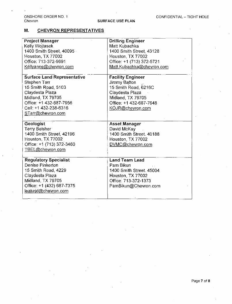
ONSHORE ORDER NO. 1 CONFIDENTIAL - TIGHT HOLE Chevron SURFACE USE PLAN
M. CHEVRON REPRESENTATIVES
Project Manager Kelly Wojtasek 1400 Smith Street, 40095 Houston, TX 77002 Office: 713-372-9691 Kellyanne(5>ehevron.com
Drilling Engineer Matt Kubachka 1400 Smith Street, 43128 Houston, TX 77002 Office:+1 (713) 372-5721 [email protected]
Surface Land Representative Stephen Tarr 15 Smith Road, 5103 Claydesta Plaza Midland, TX 79705 Office: +1 432-687-7956 Cell: +1 432-238-6316 STarr(5)chevron.com
Facility Engineer Jimmy Batton r
15 Smith Road, 6216C Claydesta Plaza Midland, TX 79705 Office: +1 432-687-7648 KOJR(5)chevron.com
Geologist Terry Belsher 1400 Smith Street, 42196 Houston, TX 77002 Office: +1 (713) 372-3460 TBEL(5)chevron.corn
Asset Manager David McKay 1400 Smith Street. 40188 Houston, TX 77002 DVMC(5)chevron.com
Regulatory Specialist Denise Pinkerton 15 Smith Road, 4229 Claydesta Plaza Midland, TX 79705 Office: +1 (432) 687-7375 [email protected]
Land Team Lead Pam Bikun 1400 Smith Street. 45004 Houston, TX 77002 Office: 713-372-1373 [email protected]
Page 7 of 8
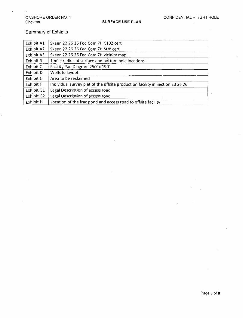
ONSHORE ORDER NO. 1 Chevron SURFACE USE PLAN
CONFIDENTIAL - TIGHT HOLE
Summary of Exhibits
Exhibit A l Skeen 22 26 26 Fed Com 7H C102 cert
Exhibit A2 Skeen 22 26 26 Fed Com 7H SUP cert
Exhibit A3 Skeen 22 26 26 Fed Com 7H vicinity map
Exhibit B 1 mile radius of surface and bottom hole locations.
Exhibit C Facility Pad Diagram 250' x 190'
Exhibit D Wellsite layout
Exhibit E Area to be reclaimed
Exhibit F Individual survey plat of the offsite production facility in Section 23 26 26
Exhibit G l Legal Description of access road
Exhibit G2 Legal Description of access road
Exhibit H Location of the frac pond and access road to offsite facility
Page 8 of 8

PECOS DISTRICT CONDITIONS OF APPROVAL
OPERATOR'S NAME: Chevron USA Inc LEASE NO.: NM113943
WELL NAME & NO.: 7H-Skeen 22 26 26 Federal SURFACE HOLE FOOTAGE: ' 4027S & 6607E
BOTTOM HOLE FOOTAGE 23107S &6607E, sec. 15 LOCATION: Sec. 22, T. 26 S., R. 26 E.
COUNTY: Eddy County, New Mexico
T A B L E O F C O N T E N T S Standard Conditions of Approval (COA) apply to this APD. If any deviations to these
standards exist or special COAs are required, the section with the deviation or requirement will be checked below.
I I General Provisions I I Permit Expiration I I Archaeology, Paleontology, and Historical Sites
Noxious Weeds IXI Special Requirements
Cave and Karst Requirements Communitization Agreement
Construction Notification Topsoil Closed Loop System Federal Mineral Material Pits Well Pads Roads
I I Road Section Diagram [El Drilling
Cement Requirements High Cave/Karst Logging Requirements Waste Material and Fluids
3 Production (Post Drilling) Well Structures & Facilities ' Pipelines Frac Pond Temporary Frac Lines
I I Interim Reclamation I I Final Abandonment & Reclamation
Page 1 of24
I. GENERAL PROVISIONS
The approval of the Application For Permit To Drill (APD) is in compliance with all applicable laws and regulations: 43 Code of Federal Regulations 3160, the lease terms, Onshore Oil and Gas Orders, Notices To Lessees, New Mexico Oil Conservation Division (NMOCD) Rules, National Historical Preservation Act As Amended, and instructions and orders of the Authorized Officer. Any request for a variance shall be submitted to the Authorized Officer on Form 3160-5, Sundry Notices and Report on Wells.
II. PERMIT EXPIRATION
If the permit terminates prior to drilling and drilling cannot be commenced within 60 days after expiration, an operator is required to submit Form 3160-5, Sundry Notices and Reports on Wells, requesting surface reclamation requirements for any surface disturbance. However, i f the operator will be able to initiate drilling within 60 days after the expiration of the permit, the operator must have set the conductor pipe in order to allow for an extension of 60 days beyond the expiration date of the APD. (Filing of a Sundry Notice is required for this 60 day extension.)
III. ARCHAEOLOGICAL, PALEONTOLOGY & HISTORICAL SITES
Any cultural and/or paleontological resource discovered by the operator or by any person working on the operator's behalf shall immediately report such findings to the Authorized Officer. The operator is fully accountable for the actions of their contractors and subcontractors. The operator shall suspend all operations in the immediate area of such discovery until written authorization to proceed is issued by the Authorized Officer. An evaluation of the discovery shall be made by the Authorized Officer to determine the appropriate actions that shall be required to prevent the loss of significant cultural or scientific values of the discovery. The operator shall be held responsible for the cost of the proper mitigation measures that the Authorized Officer assesses after consultation with the operator on the evaluation and decisions of the discovery. Any unauthorized collection or disturbance of cultural or paleontological resources may result in a shutdown order by the Authorized Officer.
IV. NOXIOUS WEEDS
The operator shall be held responsible if noxious weeds become established within the areas of operations. Weed control shall be required on the disturbed land where noxious weeds exist, which includes the roads, pads, associated pipeline corridor, and adjacent land affected by the establishment of weeds due to this action. The operator shall consult with the Authorized Officer for acceptable weed control methods, which include following EPA and BLM requirements and policies.
Page 2 of 24

V. SPECIAL REQUIREMENTS
Cave and Karst
Depending on location, additional Drilling, Casing, and Cementing procedures may be required by engineering to protect critical karst groundwater recharge areas.
Cave/Karst Surface Mitigation The following stipulations will be applied to minimize impacts during construction, drilling and production.
Construction: In the advent that any underground voids are opened up during construction activities, construction activities will be halted and the BLM will be notified immediately.
No Blasting: No blasting will be utilized for pad construction. The pad will be constructed and leveled by adding the necessary fill and caliche.
Pad Berming: The entire perimeter of the well pad will be bermed to prevent oil, salt, and other chemical contaminants from leaving the well pad. • The compacted berm shall be constructed at a minimum of 12 inches high with
impermeable mineral material (e.g. caliche). o No water flow from the uphill side(s) of the pad shall be allowed to enter the well
pad. « The topsoil stockpile shall be located outside the bermed well pad. • Topsoil, either from the well pad or surrounding area, shall not be used to construct
the berm. • No storm drains, tubing or openings shall be placed in the berm. • If fluid collects within the bermed area, the fluid must be vacuumed into a safe
container and disposed of properly at a state approved facility. • The integrity of the berm shall be maintained around the surfaced pad throughout the
life of the well and around the downsized pad after interim reclamation has been completed.
• Any access road entering the well pad shall be constructed so that the integrity of the berm height surrounding the well pad is not compromised. (Any access road crossing the berm cannot be lower than the berm height.)
Tank Battery Liners and Berms: Tank battery locations and all facilities will be lined and bermed. A 20 mil permanent liner will be installed with a 4 oz. felt backing to prevent tears or punctures. Tank battery berms must be large enough to contain 1 Vi times the content of the largest tank.
Leak Detection System:
Page 3 of24

A method of detecting leaks is required. The method could incorporate gauges to measure loss, situating values and lines so they can be visually inspected, or installing electronic sensors to alarm when a leak is present. Leak detection plan will be submitted to BLM for approval.
Automatic Shut-off Systems: Automatic shut off, check values, or similar systems will be installed for pipelines and tanks to minimize the effects of catastrophic line failures used in production or drilling.
Cave/Karst Subsurface Mitigation The following stipulations will be applied to protect cave/karst and ground water concerns:
Rotary Drilling with Fresh Water: Fresh water will be used as a circulating medium in zones where caves or karst features are expected. SEE ALSO: Drilling COAs for this well.
Directional Drilling: Kick off for directional drilling will occur at least 100 feet below the bottom of the cave occurrence zone. SEE ALSO: Drilling COAs for this well.
Lost Circulation: ALL lost circulation zones from the surface to the base of the cave occurrence zone will be logged and reported in the drilling report.
Regardless of the type of drilling machinery used, i f a void of four feet or more and circulation losses greater than 70 percent occur simultaneously while drilling in any cave-bearing zone, the BLM will be notified immediately by the operator. The BLM will assess the situation and work with the operator on corrective actions to resolve the problem.
Abandonment Cementing: Upon well abandonment in high cave karst areas additional plugging conditions of approval may be required. The BLM will assess the situation and work with the operator to ensure proper plugging of the wellbore.
Pressure Testing: Annual pressure monitoring will be performed by the operator on all casing annuli and reported in a sundry notice. If the test results indicated a casing failure has occurred, remedial action will be undertaken to correct the problem to the BLM's approval.
Page 4 of24

Communitization Agreement A Communitization Agreement covering the acreage dedicated to this well must be filed for approval with the BLM. The effective date of the agreement shall be prior to any sales. In addition, the well sign shall include the surface and bottom hole lease numbers. If the Cominunitization Agreement number is known, it shall also be on the sign. If not, it shall be placed on the sign when the sign is replaced.
Page 5 of24

VII. CONSTRUCTION
A. NOTIFICATION
The BLM shall administer compliance and monitor construction of the access road and well pad. Notify the Carlsbad Field Office at (575) 234-5909 at least 3 working days prior to commencing construction of the access road and/or well pad.
When construction operations are being conducted on this well, the operator shall have the approved APD and Conditions of Approval (COA) on the well site and they shall be made available upon request by the Authorized Officer.
B. TOPSOIL
The operator shall strip the top portion of the soil (root zone) from the entire well pad area and stockpile the topsoil along the edge of the well pad as depicted in the APD. The root zone is typically six (6) inches in depth. All the stockpiled topsoil will be redistributed over the interim reclamation areas. Topsoil shall not be used for berming the pad or facilities. For final reclamation, the topsoil shall be spread over the entire pad area for seeding preparation.
Other subsoil (below six inches) stockpiles must be completely segregated from the topsoil stockpile. Large rocks or subsoil clods (not evident in the surrounding terrain) must be buried within the approved area for interim and final reclamation.
C. CLOSED LOOP SYSTEM
Tanks are required for drilling operations: No Pits.
The operator shall properly dispose of drilling contents at an authorized disposal site.
D. FEDERAL MINERAL MATERIALS PIT
Payment shall be made to the BLM prior to removal of any federal mineral materials. Call the Carlsbad Field Office at (575) 234-5972.
E. WELL PAD SURFACING
Surfacing of the well pad is not required.
If the operator elects to surface the well pad, the surfacing material may be required to be removed at the time of reclamation.The well pad shall be constructed in a manner which creates the smallest possible surface disturbance, consistent with safety and operational needs.
F. EXCLOSURE FENCING (CELLARS & PITS)
Page 6 of24
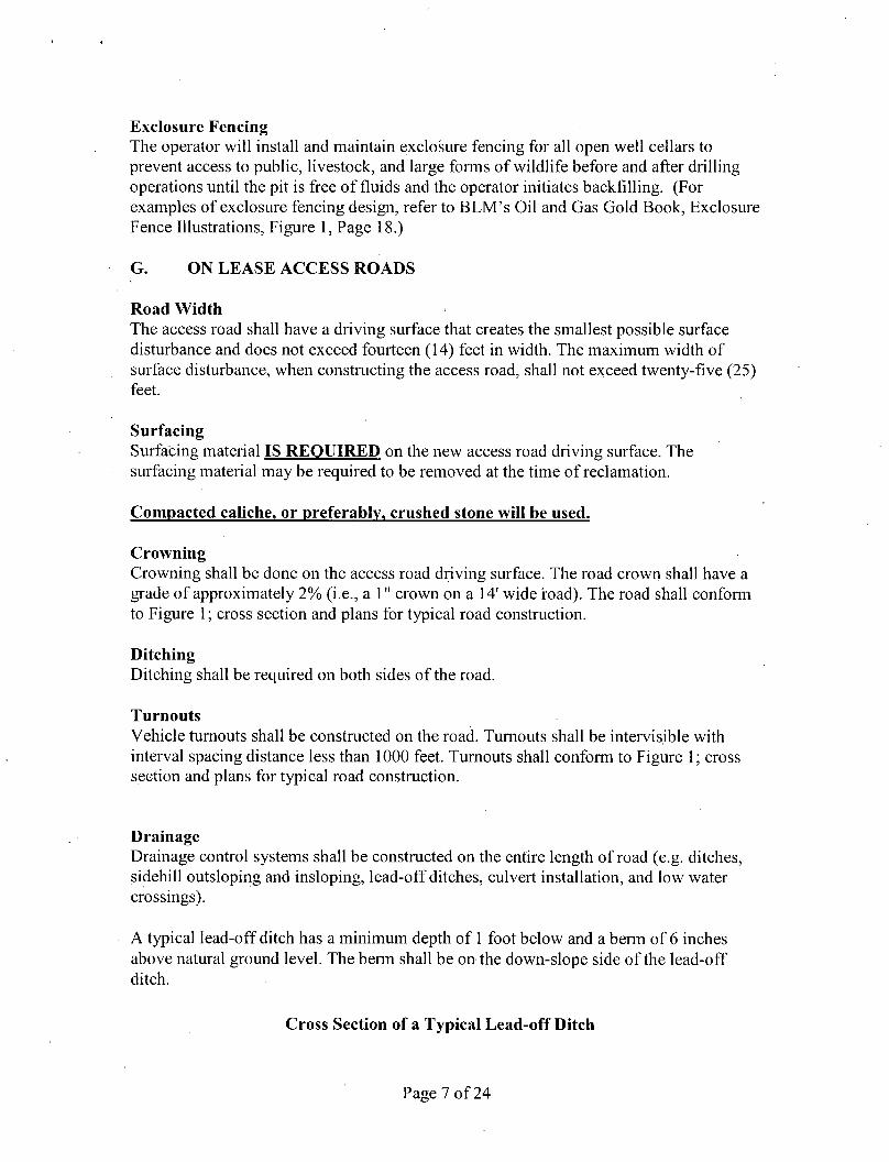
Exclosure Fencing The operator will install and maintain exclosure fencing for all open well cellars to prevent access to public, livestock, and large forms of wildlife before and after drilling operations until the pit is free of fluids and the operator initiates backfilling. (For examples of exclosure fencing design, refer to BLM's Oil and Gas Gold Book, Exclosure Fence Illustrations, Figure 1, Page 18.)
G. ON LEASE ACCESS ROADS
Road Width The access road shall have a driving surface that creates the smallest possible surface disturbance and does not exceed fourteen (14) feet in width. The maximum width of surface disturbance, when constructing the access road, shall not exceed twenty-five (25) feet.
Surfacing Surfacing material IS REQUIRED on the new access road driving surface. The surfacing material may be required to be removed at the time of reclamation.
Compacted caliche, or preferably, crushed stone will be used.
Crowning Crowning shall be done on the access road driving surface. The road crown shall have a grade of approximately 2% (i.e., a 1" crown on a 14' wide road). The road shall conform to Figure 1; cross section and plans for typical road construction.
Ditching
Ditching shall be required on both sides of the road.
Turnouts Vehicle turnouts shall be constructed on the road. Turnouts shall be intervis.ible with interval spacing distance less than 1000 feet. Turnouts shall conform to Figure 1; cross section and plans for typical road construction.
Drainage Drainage control systems shall be constructed on the entire length of road (e.g. ditches, sidehill outsloping and insloping, lead-off ditches, culvert installation, and low water crossings).
A typical lead-off ditch has a minimum depth of 1 foot below and a berm of 6 inches above natural ground level. The berm shall be on the down-slope side of the lead-off ditch.
Cross Section of a Typical Lead-off Ditch
Page 7 of24

''.iDowhiSkope;* Side
MinimumiDepthfe
Al l lead-off ditches shall be graded to drain water with a 1 percent minimum to 3 percent maximum ditch slope. The spacing interval are variable for lead-off ditches and shall be determined according to the formula for spacing intervals of lead-off ditches, but may be amended depending upon existing soil types and centerline road slope (in % ) ;
Example - On a 4% road slope that is 400 feet long, the water flow shall drain water into a lead-off ditch. Spacing interval shall be determined by the following formula:
400 foot road with 4% road slope: 400' + 100' = 200' lead-off ditch interval 4%
Cattleguards An appropriately sized cattleguard sufficient to carry out the project shall be installed and maintained at fence/road crossings. Any existing cattleguards on the access road route shall be repaired or replaced i f they are damaged or have deteriorated beyond practical use. The operator shall be responsible for the condition of the existing cattleguards that are in place and are utilized during lease operations.
Fence Requirement Where entry is granted across a fence line, the fence shall be braced and tied off on both sides of the passageway prior to cutting. The operator shall notify the private surface landowner or the grazing allotment holder prior to crossing any fences.
Public Access Public access on this road shall not be restricted by the operator without specific written approval granted by the Authorized Officer.
Formula for Spacing Interval of Lead-off Ditches
Page 8 of24

Construction Steps 1. Salvage topsoil 2. Construct road
3, Redistribute topsoi! 4. Revegetate slopes
center line of roadway -
shoulder—^ turnout 10'
transition 25' 100' 25" transition full turnout width
Typical Turnout Plan
Iniervisibte turnouts shall be constructed on all single lane roads on all blind cuives with additional runouts as needed to keep spacing below 1 GOO feet
Level Ground Section
Typical Outsloped Section Typical Inslope Section
Figure 1. Cross-sections and plans for typical road sections representative of BLM resource or FS local and higher-class roads.
Page 9 of24

VIII. DRILLING
A. DRILLING OPERATIONS REQUIREMENTS
The BLM is to be notified in advance for a representative to witness:
a. Spudding well (minimum of 24 hours) b. Setting and/or Cementing of all casing strings (minimum of 4 hours) c. BOPE tests (minimum of 4 hours)
Eddy County Call the Carlsbad Field Office, 620 East Greene St., Carlsbad, NM 88220, (575)361-2822
1. Although Hydrogen Sulfide has not been reported in the area, it is always a potential hazard. If Hydrogen Sulfide is encountered, report measured amounts and formations to the BLM.
2. Unless the production casing has been run and cemented or the well has been properly plugged, the drilling rig shall not be removed from over the hole without prior approval. If the drilling rig is removed without approval - an Incident of Non-Compliance will be written and will be a "Major" violation.
3. Floor controls are required for 3M or Greater systems. These controls will be on the rig floor, unobstructed, readily accessible to the driller and will be operational at all times during drilling and/or completion activities. Rig floor is defined as the area immediately around the rotary table; the area immediately above the substructure on which the draw works is located, this does not include the dog house or stairway area.
4. The record of the drilling rate along with the GR/N well log run from TD to surface (horizontal well - vertical portion of hole) shall be submitted to the BLM office as well as all other logs run on the borehole 30 days from completion. If available, a digital copy of the logs is to be submitted in addition to the paper copies. The top and bottom of Salt are to be recorded on the Completion Report.
B. CASING
Changes to the approved APD casing program need prior approval if the items substituted are of lesser grade or different casing size. The Operator can exchange the components of the proposal with that of superior strength (i.e. changing from J-55 to N-80, or from 36# to 40#). Changes to the approved cement program need prior approval if the altered cement plan has less volume or strength or if the changes are substantial (i.e. Multistage tool, ECP, etc.).
Page 10 of 24

Centralizers required on surface casing per Onshore Order 2.III.B.l.f.
Wait on cement (WOC) time prior to drilling out for a primary cement job will be a minimum 18 hours for a water basin, 24 hours in the potash area, or 500 pounds compressive strength, whichever is greater for all casing strings. DURING THIS WOC TIME, NO DRILL PIPE, ETC. SHALL BE RUN IN THE HOLE. Provide compressive strengths including hours to reach required 500 pounds compressive strength prior to cementing each casing string. IF OPERATOR DOES NOT HAVE THE WELL SPECIFIC CEMENT DETAILS ONSITE PRIOR TO PUMPING THE CEMENT FOR EACH CASING STRING, THE WOC WILL BE 30 HOURS. See individual casing strings for details regarding lead cement slurry requirements.
No pea gravel permitted for remedial or fall back remedial without prior authorization from the BLM engineer. Possible water flows in the Castile and Delaware. Possible lost circulation in the Salado, Delaware, and Bone Spring.
HIGH CAVE/KARST - A MINIMUM OF TWO CASING STRINGS CEMENTED TO SURFACE IS REQUIRED IN HIGH CAVE/KARST AREAS. THE CEMENT MUST BE IN A SOLID SHEATH. THEREFORE, ONE INCH OPERATIONS ARE NOT SUFFICIENT TO PROTECT CAVE KARST RESOURCES. A CASING DESIGN THAT HAS A ONE INCH JOB PERFORMED DOES NOT COUNT AS A SOLID SHEATH.
1. The 13-3/8 inch surface casing shall be set at approximately 450 feet (a minimum of 25 feet into the Rustler Anhydrite and above the salt) and cemented to the surface. If salt is encountered, set casing at least 25 feet above the salt.
a. If cement does not circulate to the surface, the appropriate BLM office shall be notified and a temperature survey utilizing an electronic type temperature survey with surface log readout will be used or a cement bond log shall be run to verify the top of the cement. Temperature survey will be run a minimum of six hours after pumping cement and ideally between 8-10 hours after completing the cement job.
b. Wait on cement (WOC) time for a primary cement job is to include the lead cement slurry.
c. Wait on cement (WOC) time for a remedial job will be a minimum of 4 hours after bringing cement to surface or 500 pounds compressive strength, whichever is greater.
d. If cement falls back, remedial cementing will be done prior to drilling out that string. 1
Page 11 of 24

2. The minimum required fill of cement behind the 9-5/8 inch intermediate casing, which shall be set at approximately 6850 feet, is:
Operator has proposed DV tool at a depth of 1900'. Operator is to submit sundry if DV tool depth varies by more than 100' from approved depth.
a. First stage to DV tool:
E Cement to circulate. If cement does not circulate, contact the appropriate BLM office before proceeding with second stage cement job. Operator should have plans as to how they will achieve circulation on the next stage.
b. Second stage above DV tool:
E Cement to surface. If cement does not circulate see B.l.a, c-d above. Wait on cement (WOC) time for a primary cement job is to include the lead cement slurry due to cave/karst.
Pilot hole plugging procedure is approved as written.
3. The minimum required fill of cement behind the 5-1/2 inch production casing is:
E] Cement should tie-back at least 200 feet into previous casing string. Operator shall provide method of verification.
4. If hardband drill pipe is rotated inside casing, returns will be monitored for metal. If metal is found in samples, drill pipe will be pulled and rubber protectors which have a larger diameter than the tool joints of the drill pipe will be installed prior to continuing drilling operations.
C. PRESSURE CONTROL
1. All blowout preventer (BOP) and related equipment (BOPE) shall comply with well control requirements as described in Onshore Oil and Gas Order No. 2 and API RP 53 Sec. 17.
2. Variance approved to use flex line from BOP to choke manifold. Check condition of flexible line from BOP to choke manifold, replace if exterior is damaged or if line fails test. Line to be as straight as possible with no hard bends and is to be anchored according to Manufacturer's requirements. The flexible hose can be exchanged with a hose of equal size and equal or greater pressure rating. Anchor requirements, specification sheet and hydrostatic pressure test certification matching the hose in service, to be onsite for review. These documents shall be posted in the company man's trailer and on the rig floor. If the BLM inspector questions the straightness of the hose, a BLM engineer will be contacted and will review in the
Page 12 of24
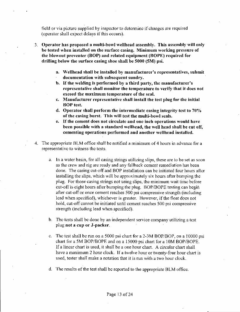
field or via picture supplied by inspector to determine if changes are required (operator shall expect delays i f this occurs).
3. Operator has proposed a multi-bowl wellhead assembly. This assembly will only be tested when installed on the surface casing. Minimum working pressure of the blowout preventer (BOP) and related equipment (BOPE) required for drilling below the surface casing shoe shall be 5000 (5M) psi.
a. Wellhead shall be installed by manufacturer's representatives, submit documentation with subsequent sundry.
b. If the welding is performed by a third party, the manufacturer's representative shall monitor the temperature to verify that it does not exceed the maximum temperature of the seal.
c. Manufacturer representative shall install the test plug for the initial BOP test.
d. Operator shall perform the intermediate casing integrity test to 70% of the casing burst. This will test the multi-bowl seals.
e. If the cement does not circulate and one inch operations would have been possible with a standard wellhead, the well head shall be cut off, cementing operations performed and another wellhead installed.
4. The appropriate BLM office shall be notified a minimum of 4 hours in advance for a representative to witness the tests.
a. In a water basin, for all casing strings utilizing slips, these are to be set as soon as the crew and rig are ready and any fallback cement remediation has been done. The casing cut-off and BOP installation can be initiated four hours after installing the slips, which will be approximately six hours after bumping the plug. For those casing strings not using slips, the minimum wait time before cut-off is eight hours after bumping the plug. BOP/BOPE testing can begin after cut-off or once cement reaches 500 psi compressive strength (including lead when specified), whichever is greater. However, i f the float does not hold, cut-off cannot be initiated until cement reaches 500 psi compressive strength (including lead when specified).
b. The tests shall be done by an independent service company utilizing a test plug not a cup or J-packer.
c. The test shall be run on a 5000 psi chart for a 2-3M BOP/BOP, on a 10000 psi chart for a 5M BOP/BOPE and on a 15000 psi chart for a 10M BOP/BOPE. If a linear chart is used, it shall be a one hour chart. A circular chart shall have a maximum 2 hour clock. If a twelve hour or twenty-four hour chart is used, tester shall make a notation that it is run with a two hour clock.
d. The results of the test shall be reported to the appropriate BLM office.
Page 13 of 24

e. All tests are required to be recorded on a calibrated test chart. A copy of the BOP/BOPE test chart and a copy of independent service company test will be submitted to the appropriate BLM office.
f. The BOP/BOPE test shall include a low pressure test from 250 to 3OQ psi. . The test will be held for a minimum of 10 minutes if test is done with a test plug and 30 minutes without a test plug. This test shall be perfonned prior to the test at full stack pressure.
D. DRILL STEM TEST
If drill stem tests are perfonned, Onshore Order 2.III.D shall be followed.
E. WASTE MATERIAL AND FLUIDS
All waste (i.e. drilling fluids, trash, salts, chemicals, sewage, gray water, etc.) created as a result of drilling operations and completion operations shall be safely contained and disposed of properly at a waste disposal facility. No waste material or fluid shall be disposed of on the well location or surrounding area.
Porto-johns and trash containers will be on-location during fracturing operations or any other crew-intensive operations.
CRW 121914
Page 14 of 24

IX. PRODUCTION (POST DRILLING)
A. WELL STRUCTURES & FACILITIES
Placement of Production Facilities Production facilities should be placed on the well pad to allow for maximum interim recontouring and revegetation of the well location.
Exclosure Netting (Open-top Tanks) Immediately following active drilling or completion operations, the operator will take actions necessary to prevent wildlife and livestock access, including avian wildlife, to all open-topped tanks that contain or have the potential to contain salinity sufficient to cause harm to wildlife or livestock, hydrocarbons, or Resource Conservation and Recovery Act of 1976-exempt hazardous substances. At a minimum, the operator will net, screen, or cover open-topped tanks to exclude wildlife and livestock and prevent mortality. If the operator uses netting, the operator will cover and secure the open portion of the tank to prevent wildlife entry. The operator will net, screen, or cover the tanks until the operator removes the tanks from the location or the tanks no longer contain substances that could be harmful to wildlife or livestock. Use a maximum netting mesh size of 1 lA inches. The netting must not be in contact with fluids and must not have holes or gaps.
Chemical and Fuel Secondary Containment and Exclosure Screening The operator will prevent all hazardous, poisonous, flammable, and toxic substances from coming into contact with soil and water. At a minimum, the operator will install and maintain an impervious secondary containment system for any tank or barrel containing hazardous, poisonous, flammable, or toxic substances sufficient to contain the contents of the tank or barrel and any drips, leaks, and anticipated precipitation. The operator will dispose of fluids within the containment system that do not meet applicable state or U. S. Environmental Protection Agency livestock water standards in accordance with state law; the operator must not drain the fluids to the soil or ground. The operator will design, construct, and maintain all secondary containment systems to prevent wildlife and livestock* exposure to harmful substances. At a minimum, the operator will install effective wildlife and livestock exclosure systems such as fencing, netting, expanded metal mesh, lids, and grate covers. Use a maximum netting mesh size of 1 V2 inches.
Open-Vent Exhaust Stack Exclosures The operator will construct, modify, equip, and maintain all open-vent exhaust stacks on production equipment to prevent birds and bats from entering, and to discourage perching, roosting, and nesting. {Recommended exclosure structures on open-vent exhaust stacks are in the shape of a cone.) Production equipment includes, but may not be limited to, tanks, heater-treaters, separators, dehydrators, flare stacks, in-line units, and compressor mufflers.
Containment Structures Proposed production facilities such as storage tanks and other vessels will have a secondary containment structure that is constructed to hold the capacity of 1.5 times the
Page 15 of 24

largest tank, plus freeboard to account for precipitation, unless more stringent protective requirements are deemed necessary.
Painting Requirement All above-ground structures including meter housing that are not subject to safety requirements shall be painted a flat non-reflective paint color, Shale Green from the BLM Standard Environmental Color Chart (CC-001: June 2008).
B. PIPELINES The holder shall indemnify the United States against any liability for damage to life or property arising from the occupancy or use of public lands under this grant.
2. The holder shall comply with all applicable Federal laws and regulations existing or hereafter enacted or promulgated. In any event, the holder shall comply with the Toxic Substances Control Act of 1976 as amended, 15 USC 2601 et seg- (1982) with regards to any toxic substances that are used, generated by or stored on the right-of-way or on facilities authorized under this right-of-way grant. (See 40 CFR, Part 702-799 and especially, provisions on polychlorinated biphenyls, 40 CFR 761.1 -761.193.) Additionally, any release of toxic substances (leaks, spills, etc.) in excess of the reportable quantity established by 40 CFR, Part 117 shall be reported as required by the Comprehensive Environmental Response, Compensation, and Liability Act, section 102b. A copy of any report required or requested by any Federal agency or State government as a result of a reportable release or spill of any toxic substances shall be furnished to the authorized officer concurrent with the filing of the reports to the involved Federal agency or State government.
3. The holder agrees to indemnify the United States against any liability arising from the release of any hazardous substance or hazardous waste (as these terms are defined in the Comprehensive Environmental Response, Compensation and'Liability Act of 1980, 42 U.S.C. 9601, et seq. or the Resource Conservation and Recovery Act, 42 U.S.C. 6901, et seq.) on the Right-ofrWay (unless the release or threatened release is wholly unrelated to activity of the Right-of-Way holder's activity on the Right-of-Way), or resulting from the activity of the Right-of-Way holder on the Right-of-Way. This agreement applies without regard to whether a release is caused by the holder, its agent, or unrelated third parties.
4. The holder shall be liable for damage or injury to the United States to the extent provided by 43 CFR Sec. 2883.1-4. The holder shall be held to a standard of strict liability for damage or injury to the United States resulting from pipe rupture, fire, or spills caused or substantially aggravated by any of the following within the right-of-way or permit area:
a. Activities of the holder including, but not limited to construction, operation, maintenance, and termination of the facility.
b. Activities of other parties including, but not limited to: (1) Land clearing.
Page 16 of 24

(2) Earth-disturbing and earth-moving work. (3) Blasting. (4) Vandalism and sabotage,
c. Acts of God.
The maximum limitation for such strict liability damages shall not exceed one million dollars ($1,000,000) for any one event, and any liability in excess of such amount shall be determined by the ordinary rules of negligence of the jurisdiction in which the damage or injury occurred.
This section shall not impose strict liability for damage or injury resulting primarily from an act of war or from the negligent acts or omissions of the United States.
5. If, during any phase of the construction, operation, maintenance, or termination of the pipeline, any oil, salt water, or other pollutant should be discharged from the pipeline system, impacting Federal lands, the control and total removal, disposal, and cleaning up of such oil, salt water, or other pollutant, wherever found, shall be the responsibility of the holder, regardless of fault. Upon failure of the holder to control, dispose of, or clean up such discharge on or affecting Federal lands, or to repair all damages resulting therefrom, on the Federal lands, the Authorized Officer may take such measures as he deems necessary to control and clean up the discharge and restore the area, including, where appropriate, the aquatic environment and fish and wildlife habitats, at the full expense of the holder. Such action by the Authorized Officer shall not relieve the holder of any responsibility as provided herein.
6. All construction and maintenance activity will be confined to the authorized right-of-way width of 20 feet. If the pipeline route follows an existing road or buried pipeline right-of-way, the surface pipeline must be installed no farther than 10 feet from the edge of the road or buried pipeline right-of-way. If existing surface pipelines ' prevent this distance, the proposed surface pipeline must be installed immediately adjacent to the outer surface pipeline. All construction and maintenance activity will be confined to existing roads or right-of-ways.
7. No blading or clearing of any vegetation will be allowed unless approved in writing by the Authorized Officer.
8. The holder shall install the pipeline on the surface in such a manner that will minimize suspension of the pipeline across low areas in the terrain: In hummocky of duney areas, the pipeline will be "snaked" around hummocks and dunes rather then suspended across these features.
9. The pipeline shall be buried with a minimum of 24 inches under all roads, "two-tracks," and trails. Burial of the pipe will continue for 20 feet on each side of each crossing. The condition of the road, upon completion of construction, shall be returned to at least its former state with no bumps or dips remaining in the road surface.
Page 17 of24

10. The holder shall minimize disturbance to existing fences and other improvements on public lands. The holder is required to promptly repair improvements to at least their former state. Functional use of these improvements will be maintained at all times. The holder will contact the owner of any improvements prior to disturbing them. When necessary to pass through a fence line, the fence shall be braced on both sides of the passageway prior to cutting of the fence. No permanent gates will be allowed unless approved by the Authorized Officer.
11. In those areas where erosion control structures are required to stabilize soil conditions, the holder will install such structures as are suitable for the specific soil conditions being encountered and which are in accordance with sound resource management practices.
12. Excluding the.pipe, all above-ground structures not subject to safety requirement shall be painted by the holder to blend with the natural color of the landscape. The paint used shall be a color which simulates "Standard Environmental Colors" - Shale Green, Munsell Soil Color No. 5Y 4/2; designated by the Rocky Mountain Five State Interagency Committee.
13. The pipeline will be identified by. signs at the point of origin and completion of the right-of-way and at all road crossings. At a minimum, signs will state the holder's name, BLM serial number, and the product being transported. Signs will be maintained in a legible condition for the life of the pipeline.
14. The holder shall not use the pipeline route as a road for purposes other than routine maintenance as determined necessary by the Authorized Officer in consultation with the holder. The holder will take whatever steps are necessary to ensure that the pipeline route is not used as a roadway.
15. Any cultural and/or paleontological resource (historic or prehistoric site or object) discovered by the holder, or any person working on his behalf, on public or Federal land shall be immediately reported to the authorized officer. Holder shall suspend all operations in the immediate area of such discovery until written authorization to proceed is issued by the authorized officer. An evaluation of the discovery will be made by the authorized officer to determine appropriate cultural or scientific values. The holder will be responsible for the cost of evaluation and any decision as to proper mitigation measures will be made by the authorized officer after consulting with the holder.
•
16. The operator shall be held responsible i f noxious weeds become established within the areas of operations. Weed control shall be required on the disturbed land where noxious weeds exist, which includes'the roads, powerline corridor, and adjacent land affected by the establishment of weeds due to this action. The operator shall consult with the Authorized Officer for acceptable weed control methods, which include following EPA and BLM requirements and policies.
Page 18 of 24

17. Surface pipelines must be less than or equal to 4 inches and a working pressure below 125 psi.
C. FRAC POND The Holder shall indemnify the United States against any liability for damage to life or property arising from the occupancy or use of public lands under this permit.
2. The Holder shall comply with all applicable Federal laws and regulations existing or hereafter enacted or promulgated.
3. Required Standard Conditions of Approval:
a. Notification Contact the Supervisory Environmental Protection Specialist, Jim Amos, at 575-234-5909 at least 24 hours prior to starting construction.
b. Freshwater Only The frac pond will only be authorized to contain freshwater and testing of water quality is required. Additives are not allowed without consent of the authorized officer in writing.
c. Contamination If at any time the water in the frac pond becomes polluted with salts or other contaminants, use of the frac pond will cease and desist, and all liquids will be removed from the frac pond and disposed of properly. The operator will preclude releases of oil into open pits. The operator must remove any accumulation of oil, condensate, or contaminant in a pit within 48 hours of discovery.
d. Authorized Disturbance Confine all construction and maintenance activity to the approved authorized area applied for in the application.
e. Facilities Porto-johns and trash containers will be on-location during fracturing operations or any other crew-intensive operations. Grey-water, sewage, and trash shall be removed from .the site and disposed of properly at a state approved facility.
f. Escape Ramps The operator will construct and maintain frac ponds to prevent livestock, wildlife, and humans from becoming entrapped. At a minimum, the operator will construct and maintain escape ramps, ladders, or other methods of avian and terrestrial wildlife escape in frac ponds. Escape ramps must be installed at every corner of the frac pond and in the center of each side i f that side exceeds 100 feet in length. Escape ramps must be in contact with the side of the frac pond, bottom of the frac pond, and the top of the frac pond berm. Escape ramps cannot be made of metal and cannot be steeper than a 3:1 slope (Horizontal Distance: Vertical Distance) or
Page 19 of 24

30% slope. {Examples of escape ramps: 12 " wide wooden planks wrapped in matting, felt lining, etc.)
g. Frac Pond Pipelines Temporary pipelines flowing from the frac pond to the target well will be laid along existing roadways unless an exception has been granted by the authorized officer in writing.
h. Mineral Material from Excavation Mineral materials extracted during construction of the frac pond will be stored on-location and/or used for constructing the frac pond.
i. Frac Pond Liner The frac pond will be lined with at least a 30 mil. plastic liner. The plastic lining will be removed prior to final abandonment.
j . Topsoil Stockpile The operator shall strip at least the top 6 inches of soil (root zone) from the entire frac pond area and stockpile the topsoil approximately 25 feet outside the bermed perimeter of the pond in a low profile manner, reasonably protected from wind and water erosion. Topsoil shall not be used for constructing the frac pond. The topsoil will be used for final reclamation purposes only.
k. Frac Pond Fence The operator will install and maintain exclosure fencing on all sides of the frac pond to prevent access to public, livestock, and large forms of wildlife. The fence shall be installed at the base of the berm and never on top of the berm. Construction of the fence shall consist of steel and/or wooden posts set firmly into natural ground. Hog panel or chain-link fencing must be used as the fence and tied securely to the fence posts. Barbed-wire fencing or electric fences shall not be used. The fence height shall not be shorter than six (6) feet. The erected fence shall be maintained in adequate condition until the frac pond is reclaimed.
1. Erosion Prevention Install earthen erosion-control structures as are suitable for the specific terrain and soil conditions.
m. Reclamation Start I . Reclamation efforts will commence immediately after the frac pond is no
longer needed for the purpose of completing wells. II. Within 3 months of completion of frac operations on associated wells, all
earthwork and final reclamation must be completed. This includes reclaiming and/or removal of:
i . Any roads approved for'use with the pond ii . Surface water lines
iii . Tanks, pumps, fencing etc.
Requirements for Operations and Final Reclamation:
Page 20 of 24

4. If, during any phase of the construction, operation, maintenance, or termination of the frac pond, any pollutant should be released from the contaminated frac pond, the control and total removal, disposal, and cleaning up of such pollutant, wherever found, shall be the responsibility of holder, regardless of fault.
Upon failure of holder to control, dispose of, or clean up such discharge, or to repair all damages resulting there-from, the Authorized Officer may take such measures as he deems necessary to control and clean up the discharge and restore the area, including where appropriate, the aquatic environment and fish and wildlife habitats, at the full expense of the holder. Such action by the Authorized Officer shall not relieve holder of any responsibility as provided herein.
5. Any cultural and/or paleontological resources (historic or prehistoric site or object) discovered by the holder, or any person working on his behalf shall be immediately reported to the Authorized Officer. Holder shall suspend all operations in the immediate area of such discovery until written authorization to proceed is issued by the Authorized Officer. An evaluation of the discovery will be made by the Authorized Officer to determine appropriate actions to prevent the loss of significant cultural or scientific values. The holder will be responsible for the cost of evaluation and any decision as to proper mitigation measures will be made by the Authorized Officer after consulting with the holder.
6. The operator shall be held responsible i f noxious weeds become established within the areas of operations. Weed control shall be required on the disturbed land where noxious weeds exist, which includes the roads, pads, associated pipeline corridor, and adjacent land affected by the establishment of weeds due to this action. The operator shall consult with the Authorized Officer for acceptable weed control methods, which include following EPA and BLM requirements and policies.
7. After all disturbed areas have been satisfactorily contoured and prepared for seeding the location needs to be revegetated with the seed mixture provided. Seeding may need to be repeated until revegetation is successful. Operators shall contact Jim Amos, Supervisor, Environmental Protection - (575)234-5909, prior to beginning surface reclamation operations.
D. FRAC TEMPORY LINES Maintain a copy of your temporary permit and your approved route diagram on location. BLM personnel may request to see a copy of your permit during construction to ensure compliance with all conditions of approval.
Holder agrees to comply with the following conditions of approval to the satisfaction of the Authorized Officer:
Page 21 of 24

1. The Holder shall indemnify the United States against any liability for damage to life or property arising from the occupancy or use of public lands under this permit.
2. Standard Conditions of Approval:
o Pipelines must be removed within 30-45 days from this route unless granted in writing by the authorized officer.
© Pipelines will be placed not farther than 5 to 10 feet off the edge of existing oil and gas maintained roads or other maintained roads,
o Areas impacted (disturbed greater than vegetation compaction) by your project will require full reclamation.
© Pipelines will be empty before disassembly. Flow water back to the designated holding area.
o Do not restrict traffic on existing roads. Place ramps where needed on existing access roads.
© All pumps and other equipment must be placed on existing surfaced areas (pads, roads, etc.).
3. Any cultural and/or paleontological resources (historic or prehistoric site or object) discovered by the holder, or any person working on his behalf shall be immediately reported to the Authorized Officer. Holder shall suspend all operations in the immediate area of such discovery until written authorization to proceed is issued by the Authorized Officer.
4. Special Stipulations:
If the pipeline route is approved to cross open country, the pipe will be hand-carried and hand-laid along the approved route.
X. INTERIM RECLAMATION
During the life of the development, all disturbed areas not needed for active support of production operations should undergo interim reclamation in order to minimize the environmental impacts of development on other resources and uses.
Within six (6) months of well completion, operators should work with BLM surface management specialists (Jim Amos: 575-234-5909) to devise the best strategies to reduce the size of the location. Interim reclamation should allow for remedial well operations, as well as safe and efficient removal of oil and gas.
During reclamation, the removal of caliche is important to increasing the success of revegetating the site. Removed caliche that is free of contaminants may be used for road
Page 22 of 24.
repairs, fire walls or for building other roads and locations. In order to operate the well or complete workover operations, it may be necessary to drive, park and operate on restored interim vegetation within the previously disturbed area. Disturbing revegetated areas for production or workover operations will be allowed: If there is significant disturbance and loss of vegetation, the area will need to be revegetated. Communicate with the appropriate BLM office for any exceptions/exemptions if needed.
All disturbed areas after they have been satisfactorily prepared need to be reseeded with the seed mixture provided below.
Upon completion of interim reclamation, the operator shall submit a Sundry Notices and Reports on Wells, Subsequent Report of Reclamation (Form 3160-5).
X. FINAL ABANDONMENT & RECLAMATION
At final abandonment, well locations, production facilities, and access roads must undergo "final" reclamation so that the character and productivity of the land are restored.
Earthwork for final reclamation must be completed within six (6) months of well plugging. All pads, pits, facility locations and roads must be reclaimed to a satisfactory revegetated, safe, and stable condition, unless an agreement is made with the landowner or BLM to keep the road and/or pad intact.
After all disturbed areas have been satisfactorily prepared, these areas need to be revegetated with the seed mixture provided below. Seeding should be accomplished by drilling on the contour whenever practical or by other approved methods. Seeding may need to be repeated until revegetation is successful, as determined by the BLM.
Operators shall contact a BLM surface protection specialist prior to surface abandonment operations for site specific objectives (Jim Amos: 575-234-5909).
Page 23 of 24

Seed Mixture 4, for Gypsum Sites
The holder shall seed all disturbed areas with the seed mixture listed below. The seed mixture shall be planted in the amounts specified in pounds of pure live seed (PLS)* per acre. There shall be no primary or secondary noxious weeds in the seed mixture. Seed will be tested and the viability testing of seed will be done in accordance with State law(s) and within nine (9) months prior to purchase. Commercial seed will be either certified or registered seed. The seed container will be tagged in accordance with State law(s) and available for inspection by the authorized officer.
Seed will be planted using a drill equipped with a depth regulator to ensure proper depth of planting where drilling is possible. The seed mixture will be evenly and uniformly planted over the disturbed area (smaller/heavier seeds have a tendency to drop the bottom of the drill and are planted first). The holder shall take appropriate measures to ensure this does not occur. Where drilling is not possible, seed will be broadcast and the area shall be raked or chained to cover the seed. When broadcasting the seed, the pounds per acre are to be doubled. The seeding will be repeated until a satisfactory stand is established as determined by the authorized officer. Evaluation of growth will not be: made before completion of at least one full growing season after seeding.
Species to be planted in pounds of pure live seed* per acre:
Species v lb/acre
Alkali Sacaton (Sporobolus airoides) 1.0 DWS Four-wing saltbush (Atriplex canescens). 5.0
DWS: DeWinged Seed
*Pounds of pure live seed:
Pounds of seed x percent purity x percent germination = pounds pure live, seed (Insert Seed Mixture Here)
Page 24 of 24