Security Policy - SpectraGuard Sensor C75 - C75E - …dwd h[lwv wkh 0rgxoh yld wkh 1hwzrun ,qwhuidfh...
30
© 2015 and 2016 Mojo Networks, Inc. This document may be freely reproduced and distributed in whole without any modification. FIPS 140-2 SECURITY POLICY FOR AIRTIGHT WIRELESS SENSOR April 07, 2016
Transcript of Security Policy - SpectraGuard Sensor C75 - C75E - …dwd h[lwv wkh 0rgxoh yld wkh 1hwzrun ,qwhuidfh...

© 2015 and 2016 Mojo Networks, Inc. This document may be freely reproduced and distributed in whole without any modification.
FIPS 140-2 SECURITY POLICY FOR AIRTIGHT WIRELESS SENSOR
April 07, 2016

© 2015 and 2016 Mojo Networks, Inc. This document may be freely reproduced and distributed in whole without any modification. Page 2 of 30
1. Introduction
This document describes the Security Policy for Sensor cryptographic module from Mojo Networks, Inc. The Security Policy specifies the rules under which the module shall operate to meet Federal Information Processing Standard (FIPS) 140-2 Level 2 requirements. FIPS 140-2, Security Requirements for Cryptographic Modules, describes the requirements for cryptographic modules. For more information about the FIPS 140-2 standard and the cryptographic module validation process see http://csrc.nist.gov/groups/STM/cmvp/index.html. 2. Module Specification
This security policy pertains to the Sensor cryptographic module from Mojo Networks, Inc. The hardware versions are C-75 (which exhibits internal antennas) and C-75-E (which exhibits external antennas). Barring the antenna differences, the two hardware versions have identical hardware components and identical firmware. The firmware version is 7.2.FIPS.04. Any of the hardware version C-75 or C-75-E with firmware version 7.2.FIPS.04 is called as the Module in this document. The Module is multi-chip standalone cryptographic module. The Module contains following hardware components: System Processor, Wireless Subsystem, RAM, Flash Memory, Ethernet Network Interface which is POE (Power over Ethernet) capable, Console Interface, LED Interface, Power Inlet, and Pin-hole Reset Button. The physical embodiments of the Module are shown in Figure 1(A) and 1(B) for the C-75 version and the C-75-E version, respectively.

© 2015 and 2016 Mojo Networks, Inc. This document may be freely reproduced and distributed in whole without any modification. Page 3 of 30
Figure 1(A)

© 2015 and 2016 Mojo Networks, Inc. This document may be freely reproduced and distributed in whole without any modification. Page 4 of 30
Figure 1(B)
Figure 2 shows cryptographic boundary for the Module and paths of data, control and status information flow across the cryptographic boundary for the C-75 version and the C-75-E version, respectively.

© 2015 and 2016 Mojo Networks, Inc. This document may be freely reproduced and distributed in whole without any modification. Page 5 of 30
Cryptographic Boundary (C-75)
RAM
Flash
Power Inlet Console Interface LEDs
Wireless Subsystem
NetworkInterface with
POE
System Processor
Pin-holeReset Button
InternalAntenna
Data PathControl and Status Path
Figure 2(A)
Cryptographic Boundary (C-75-E)
RAM
Flash
Power Inlet Console Interface LEDs
Wireless Subsystem
NetworkInterface with
POE
System Processor
Pin-holeReset Button
ExternalAntenna Port
Data PathControl and Status Path
Figure 2(B)

© 2015 and 2016 Mojo Networks, Inc. This document may be freely reproduced and distributed in whole without any modification. Page 6 of 30
The Module has limited operational environment. The firmware executes on a Linux operating system. Access to the operating system operations is restricted. Key components of the firmware include Command Line Interface (CLI) Application which is responsible for providing services to the User of the Module, Secure Shell (SSH) Server which facilitates access to the CLI Application for remote User, Sensor Application which is responsible for core intrusion detection function of the Module, and Cryptographic Libraries which are used to perform various cryptographic functions in the Module. In its operation, the Module scans wireless signals using either internal or external antennas. The Module also sniffs traffic on the wired Network Interface to perform correlation between wired and wireless traffic. The Module transmits wireless signals through antennas to perform functions such as probing wireless devices and to disable undesirable wireless communications. The Module also transmits probing packets and packets to disable undesirable communications over the wired Network Interface. The Module reports wireless scanning and wired sniffing information to the Server and is also able to accept commands from the Server for its operation. By virtue of these operations, the Module ensures that wireless communication activity in its proximity complies with the specified security rules. Ports and Interfaces Physical ports on the Module and their mapping to FIPS 140-2 logical interfaces are shown in the table below.
Physical Port FIPS 140-2 Logical Interface Network Interface Data input, data output, control input, status output,
power (POE). Console Interface Data output, control input, status output. Power Inlet DC power enters via power inlet. It can also enter

© 2015 and 2016 Mojo Networks, Inc. This document may be freely reproduced and distributed in whole without any modification. Page 7 of 30
via the Network Interface which is POE (Power Over Ethernet) capable.
LEDs Status output. Antennas Data input, data output. Pin-hole Reset Button Control input. USB Port Disabled, NA
Logical Interfaces Description of logical interfaces on the Module is provided below.
Data Input Data enters the Module via the antennas (internal or
external). This data represents wireless transmissions detected in the wireless neighborhood of the antennas. Data enters the Module via the Network Interface. This data represents subset of packets traversing the subnet(s) to which the Module’s Network Interface is connected.
Data Output Data exits the Module via the antennas (internal or external). This data represents one or more of (i) wireless-side probing information, and (ii) transmissions used to disable certain wireless communications. Data exits the Module via the Network Interface. This data represents one or more of (i) reports about the wireless transmissions detected in the wireless neighborhood of the antennas, (ii) reports about the devices detected on the subnet(s) to which the Module’s Network Interface is connected, (iii) wire-side probing information, (iv) transmissions used to block certain communications associated with devices on the subnet(s) where the

© 2015 and 2016 Mojo Networks, Inc. This document may be freely reproduced and distributed in whole without any modification. Page 8 of 30
Network Interface is connected. Data also exits the Module via the Console Interface. This data represents (i) reports about the wireless transmissions detected in the wireless neighborhood of the antennas, (ii) reports about the devices detected on the subnet(s) to which the Module’s Network Interface is connected.
Control Input Control input enters the Module via the Network Interface or the Console Interface. This input comprises of information such as network settings, Server discovery settings, status requests, password change, key change, mode change, configuration for wireless scanning, instructions to take actions on specific devices such as probing, disabling etc. Control input to reset the Module to factory settings can also enter via the Pin-Hole Reset Button.
Status Output Status output exits the Module via the Network Interface or the Console Interface. This output comprises of information such as network settings, version number, operation logs, results of self tests, mode of operation, and status of other configuration parameters. Status output can also exit the Sensor via the LED Interface. This Status output consists of information such as whether the Module is powered up, status of the Module’s connectivity to the Server, status of the Wireless Subsystem etc.

© 2015 and 2016 Mojo Networks, Inc. This document may be freely reproduced and distributed in whole without any modification. Page 9 of 30
On any physical port (wherever appropriate) output (data and status) is logically separated from input (data and control) by way of direction of information flow. Data output is logically separated from status output by way of networking protocols and application level identifiers. Data input is logically separated from control input by way of networking protocols and application level identifiers. Modes of Operation The Module is able to operate in FIPS (FIPS compliant) and non-FIPS (not compliant with FIPS) modes. Factory default setting is non-FIPS mode. User of the Module has to turn the Module into FIPS mode, whenever FIPS compliant operation is desired. Specific steps to turn the Module into FIPS mode are as follows:
User logs into the Module over CLI (Command Line Interface). CLI login can be over console cable or SSH
User invokes the “change mode” service by executing the “set FIPS mode” command to turn on the FIPS mode (after this command is executed, the Module reboots and the shared secret key (K) with Server is reset to factory default)
Manually enters the new shared secret key (K) for secure communication with the Server using “set communication key” command.
Whether the Module is running in FIPS mode or not can be checked by the User by running “get FIPS mode” command over CLI. In order to turn the Module that is operating in FIPS mode to non-FIPS mode, following steps are required:
User logs into the Module over CLI User invokes the “change mode” service by executing the “set FIPS
mode” command to turn off the FIPS mode (after this command is executed, the Module reboots and the shared secret key (K) with Server is reset to factory default)

© 2015 and 2016 Mojo Networks, Inc. This document may be freely reproduced and distributed in whole without any modification. Page 10 of 30
Manually enters the new shared secret key (K) for secure communication with the Server using “set communication key” command.
Compliance with FIPS Requirements The Module meets FIPS 140-2 security requirements as follows. Security Requirements Section Level Cryptographic Module Specification 2 Cryptographic Module Ports and Interfaces 2 Roles, Services, and Authentication 2 Finite State Model 2 Physical Security 2 Operational Environment N/A Cryptographic Key Management 2 Electromagnetic Interference/Electromagnetic Compatibility 2 Self Tests 2 Design Assurance 2 Mitigation of Other Attacks Not applicable 3. Security Functions
The various security functions incorporated in the Module are described below. a) Roles, Authentication, Services The Module supports User and Crypto Officer roles. The User can access the Module over the Console Interface or the Network Interface. The Crypto Officer role is assumed by the Server when the Module connects to the Server. User Role

© 2015 and 2016 Mojo Networks, Inc. This document may be freely reproduced and distributed in whole without any modification. Page 11 of 30
The User accesses the Module over the Console Interface (using console wire) or the Network Interface. Information flowing in the console wire is plaintext. Access over the Network Interface is over SSH. User is authenticated to the Module using a password. Password should be at least 6 characters in length. The maximum password length is limited to 32 characters. This results in at least 308,915,776 combinations for the password (computed as 26 raised to the power 6). Thus the possibility of correctly guessing the password is less than 1 in 1,000,000. The login attempt rate of the User is limited to 1 attempt every 3 seconds. In other words, there can be at most 20 login attempts per minute. This in combination with total possible combinations of the password ensures that multiple attempts to use the authentication mechanism during a one-minute period have probability of success less than one in 100,000. When the Module is power cycled, the User will have to re-authenticate. That is, the authentication state is forgotten after power cycle. When the Module is reset to factory default, the password for the User defaults to factory setting. The User password is not reset upon entering or exiting FIPS mode. Crypto Officer can change User password when the Module is properly connected to the Server. Crypto Officer Role Server assumes the role of Crypto Officer when the Module connects to it. The Crypto officer accesses the Module over the 128 bit AES-CBC encrypted tunnel. The Crypto Officer authenticates to the Module using a shared secret key (referred herein as key K) which is 128 bit in length. Since there are 2128 combinations for the key, the possibility of correctly guessing the key is less than 1 in 1,000,000. The key K is manually entered in the Module by the User. Crypto Officer can change the key K when the Module is properly connected to the Server.

© 2015 and 2016 Mojo Networks, Inc. This document may be freely reproduced and distributed in whole without any modification. Page 12 of 30
The authentication is mutual authentication between the Module and the Server using challenge/response procedure. Each side sends a random challenge to the other side. The other side encrypts the challenge with key K using AES-CBC encryption and sends encrypted response to the issuing side. The issuing side decrypts the response to verify that originally issued challenge is found therein. The authentication attempt rate is limited to 1 attempt every 2 minutes. When the Module is power cycled, the Crypto Officer will have to re-authenticate. That is, the authentication state is forgotten after power cycle. When the Module is reset to factory default, the shared secret key K defaults to factory setting. It will also be reset to factory default (zeroized) upon entering and exiting the FIPS mode of operation for the Module. The following table summarizes strength of authentication for User and Crypto Officer roles. Role Auth.
Credentials Minimum Length
Maximum Length
Strength per Attempt
Strength per Minute
User Password 6 characters
Unrestricted Probability of success less than 1 in 308,915,776
Probability of success less than 1 in 15,445,788
Crypto Officer
Key 128 bits 128 bits Probability of success is 1 in 2128
Probability of success is 1 in 2128
The services available to the User and the Crypto Officer are shown in the table below. Service User Crypto
Officer Description

© 2015 and 2016 Mojo Networks, Inc. This document may be freely reproduced and distributed in whole without any modification. Page 13 of 30
Login Yes No Log into the Module to access CLI (Command Line Interface).
Operational settings Yes Yes Configure operational settings such as network settings, wireless settings etc.
Change mode Yes No Change mode of operation of the Module between FIPS and non-FIPS.
Change shared secret key (K)
Yes Yes Change shared secret key (K) used between the Module and the Server.
Change User password Yes Yes Change password used to authenticate the User.
View self test result Yes No Check result of self tests. Perform on-demand self test (same as Reboot)
Yes Yes Perform self tests/reboot the Module.
Reset factory defaults (same as Zeroize)
Yes No Restore the Module to factory default state.
Show status Yes Yes View status of operation of the Module.
b) Controlling Access to the Module for the First time When the User turns the Module into FIPS mode, the User is required to change the shared secret key (K) from its factory default value. The User is required to put tamper resistant labels on the Module before installation. The User should also change the password from factory default value. c) Encryption/Decryption

© 2015 and 2016 Mojo Networks, Inc. This document may be freely reproduced and distributed in whole without any modification. Page 14 of 30
Various encryption/decryption functions are described below: c.1) Communication with Server Certain data output going out of the Network Interface of the Module and directed to the Server is encrypted. The control input from Server (Server commands) is also encrypted, and so is the status output from the Module to the Server. Derivation and Transport of Session Key (SK) After successful mutual authentication, the session key (SK) is randomly generated by the Server and transported to the Module. The message carrying SK from the Server to the Module is encrypted by the key K using AES-CBC encryption and authenticated via HMAC-SHA-1 by the key K. The session key is 128 bits in length. Derivation of Message Encryption and Authentication Keys (MAK, MEK) The message encryption key (MEK) and message authentication key (MAK) are derived via HMAC-SHA-1 of predetermined text using the session key SK as the secret key. The MEK is 128 bits in length and the MAK is 160 bits in length. The MAK is used for per-message HMAC-SHA-1 authentication and the MEK is used for per-message AES-CBC encryption between the Module and the Server. There is different pair of (MAK, MEK) in each direction – Module to Server and Server to Module. These key derivation procedures are in compliance with NIST Special Publication 800-108, Recommendation for Key Derivation Using Pseudorandom Functions, October 2009. Shared Secret Key (K) Management After the User turns the Module into FIPS mode, the User is required to change the K from its factory default setting. The key K resets to factory default (zeroized) upon entering or existing the FIPS mode. The User has to manually input the new value of key K in the Module. During such times as the Module is properly connected to the Server, the shared secret key (K) can be electronically changed by the Server. The new key travels from the Server to the Module within a message that is protected via AES encryption and HMAC-SHA-1 authentication

© 2015 and 2016 Mojo Networks, Inc. This document may be freely reproduced and distributed in whole without any modification. Page 15 of 30
with the key SK. The User is required to zeroize the shared secret key either by resetting the module to factory default or by exiting the FIPS mode at such times as the Module is to be discarded. The plaintext key K is never outputted from the Module. c.2) Data Output via Antennas Payload of some wireless-side probing information transmitted from antennas is encrypted using 128 bit AES-CBC encryption using the MEK (from Module to Server) described above. c.3) SSH Server SSH server is used to support remote access for the User role. In FIPS mode, it uses following cryptographic algorithms: RSA (2048 bits) for host authentication, Diffie-Helman for key agreement (using Oakley DH Group 14 which uses a public key of size 2048 bits), AES-CBC for encryption, and HMAC-SHA-1 for message integrity. The SSH server authenticates the client using password. The RSA public/private key pair for host authentication is randomly generated when the module is first booted, and thereafter on entering or exiting FIPS mode, or on reset to factory defaults. The Diffie-Hellman key agreement messages described below are digitally signed with RSA private key by the SSH Server. The RSA private key is never output from the Module. The Diffie-Hellman key agreement procedure is used to first arrive at a common key between the SSH Server and the SSH Client. The common key is then used to derive message authentication key (160 bits long) and message encryption key (128 bits long) for the SSH session. The message authentication key is used for HMAC-SHA-1 integrity protection and the message encryption key is AES-CBC message encryption for messages sent in SSH session. d) Summary of Passwords, Keys and Critical Security Parameters (CSPs) Passwords, keys and CSPs used in the Module are summarized below, along with access control to them. The “read” access (“R”) means ability to read value,

© 2015 and 2016 Mojo Networks, Inc. This document may be freely reproduced and distributed in whole without any modification. Page 16 of 30
the “write” (“W”) access means ability to change value (including zeroization/reset to factory default and deletion), and the “execute” (“E”) access means ability to use value for performing some function in obtaining a specific service. Password/ Key/ CSP
Description Access to Password (U: User, CO: Crypto Officer; Access right denoted in parentheses)
User Password Used to authenticate the User. Password should be at least 6 characters in length. The User password may be shared between non-FIPS and FIPS modes. The password is stored in hashed form in non-volatile memory.
“Change User password” service: U (W), CO (W). “Reset factory defaults” service: U (W). “Login” service: U (E).
Shared Secret Key (K)
Used for mutual authentication with the Server. This key is 128 bits in length. It cannot be shared between non-FIPS and FIPS modes. This key is stored in plaintext in non-volatile memory, and is zeroized (reset to factory default) upon entering/exiting FIPS mode or reset to factory default. The key K is never output from the Module.
“Change shared secret key (K)” service: U (W), CO (W). “Change mode” and “Reset to factory defaults” services: U (W).
Session key The key SK is used to derive “Reboot” service: U (W), CO (W).

© 2015 and 2016 Mojo Networks, Inc. This document may be freely reproduced and distributed in whole without any modification. Page 17 of 30
(SK)
encryption and authentication key pairs (MEK, MAK) for communication between the Module and the Server. The key SK is 128 bits in length and it cannot be shared between non-FIPS and FIPS modes. It is stored in plaintext in volatile memory. It is deleted upon termination of the session between the Module and the Server, power cycle, reboot, entering/exiting FIPS mode, or reset to factory default. The key SK is never output from the Module.
“Change mode” and “Reset to factory defaults” services: U (W).
Outbound and Inbound Message Authentication Keys (MAKs)
The key MAK is used for authentication of messages between the Module and the Server. There is a different key MAK in outbound and inbound direction. Each key MAK is 160 bits in length. These keys cannot be shared between non-FIPS and FIPS modes. They are stored in plaintext in volatile memory, and are deleted upon termination of the session between the Module and the Server, power cycle, reboot,
“Device settings”, “Change shared secret key (K)”, “Change User password”, “Reboot”, and “Show status” services: CO (E). “Reboot” service: U (W), CO (W). “Change mode” and “Reset to factory defaults” services: U (W).

© 2015 and 2016 Mojo Networks, Inc. This document may be freely reproduced and distributed in whole without any modification. Page 18 of 30
entering/exiting FIPS mode, or reset to factory default. These keys are never output from the Module.
Outbound and Inbound Message Encryption Keys (MEKs)
The key MEK is used for encryption of messages between the Module and the Server. There is a different key MEK in outbound and inbound direction. Each key MEK is 128 bits in length. These keys cannot be shared between non-FIPS and FIPS modes. They are stored in plaintext in volatile memory, and are deleted upon termination of the session between the Module and the Server, power cycle, reboot, entering/exiting FIPS mode, or reset to factory default. These keys are never output from the Module.
“Device settings”, “Change shared secret key (K)”, “Change User password”, “Reboot”, and “Show status” services: CO (E). “Reboot” service: U (W), CO (W). “Change mode” and “Reset to factory defaults” services: U (W).
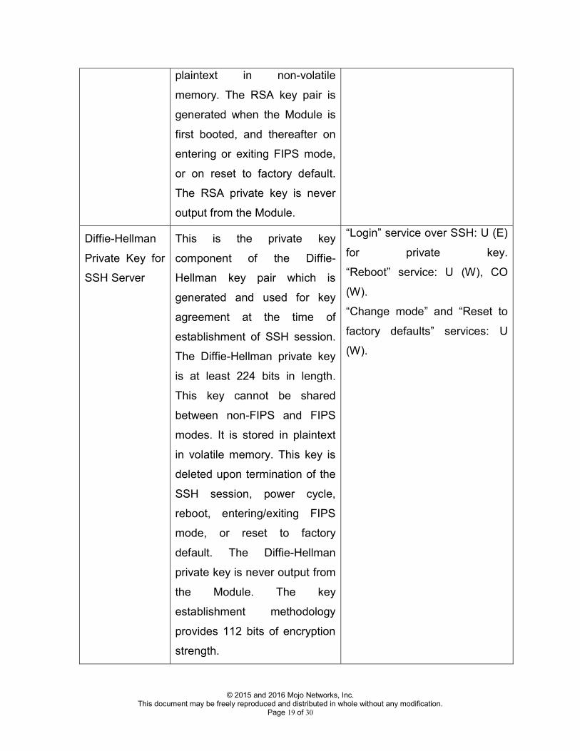
RSA Private Key for SSH Server
This is the private key component of the RSA key pair which is used for host authentication in SSH. The RSA private key is 2048 bits in length. It cannot be shared between non-FIPS and FIPS modes. This key is stored in
“Login” service over SSH: U (E) for private key. “Change mode” and “Reset to factory defaults” services: U (W).
© 2015 and 2016 Mojo Networks, Inc. This document may be freely reproduced and distributed in whole without any modification. Page 19 of 30
plaintext in non-volatile memory. The RSA key pair is generated when the Module is first booted, and thereafter on entering or exiting FIPS mode, or on reset to factory default. The RSA private key is never output from the Module.
Diffie-Hellman Private Key for SSH Server
This is the private key component of the Diffie-Hellman key pair which is generated and used for key agreement at the time of establishment of SSH session. The Diffie-Hellman private key is at least 224 bits in length. This key cannot be shared between non-FIPS and FIPS modes. It is stored in plaintext in volatile memory. This key is deleted upon termination of the SSH session, power cycle, reboot, entering/exiting FIPS mode, or reset to factory default. The Diffie-Hellman private key is never output from the Module. The key establishment methodology provides 112 bits of encryption strength.
“Login” service over SSH: U (E) for private key. “Reboot” service: U (W), CO (W). “Change mode” and “Reset to factory defaults” services: U (W).

© 2015 and 2016 Mojo Networks, Inc. This document may be freely reproduced and distributed in whole without any modification. Page 20 of 30
SSH per-session message authentication keys (outbound and inbound)
There is one 160-bit key for message authentication in each direction in the SSH session. These keys cannot be shared between non-FIPS and FIPS modes. They are stored in plaintext in volatile memory. These keys are generated at the time of SSH session establishment. They are deleted upon termination of the SSH session, power cycle, reboot, entering/exiting FIPS mode, or reset to factory default. These keys are never output from the Module.
All User services when obtained over SSH: U (E). “Reboot” service: U (W), CO (W). “Change mode” and “Reset to factory defaults” services: U (W).
SSH per-session message encryption keys (outbound and inbound)
There is one 128-bit key for message encryption in each direction in the SSH session. These keys cannot be shared between non-FIPS and FIPS modes. They are stored in plaintext in volatile memory. These keys are generated at the time of SSH session establishment. They are deleted upon termination of the SSH session, power cycle, reboot, entering/exiting FIPS mode, or reset to factory
All User services when obtained over SSH: U (E). “Reboot” service: U (W), CO (W). “Change mode” and “Reset to factory defaults” services: U (W).

© 2015 and 2016 Mojo Networks, Inc. This document may be freely reproduced and distributed in whole without any modification. Page 21 of 30
default. These keys are never output from the Module.
Seed and Nonce for DRBG (Deterministic Random Bit Generator)
DRBG takes 256-bit random seed and 128-bit random nonce for random number generation. Seed and nonce are obtained by reading bytes from the /dev/random device and feeding them directly to DRBG. Seed and nonce cannot be shared between non-FIPS and FIPS modes. The seed and the nonce are stored in volatile memory in plaintext. They are deleted from memory on power cycle, reboot, entering/exiting FIPS mode, or reset to factory default. Seed and nonce are never output from the Module.
“Reboot” service: U (W), CO (W). “Change mode” and “Reset to factory defaults” services: U (W).
Preserved state of LRNG (Linux Random Number Generator)
LRNG maintains entropy pool of 512 bytes. When new samples of noise are received, they are mixed into this pool. Entropy can be extracted from this pool via /dev/random and /dev/urandom. At the time of system shutdown, the Module extracts 512 bytes from the pool via /dev/urandom and
“Reboot” service: U (W), CO (W). “Change mode” and “Reset to factory defaults” services: U (W).

© 2015 and 2016 Mojo Networks, Inc. This document may be freely reproduced and distributed in whole without any modification. Page 22 of 30
stores them in non-volatile memory in plaintext. At the time of system start, the stored 512 bytes are mixed into the entropy pool. The stored 512 bytes are deleted upon entering/exiting the FIPS mode or reset to factory default. They cannot be shared between FIPS and non-FIPS mode. They are never output from the Module.
Public Keys: The following public keys are used in the Module in FIPS mode:
o RSA Public Key for SSH Server (2048 bits): It is the public key counterpart of the private key used for host authentication in SSH. It cannot be shared between non-FIPS and FIPS modes. This key is stored in plaintext in non-volatile memory. The RSA key pair is generated when the Module is first booted, and thereafter on entering or exiting FIPS mode, or on reset to factory default. It is output from the Module to the SSH client, when the client attempts connection to the SSH server in the Module.
o Diffie-Hellman Public Key for SSH Server (2048 bits): It is the public key component of the private key used for key agreement at the time of establishment of SSH session. It cannot be shared between non-FIPS and FIPS modes. This key is stored in plaintext in volatile memory. It is deleted upon termination of the SSH session, power cycle, reboot, entering/exiting FIPS mode, or reset to factory default. It is output from the Module to the

© 2015 and 2016 Mojo Networks, Inc. This document may be freely reproduced and distributed in whole without any modification. Page 23 of 30
SSH client, when the client attempts connection to the SSH server in the Module.
Additional Keys: The following additional keys are used in FIPS mode. They are not considered CSPs.
o When a new User password is set by the Crypto Officer through the Sensor-Server communication tunnel, in addition to the AES message encryption key (MEK) used to protect all data sent through the tunnel, the new password is also ciphered by a fixed factory-defined 128 bit AES key. This factory-defined ciphering key cannot be changed or zeroized. For FIPS 140-2 purposes, this additional ciphering is considered equivalent to plaintext.
o Some wire-side probing information contains ciphered information which is considered equivalent to plaintext. The keys used for this ciphering process are derived using proprietary techniques.
e) Summary of Cryptographic Algorithms The Module implements the following FIPS approved or allowed algorithms.
Algorithm Validation Certificate
Firmware Version
Usage Keys/CSPs AES 3766 7.2.FIPS.04 Encrypt/decrypt Shared secret key
(K), message encryption key (MEK), SSH per-session message encryption key
SHA-1 3135 7.2.FIPS.04 Hashing None HMAC-SHA-1 2465 7.2.FIPS.04 Message
integrity, key derivation
Shared secret key (K), session key (SK), message authentication key (MAK), SSH per-session message authentication

© 2015 and 2016 Mojo Networks, Inc. This document may be freely reproduced and distributed in whole without any modification. Page 24 of 30
key, firmware upgrade key
RSA 1937 7.2.FIPS.04 Digital signature RSA private key DRBG (AES CTR)
1036 7.2.FIPS.04 Random number generation
Key and V KBKDF 77 7.2.FIPS.04 Key derivation Session key (SK) CVL (SSH KDF) 710 7.2.FIPS.04 Key derivation SSH per-session
message authentication and encryption keys
Diffie-Hellman
Non-approved, but allowed
7.2.FIPS.04 Key establishment
Diffie-Hellman keys
NDRNG Non-approved, but allowed
7.2.FIPS.04 Linux random number generator (LRNG)
State of entropy pool
MD5 Non-approved, but allowed
7.2.FIPS.04 Boot time firmware integrity check
None
It is to be noted that the SSH KDF has been validated by the CAVP, but SSH protocol has not been reviewed or tested by the CAVP and CMVP. The module also implements the following algorithms for ciphering of certain information (which is considered equivalent to plaintext) mentioned above.
Algorithm Usage Keys AES Cipher/de-cipher Password ciphering key and
probing information ciphering key
The same cryptographic algorithms are used in FIPS and non-FIPS modes. However, their keys/CSPs are not shared between FIPS and non-FIPS modes. 4. Self Tests

© 2015 and 2016 Mojo Networks, Inc. This document may be freely reproduced and distributed in whole without any modification. Page 25 of 30
The Module always reboots when FIPS mode is entered. At boot time, firmware integrity check is done using MD5 checksum of the firmware. Algorithm Test MD5 Firmware integrity If the firmware integrity test passes, the Module performs following power-up self tests: Algorithm Test AES Encrypt KAT AES Decrypt KAT RSA Sign KAT RSA Verify KAT DRBG KAT HMAC-SHA-1 KAT SHA-1 KAT If any of the above tests fails, the Module goes to the Error State. During operation, the module performs following conditional self tests: Algorithm Test RSA Pairwise consistency DRBG Continuous NDRNG (/dev/random)
Continuous
If conditional test for RSA or DRBG fails, the Module enters the Error State. If conditional test for NDRNG fails, the module discards the output of /dev/random that causes the test to fail.

© 2015 and 2016 Mojo Networks, Inc. This document may be freely reproduced and distributed in whole without any modification. Page 26 of 30
In the Error State, the Module does not output any data on the Data Output interface. The results of the above tests can be viewed by the User by accessing the Module over the Console Interface. When the User attempts changing the shared secret key (K), manual key entry test is performed. If the test succeeds, new key is accepted. Else, new key is rejected. Algorithm Test Manual key entry It is also possible to perform on-demand self test by rebooting the Module. 5. Physical Security The Module is made from production-grade components, which are encased within an opaque, hard, production-grade enclosure. The Module meets commercial-grade specifications for power, temperature, reliability, shock and vibration. Tamper resistant labels The tamper labels shall be applied for the Module to operate in a FIPS approved mode of operation as shown in the following Figures 3(A), 4(A) and 5(A) for the version C-75, and Figures 3(B), 4(B) and 5(B) for the version C-75-E. Before applying the labels, it is recommended to clean the surface of the Module which will receive the labels with dry cloth or tissue paper. The Module must be periodically inspected by the User for evidence of tampering, at least once every three months. If tampering is suspected, the Module must be disconnected from network, reset to factory default and securely stored for forensic analysis.

© 2015 and 2016 Mojo Networks, Inc. This document may be freely reproduced and distributed in whole without any modification. Page 27 of 30
Customers can order the tamper resistant labels from the vendor (part number C-TPL-A). User is responsible for securing and having control at all times of any unused labels.
Figure 3(A)

© 2015 and 2016 Mojo Networks, Inc. This document may be freely reproduced and distributed in whole without any modification. Page 28 of 30
Figure 3(B)
Figure 4(A)

© 2015 and 2016 Mojo Networks, Inc. This document may be freely reproduced and distributed in whole without any modification. Page 29 of 30
Figure 4(B)
Figure 5(A)

© 2015 and 2016 Mojo Networks, Inc. This document may be freely reproduced and distributed in whole without any modification. Page 30 of 30
Figure 5(B)