1 HFR - TAG High Availability Ravi Narayanan ([email protected]) Ravi Narayanan ([email protected])
Cisco SystemsCopyright © 2000 Cisco Systems, Inc. All Rights Reserved.
Page i
W
HITE
P
APER
Cisco SAFE: A
Security
Blueprint
for
Enterprise
Networks
TABLE OF CONTENTS
Authors . . . . . . . . . . . . . . . . . . . . . . . . . . . . . . . . . 1
Abstract . . . . . . . . . . . . . . . . . . . . . . . . . . . . . . . . . 1
Audience . . . . . . . . . . . . . . . . . . . . . . . . . . . . . . . . 2
Caveats . . . . . . . . . . . . . . . . . . . . . . . . . . . . . . . . . 2
Architecture Overview . . . . . . . . . . . . . . . . . . . . . . 3
Design Fundamentals . . . . . . . . . . . . . . . . . . . . . . . . . . . 3
Module Concept . . . . . . . . . . . . . . . . . . . . . . . . . . . . . . . 3
SAFE Axioms . . . . . . . . . . . . . . . . . . . . . . . . . . . . . . . . . 5
Enterprise Module . . . . . . . . . . . . . . . . . . . . . . . . . . 9
Expected Threats . . . . . . . . . . . . . . . . . . . . . . . . . . . . . . 9
Enterprise Campus . . . . . . . . . . . . . . . . . . . . . . . . .10
Management Module . . . . . . . . . . . . . . . . . . . . . . . . . . 11
Core Module . . . . . . . . . . . . . . . . . . . . . . . . . . . . . . . . . 15
Building Distribution Module . . . . . . . . . . . . . . . . . . . . 15
Building Module . . . . . . . . . . . . . . . . . . . . . . . . . . . . . . 17
Server Module . . . . . . . . . . . . . . . . . . . . . . . . . . . . . . . 18
Edge Distribution Module . . . . . . . . . . . . . . . . . . . . . . . 19
Enterprise Edge . . . . . . . . . . . . . . . . . . . . . . . . . . .22
Corporate Internet Module . . . . . . . . . . . . . . . . . . . . . . 24
VPN and Remote Access Module . . . . . . . . . . . . . . . . . 28
WAN Module . . . . . . . . . . . . . . . . . . . . . . . . . . . . . . . . . 32
E-Commerce Module . . . . . . . . . . . . . . . . . . . . . . . . . . . 33
Enterprise Options . . . . . . . . . . . . . . . . . . . . . . . . . . . . 36

Cisco SystemsCopyright © 2000 Cisco Systems, Inc. All Rights Reserved.
Page ii
Migration Strategies . . . . . . . . . . . . . . . . . . . . . . . . 37
Appendix A: Validation Lab . . . . . . . . . . . . . . . . . . . 37
Overall Guidelines . . . . . . . . . . . . . . . . . . . . . . . . . . . . 37
Management Module . . . . . . . . . . . . . . . . . . . . . . . . . . 41
Core Module . . . . . . . . . . . . . . . . . . . . . . . . . . . . . . . . . 44
Building Distribution Module . . . . . . . . . . . . . . . . . . . . 44
Building Access Module . . . . . . . . . . . . . . . . . . . . . . . . 46
Edge Distribution Module . . . . . . . . . . . . . . . . . . . . . . 48
Corporate Internet Module . . . . . . . . . . . . . . . . . . . . . 48
VPN and Remote Access Module . . . . . . . . . . . . . . . . . 51
WAN Module . . . . . . . . . . . . . . . . . . . . . . . . . . . . . . . . 54
Appendix B: Network Security Primer . . . . . . . . . . . 55
The Need for Network Security . . . . . . . . . . . . . . . . . . 55
Network Attack Taxonomy . . . . . . . . . . . . . . . . . . . . . . 55
What Is a “Security Policy”? . . . . . . . . . . . . . . . . . . . . 62
The Need for a Security Policy . . . . . . . . . . . . . . . . . . . 62
Appendix C: Architecture Taxonomy . . . . . . . . . . . . 62
Diagram Legend . . . . . . . . . . . . . . . . . . . . . . . . . . . . . . 63
References . . . . . . . . . . . . . . . . . . . . . . . . . . . . . . . 64
RFCs . . . . . . . . . . . . . . . . . . . . . . . . . . . . . . . . . . . . . . . 64
Miscellaneous References . . . . . . . . . . . . . . . . . . . . . . 64
Partner Product References . . . . . . . . . . . . . . . . . . . . . 64
Acknowledgments . . . . . . . . . . . . . . . . . . . . . . . . . 64

Copyr
WHITE PAPER
Cisco SAFE: A Security Blueprint for
Enterprise Networks
Authors
Sean Convery (CCIE #4232) and Bernie Trudel (CCIE #1884) are the authors of this White Paper. Sean is the
lead architect for the reference implementation of this architecture at Cisco’s headquarters in San Jose, CA
USA. Sean and Bernie are both members of the VPN and Security Architecture Technical Marketing team in
Cisco’s Enterprise Line of Business.
Abstract
The principle goal of Cisco’s secure blueprint for enterprise networks (SAFE) is to provide best practice
information to interested parties on designing and implementing secure networks. SAFE serves as a guide to
network designers considering the security requirements of their network. SAFE takes a defense-in-depth
approach to network security design. This type of design focuses on the expected threats and their methods
of mitigation, rather than on “Put the firewall here, put the intrusion detection system there.” This strategy
results in a layered approach to security where the failure of one security system is not likely to lead to the
compromise of network resources. SAFE is based on Cisco products and those of its partners.
This document begins with an overview of the architecture, then details the specific modules that make up
the actual network design. The first three sections of each module describe the traffic flows, key devices, and
expected threats with basic mitigation diagrams. Detailed technical analysis of the design follows, along with
more detailed threat mitigation techniques and migration strategies. Appendix A details the validation lab for
SAFE and includes configuration snapshots. Appendix B is a primer on network security. Readers who are
unfamiliar with basic network security concepts are encouraged to read this section before the rest of the
document. Appendix C contains glossary definitions of the technical terms used in this document and a legend
for the included figures.
This document focuses heavily on threats encountered in enterprise environments. Network designers who
understand these threats can better decide where and how to deploy mitigation technologies. Without a full
understanding of the threats involved in network security, deployments tend to be incorrectly configured, are
too focused on security devices, or lack threat response options. By taking the threat-mitigation approach,
this document should provide network designers with information for making sound network security
choices.
Cisco Systemsight © 2000 Cisco Systems, Inc. All Rights Reserved.
Page 1 of 65

Audience
Though this document is technical in nature, it can be read at different levels of detail, depending on the reader. A network
manager, for example, can read the introductory sections in each area to obtain a good overview of network security design
strategies and considerations. A network engineer or designer can read this document in its entirety and gain design
information and threat analysis details, which are supported by configuration snapshots for the devices involved.
Caveats
This document presumes that you already have a security policy in place. Cisco Systems does not recommend deploying
security technologies without an associated policy. This document directly addresses the needs of large enterprise customers.
While most of the principles discussed here also apply directly to small and medium businesses, and even home offices, they
do so on a different scale. A detailed analysis of these business types is outside the scope of this document. However, in order
to address the issue of smaller-scale networks in a limited manner, the “Alternatives” and “Enterprise Options” sections
outline devices that you can eliminate if you want to reduce the cost of the architecture.
Following the guidelines in this document does not guarantee a secure environment, or that you will prevent all intrusions.
True absolute security can only be achieved by disconnecting a system from the network, encasing it in concrete, and putting
it in the bottom floor of Fort Knox. Your data will be very safe, though inaccessible. However, you can achieve reasonable
security by establishing a good security policy, following the guidelines in this document, staying up to date on the latest
developments in the hacker and security communities, and maintaining and monitoring all systems with sound system
administration practices. This includes awareness of application security issues that are not comprehensively addressed in
this paper.
Though virtual private networks (VPNs) are included in this architecture, they are not described in great detail. Information
such as scaling details, resilience strategies, and other topics related to VPNs are not included. Like VPNs, identity strategies
(including certificate authorities [CAs]) are not discussed at any level of detail in this paper. Similarly, CAs require a level of
focus that this document could not provide and still adequately address all the other relevant areas of network security. Also,
because most enterprise networks have yet to deploy fully functional CA environments, it is important to discuss how to
securely deploy networks without them. Finally, certain advanced networked applications and technologies (such as content
networking, caching, and server load balancing) are not included in this document. Although their use within SAFE is to be
expected, this paper does not cover their specific security needs.
SAFE uses the products of Cisco Systems and its partners. However, this document does not specifically refer to products by
name. Instead, components are referred to by functional purpose rather than model number or name. During the validation
of SAFE, real products were configured in the exact network implementation described in this document. Specific
configuration snapshots from the lab are included in Appendix A, “Validation Lab.”
Throughout this document the term “hacker” denotes an individual who attempts to gain unauthorized access to network
resources with malicious intent. While the term “cracker” is generally regarded as the more accurate word for this type of
individual, hacker is used here for readability.
Cisco SystemsCopyright © 2000 Cisco Systems, Inc. All Rights Reserved.
Page 2 of 65
Architecture Overview
Design Fundamentals
SAFE emulates as closely as possible the functional requirements of today’s enterprise networks. Implementation decisions
varied depending on the network functionality required. However, the following design objectives, listed in order of priority,
guided the decision-making process.
• Security and attack mitigation based on policy
• Security implementation throughout the infrastructure (not just on specialized security devices)
• Secure management and reporting
• Authentication and authorization of users and administrators to critical network resources
• Intrusion detection for critical resources and subnets
• Support for emerging networked applications
First and foremost, SAFE is a security architecture. It must prevent most attacks from successfully affecting valuable network
resources. The attacks that succeed in penetrating the first line of defense, or originate from inside the network, must be
accurately detected and quickly contained to minimize their effect on the rest of the network. However, in being secure, the
network must continue to provide critical services that users expect. Proper network security and good network functionality
can be provided at the same time. The SAFE architecture is not a revolutionary way of designing networks, but merely a
blueprint for making networks secure.
SAFE is also resilient and scalable. Resilience in networks includes physical redundancy to protect against a device failure
whether through misconfiguration, physical failure, or network attack. Although simpler designs are possible, particularly if
a network’s performance needs are not great, this document uses a complex design as an example because designing security
in a complex environment is more involved than in simpler environments. Options to limit the complexity of the design are
discussed throughout this document.
At many points in the network design process, you need to choose between using integrated functionality in a network device
versus using a specialized functional appliance. The integrated functionality is often attractive because you can implement it
on existing equipment, or because the features can interoperate with the rest of the device to provide a better functional
solution. Appliances are often used when the depth of functionality required is very advanced or when performance needs
require using specialized hardware. Make your decisions based on the capacity and functionality of the appliance versus the
integration advantage of the device. For example, sometimes you can chose an integrated higher-capacity Cisco IOS™ router
with IOS firewall software as opposed to a smaller IOS router with a separate firewall. Throughout this architecture, both
types of systems are used. Most critical security functions migrate to dedicated appliances because of the performance
requirements of large enterprise networks.
Module Concept
Although most enterprise networks evolve with the growing IT requirements of the enterprise, the SAFE architecture uses a
green-field modular approach. A modular approach has two main advantages. First, it allows the architecture to address the
security relationship between the various functional blocks of the network. Second, it permits designers to evaluate and
implement security on a module by module basis, instead of attempting the complete architecture in a single phase.
Figure 1 illustrates the first layer of modularity in SAFE. Each block represents a functional area. The Internet service
provider (ISP) module is not implemented by the enterprise, but is included to the extent that specific security features should
be requested of an ISP in order to mitigate against certain attacks.
Cisco SystemsCopyright © 2000 Cisco Systems, Inc. All Rights Reserved.
Page 3 of 65
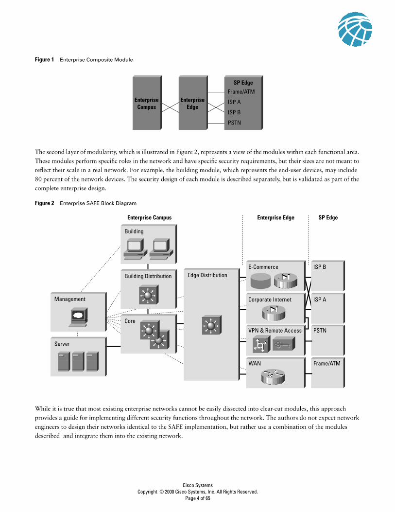
Figure 1 Enterprise Composite Module
The second layer of modularity, which is illustrated in Figure 2, represents a view of the modules within each functional area.
These modules perform specific roles in the network and have specific security requirements, but their sizes are not meant to
reflect their scale in a real network. For example, the building module, which represents the end-user devices, may include
80 percent of the network devices. The security design of each module is described separately, but is validated as part of the
complete enterprise design.
Figure 2 Enterprise SAFE Block Diagram
While it is true that most existing enterprise networks cannot be easily dissected into clear-cut modules, this approach
provides a guide for implementing different security functions throughout the network. The authors do not expect network
engineers to design their networks identical to the SAFE implementation, but rather use a combination of the modules
described and integrate them into the existing network.
EnterpriseCampus
EnterpriseEdge
Frame/ATM
SP Edge
ISP A
ISP B
PSTN
Core
Enterprise Campus Enterprise Edge SP Edge
Building
Building Distribution
Server
Management
Edge Distribution
PSTNVPN & Remote Access
Frame/ATMWAN
ISP BE-Commerce
ISP ACorporate Internet
Cisco SystemsCopyright © 2000 Cisco Systems, Inc. All Rights Reserved.
Page 4 of 65

SAFE Axioms
Routers Are TargetsRouters control access from every network to every network. They advertise networks and filter who can use them, and they
are potentially a hacker’s best friend. Router security is a critical element in any security deployment. By their nature, routers
provide access and, therefore, you should secure them to reduce the likelihood that they are directly compromised. You can
refer to other documents that have been written about router security. These documents provide more detail on the following
subjects:
• Locking down telnet access to a router
• Locking down Simple Network Management Protocol (SNMP) access to a router
• Controlling access to a router through the use of Terminal Access Controller Access Control System Plus (TACACS+)
• Turning off unneeded services
• Logging at appropriate levels
• Authentication of routing updates
The most current document on router security is available at the following URL: http://www.cisco.com/warp/customer/707/
21.html
Switches Are TargetsLike routers, switches (both Layer 2 and Layer 3) have their own set of security considerations. Unlike routers, not as much
public information is available about the security risks in switches and what can be done to mitigate those risks. Most of the
security techniques detailed in the preceding section, “Routers Are Targets,” apply to switches. In addition, you should take
the following precautions:
• Ports without any need to trunk, should have any trunk settings set to off, as opposed to auto. This prevents a host from
becoming a trunk port and receiving all traffic that would normally reside on a trunk port.
• Make sure that trunk ports use a virtual LAN (VLAN) number not used anywhere else in the switch. This prevents packets
tagged with the same VLAN as the trunk port from reaching another VLAN without crossing a Layer 3 device. For more
information, refer to the following URL: http://www.sans.org/newlook/resources/IDFAQ/vlan.htm
• Set all unused ports on a switch to a VLAN that has no Layer 3 connectivity. Better yet, disable any port that is not needed.
This prevents hackers from plugging in to unused ports and communicating with the rest of the network.
• Avoid using VLANs as the sole method of securing access between two subnets. The capability for human error, combined
with understanding that VLANs and VLAN tagging protocols were not designed with security in mind, makes their use in
sensitive environments inadvisable. When VLANs are needed in security deployments, be sure to pay close attention to the
configurations and guidelines mentioned above.
Within an existing VLAN, private VLANs provide some added security to specific network applications. Private VLANs
work by limiting which ports within a VLAN can communicate with other ports in the same VLAN. Isolated ports within a
VLAN can communicate only with promiscuous ports. Community ports can communicate only with other members of the
same community and promiscuous ports. Promiscuous ports can communicate with any port. This is an effective way to
mitigate the effects of a single compromised host. Consider a standard public services segment with a Web, FTP, and Domain
Name System (DNS) server. If the DNS server is compromised, a hacker can pursue the other two hosts without passing back
through the firewall. If private VLANs are deployed, once one system is compromised, it cannot communicate with the other
systems. The only targets a hacker can pursue are hosts on the other side of the firewall.
Cisco SystemsCopyright © 2000 Cisco Systems, Inc. All Rights Reserved.
Page 5 of 65

Hosts Are TargetsA host is the most likely target during an attack and presents some of the most difficult challenges from a security perspective.
There are numerous hardware platforms, operating systems, and applications, all of which have updates, patches, and fixes
available at different times. Because hosts provide the application services to other hosts that request them, they are extremely
visible within the network. For example, many people have visited http://www.whitehouse.gov, which is a host, but few have
attempted to access s2-0.whitehouseisp.net, which is a router. Because of this visibility, hosts are the most frequently attacked
devices in any network intrusion attempt.
In part because of the security challenges mentioned above, hosts are also the most successfully compromised devices. For
example, a given Web server on the Internet might run a hardware platform from one vendor, a network card from another,
an operating system from still another vendor, and a Web server that is either open source or from yet another vendor.
Additionally, the same Web server might run applications that are freely distributed via the Internet, and might communicate
with a database server that starts the variations all over again. That is not to say that the security vulnerabilities are
specifically caused by the multisource nature of all of this, but rather that as the complexity of a system increases, so does
the likelihood of a failure.
To secure hosts, pay careful attention to each of the components within the systems. Keep any systems up to date with the
latest patches, fixes, and so forth. In particular, pay attention to how these patches affect the operation of other system
components. Evaluate all updates on test systems before you implement them in a production environment. Failure to do so
might result in the patch itself causing a denial of service (DoS).
Networks Are TargetsThe worst attack is the one that you cannot stop. When performed properly, distributed denial of service (DDoS) is just such
an attack. As outlined in Appendix B, “Network Security Primer,” DDoS works by causing tens or hundreds of machines to
simultaneously send spurious data to an IP address. The goal of such an attack is generally not to shut down a particular
host, but rather to make the entire network unresponsive. For example, consider an organization with a DS3 (45 Mbps)
connection to the Internet that provides e-commerce services to its Web site users. Such a site is very security conscious and
has intrusion detection, firewalls, logging, and active monitoring. Unfortunately, all these security devices do not help when
a hacker launches a successful DDoS attack.
Consider 100 devices around the world, each with DS1 (1.5 Mbps) connections to the Internet. If these systems are remotely
told to flood the serial interface of the e-commerce organization’s Internet router, they can easily flood the DS3 with
erroneous data. Even if each host is only able to generate 1 Mbps of traffic, (lab tests indicate that a stock Unix workstation
can easily generate 50 Mbps with a popular DDoS tool), that amount is still more than twice the amount of traffic that the
e-commerce site can handle. As a result, legitimate Web requests are lost, and the site appears to be down for most users.
The local firewall drops all the erroneous data, but by then, the damage is done. The traffic has crossed the WAN connection
and filled up the link.
Only through cooperation with their ISP can this fictitious e-commerce company hope to thwart such an attack. An ISP can
configure rate limiting on the outbound interface to the company’s site. This rate limiting can drop most undesired traffic
when it exceeds a prespecified amount of the available bandwidth. The key is to correctly flag traffic as undesired.
Common forms of DDoS attacks are ICMP floods, TCP SYN floods, or UDP floods. In an e-commerce environment, this
type of traffic is fairly easy to categorize. Only when limiting a TCP SYN attack on port 80 (http) does an administrator run
the risk of locking out legitimate users during an attack. Even then, it is better to temporarily lock out new legitimate users
and retain routing and management connections, than to have the router overrun and lose all connectivity.
Cisco SystemsCopyright © 2000 Cisco Systems, Inc. All Rights Reserved.
Page 6 of 65
More sophisticated attacks use port 80 traffic with the ACK bit set so that the traffic appears to be legitimate Web
transactions. It is unlikely that an administrator could properly categorize such an attack because acknowledged TCP
communications are exactly the sort that you want to allow into your network.
One approach to limiting this sort of attack is to follow the guidelines outlined in RFC 1918 and RFC 2827. RFC 1918
specifies the networks that are reserved for private use and should never be seen across the public Internet. RFC 2827
filtering is discussed in the “IP Spoofing” section of Appendix B, “Network Security Primer.” For inbound traffic on a router
that is connected to the Internet, you could employ RFC 1918 and 2827 filtering to prevent unauthorized traffic from
reaching the corporate network. When implemented at the ISP, this filtering prevents DDoS attack packets that use these
addresses as sources from traversing the WAN link, potentially saving bandwidth during the attack. Collectively, if ISPs
worldwide were to implement the guidelines in RFC 2827, source address spoofing would be greatly diminished. While this
strategy does not directly prevent DDoS attacks, it does prevent such attacks from masking their source, which makes
traceback to the attacking networks much easier.
Applications Are TargetsApplications are coded by human beings (mostly) and, as such, are subject to numerous errors. These errors can be
benign—for example, an error that causes your document to print incorrectly—or malignant—for example, an error that
makes the credit card numbers on your database server available via anonymous FTP. It is the malignant problems, as well
as other more general security vulnerabilities, that intrusion detection systems (IDSs) aim to detect. Intrusion detection acts
like an alarm system in the physical world. When an IDS detects something that it considers an attack, it can either take
corrective action itself or notify a management system for actions by the administrator. Some systems are more or less
equipped to respond and prevent such an attack. Host-based intrusion detection can work by intercepting OS and application
calls on an individual host. It can also operate by after-the-fact analysis of local log files. The former approach allows better
attack prevention, while the latter approach dictates a more passive attack response role. Because of the specificity of their
role, host-based IDS (HIDS) systems are often better at preventing specific attacks than Network IDS (NIDS), which usually
only issue an alert upon discovery of an attack. However, that specificity causes a loss of perspective to the overall network.
This is where NIDS excels. Cisco recommends a combination of the two systems—HIDS on critical hosts and NIDS looking
over the whole network—for a complete intrusion detection system.
Once deployed, you must tune an IDS implementation to increase its effectiveness and remove “false-positives.”
False-positives are defined as alarms caused by legitimate traffic or activity. False-negatives are attacks that the IDS system
fails to see. Once the IDS is tuned, you can configure it more specifically as to its threat mitigation role. As was mentioned
above, you should configure HIDS to stop most valid threats at the host level because it is well prepared to determine that
certain activity is indeed a threat.
When deciding on mitigation roles for NIDS there are two primary options:
The first option, and potentially the most damaging if improperly deployed, is to “shun” traffic through the addition of
access control filters on routers. When a NIDS detects an attack from a particular host over a particular protocol, it can block
that host from coming into the network for a predetermined amount of time. While on the surface this might seem like a
great aid to a security administrator, in reality it must be very carefully implemented, if at all. The first problem is that of
spoofed addresses. If traffic that matches an attack is seen by the NIDS, and that particular alarm triggers a shun response,
the NIDS will deploy the access list to the device. However, if the attack that caused the alarm used a spoofed address, the
NIDS has now locked out an address that never initiated an attack. If the IP address that the hacker used happens to be the
IP address of a major ISP’s outbound HTTP proxy server, a huge number of users could be locked out. This by itself could
be an interesting DoS threat in the hands of a creative hacker.
Cisco SystemsCopyright © 2000 Cisco Systems, Inc. All Rights Reserved.
Page 7 of 65

To mitigate the risks of shunning, you should generally use it only on TCP traffic, which is much more difficult to successfully
spoof than UDP. Use it only in cases where the threat is real and the chance of the attack being a false positive is very low.
However, in the interior of a network, many more options exist. With effectively deployed RFC 2827 filtering, spoofed traffic
should be very limited. Also, because customers are not generally on the internal network, you can take a more restrictive
stance against internally originated attack attempts. Another reason for this is that internal networks do not often have the
same level of stateful filtering that edge connections possess. As such, IDS needs to be more heavily relied upon than in the
external environment.
The second option for NIDS threat mitigation is the use of TCP resets. As the name implies, TCP resets operate only on TCP
traffic and terminate an active attack by sending TCP reset messages to the attacking and attacked host. Because TCP traffic
is more difficult to spoof, you should consider using TCP resets more often than shunning.
From a performance standpoint, NIDS observes packets on the wire. If packets are sent faster than the NIDS can process
them, there is no degradation to the network because the NIDS does not sit directly in the flows of data. However, the NIDS
will lose effectiveness and packets could be missed causing both false-negatives and false-positives. Be sure to avoid exceeding
the capabilities of IDS so that you can get their benefit. From a routing standpoint, IDS, like many state-aware engines, does
not operate properly in an asymmetrically routed environment. Packets sent out from one set of routers and switches and
returning through another will cause the IDS systems to see only half of the traffic, causing false-positives and negatives.
Secure Management and Reporting“If you’re going to log it, read it.” So simple a proposition, that almost everyone familiar with network security has said it
at least once. Yet logging and reading information from over 100 devices can prove to be a challenging proposition. Which
logs are most important? How do I separate important messages from mere notifications? How do I ensure that logs are not
tampered with in transit? How do I ensure my time-stamps match each other when multiple devices report the same alarm?
What information is needed if log data is required for a criminal investigation? How do I deal with the volume of messages
that can be generated by a large network? You must address all these questions when considering managing log files
effectively. From a management standpoint, a different set of questions needs to be asked: How do I securely manage a
device? How can I push content out to public servers and ensure that it is not tampered with in transit? How can I track
changes on devices to troubleshoot when attacks or network failures occur?
From an architectural point of view, providing out-of-band management of network systems is the best first step in any
management and reporting strategy. Out-of-band (OOB), as its name implies, refers to a network on which no production
traffic resides. Devices should have a direct local connection to such a network where possible, and where impossible, (due
to geographic, or system-related issues) the device should connect via a private encrypted tunnel over the production
network. Such a tunnel should be preconfigured to communicate only across the specific ports required for management and
reporting. The tunnel should also be locked down so that only appropriate hosts can initiate and terminate tunnels. Be sure
that the out-of-band network does not itself create security issues. See the “Management Module” section of this document
for more details.
After implementing an OOB management network, dealing with logging and reporting becomes more straightforward. Most
networking devices can send syslog data, which can be invaluable when troubleshooting network problems or security
threats. Send this data to one or more syslog analysis hosts on the management network. Depending on the device involved,
you can choose various logging levels to ensure that the correct amount of data is sent to the logging devices. You also need
to flag device log data within the analysis software to permit granular viewing and reporting. For example, during an attack
the log data provided by Layer 2 switches might not be as interesting as the data provided by the intrusion detection system.
Specialized applications, such as IDS, often use their own logging protocols to transmit alarm information. Usually this data
should be logged to separate management hosts that are better equipped to deal with attack alarms. When combined, alarm
data from many different sources can provide information about the overall health of the network. To ensure that log
Cisco SystemsCopyright © 2000 Cisco Systems, Inc. All Rights Reserved.
Page 8 of 65

messages are time-synchronized to one another, clocks on hosts and network devices must be in sync. For devices that support
it, network time protocol (NTP) provides a way to ensure that accurate time is kept on all devices. When dealing with attacks,
seconds matter because it is important to identify the order in which a specified attack took place.
From a management standpoint, which for the purposes of this document refers to any function performed on a device by
an administrator other than logging and reporting, there are other issues and solutions. As with logging and reporting, the
OOB network allows the transport of information to remain in a controlled environment where it is not subject to tampering.
Still, when secure configuration is possible, such as through the use of secure socket layer (SSL) or secure shell (SSH), it should
be preferred. SNMP should be treated with the utmost care because the underlying protocol has its own set of security
vulnerabilities. Consider providing read-only access to devices via SNMP and treat the SNMP community string with the
same care you might treat a root password on a critical Unix host.
Configuration change management is another issue related to secure management. When a network is under attack, it is
important to know the state of critical network devices and when the last known modifications took place. Creating a plan
for change management should be a part of your comprehensive security policy, but, at a minimum, record changes using
authentication systems on the devices, and archive configurations via FTP or TFTP.
Enterprise Module
The enterprise comprises two functional areas: the campus and the edge. These two areas are further divided into modules
that define the various functions of each area in detail. Following the detailed discussion of the modules in the “Enterprise
Campus” and “Enterprise Edge” sections, the “Enterprise Options” section of this document describes various options for
the design.
Expected Threats
From a threat perspective, the Enterprise network is like most networks connected to the Internet. There are internal users
who need access out and external users who need access in. There are several common threats that can generate the initial
compromise that a hacker needs to further penetrate the network with secondary exploits.
First is the threat from internal users. Though statistics vary on the percentage, it is an established fact that the majority of
all attacks come from the internal network. Disgruntled employees, corporate spies, visiting guests, and inadvertent bumbling
users are all potential sources of such attacks. When designing security, it is important to be aware of the potential for internal
threats.
Second is the threat to the publicly addressable hosts that are connected to the Internet. These systems will likely be attacked
with application layer vulnerabilities and DoS attacks.
The final threat is that a hacker might try to determine your data phone numbers by using a “war-dialer” and try to gain
access to the network. War-dialers are software and/or hardware that are designed to dial many phone numbers and
determine the type of system on the other end of the connection. Personal systems with remote-control software installed by
the user are the most vulnerable, because they typically are not very secure. Because these devices are behind the firewall,
once hackers have access via the host they dialed in to, they can impersonate users on the network.
For a complete discussion of threat details, refer to Appendix B, “Network Security Primer.”
Cisco SystemsCopyright © 2000 Cisco Systems, Inc. All Rights Reserved.
Page 9 of 65

Enterprise Campus
The following is a detailed analysis of all the modules contained within the Enterprise Campus.
Figure 3 Enterprise Campus Detail
Server Module
Core Module
OTPServer
Management Module Building Module (users)
BuildingDistributionModule Edge
DistributionModule
AccessControlServer
TermServer(IOS)
NetworkMonitoring
IDSDirector
Syslog 1
Syslog 2
SystemAdmin
InternalEmail
Dept.Server
CiscoCallManager
CorporateServer
To e-CommerceModule
To CorporateInternet Module
To VPN/RemoteAccess Module
To WAN Module
Cisco SystemsCopyright © 2000 Cisco Systems, Inc. All Rights Reserved.
Page 10 of 65
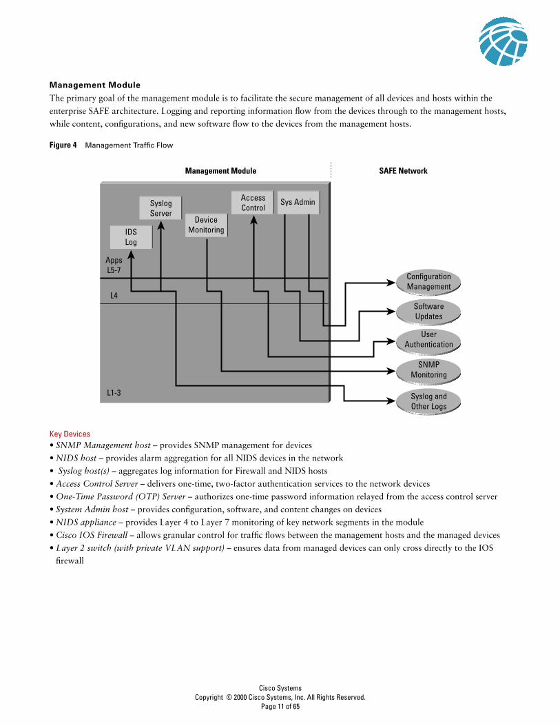
Management Module
The primary goal of the management module is to facilitate the secure management of all devices and hosts within the
enterprise SAFE architecture. Logging and reporting information flow from the devices through to the management hosts,
while content, configurations, and new software flow to the devices from the management hosts.
Figure 4 Management Traffic Flow
Key Devices• SNMP Management host – provides SNMP management for devices
• NIDS host – provides alarm aggregation for all NIDS devices in the network
• Syslog host(s) – aggregates log information for Firewall and NIDS hosts
• Access Control Server – delivers one-time, two-factor authentication services to the network devices
• One-Time Password (OTP) Server – authorizes one-time password information relayed from the access control server
• System Admin host – provides configuration, software, and content changes on devices
• NIDS appliance – provides Layer 4 to Layer 7 monitoring of key network segments in the module
• Cisco IOS Firewall – allows granular control for traffic flows between the management hosts and the managed devices
• Layer 2 switch (with private VLAN support) – ensures data from managed devices can only cross directly to the IOS
firewall
SoftwareUpdates
Management Module
SyslogServer
AccessControl
ConfigurationManagement
UserAuthentication
SNMPMonitoring
Syslog andOther Logs
DeviceMonitoringIDS
Log
AppsL5-7
L4
L1-3
SAFE Network
Sys Admin
Cisco SystemsCopyright © 2000 Cisco Systems, Inc. All Rights Reserved.
Page 11 of 65
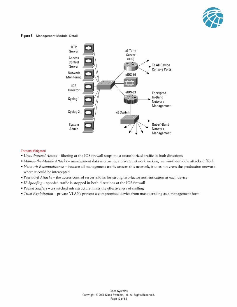
Figure 5 Management Module: Detail
Threats Mitigated• Unauthorized Access – filtering at the IOS firewall stops most unauthorized traffic in both directions
• Man-in-the-Middle Attacks – management data is crossing a private network making man-in-the-middle attacks difficult
• Network Reconnaissance – because all management traffic crosses this network, it does not cross the production network
where it could be intercepted
• Password Attacks – the access control server allows for strong two-factor authentication at each device
• IP Spoofing – spoofed traffic is stopped in both directions at the IOS firewall
• Packet Sniffers – a switched infrastructure limits the effectiveness of sniffing
• Trust Exploitation – private VLANs prevent a compromised device from masquerading as a management host
OTPServer
AccessControlServer
x6 TermServer(IOS)
To All DeviceConsole Ports
EncryptedIn-BandNetworkManagement
Out-of-BandNetworkManagement
x6 Switch
elDS-91
elOS-21
NetworkMonitoring
IDSDirector
Syslog 1
Syslog 2
SystemAdmin
Cisco SystemsCopyright © 2000 Cisco Systems, Inc. All Rights Reserved.
Page 12 of 65

Figure 6 Attack Mitigation Roles for Management Module
Design GuidelinesAs can be seen in the above diagram, the SAFE enterprise management network has two network segments that are separated
by an IOS router that acts as a firewall and a VPN termination device. The segment outside the firewall connects to all the
devices that require management. The segment inside the firewall contains the management hosts themselves and the IOS
routers that act as terminal servers. The remaining interface connects to the production network but only for IPSec-protected
management traffic from predetermined hosts. This allows for management of a Cisco device that did not physically have
enough interfaces to support the normal management connection. The IOS firewall is configured to allow syslog information
into the management segment, as well as telnet, SSH, and SNMP if these are first initiated by the inside network.
Both management subnets operate under an address space that is completely separate from the rest of the production
network. This ensures that the management network will not be advertised by any routing protocols. This also enables the
production network devices to block any traffic from the management subnets that appears on the production network links.
The management module provides configuration management for nearly all devices in the network through the use of two
primary technologies: Cisco IOS routers acting as terminal servers and a dedicated management network segment. The
routers provide a reverse-telnet function to the console ports on the Cisco devices throughout the enterprise. More extensive
management features (software changes, content updates, log and alarm aggregation, and SNMP management) are provided
through the dedicated management network segment. The few other unmanaged devices and hosts are managed through
IPSec tunnels that originate from the management router.
OTPServer
AccessControl Server
x6 TermServer(IOS)
To All DeviceConsole Ports
Encrypted In-BandNetwork Management
Hosts IDS for Local Attack
Private VLANs
Two-FactorAuthentication
AAA Services
Read-Only SNMP
Network Log Data
SSH Where Possible
Config and ContentManagement
ComprehensiveLayer 4-7 Analysis
Stateful PacketFiltering
IPsec Terminationfor Management
Out-of-BandNetwork
Management
x6 Switch
elDS-91
elOS-21
NetworkMonitoring
IDSDirector
Syslog1
Syslog2
SystemAdmin
OOB ConfigManagement
Cisco SystemsCopyright © 2000 Cisco Systems, Inc. All Rights Reserved.
Page 13 of 65
Because the management network has administrative access to nearly every area of the network, it can be a very attractive
target to hackers. The management module has been built with several technologies designed to mitigate those risks. The first
primary threat is a hacker attempting to gain access to the management network itself. This threat can only be mitigated
through the effective deployment of security features in the remaining modules in the enterprise. All the remaining threats
assume that the primary line of defense has been breached. To mitigate the threat of a compromised device, access control is
implemented at the firewall, and at every other possible device, to prevent exploitation of the management channel. A
compromised device cannot even communicate with other hosts on the same subnet because private VLANs on the
management segment switches force all traffic from the managed devices directly to the IOS firewall where filtering takes
place. Password sniffing only reveals useless information because of the one-time password environment. Host and Network
IDS are also implemented on the management subnet and are configured in a very restrictive stance. Because the types of
traffic on this network should be very limited, any signature match on this segment should be met with an immediate
response.
SNMP management has its own set of security needs. Keeping SNMP traffic on the management segment allows it to traverse
an isolated segment when pulling management information from devices. With SAFE, SNMP management pulls information
only from devices rather than allowing it to push changes. To ensure this, each device is only configured with a “read-only”
string.
Proper aggregation and analysis of the syslog information is critical to the proper management of a network. From a security
perspective, syslog provides important information regarding security violations and configuration changes. Depending on
the device in question, different levels of syslog information might be required. Having full logging with all messages sent
might provide too much information for an individual or syslog analysis algorithm to sort. Logging for the sake of logging
does not improve security.
For the SAFE validation lab, all configurations were done using standalone management applications and the command-line
interface (CLI). Nothing in SAFE, however, precludes using policy management systems for configuration. Establishing this
management module makes deployments of such technology completely viable. CLI and standalone management
applications were chosen because the majority of current network deployments use this configuration method.
AlternativesComplete out-of-band management is not always possible because some devices might not support it or there might be
geographic differences that dictate in-band management. When in-band management is required, more emphasis needs to
be placed on securing the transport of the management protocols. This can be through the use of IPSec, SSH, SSL, or any
other encrypted and authenticated transport that allows management information to traverse it. When management happens
on the same interface that a device uses for user data, importance needs to be placed on passwords, community strings,
cryptographic keys, and the access-lists that control communications to the management services.
Future Near-Term Architecture GoalsThe current reporting and alarming implementation is split across multiple hosts. Some hosts have intelligence for analyzing
firewall and IDS data, while others are better-suited to analyze router and switch data. In the future, all data will aggregate
to the same set of redundant hosts so that event correlation between all the devices can occur.
Cisco SystemsCopyright © 2000 Cisco Systems, Inc. All Rights Reserved.
Page 14 of 65

Core Module
The core module in the SAFE architecture is nearly identical to the core module of any other network architecture. It merely
routes and switches traffic as fast as possible from one network to another.
Key Devices• Layer 3 switching – route and switch production network data from one module to another
Figure 7 Core Module: Detail
Threats Mitigated• Packet Sniffers – a switched infrastructure limits the effectiveness of sniffing
Design GuidelinesStandard implementation guidelines were followed in accordance with the “core, distribution, and access layer” deployments
commonly seen in well-designed Cisco-based networks.
Though no unique requirements are defined by the SAFE architecture for the core of enterprise networks, the core switches
follow the switch security axiom in the “Switches Are Targets” section, to ensure that they are well protected against direct
attacks.
Building Distribution Module
The goal of this module is to provide distribution layer services to the building switches; these include routing, quality of
service (QoS), and access control. Requests for data flow into these switches and onto the core, and responses follow the
identical path in reverse.
Key Devices• Layer 3 switches – aggregate Layer 2 switches in building module and provide advanced services
To BuildingDistribution Module
To EdgeDistributionModule
To Server Module
eL3sw-3 eL3sw-4
Cisco SystemsCopyright © 2000 Cisco Systems, Inc. All Rights Reserved.
Page 15 of 65

Figure 8 Building Distribution Module: Detail
Threats Mitigated• Unauthorized Access – attacks against server module resources are limited by Layer 3 filtering of specific subnets
• IP Spoofing – RFC 2827 filtering stops most spoofing attempts
• Packet Sniffers – a switched infrastructure limits the effectiveness of sniffing
Figure 9 Attack Mitigation Roles for Building Distribution Module
Design GuidelinesIn addition to standard network design fundamentals, the optimizations described in the “Switches Are Targets” section were
implemented to provide added security within the enterprise user community. Intrusion detection is not implemented at the
building distribution module because it is implemented in the modules that contains the resources that are likely to be
attacked for their content (server, remote access, Internet, and so forth). The building distribution module provides the first
line of defense and prevention against internally originated attacks. It can mitigate the chance of a department accessing
confidential information on another department’s server through the use of access control. For example, a network that
contains marketing and research and development might segment off the R&D server to a specific VLAN and filter access
to it ensuring that only R&D staff have access to it. For performance reasons, it is important that this access control be
implemented on a hardware platform that can deliver filtered traffic at near wire rates. This generally dictates the use of
Layer 3 switching as opposed to more traditional dedicated routing devices. This same access control can also prevent local
source-address spoofing through the use of RFC 2827 filtering. Finally, subnet isolation is used to route voice-over-IP (VoIP)
traffic to the call manager and any associated gateways. This prevents VoIP traffic from crossing the same segments that all
other data traffic crosses, reducing the likelihood of sniffing voice communications, and allows a smoother implementation
of QoS.
To Building Access Module
To Core Module
eL3sw-5 eL3sw-6
To Building Access Module
To Core Module
Inter-Subnet Filtering
RFC2827 Filtering
Cisco SystemsCopyright © 2000 Cisco Systems, Inc. All Rights Reserved.
Page 16 of 65

AlternativesDepending on the size and performance requirements of the network, the distribution layer can be combined with the core
layer to reduce the number of devices required in the environment.
Building Module
SAFE defines the building module as the extensive network portion that contains end-user workstations, phones, and their
associated Layer 2 access points. Its primary goal is to provide services to end users.
Key Devices• Layer 2 switch – provides Layer 2 services to phones and user workstations
• User workstation – provides data services to authorized users on the network
• IP phone – provides IP telephony services to users on the network
Figure 10 Building Access Module: Detail
Threats Mitigated• Packet sniffers – a switched infrastructure and default VLAN services limit the effectiveness of sniffing
• Virus and Trojan horse applications – host-based virus scanning prevents most viruses and many Trojan horses
Figure 11 Attack Mitigation Roles for Building Access Module
eL2sw-11 eL2sw-12
To Building Distribution Module
To Building Distribution Module
VLANs
Host Virus Scanning
Cisco SystemsCopyright © 2000 Cisco Systems, Inc. All Rights Reserved.
Page 17 of 65

Design GuidelinesBecause user devices are generally the largest single element of the network, implementing security in a concise and effective
manner is challenging. From a security perspective, the building distribution module, rather than anything in the building
module, provides most of the access control that is enforced at the end-user level. This is because the Layer 2 switch that the
workstations and phones connect to has no capability for Layer 3 access control. In addition to the network security
guidelines described in the switch security axiom, host-based virus scanning is implemented at the workstation level.
Server Module
The server module’s primary goal is to provide application services to end users and devices. Traffic flows on the server
module are inspected by on-board intrusion detection within the Layer 3 switches.
Key Devices• Layer 3 Switch – provides layer three services to the servers and inspects data crossing the server module with NIDS
• Call Manager – performs call routing functions for IP telephony devices in the enterprise
• Corporate and Department Servers – delivers file, print, and DNS services to workstations in the building module
• E-Mail Server – provide SMTP and POP3 services to internal users
Figure 12 Server Module: Detail
Threats Mitigated• Unauthorized Access – mitigated through the use of host-based intrusion detection and access control
• Application Layer Attacks – operating systems, devices, and applications are kept up to date with the latest security fixes
and protected by host-based IDS
• IP Spoofing – RFC 2827 filtering prevents source address spoofing
• Packet Sniffers – a switched infrastructure limits the effectiveness of sniffing
• Trust Exploitation – trust arrangements are very explicit, private VLANs prevent hosts on the same subnet from
communicating unless necessary
• Port Redirection – host-based IDS prevents port redirection agents from being installed
CorporateServer
To Core Module
eL3sw-1 eL3sw-2
InternalEmail
Dept.Server
CiscoCallManager
Cisco SystemsCopyright © 2000 Cisco Systems, Inc. All Rights Reserved.
Page 18 of 65

Figure 13 Attack Mitigation Roles for Server Module
Design GuidelinesThe server module is often overlooked from a security perspective. When examining the levels of access most employees have
to the servers to which they attach, the servers can often become the primary goal of internally originated attacks. Simply
relying on effective passwords does not provide for a comprehensive attack mitigation strategy. Using host and
network-based IDS, private VLANs, access control, and good system administration practices (such as keeping systems up
to date with the latest patches), provides a much more comprehensive response to attacks.
Because the NIDS system is limited in the amount of traffic it can analyze, it is important to send it attack-sensitive traffic
only. This varies from network to network, but should likely include SMTP, Telnet, FTP, and WWW. The switch-based NIDS
was chosen because of its ability to look only at interesting traffic across all VLANs as defined by the security policy. Once
properly tuned, this IDS can be set up in a restrictive manner, because required traffic streams should be well known.
AlternativesLike the building distribution module, the server module can be combined with the core module if performance needs do not
dictate separation. For very sensitive high-performance server environments, the NIDS capability in the Layer 3 switch can
be scaled by installing more than one NIDS blade and directing policy-matched traffic to specific blades.
Edge Distribution Module
This module’s goal is to aggregate the connectivity from the various elements at the edge. Traffic is filtered and routed from
the edge modules and routed into the core.
Key Devices• Layer 3 switches – aggregate edge connectivity and provide advanced services
InternalEmail
Dept.Server
CiscoCallManager
To Core Module
NIDS for Server AttacksPrivate VLANs for Server ConnectionsRFC2827 Filtering
Host IDS for Local Attack
Cisco SystemsCopyright © 2000 Cisco Systems, Inc. All Rights Reserved.
Page 19 of 65

Figure 14 Edge Distribution Module: Detail
Threats Mitigated• Unauthorized Access – filtering provides granular control over specific edge subnets and their ability to reach areas within
the campus
• IP Spoofing – RFC 2827 filtering limits locally initiated spoof attacks
• Network Reconnaissance – filtering limits nonessential traffic from entering the campus limiting a hackers ability to
perform network recon
• Packet Sniffers – a switched infrastructure limits the effectiveness of sniffing
Figure 15 Attack Mitigation Roles for Edge Distribution Module
To e-CommerceModule
To CorporateInternet Module
To VPN/RemoteAccess ModuleTo
CoreModule
eL3sw-7
eL3sw-8
To WAN Module
To e-CommerceModule
To CorporateInternet Module
To VPN/RemoteAccess Module
To CoreModule
To WAN Module
Layer 3 Access Control
RFC2827 Filtering
Cisco SystemsCopyright © 2000 Cisco Systems, Inc. All Rights Reserved.
Page 20 of 65

Design GuidelinesThe edge distribution module is similar in some respects to the building distribution module in terms of overall function.
Both modules employ access control to filter traffic, although the edge distribution module can rely somewhat on the entire
edge functional area to perform additional security functions. Both modules use Layer 3 switching to achieve high
performance, but the edge distribution module can add additional security functions because the performance requirements
are not as great. The edge distribution module provides the last line of defense for all traffic destined to the campus module
from the edge module. This includes mitigation of spoofed packets, erroneous routing updates, and provisions for network
layer access control.
AlternativesLike the server and building distribution modules, the edge distribution module can be combined with the core module if
performance requirements are not as stringent as the SAFE reference implementation. NIDS is not present in this module,
but could be placed here through the use of IDS line cards in the Layer 3 switches. It would then reduce the need for NIDS
appliances at the exit from the critical edge modules as they connect to the campus. However, performance reasons may
dictate, as they did in SAFE’s reference design, that dedicated intrusion detection be placed in the various edge modules as
opposed to the edge distribution module.
Cisco SystemsCopyright © 2000 Cisco Systems, Inc. All Rights Reserved.
Page 21 of 65

Enterprise Edge
The following is a detailed analysis of all the modules contained within the Enterprise Edge.
Figure 16 Enterprise Edge Detail – Part 1
CorporateInternet Module
To EdgeDistribution
Module
To VPN/RemoteAccess Module
ISP A
ISP A Module
ISP B
ISP B Module
To EdgeDistribution
Module
E-commerceModule
Cisco SystemsCopyright © 2000 Cisco Systems, Inc. All Rights Reserved.
Page 22 of 65
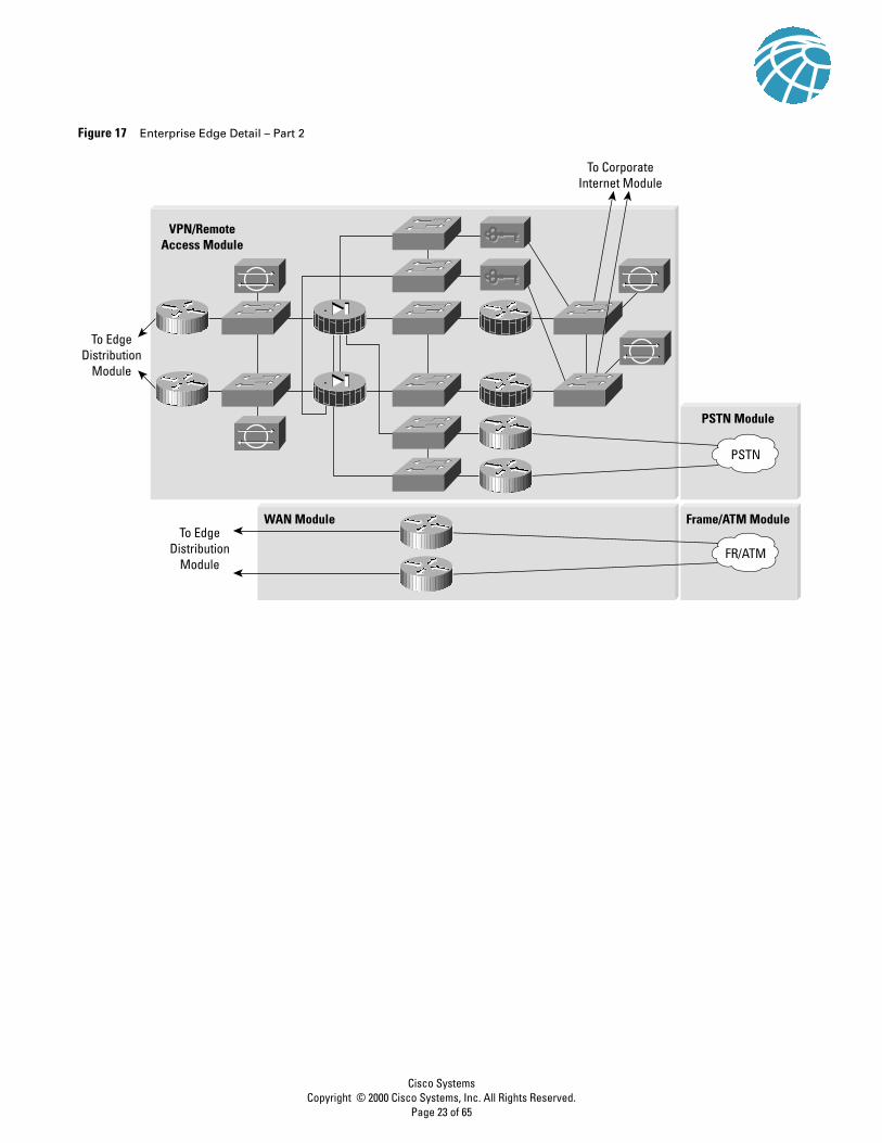
Figure 17 Enterprise Edge Detail – Part 2
PSTN Module
Frame/ATM ModuleWAN ModuleTo Edge
DistributionModule
To EdgeDistribution
Module
FR/ATM
PSTN
VPN/RemoteAccess Module
To CorporateInternet Module
Cisco SystemsCopyright © 2000 Cisco Systems, Inc. All Rights Reserved.
Page 23 of 65

Corporate Internet Module
The Corporate Internet module provides internal users with connectivity to Internet services and Internet users access to
information on public servers. Traffic also flows from this module to the VPN and remote access module where VPN
termination takes place. This module is not designed to serve e-commerce type applications. Refer to the “E-Commerce
Module” section later in this document for more details on providing Internet commerce.
Figure 18 Corporate Internet Traffic Flow
Key Devices• SMTP server – acts as a relay between the Internet and the Internet mail servers – inspects content
• DNS server – serves as authoritative external DNS server for the enterprise, relays internal requests to the Internet
• FTP/HTTP server – provides public information about the organization
• Firewall – provides network-level protection of resources and stateful filtering of traffic
• NIDS appliance – provides Layer 4 to Layer 7 monitoring of key network segments in the module
• URL Filtering Server – filters unauthorized URL requests from the enterprise
Corporate Internet ModuleEdge DistributionModule
SMTP Inspection
URL Filtering
FTP
Web
Incoming FTP,WEB, DNS, SMTP
OutgoingSMTP, DNS
In/OutSMTP, DNS
OutgoingInternet
OutgoingInternet
In/OutVPN
Out/InVPN
SMTPDNS
Apps
L5-7
L1-3
L4
ISP Module
Cisco SystemsCopyright © 2000 Cisco Systems, Inc. All Rights Reserved.
Page 24 of 65

Figure 19 Corporate Internet Module: Detail
Threats Mitigated• Unauthorized Access – mitigated through filtering at the ISP, edge router, and corporate firewall
• Application Layer Attacks – mitigated through IDS at the host and network levels
• Virus and Trojan Horse – mitigated through e-mail content filtering and host IDS
• Password Attacks – limited services available to brute force, OS and IDS can detect the threat
• Denial of Service – CAR at ISP edge and TCP setup controls at firewall
• IP Spoofing – RFC 2827 and 1918 filtering at ISP edge and enterprise edge router
• Packet Sniffers – switched infrastructure and host IDS limits exposure
• Network Reconnaissance – IDS detects recon, protocols filtered to limit effectiveness
• Trust Exploitation – restrictive trust model and private VLANs limit trust-based attacks
• Port Redirection – restrictive filtering and host IDS limit attack
ISP B
WEB/FTP SMTPDNS
elDS-81
ePIX-33
ePIX-31
elDS-84
elDS-85
elOS-22
To EdgeDistribution
URL Filtering
elOS-21
To VPN/RemoteAccess
elOS-24
elOS-23
ISP A
elDS-82
elDS-86 elDS-83
Cisco SystemsCopyright © 2000 Cisco Systems, Inc. All Rights Reserved.
Page 25 of 65

Figure 20 Attack Mitigation Roles for Corporate Internet Module
Design GuidelinesThe heart of the module is a pair of resilient firewalls, which provide protection for the Internet public services and internal
users. Stateful inspection examines traffic in all directions ensuring only legitimate traffic crosses the firewall. Aside from the
Layer 2 and Layer 3 resilience built into the module and the stateful failover capability of the firewall, all other design
considerations center around security and attack mitigation.
Starting at the customer-edge router in the ISP, the egress out of the ISP rate-limits nonessential traffic that exceeds
prespecified thresholds in order to mitigate against (D)DoS attacks. Also at the egress of the ISP router, RFC 1918 and RFC
2827 filtering mitigate against source-address spoofing of local networks and private address ranges.
At the ingress of the first router on the Enterprise network, basic filtering limits the traffic to the expected (addresses and IP
services) traffic, providing a coarse filter for the most basic attacks. RFC 1918 and 2827 filtering is also provided here as a
verification of the ISP’s filtering. In addition, because of the enormous security threat that they create, the router is configured
to drop most fragmented packets that should not generally be seen for standard traffic types on the Internet. Any legitimate
traffic lost because of this filtering is considered acceptable when compared to the risk of allowing such traffic. Finally, any
IPSec traffic destined for the VPN and remote access module is routed appropriately. Filtering on the interface connected to
the VPN module is configured to allow only IPSec traffic to cross, and only when originated from and sent to authorized
peers. With remote access VPNs you generally do not know the IP address of the system coming in so filtering can be specific
only to the head-end peers with which the remote users are communicating.
The NIDS appliance at the public side of the firewall is monitoring for attacks based on Layer 4 to Layer 7 analysis and
comparisons against known signatures. Because the ISP and enterprise edge router are filtering certain address ranges and
ports, this allows the NIDS appliance to focus on some of the more complex attacks. Still, this NIDS should have alarms set
to a lower level than appliances on the inside of the firewall because alarms seen here do not represent actual breaches, but
merely attempts.
To EdgeDistribution
To VPN/RemoteAccess
ISP A
SMTP ContentInspection
Inspect Outbound Trafficfor Unauthorized URLs
Spoof Mitigation
Basic Filtering
Spoof Mitigation
(D)DoS Rate-Limiting
Stateful Packet Filtering
Basic Layer 7 Filtering
Host DoS Mitigation
Host IDS for Local Attack Mitigation
Focused Layer 4-7 Analysis
Focused Layer 4-7 Analysis
Broad Layer 4-7 Analysis
Cisco SystemsCopyright © 2000 Cisco Systems, Inc. All Rights Reserved.
Page 26 of 65
The firewall provides connection state enforcement and detailed filtering for sessions initiated through the firewall. Publicly
addressable servers have some protection against TCP SYN floods through the use of half-open connection limits on the
firewall. From a filtering standpoint, in addition to limiting traffic on the public services segment to relevant addresses and
ports, filtering in the opposite direction also takes place. If an attack compromises one of the public servers (by circumventing
the firewall, host-based IDS, and network-based IDS) that server should not be able to further attack the network. To mitigate
against this type of attack, specific filtering prevents any unauthorized requests from being generated by the public servers
to any other location. As an example, the Web server should be filtered so that it cannot originate requests of its own, but
merely respond to requests from clients. This helps prevent a hacker from downloading additional utilities to the
compromised box after the initial attack. It also helps stop unwanted sessions from being triggered by the hacker during the
primary attack. An attack that generates an xterm from the Web server through the firewall to the hacker’s machine is an
example of such an attack. In addition, private VLANs prevent a compromised public server from attacking other servers on
the same segment. This traffic is not even detected by the firewall, which is why private VLANs are critical.
Traffic on the content inspection segment is limited to URL filtering requests from the firewall to the URL filtering device.
In addition, authenticated requests are allowed from the enterprise URL filtering device out to a master server for database
updates. The URL filtering device inspects outbound traffic for unauthorized WWW requests. It communicates directly with
the firewall and approves or rejects URL requests sent to its URL inspection engine by the firewall. Its decision is based on
a policy managed by the enterprise using classification information of the WWW provided by a third-party service. URL
inspection was preferred over standard access filtering because IP addresses often change for unauthorized Web sites, and
such filters can grow to be very large. Host-based IDS software on this server protects against possible attacks that somehow
circumvent the firewall.
The public services segment includes an NIDS appliance in order to detect attacks on ports that the firewall is configured to
permit. These most often are application layer attacks against a specific service or a password attack against a protected
service. You need to set this NIDS in a more restrictive stance than the NIDS on the outside of the firewall because signatures
matched here have successfully passed through the firewall. Each of the servers have host intrusion detection software on
them to monitor against any rogue activity at the OS level, as well as activity in common server applications (HTTP, FTP,
SMTP, and so forth). The DNS host should be locked down to respond only to desired commands and eliminate any
unnecessary responses that might assist hackers in network reconnaissance. This includes preventing zone-transfers from
anywhere but the internal DNS servers. The SMTP server includes mail content inspection services that mitigate against virus
and Trojan-type attacks generated against the internal network that are usually introduced through the mail system. The
firewall itself filters SMTP messages at Layer 7 to allow only necessary commands to the mail server.
The NIDS appliance on the inside interface of the firewall provides a final analysis of attacks. Very few attacks should be
detected on this segment because only responses to initiated requests, and a few select ports from the public services segment,
are allowed to the inside. Only sophisticated attacks should be seen on this segment because they generally mean a system
on the public services segment has been compromised and the hacker is attempting to leverage this foot-hold to attack the
internal network. For example, if the public SMTP server were compromised, a hacker might try to attack the internal mail
server over TCP port 25, which is permitted to allow mail transfer between the two hosts. If attacks are seen on this segment,
the responses to those attacks should be more severe than those on other segments because they probably indicate that a
compromise has already occurred. The use of TCP resets to thwart, for example, the SMTP attack mentioned above, should
be seriously considered.
Cisco SystemsCopyright © 2000 Cisco Systems, Inc. All Rights Reserved.
Page 27 of 65

AlternativesThere are several alternative designs for this module. For example, depending on your attitude towards attack awareness,
the NIDS appliances might not be required in front of the firewall. In fact, without basic filtering on the access router, this
type of monitoring is not recommended. With the appropriate basic filters, which exist in this design, the IDS outside the
firewall can provide important alarm information that would otherwise be dropped by the firewall. Because the amount of
alarms generated on this segment is probably large, alarms generated here should have a lower severity than alarms generated
behind a firewall. Also, consider logging alarms from this segment to a separate management station to ensure that legitimate
alarms from other segments get the appropriate attention. With the visibility that NIDS outside the firewall provides,
evaluation of the attack types your organization is attracting can be better seen. In addition, evaluation of the effectiveness
of ISP and enterprise edge filters can be performed.
Another possible alternative to the proposed design is the elimination of the router between the firewall and the edge
distribution module. Though its functions can be integrated into the edge distribution module, the functional separation
between modules would be lost because the edge distribution switches would need to be aware of the entire topology of the
corporate Internet module to ensure proper routing. In addition, this limits your ability to deploy this architecture in a
modular fashion. If an enterprise’s current core is Layer 2, for example, the routing provided in the corporate Internet module
would be required.
Near-Term Architecture GoalsDeveloping Cisco firewall technology that can communicate directly with other content inspection devices is needed (for
example, network-based virus scanning). Currently, URL filtering is the only supported content filtering function that is
directly integrated with Cisco firewall technology. Nonintegrated products rely on users operating in a proxy mode that does
not properly scale.
VPN and Remote Access Module
As the name implies, the primary objective of this module is three-fold: terminate the VPN traffic from remote users, provide
a hub for terminating VPN traffic from remote sites, and terminate traditional dial-in users. All the traffic forwarded to the
edge distribution is from remote corporate users that are authenticated in some fashion before being allowed through the
firewall.
Figure 21 Remote Access VPN Module Traffic Flow
Remote Access VPN ModuleEdge DistributionModule
User Authentication
Clear TextRemote Traffic
DialRemote Access
EncryptedRemote Access
EncryptedSite-to-Site
L4-7
L1-3
ISP Module
IPsec Termination
Cisco SystemsCopyright © 2000 Cisco Systems, Inc. All Rights Reserved.
Page 28 of 65
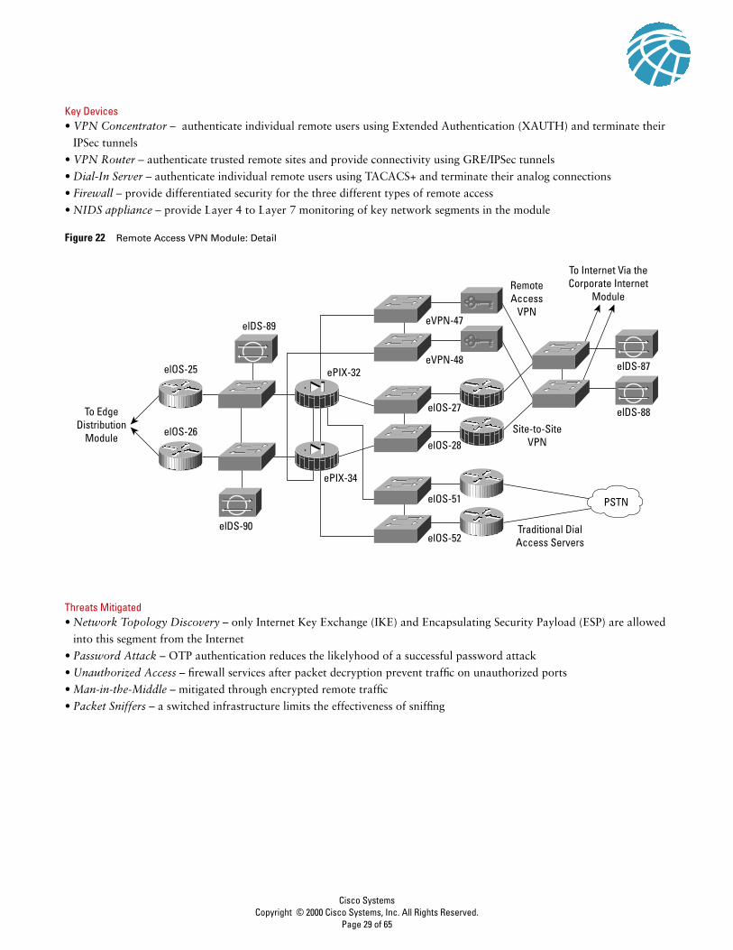
Key Devices• VPN Concentrator – authenticate individual remote users using Extended Authentication (XAUTH) and terminate their
IPSec tunnels
• VPN Router – authenticate trusted remote sites and provide connectivity using GRE/IPSec tunnels
• Dial-In Server – authenticate individual remote users using TACACS+ and terminate their analog connections
• Firewall – provide differentiated security for the three different types of remote access
• NIDS appliance – provide Layer 4 to Layer 7 monitoring of key network segments in the module
Figure 22 Remote Access VPN Module: Detail
Threats Mitigated• Network Topology Discovery – only Internet Key Exchange (IKE) and Encapsulating Security Payload (ESP) are allowed
into this segment from the Internet
• Password Attack – OTP authentication reduces the likelyhood of a successful password attack
• Unauthorized Access – firewall services after packet decryption prevent traffic on unauthorized ports
• Man-in-the-Middle – mitigated through encrypted remote traffic
• Packet Sniffers – a switched infrastructure limits the effectiveness of sniffing
elOS-25
elOS-27
elOS-51
elOS-52
elOS-28
elDS-88
elDS-87
elOS-26
elDS-89
elDS-90
To EdgeDistribution
Module
ePIX-34
eVPN-47
RemoteAccess
VPN
To Internet Via theCorporate Internet
Module
Traditional DialAccess Servers
Site-to-SiteVPN
eVPN-48ePIX-32
PSTN
Cisco SystemsCopyright © 2000 Cisco Systems, Inc. All Rights Reserved.
Page 29 of 65
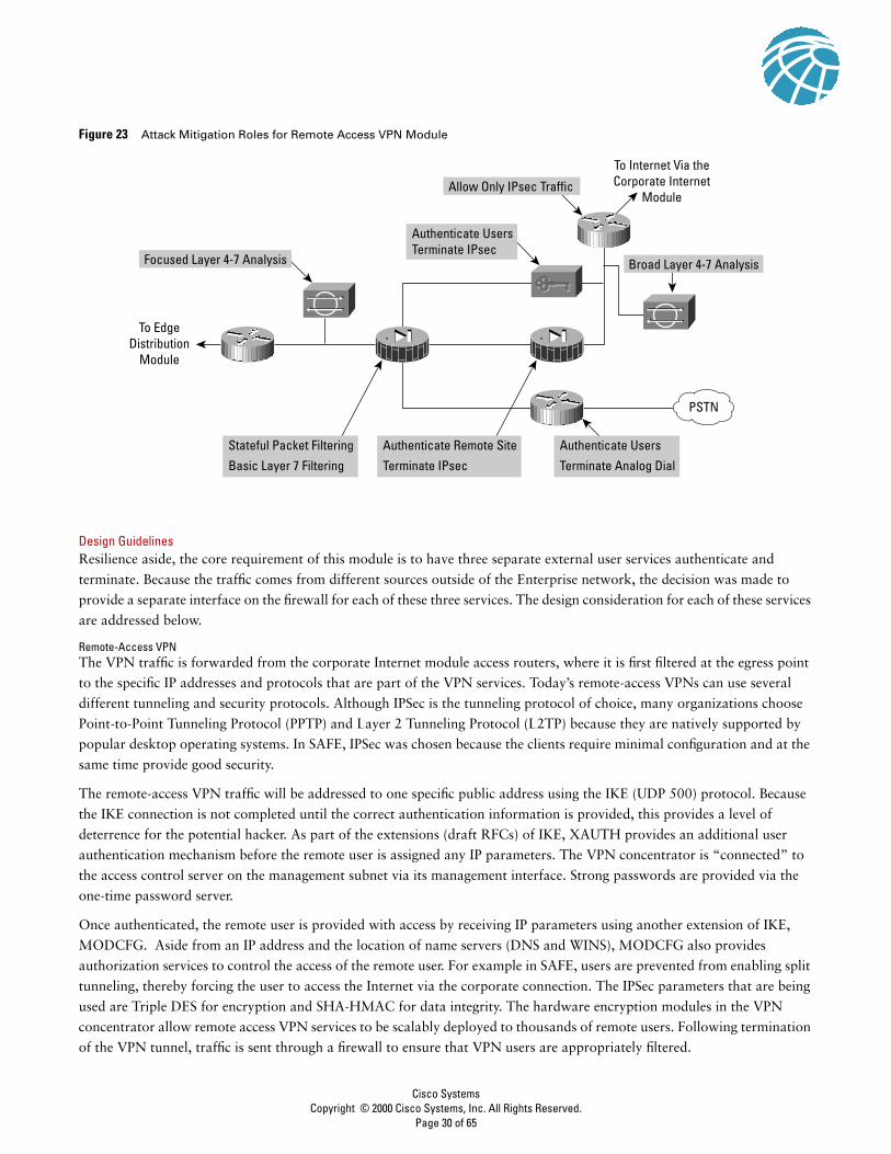
Figure 23 Attack Mitigation Roles for Remote Access VPN Module
Design GuidelinesResilience aside, the core requirement of this module is to have three separate external user services authenticate and
terminate. Because the traffic comes from different sources outside of the Enterprise network, the decision was made to
provide a separate interface on the firewall for each of these three services. The design consideration for each of these services
are addressed below.
Remote-Access VPNThe VPN traffic is forwarded from the corporate Internet module access routers, where it is first filtered at the egress point
to the specific IP addresses and protocols that are part of the VPN services. Today’s remote-access VPNs can use several
different tunneling and security protocols. Although IPSec is the tunneling protocol of choice, many organizations choose
Point-to-Point Tunneling Protocol (PPTP) and Layer 2 Tunneling Protocol (L2TP) because they are natively supported by
popular desktop operating systems. In SAFE, IPSec was chosen because the clients require minimal configuration and at the
same time provide good security.
The remote-access VPN traffic will be addressed to one specific public address using the IKE (UDP 500) protocol. Because
the IKE connection is not completed until the correct authentication information is provided, this provides a level of
deterrence for the potential hacker. As part of the extensions (draft RFCs) of IKE, XAUTH provides an additional user
authentication mechanism before the remote user is assigned any IP parameters. The VPN concentrator is “connected” to
the access control server on the management subnet via its management interface. Strong passwords are provided via the
one-time password server.
Once authenticated, the remote user is provided with access by receiving IP parameters using another extension of IKE,
MODCFG. Aside from an IP address and the location of name servers (DNS and WINS), MODCFG also provides
authorization services to control the access of the remote user. For example in SAFE, users are prevented from enabling split
tunneling, thereby forcing the user to access the Internet via the corporate connection. The IPSec parameters that are being
used are Triple DES for encryption and SHA-HMAC for data integrity. The hardware encryption modules in the VPN
concentrator allow remote access VPN services to be scalably deployed to thousands of remote users. Following termination
of the VPN tunnel, traffic is sent through a firewall to ensure that VPN users are appropriately filtered.
To EdgeDistribution
Module
To Internet Via theCorporate Internet
Module
Stateful Packet Filtering
Basic Layer 7 Filtering
Authenticate Remote Site
Terminate IPsec
Authenticate Users
Terminate Analog Dial
Authenticate UsersTerminate IPsec
Focused Layer 4-7 Analysis
Allow Only IPsec Traffic
Broad Layer 4-7 Analysis
PSTN
Cisco SystemsCopyright © 2000 Cisco Systems, Inc. All Rights Reserved.
Page 30 of 65

Secure management of this service is achieved by pushing all IPSec and security parameters to the remote users from the
central site. Additionally, connections to all management functions are on a dedicated management interface.
Dial-in access usersThe traditional dial-in users are terminated on one of the two access routers with built-in modems. Once the Layer 1
connection is established between the user and the server, three-way CHAP is used to authenticate the user. As in the
remote-access VPN service the AAA and one-time password servers are used to authenticate and provide passwords. Once
authenticated the users are provided with IP addresses from an IP pool through PPP.
Site-to-site VPNThe VPN traffic associated with site-to-site connections consists of GRE tunnels protected by an IPSec protocol in transport
mode using Encapsulated Security Payload (ESP). As in the remote-access case, the traffic that is forwarded from the
corporate Internet module can be limited to the specific destination addresses on the two VPN routers and the source
addresses expected from the remote sites. The ESP protocol (IP 50) and the IKE protocol will be the only two expected on
this link.
GRE is used to provide a full-service routed link which will carry multiprotocol, routing protocol, and multicast traffic.
Because routing protocols (Enhanced Interior Gateway Routing Protocol [EIGRP] is being used between remote sites) can
detect link failure, the GRE tunnel provides a resilience mechanism for the remote sites if they build two generic routing
encapsulation (GRE) connections one to each of the central VPN routers.
As in remote-access VPN, 3DES and SHA-HMAC are used for IKE and IPSec parameters to provide the maximum security
with little effect on performance. IPSec hardware accelerators are used in the VPN routers.
Rest of the moduleThe traffic from the three services is aggregated by the firewall onto one private interface before being sent to the edge
distribution module via a pair of routers. The firewall must be configured with the right type of constraining access control
to allow only the appropriate traffic through to the inside interface of the firewall from each of the services. A pair of NIDS
appliances are positioned at the public side of the module to detect any network “reconnaissance” activity targeted at the
VPN termination devices. On this segment, only IPSec (IKE/ESP) traffic should be seen. Because the NIDS system can not see
inside the IPSec packets, any alarm on this network indicates a failure or compromise of the surrounding devices. As such,
these alarms should be set to high severity levels. A second pair of NIDS are positioned after the firewall to detect any attacks
that made it through the rest of the module. This NIDS device also has a restrictive policy in place. All users crossing this
segment should be bound to, or coming from an remote location so any shunning or TCP resets will only affect those users.
AlternativesIn VPN and authentication technology, there are many alternatives available depending on the requirements of the network.
These alternatives are listed below for reference, but the details are not addressed in this document.
• Smart-card and/or Bio-metric authentication
• L2TP and/or PPTP remote-access VPN tunnels
• Certificate Authorities (CAs)
• IKE keep-alive resilience mechanism
• Multiprotocol Label Switching (MPLS) VPNs
Cisco SystemsCopyright © 2000 Cisco Systems, Inc. All Rights Reserved.
Page 31 of 65

WAN Module
Rather than being all-inclusive of potential WAN designs, this module shows resilience and security for WAN termination.
Using Frame Relay encapsulation, traffic is routed between remote sites and the central site.
Key Devices• IOS Router – using routing, access-control, QoS mechanisms
Figure 24 WAN Module: Detail
Threats Mitigated• IP Spoofing – mitigated through L3 filtering
• Unauthorized Access – simple access control on the router can limit the types of protocols to which branches have access
Figure 25 Attack Mitigation Roles for WAN Module
Design GuidelinesThe resilience is provided by the dual connection from the service provider, through the routers, and to the edge distribution
module. Security is provided by using IOS security features. Input access-lists are used to block all unwanted traffic from the
remote branch.
AlternativesSome organizations that are very concerned about information privacy encrypt highly confidential traffic on their WAN
links. Similarly to site-to-site VPNs, you can use IPSec to achieve this information privacy.
To EdgeDistribution
Module
elOS-61
elOS-62
FR/ATM
To EdgeDistribution
ModuleFR/ATM
Layer 3 Access Control
Cisco SystemsCopyright © 2000 Cisco Systems, Inc. All Rights Reserved.
Page 32 of 65

E-Commerce Module
Because e-commerce is the primary objective of this module, the balance between access and security must be carefully
weighed. Splitting the e-commerce transaction into three components allows the architecture to provide various levels of
security without impeding access.
Figure 26 E-Commerce Traffic Flow
Key Devices• Web server – acts as the primary user interface for the navigation of the e-commerce store
• Application server – is the platform for the various applications required by the Web server
• Database server – is the critical information that is the heart of the e-commerce business implementation
• Firewall – governs communication between the various levels of security and trust in the system
• NIDS appliance – provides monitoring of key network segments in the module
• Layer 3 switch with IDS module – is the scalable e-commerce input device with integrated security monitoring
Figure 27 E-Commerce Module: Detail
e-Commerce ModuleEdge DistributionModule
WebAppsDB
IncomingRequests
Apps
L1-3
L4
L5-7
ISP Module
To EdgeDistribution
Module
DatabaseServers
ApplicationServers
WebServers
Cisco SystemsCopyright © 2000 Cisco Systems, Inc. All Rights Reserved.
Page 33 of 65

Threats Mitigated• Unauthorized Access – stateful firewalling and ACLs limit exposure to specific protocols
• Application Layer Attacks – attacks are mitigated through the use of IDS
• Denial of Service – ISP filtering and rate-limiting reduce (D)DoS potential
• IP Spoofing – RFC 2827 and 1918 prevent locally originated spoofed packets and limit remote spoof attempts
• Packet Sniffers – a switched infrastructure and HIDS limits the effectiveness of sniffing
• Network Reconnaissance – ports are limited to only what is necessary, ICMP is restricted
• Trust Exploitation – firewalls ensure communication flows only in the proper direction on the proper service
• Port Redirection – HIDS and firewall filtering limit exposure to these attacks
Figure 28 Attack Mitigation Roles for E-Commerce Module
Design Implementation DescriptionThe heart of the module is two pairs of resilient firewalls that provide protection for the three levels of servers: Web,
application, and database. Some added protection is provided by the ISP edge routers at the ISP and the Enterprise. The
design is best understood by considering the traffic flow sequence and direction for a typical e-commerce transaction.
The e-commerce customer initiates an HTTP connection to the Web server after receiving the IP address from a DNS server
hosted at the ISP network. The DNS is hosted on a different network to reduce the amount of protocols required by the
e-commerce application. The first set of firewalls must be configured to allow this protocol through to that particular
address. The return traffic for this connection is allowed back, but there is no need for any communication initiated by the
Web server back out the Internet. The firewall should block this path in order to limit the options of hackers if they had
control of one of the Web servers.
As the user navigates the Web site, certain link selections cause the Web server to initiate a request to the application server
on the inside interface. This connection must be permitted by the first firewall, as well as the associated return traffic. As in
the case with the Web server, there is no reason for the application server to initiate a connection to the Web server or even
out to the Internet. Likewise, the user’s entire session runs over HTTP and SSL with no ability to communicate directly with
the application server or the database server.
To EdgeDistribution
ISP A
Stateful Packet Filtering
Basic 7 Layer Filtering
Stateful Packet Filtering
Basic 7 Layer Filtering
Host DoS Mitigation
Spoof Mitigation
(D)DoS Rate-Limiting
Layer 4 Filtering
Broad Layer 4-7 Analysis
Wire Speed Access Control
Host IDS for Local Attack MitigationFocused Layer 4-7 Analysis
Focused Layer 4-7 Analysis
Focused Layer 4-7 Analysis
Cisco SystemsCopyright © 2000 Cisco Systems, Inc. All Rights Reserved.
Page 34 of 65

At one point, the user will want to perform a transaction. The Web server will want to protect this transaction and the SSL
protocol will be required from the Internet to the Web server. At the same time, the application server might want to query
or pass information on to the database server. These are typically SQL queries that are initiated by the application server to
the database server and not vice versa. These queries run through the second firewall to the database server. Depending on
the specific applications in use, the database server might need to communicate with back-end systems located in the server
module of the enterprise.
In summary, the firewalls must allow only three specific communication paths, each with its own protocol, and block all
other communication unless it is the return path packets that are associated with the three original paths.
The servers themselves must be fully protected especially the Web server which is a publicly-addressable host. The
operating system and Web server application must be patched to the latest versions and monitored by the host intrusion
detection software. This should mitigate against most application layer primary and secondary attacks such as port
redirection and root kits. The other servers should have similar security in case the first server or firewall is compromised.
Beyond the Firewall
The e-commerce firewalls are initially protected by the customer edge router at the ISP. At the router egress point, towards
the enterprise, the ISP can limit the traffic to the small number of protocols required for e-commerce with a destination
address of the Web servers only. Routing protocol updates (generally Border Gateway Protocol [BGP]) are required by the
edge routers, and all other traffic should be blocked. The ISP should implement rate limiting as specified in the “SAFE
Axioms” section in order to mitigate (D)DoS attacks. In addition, filtering according to RFC1918 and RFC2827 should also
be implemented by the ISP.
On the enterprise premises, the initial router serves only as an interface to the ISP. The Layer 3 switch does all the network
processing because it has features off-loaded to hardware processors. The Layer 3 switches participate in the full BGP routing
decision in order to decide which ISP has the better route to the particular user. The Layer 3 switches also provide verification
filtering in keeping with the ISP filtering described above; this provides overlapping security. Thirdly, the Layer 3 switches
provide built-in IDS monitoring. If the connection to the Internet exceeds the capacity of the IDS line card, you might need
to look only at inbound Web requests from the Internet on the IDS line card. While this will miss some http alarm signatures
(approximately 10 percent), it is better than looking at the entire stream in both directions, where many misses would occur.
The other NIDS appliances behind the various interfaces of the firewall monitor the segments for any attacks that might have
penetrated the first line of defense. For example, if the Web server is out of date, hackers could compromise it over an
application layer attack assuming they were able to circumvent the HIDS. As in the corporate Internet module, the
false-positives must be removed so that all true attack detections are treated with the correct level of priority. In fact, because
only certain types of traffic exist on certain segments, you can tune NIDS very tightly.
From an application standpoint, the communications paths between the various layers (web, apps, dbase) should be
encrypted, transactional, and highly authenticated. For example, if the apps server were to get data from the database over
some type of scripted interactive session (SSH, FTP, Telnet, and so forth) a hacker could leverage that interactive session to
initiate an application layer attack. By employing secure communications, you can limit potential threats.
The Layer 2 switches that supporting the various firewall segments provide the ability to implement private VLANs, thereby
implementing a trust model that matches the desired traffic communication on a particular segment and eliminates all others.
For example, there is usually no reason for one Web server to communicate with another Web server.
The management of the entire module is done completely out of band as in the rest of the architecture.
Cisco SystemsCopyright © 2000 Cisco Systems, Inc. All Rights Reserved.
Page 35 of 65
AlternativesThe principle alternative to this deployment is co-locating the entire system at an ISP. Though the design remains the same,
there are two primary differences. The first is that bandwidth is generally larger to the ISP and uses a LAN connection.
Though not recommended, this potentially eliminates the need for the edge routers in the proposed design. The additional
bandwidth also creates different requirements for (D)DoS mitigation. The second is the connection back to the enterprise,
which needs to be managed in a different way. Alternatives include encryption and private lines. Using these technologies
creates additional security considerations depending on the location of the connections and their intended use.
There are several variations on the primary design for this module. Aside from listing the alternatives, further discussion is
beyond the scope of this paper.
• The use of additional firewalls is one alternative. Sample communications would be edge routing -> firewall -> web server
-> firewall -> applications server -> firewall -> database server. This allows each firewall to only control communications
for one primary system.
• Load-balancing and caching technologies are not specifically discussed in this paper, but can be overlaid onto this
architecture without major modifications. A future paper will address these needs.
• For very high security requirements, the use of multiple firewall types may be considered. Note that this creates additional
management overhead in duplicating policy on disparate systems. The goal of these designs is to avoid a vulnerability in
one firewall from circumventing the security of the entire system. These types of designs tend to be very firewall centric and
do not adequately take advantage of IDS and other security technologies to mitigate the risk of a single firewall
vulnerability.
Enterprise Options
The design process is often a series of trade-offs. This short subsection of the document highlights some of the high-level
options that a network designer could implement if faced with tighter budget constraints. Some of these trade-offs are done
at the module level, while others are done at the component level.
A first option is to collapse the distribution modules into the core module. This reduces the number of Layer 3 switches by
50 percent. The cost savings would be traded-off against performance requirements in the core of the network and flexibility
to implement all the distribution security filtering.
A second option is to merge the functionality of the VPN and Remote Access module with the corporate Internet module.
Their structure is very similar, with a pair of firewalls at the heart of the module, surrounded by NIDS appliances. This may
be possible without loss of functionality if the performance of the components matches the combined traffic requirements of
the modules and if the firewall has enough interfaces to accommodate the different services. Keep in mind that as functions
are aggregated to single devices the potential for human error increases. Some organizations go even further and include the
e-commerce functions in the corporate Internet/VPN module. The authors feel that the risk of doing this far outweighs any
cost savings unless the e-commerce needs are minimal. Separation of the e-commerce traffic from general Internet traffic
allows the e-commerce bandwidth to be better optimized by allowing the ISP to place more restrictive filtering and
rate-limiting technology to mitigate against DDoS attacks.
A third option is to eliminate some of the NIDS appliances. Depending on your operational threat response strategy, you
might need fewer NIDS appliances. This number is also affected by the amount of Host IDS deployed because this might
reduce the need for NIDS in certain locations. This is discussed, where appropriate, in the specific modules.
Clearly, network design is not an exact science. Choices must always be made depending on the specific requirements facing
the designer. The authors are not proposing that any designer would implement this architecture verbatim, but would
encourage designers to make educated choices about network security grounded in this proven implementation.
Cisco SystemsCopyright © 2000 Cisco Systems, Inc. All Rights Reserved.
Page 36 of 65

Migration Strategies
SAFE is a guide for implementing security on the enterprise network. It is not meant to serve as a security policy for any
enterprise networks, nor is it meant to serve as the all-encompassing design for providing full security for all existing
networks. Rather, SAFE is a template that enables network designers to consider how they design and implement their
enterprise network in order to meet their security requirements.
Establishing a security policy should be the first activity in migrating the network to a secure infrastructure. Basic
recommendations for a security policy can be found at the end of the document in Appendix B, “Network Security Primer.”
After the policy is established, the network designer should consider the security axioms described in the first section of this
document and see how they provide more detail to map the policy on the existing network infrastructure.
There is enough flexibility in the architecture and detail about the design considerations to enable the SAFE architecture
elements to be adapted to most enterprise networks. For example, in the VPN and Remote Access module, the various flows
of traffic from public networks are each given a separate pair of terminating devices and a separate interface on the firewall.
The VPN traffic could be combined in one pair of devices, if the load requirements permitted it and the security policy was
the same for both types of traffic. On another network, the traditional dial-in and remote-access VPN users might be allowed
directly into the network because the security policy puts enough trust in the authentication mechanisms that permit the
connection to the network in the first place.
SAFE allows the designer to address the security requirements of each network function almost independently of each other.
Each module is generally self-contained and assumes that any interconnected module is only at a basic security level. This
allows network designers to use a phased approach to securing the enterprise network. They can address securing the most
critical network functions as determined by the policy without redesigning the entire network. The exception to this is the
management module. During the initial SAFE implementation, the management module should be implemented in parallel
with the first module. As the rest of the network is migrated, the management module can be connected to the remaining
locations.
This first version of the SAFE architecture is meant to address the security implementation of a generic enterprise network.
The authors know that there are many areas that need further detailed research, exploration, and improvement. Some of
these areas include, but are not limited to, the following:
• In-depth security management analysis and implementation
• Specialized design information for smaller networks
• In-depth identity, directory services, AAA technologies, and certificate authority analysis and implementation
• Scaled versions of VPN head-end and WAN design
Appendix A: Validation Lab
A reference SAFE implementation exists to validate the functionality described in this document. This appendix details the
configurations of the specific devices within each module as well as the overall guidelines for general device configuration.
The following are configuration snap-shots from the live devices in the lab. The authors do not recommend applying these
configurations directly to a production network.
Overall Guidelines
The configurations presented here correspond in part to the SAFE Axioms presented earlier in this document.
Cisco SystemsCopyright © 2000 Cisco Systems, Inc. All Rights Reserved.
Page 37 of 65

RoutersHere are the basic configuration options present on nearly all routers in the SAFE lab: ! turn off unnecessary services!no ip domain-lookupno cdp runno ip http serverno ip source-routeno service fingerno ip bootp serverno service udp-small-sno service tcp-small-s!!turn on logging and snmp!service timestamp log datetime localtimelogging 192.168.253.56logging 192.168.253.51snmp-server community Txo~QbW3XM ro 98!!set passwords and access restrictions!service password-encryptionenable secret %Z<)|z9~zqno enable passwordno access-list 99access-list 99 permit 192.168.253.0 0.0.0.255access-list 99 deny any logno access-list 98access-list 98 permit host 192.168.253.51access-list 98 deny any logline vty 0 4access-class 99 inloginpassword 0 X)[^j+#T98exec-timeout 2 0line con 0loginpassword 0 X)[^j+#T98exec-timeout 2 0line aux 0transport input nonepassword 0 X)[^j+#T98no execexitbanner motd #
This is a private system operated for and by Cisco VSEC BU.
Authorization from Cisco VSEC management is required to use this system.
Use by unauthorized persons is prohibited.
#!!Turn on NTP!clock timezone PST -8clock summer-time PST recurring
Cisco SystemsCopyright © 2000 Cisco Systems, Inc. All Rights Reserved.
Page 38 of 65

ntp authenticatentp authentication-key 1 md5 -UN&/6[oh6ntp trusted-key 1ntp access-group peer 96ntp server 192.168.254.57 key 1access-l 96 permit host 192.168.254.57access-l 96 deny any log!!Turn on AAA!aaa new-modelaaa authentication login default tacacs+aaa authentication login no_tacacs lineaaa authorization exec tacacs+aaa authorization network tacacs+aaa accounting network start-stop tacacs+aaa accounting exec start-stop tacacs+tacacs-server host 192.168.253.54 singletacacs-server key SJj)j~t]6-line con 0login authentication no_tacacs
The following configuration snapshot defines the OSPF authentication and filtering parameters for all OSPF routers within
the network. Note the MD5 authentcation as well as the distribute lists ensuring the OOB network is not advertised.interface Vlan13 ip address 10.1.13.3 255.255.255.0 ip ospf authentication message-digest ip ospf message-digest-key 1 md5 7 024D105641521F0A7E ip ospf priority 3!router ospf 1 area 0 authentication message-digest network 10.1.0.0 0.0.255.255 area 0 distribute-list 1 out distribute-list 1 in!access-list 1 deny 192.168.0.0 0.0.255.255access-list 1 permit any
The following configuration snapshot defines the access control present on all the OOB interfaces throughout the network.
Keep in mind that this is in addition to the private VLANs which block access between managed host IP addresses.interface FastEthernet1/0 ip address 192.168.254.15 255.255.255.0 ip access-group 101 in ip access-group 102 out no cdp enable!access-list 101 permit icmp any anyaccess-list 101 permit tcp 192.168.253.0 0.0.0.255 host 192.168.254.15 establishedaccess-list 101 permit udp 192.168.253.0 0.0.0.255 host 192.168.254.15 gt 1023access-list 101 permit tcp 192.168.253.0 0.0.0.255 host 192.168.254.15 eq telnetaccess-list 101 permit udp host 192.168.253.51 host 192.168.254.15 eq snmpaccess-list 101 permit udp host 192.168.253.53 host 192.168.254.15 eq tftpaccess-list 101 permit udp host 192.168.254.57 host 192.168.254.15 eq ntpaccess-list 101 deny ip any any logaccess-list 102 deny ip any any log
Cisco SystemsCopyright © 2000 Cisco Systems, Inc. All Rights Reserved.
Page 39 of 65
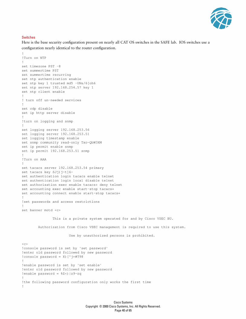
SwitchesHere is the base security configuration present on nearly all CAT OS switches in the SAFE lab. IOS switches use a
configuration nearly identical to the router configuration.!!Turn on NTP!set timezone PST -8set summertime PST set summertime recurringset ntp authentication enableset ntp key 1 trusted md5 -UN&/6[oh6set ntp server 192.168.254.57 key 1set ntp client enable!! turn off un-needed services!set cdp disableset ip http server disable!!turn on logging and snmp!set logging server 192.168.253.56set logging server 192.168.253.51set logging timestamp enableset snmp community read-only Txo~QbW3XMset ip permit enable snmpset ip permit 192.168.253.51 snmp!!Turn on AAA!set tacacs server 192.168.253.54 primaryset tacacs key SJj)j~t]6-set authentication login tacacs enable telnetset authentication login local disable telnetset authorization exec enable tacacs+ deny telnetset accounting exec enable start-stop tacacs+set accounting connect enable start-stop tacacs+!!set passwords and access restrictions!set banner motd <c>
This is a private system operated for and by Cisco VSEC BU.
Authorization from Cisco VSEC management is required to use this system.
Use by unauthorized persons is prohibited.
<c>!console password is set by 'set password'!enter old password followed by new password!console password = X)[^j+#T98!!enable password is set by 'set enable'!enter old password followed by new password!enable password = %Z<)|z9~zq!!the following password configuration only works the first time!
Cisco SystemsCopyright © 2000 Cisco Systems, Inc. All Rights Reserved.
Page 40 of 65

set password
X)[^j+#T98X)[^j+#T98set en ablecisco%Z<)|z9~zq%Z<)|z9~zq!!the above password configuration only works the first time!set logout 2set ip permit enable telnetset ip permit 192.168.253 .0 255.255.255.0 telnet
HostsHosts were patched with the latest fixes. HIDS was applied as well. The HIDS application used in the lab is ClickNet’s
Entercept application. More information is available at: http://www.clicknet.com
Management Module
Figure 29 Management Module: Detail
OTPServer
AccessControlServer
x6 TermServer(IOS)
To All DeviceConsole Ports
EncryptedIn-BandNetworkManagement
Out-of-BandNetworkManagement
x6 Switch
elDS-91
elOS-21
NetworkMonitoring
IDSDirector
Syslog 1
Syslog 2
SystemAdmin
Cisco SystemsCopyright © 2000 Cisco Systems, Inc. All Rights Reserved.
Page 41 of 65

Products UsedCisco Catalyst 3500XL Layer 2 switches (all switching)
Cisco 3640 IOS Router with Firewall Feature Set (eIOS-21)
Cisco 2511 IOS Router (terminal servers)
Cisco Secure Intrusion Detection System (CSIDS) sensor
RSA SecureID OTP Server
Cisco Secure Access Control Server
Cisco Works 2000
Cisco Secure Policy Manager
netForensics syslog analysis tool
ClickNet Entercept HIDS
EIOS-21The following configuration sets the default IOS Firewall parameters:ip inspect audit-trailip inspect max-incomplete low 150ip inspect max-incomplete high 250ip inspect one-minute low 100ip inspect one-minute high 200ip inspect udp idle-time 20ip inspect dns-timeout 3ip inspect tcp idle-time 1800ip inspect tcp finwait-time 3ip inspect tcp synwait-time 15ip inspect tcp max-incomplete host 40 block-time 0ip inspect name mgmt_fw tcp timeout 300ip inspect name mgmt_fw udpip inspect name mgmt_fw tftpip inspect name mgmt_fw httpip inspect name mgmt_fw fragment maximum 256 timeout 1ip audit notify logip audit po max-events 100
The following configuration sets up the encrypted in-band network management:crypto isakmp policy 1 encr 3des authentication pre-share group 2crypto isakmp key A%Xr)7,_) address 172.16.224.24 crypto isakmp key A%Xr)7,_) address 172.16.224.23 !crypto ipsec transform-set vpn_module_mgmt esp-3des esp-sha-hmac !crypto map mgmt1 100 ipsec-isakmp set peer 172.16.224.24 set transform-set vpn_module_mgmt match address 111crypto map mgmt1 200 ipsec-isakmp set peer 172.16.224.23 set transform-set vpn_module_mgmt match address 110access-list 110 permit ip 192.168.253.0 0.0.0.255 host 172.16.224.23access-list 110 permit udp 192.168.254.0 0.0.0.255 host 172.16.224.23access-list 111 permit ip 192.168.253.0 0.0.0.255 host 172.16.224.24access-list 111 permit udp 192.168.254.0 0.0.0.255 host 172.16.224.24
Cisco SystemsCopyright © 2000 Cisco Systems, Inc. All Rights Reserved.
Page 42 of 65

The following configuration defines inbound access control from the managed host network. Port 45000 is for CSIDS and
port 5000 is for Click Net’s HIDS.access-list 114 permit icmp 192.168.254.0 0.0.0.255 192.168.253.0 0.0.0.255 echo-replyaccess-list 114 permit udp 192.168.254.0 0.0.0.255 host 192.168.253.56 eq syslogaccess-list 114 permit udp 192.168.254.0 0.0.0.255 host 192.168.253.51 eq syslogaccess-list 114 permit udp 192.168.254.0 0.0.0.255 host 192.168.253.50 eq 45000access-list 114 permit tcp 192.168.254.0 0.0.0.255 host 192.168.253.50 eq 5000access-list 114 permit udp 192.168.254.0 0.0.0.255 host 192.168.253.53 eq tftpaccess-list 114 permit udp 192.168.254.0 0.0.0.255 host 192.168.254.57 eq ntpaccess-list 114 permit tcp 192.168.254.0 0.0.0.255 host 192.168.253.54 eq tacacsaccess-list 114 permit udp 192.168.254.0 0.0.0.255 host 192.168.253.54 eq 1645access-list 114 permit udp 192.168.254.0 0.0.0.255 host 192.168.253.52 eq syslogaccess-list 114 deny ip any any log
The following configuration defines inbound access control from the management host network:access-list 113 permit icmp 192.168.253.0 0.0.0.255 192.168.254.0 0.0.0.255access-list 113 permit icmp 192.168.253.0 0.0.0.255 host 192.168.253.57access-list 113 permit tcp 192.168.253.0 0.0.0.255 host 192.168.253.57 eq telnetaccess-list 113 permit tcp 192.168.253.0 0.0.0.255 192.168.254.0 0.0.0.255 eq telnetaccess-list 113 permit tcp 192.168.253.0 0.0.0.255 192.168.254.0 0.0.0.255 eq 443access-list 113 permit tcp 192.168.253.0 0.0.0.255 192.168.254.0 0.0.0.255 eq 22access-list 113 permit udp host 192.168.253.50 192.168.254.0 0.0.0.255 eq 45000access-list 113 permit tcp host 192.168.253.50 192.168.254.0 0.0.0.255 eq 5000access-list 113 permit udp host 192.168.253.51 192.168.254.0 0.0.0.255 eq snmpaccess-list 113 permit udp host 192.168.253.53 gt 1023 host 192.168.253.57 gt 1023access-list 113 permit udp 192.168.253.0 0.0.0.255 host 192.168.254.57 eq ntpaccess-list 113 permit tcp host 192.168.253.54 eq tacacs host 192.168.253.57 gt 1023access-list 113 permit icmp 192.168.253.0 0.0.0.255 host 172.16.224.23access-list 113 permit icmp 192.168.253.0 0.0.0.255 host 172.16.224.24access-list 113 permit tcp 192.168.253.0 0.0.0.255 host 172.16.224.23 eq telnetaccess-list 113 permit tcp 192.168.253.0 0.0.0.255 host 172.16.224.24 eq telnetaccess-list 113 permit udp host 192.168.253.51 host 172.16.224.23 eq snmpaccess-list 113 permit udp host 192.168.253.51 host 172.16.224.24 eq snmpaccess-list 113 deny ip any any log
The following configuration defines inbound access control from the production network. This access allows only encrypted
traffic, since that is the only communication allowed into the management module from the production network. The first
four lines define access for the encrypted traffic. After decryption, traffic must again pass through the access list in order to
be allowed into the management module.access-list 112 permit esp host 172.16.224.23 host 10.1.20.57access-list 112 permit esp host 172.16.224.24 host 10.1.20.57access-list 112 permit udp host 172.16.224.24 host 10.1.20.57 eq isakmpaccess-list 112 permit udp host 172.16.224.23 host 10.1.20.57 eq isakmpaccess-list 112 permit udp host 172.16.224.24 host 192.168.253.56 eq syslogaccess-list 112 permit udp host 172.16.224.23 host 192.168.253.56 eq syslogaccess-list 112 permit udp host 172.16.224.24 host 192.168.253.51 eq syslogaccess-list 112 permit udp host 172.16.224.23 host 192.168.253.51 eq syslogaccess-list 112 permit udp host 172.16.224.24 host 192.168.253.53 eq tftpaccess-list 112 permit udp host 172.16.224.23 host 192.168.253.53 eq tftpaccess-list 112 permit udp host 172.16.224.24 host 192.168.253.57 eq ntpaccess-list 112 permit udp host 172.16.224.23 host 192.168.253.57 eq ntpaccess-list 112 permit tcp host 172.16.224.24 host 192.168.253.54 eq tacacsaccess-list 112 permit tcp host 172.16.224.23 host 192.168.253.54 eq tacacsaccess-list 112 permit icmp host 172.16.224.24 192.168.253.0 0.0.0.255 echo-replyaccess-list 112 permit icmp host 172.16.224.23 192.168.253.0 0.0.0.255 echo-replyaccess-list 112 deny ip any any log
Cisco SystemsCopyright © 2000 Cisco Systems, Inc. All Rights Reserved.
Page 43 of 65
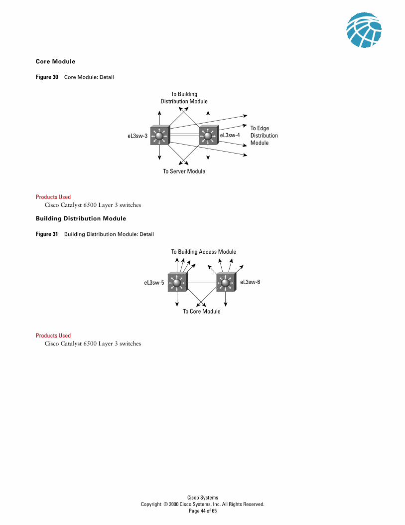
Core Module
Figure 30 Core Module: Detail
Products UsedCisco Catalyst 6500 Layer 3 switches
Building Distribution Module
Figure 31 Building Distribution Module: Detail
Products UsedCisco Catalyst 6500 Layer 3 switches
To BuildingDistribution Module
To EdgeDistributionModule
To Server Module
eL3sw-3 eL3sw-4
To Building Access Module
To Core Module
eL3sw-5 eL3sw-6
Cisco SystemsCopyright © 2000 Cisco Systems, Inc. All Rights Reserved.
Page 44 of 65

EL3SW-5The following configuration snapshot defines the Layer 3 access control between subnets in this module. VLAN 5 defines
the marketing subnet, VLAN 6 defines the R&D subnet, VLAN 7 defines the marketing IP phones, and VLAN 8 defines the
R&D IP phones.interface Vlan5 ip address 10.1.5.5 255.255.255.0 ip access-group 105 in!interface Vlan6 ip address 10.1.6.5 255.255.255.0 ip access-group 106 in!interface Vlan7 ip address 10.1.7.5 255.255.255.0 ip access-group 107 in!interface Vlan8 ip address 10.1.8.5 255.255.255.0 ip access-group 108 in!access-list 105 deny ip 10.1.5.0 0.0.0.255 10.1.6.0 0.0.0.255access-list 105 deny ip 10.1.5.0 0.0.0.255 10.1.7.0 0.0.0.255access-list 105 deny ip 10.1.5.0 0.0.0.255 10.1.8.0 0.0.0.255access-list 105 deny ip 10.1.5.0 0.0.0.255 10.1.16.0 0.0.0.255access-list 105 permit ip 10.1.5.0 0.0.0.255 anyaccess-list 105 deny ip any any logaccess-list 106 deny ip 10.1.6.0 0.0.0.255 10.1.5.0 0.0.0.255access-list 106 deny ip 10.1.6.0 0.0.0.255 10.1.7.0 0.0.0.255access-list 106 deny ip 10.1.6.0 0.0.0.255 10.1.8.0 0.0.0.255access-list 106 deny ip 10.1.6.0 0.0.0.255 10.1.15.0 0.0.0.255access-list 106 deny ip 10.1.6.0 0.0.0.255 10.1.16.0 0.0.0.255access-list 106 permit ip 10.1.6.0 0.0.0.255 anyaccess-list 106 deny ip any any logaccess-list 107 permit ip 10.1.7.0 0.0.0.255 10.1.8.0 0.0.0.255access-list 107 permit ip 10.1.7.0 0.0.0.255 10.1.16.0 0.0.0.255access-list 107 permit ip 10.1.7.0 0.0.0.255 host 10.1.11.50access-list 107 deny ip any any logaccess-list 108 permit ip 10.1.8.0 0.0.0.255 10.1.7.0 0.0.0.255access-list 108 permit ip 10.1.8.0 0.0.0.255 10.1.16.0 0.0.0.255access-list 108 permit ip 10.1.8.0 0.0.0.255 host 10.1.11.50access-list 108 deny ip any any log
Cisco SystemsCopyright © 2000 Cisco Systems, Inc. All Rights Reserved.
Page 45 of 65

Building Access Module
Figure 32 Building Access Module: Detail
Products UsedCisco Catalyst 4003 Layer 2 switches
Cisco IP Phone
EL2SW-11 and 12The following configuration snapshot show some of the VLAN settings on the Layer 2 switches in this module. Notice that
unneeded ports are disabled and set to a non-routable VLAN. Also, trunking is turned off on all ports except those
connecting to IP phones which use trunking for VLAN separation between phone and workstation.set vlan 5 2/5,2/17set vlan 6 2/6,2/18set vlan 99 2/34set vlan 999 2/1-3,2/7-16,2/19-33set port disable 2/7-33set trunk 2/1-34 offset trunk 2/4 on dot1q 1,5-8
Server Module
Figure 33 Server Module: Detail
Products UsedCisco Catalyst 6500 Layer 3 switches
Cisco Catalyst 6500 Intrusion Detection Blade
Cisco Call Manager
ClickNet Entercept HIDS
eL2sw-11 eL2sw-12
To Building Distribution Module
CorporateServer
To Core Module
eL3sw-1 eL3sw-2
InternalEmail
Dept.Server
CiscoCallManager
Cisco SystemsCopyright © 2000 Cisco Systems, Inc. All Rights Reserved.
Page 46 of 65

EL3SW-1 and 2The following configuration sets the private VLAN mappings for several of the ports within the same VLAN. This config
prevents the internal email server from communicating with the corporate server.! CAT OS Config!#private vlansset pvlan 11 437set pvlan 11 437 3/3-4,3/14set pvlan mapping 11 437 15/1!! MSFC Config !interface Vlan11 ip address 10.1.11.1 255.255.255.0 ip access-group 111 in no ip redirects
The following configuration sets the interface filtering on several of the interfaces in this module. This includes RFC 2827
filtering.interface Vlan11 ip address 10.1.11.1 255.255.255.0 ip access-group 111 in!interface Vlan15 ip address 10.1.15.1 255.255.255.0 ip access-group 115 in!interface Vlan16 ip address 10.1.16.1 255.255.255.0 ip access-group 116 in ip access-group 126 out!access-list 111 permit ip 10.1.11.0 0.0.0.255 anyaccess-list 111 deny ip any any logaccess-list 115 permit ip 10.1.15.0 0.0.0.255 anyaccess-list 115 deny ip any any logaccess-list 116 permit ip 10.1.16.0 0.0.0.255 10.1.7.0 0.0.0.255access-list 116 permit ip 10.1.16.0 0.0.0.255 10.1.8.0 0.0.0.255access-list 116 permit ip 10.1.16.0 0.0.0.255 10.1.11.0 0.0.0.255access-list 116 deny ip any any logaccess-list 126 permit ip 10.1.7.0 0.0.0.255 10.1.16.0 0.0.0.255access-list 126 permit ip 10.1.8.0 0.0.0.255 10.1.16.0 0.0.0.255access-list 126 permit ip 10.1.11.0 0.0.0.255 10.1.16.0 0.0.0.255
The following configuration sets up the capture port for the Cat 6000 IDS module:#module 4 : 2-port Intrusion Detection Systemset module name 4 set module enable 4set vlan 1 4/1set vlan 99 4/2set port name 4/1 Sniff-4set port name 4/2 CandC-4set trunk 4/1 nonegotiate dot1q 1-1005,1025-4094set security acl capture-ports 4/1
Cisco SystemsCopyright © 2000 Cisco Systems, Inc. All Rights Reserved.
Page 47 of 65

Edge Distribution Module
Figure 34 Edge Distribution Module: Detail
Products UsedCisco Catalyst 6500 Layer 3 switches
Corporate Internet Module
Figure 35 Corporate Internet Module: Detail
To e-CommerceModule
To CorporateInternet Module
To VPN/RemoteAccess ModuleTo
CoreModule
eL3sw-7
eL3sw-8
To WAN Module
ISP B
WEB/FTP SMTPDNS
elDS-81
ePIX-33
ePIX-31
elDS-84
elDS-85
elOS-22
To EdgeDistribution
URL Filtering
elOS-21
To VPN/RemoteAccess
elOS-24
elOS-23
ISP A
elDS-82
elDS-86 elDS-83
Cisco SystemsCopyright © 2000 Cisco Systems, Inc. All Rights Reserved.
Page 48 of 65
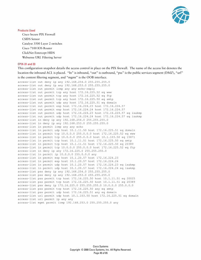
Products UsedCisco Secure PIX Firewall
CSIDS Sensor
Catalyst 3500 Layer 2 switches
Cisco 7100 IOS Router
ClickNet Entercept HIDS
Websense URL Filtering Server
EPIX-31 and 33This configuration snapshot details the access control in place on the PIX firewall. The name of the access list denotes the
location the inbound ACL is placed. “In” is inbound, “out” is outbound, “pss” is the public services segment (DMZ), “url”
is the content filtering segment, and “mgmt” is the OOB interface.access-list out deny ip any 192.168.254.0 255.255.255.0 access-list out deny ip any 192.168.253.0 255.255.255.0 access-list out permit icmp any any echo-reply access-list out permit tcp any host 172.16.225.52 eq www access-list out permit tcp any host 172.16.225.52 eq ftp access-list out permit tcp any host 172.16.225.50 eq smtp access-list out permit udp any host 172.16.225.51 eq domain access-list out permit esp host 172.16.224.23 host 172.16.224.57 access-list out permit esp host 172.16.224.24 host 172.16.224.57 access-list out permit udp host 172.16.224.23 host 172.16.224.57 eq isakmp access-list out permit udp host 172.16.224.24 host 172.16.224.57 eq isakmp access-list in deny ip any 192.168.254.0 255.255.255.0 access-list in deny ip any 192.168.253.0 255.255.255.0 access-list in permit icmp any any echo access-list in permit udp host 10.1.11.50 host 172.16.225.51 eq domain access-list in permit tcp 10.0.0.0 255.0.0.0 host 172.16.225.52 eq www access-list in permit tcp 10.0.0.0 255.0.0.0 host 10.1.103.50 eq 15871 access-list in permit tcp host 10.1.11.51 host 172.16.225.50 eq smtp access-list in permit tcp host 10.1.11.51 host 172.16.225.50 eq 20389 access-list in permit tcp 10.0.0.0 255.0.0.0 host 172.16.225.52 eq ftp access-list in deny ip any 172.16.225.0 255.255.255.0 access-list in permit ip 10.0.0.0 255.0.0.0 any access-list in permit esp host 10.1.20.57 host 172.16.224.23 access-list in permit esp host 10.1.20.57 host 172.16.224.24 access-list in permit udp host 10.1.20.57 host 172.16.224.23 eq isakmp access-list in permit udp host 10.1.20.57 host 172.16.224.24 eq isakmp access-list pss deny ip any 192.168.254.0 255.255.255.0 access-list pss deny ip any 192.168.253.0 255.255.255.0 access-list pss permit tcp host 172.16.225.50 host 10.1.11.51 eq 20025 access-list pss permit tcp host 172.16.225.50 host 10.1.11.51 eq 20389 access-list pss deny ip 172.16.225.0 255.255.255.0 10.0.0.0 255.0.0.0 access-list pss permit tcp host 172.16.225.50 any eq smtp access-list pss permit udp host 172.16.225.51 any eq domain access-list url permit udp host 10.1.103.50 host 172.16.225.51 eq domain access-list url permit ip any anyaccess-list mgmt permit icmp 192.168.253.0 255.255.255.0 any
Cisco SystemsCopyright © 2000 Cisco Systems, Inc. All Rights Reserved.
Page 49 of 65

EIOS-23 and 24This configuration snapshot details the hot standby router protocol (HSRP) commands on many routers using HSRP for high
availability.interface FastEthernet0/0 ip address 172.16.226.23 255.255.255.0 standby 2 timers 5 15 standby 2 priority 110 preempt delay 2 standby 2 authentication k&>9NG@6 standby 2 ip 172.16.226.100 standby 2 track ATM4/0 50
The following sets up the encrypted in-band network management link to the management module:crypto isakmp policy 1 encr 3des authentication pre-share group 2crypto isakmp key A%Xr)7,_) address 172.16.224.57 !crypto ipsec transform-set vpn_module_mgmt esp-3des esp-sha-hmac !crypto map mgmt1 100 ipsec-isakmp set peer 172.16.224.57 set transform-set vpn_module_mgmt match address 103
access-list 103 permit ip host 172.16.224.23 192.168.253.0 0.0.0.255access-list 103 permit udp host 172.16.224.23 192.168.254.0 0.0.0.255
The following ACL sits inbound from the enterprise network:access-list 112 permit udp host 172.16.224.57 host 172.16.224.23 eq isakmpaccess-list 112 permit esp host 172.16.224.57 host 172.16.224.23access-list 112 permit tcp 192.168.253.0 0.0.0.255 host 172.16.224.23 establishedaccess-list 112 permit udp 192.168.253.0 0.0.0.255 host 172.16.224.23 gt 1023access-list 112 permit tcp 192.168.253.0 0.0.0.255 host 172.16.224.23 eq telnetaccess-list 112 permit udp host 192.168.253.51 host 172.16.224.23 eq snmpaccess-list 112 permit udp host 192.168.254.57 host 172.16.224.23 eq ntpaccess-list 112 permit icmp any anyaccess-list 112 deny ip any host 172.16.224.23 logaccess-list 112 deny ip any host 172.16.226.23 logaccess-list 112 deny ip any host 172.16.145.23 logaccess-list 112 permit ip 172.16.224.0 0.0.0.255 anyaccess-list 112 permit ip 172.16.225.0 0.0.0.255 any
The following ACL sits inbound from the ISP. Note RFC 1918 filtering is not complete since these addresses are used as
production addresses in the lab. Actual networks should implement full RFC 1918 filtering.access-list 150 deny ip 10.0.0.0 0.255.255.255 anyaccess-list 150 deny ip 192.168.0.0 0.0.255.255 anyaccess-list 150 deny ip 172.16.224.0 0.0.7.255 anyaccess-list 150 permit ip any 172.16.224.0 0.0.7.255access-list 150 permit ip any 172.16.145.0 0.0.0.255access-list 150 permit esp any 172.16.226.0 0.0.0.255 fragmentsaccess-list 150 deny ip any any fragmentsaccess-list 150 deny ip any any log
Cisco SystemsCopyright © 2000 Cisco Systems, Inc. All Rights Reserved.
Page 50 of 65
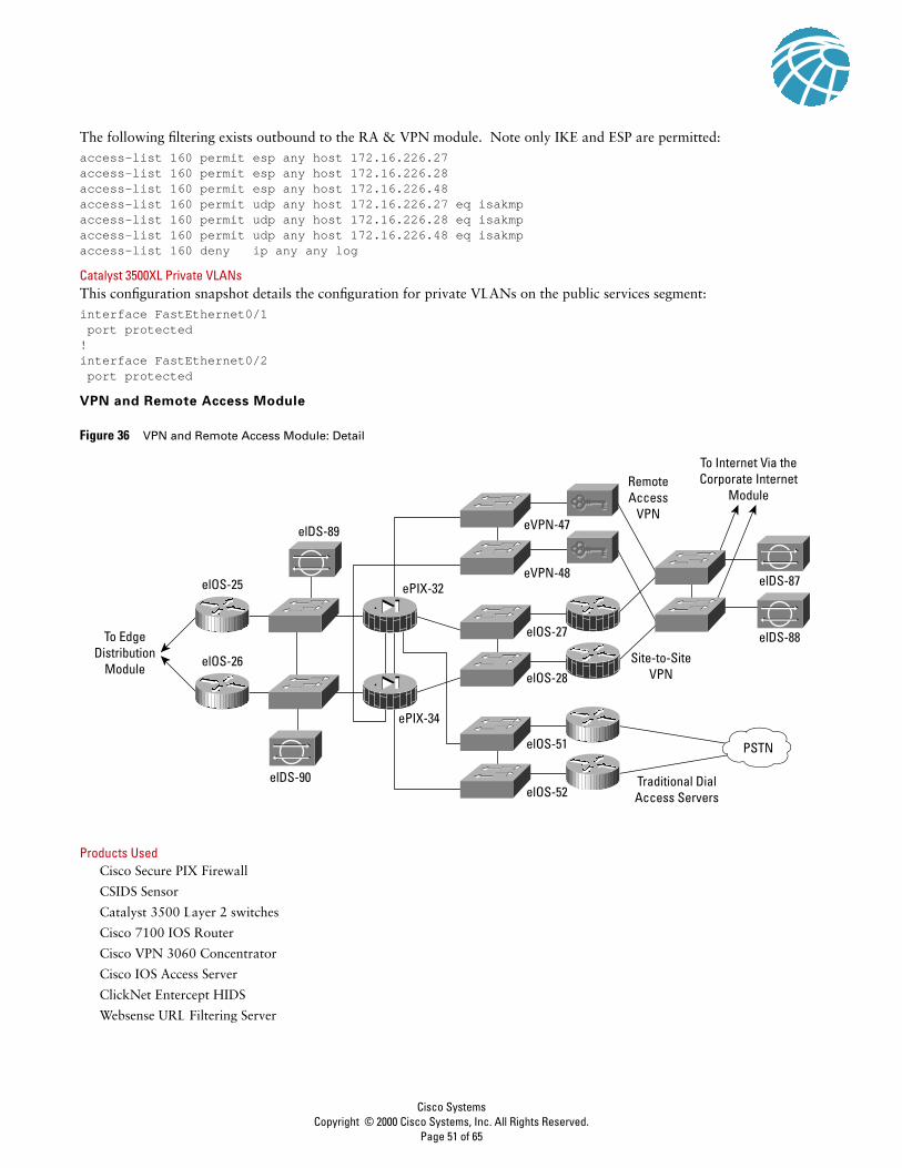
The following filtering exists outbound to the RA & VPN module. Note only IKE and ESP are permitted:access-list 160 permit esp any host 172.16.226.27access-list 160 permit esp any host 172.16.226.28access-list 160 permit esp any host 172.16.226.48access-list 160 permit udp any host 172.16.226.27 eq isakmpaccess-list 160 permit udp any host 172.16.226.28 eq isakmpaccess-list 160 permit udp any host 172.16.226.48 eq isakmpaccess-list 160 deny ip any any log
Catalyst 3500XL Private VLANsThis configuration snapshot details the configuration for private VLANs on the public services segment:interface FastEthernet0/1 port protected!interface FastEthernet0/2 port protected
VPN and Remote Access Module
Figure 36 VPN and Remote Access Module: Detail
Products UsedCisco Secure PIX Firewall
CSIDS Sensor
Catalyst 3500 Layer 2 switches
Cisco 7100 IOS Router
Cisco VPN 3060 Concentrator
Cisco IOS Access Server
ClickNet Entercept HIDS
Websense URL Filtering Server
elOS-25
elOS-27
elOS-51
elOS-52
elOS-28
elDS-88
elDS-87
elOS-26
elDS-89
elDS-90
To EdgeDistribution
Module
ePIX-34
eVPN-47
RemoteAccess
VPN
To Internet Via theCorporate Internet
Module
Traditional DialAccess Servers
Site-to-SiteVPN
eVPN-48ePIX-32
PSTN
Cisco SystemsCopyright © 2000 Cisco Systems, Inc. All Rights Reserved.
Page 51 of 65

EPIX-32 and 34This configuration snapshot details the access control in place on the PIX firewall. The name of the access list denotes the
location the inbound ACL is placed. “In” is inbound, “out” is the site-to-site VPN, “dun” is the PSTN dial-up, “ra” is the
remote access VPN, and “mgmt” is the OOB interface.access-list in deny ip any 192.168.253.0 255.255.255.0 access-list in deny ip any 192.168.254.0 255.255.255.0 access-list in permit icmp any any access-list in permit tcp 10.0.0.0 255.0.0.0 10.0.0.0 255.0.0.0 eq smtp access-list in permit tcp 10.0.0.0 255.0.0.0 10.0.0.0 255.0.0.0 eq pop3 access-list in permit tcp 10.0.0.0 255.0.0.0 10.0.0.0 255.0.0.0 eq wwwaccess-list in permit tcp 10.0.0.0 255.0.0.0 10.0.0.0 255.0.0.0 eq ftp access-list in permit udp 10.0.0.0 255.0.0.0 10.0.0.0 255.0.0.0 eq netbios-ns access-list in permit udp 10.0.0.0 255.0.0.0 10.0.0.0 255.0.0.0 eq netbios-dgm access-list in permit udp 10.0.0.0 255.0.0.0 10.0.0.0 255.0.0.0 eq domain access-list out deny ip any 192.168.253.0 255.255.255.0 access-list out deny ip any 192.168.254.0 255.255.255.0 access-list out permit icmp any any access-list out permit tcp 10.0.0.0 255.0.0.0 10.0.0.0 255.0.0.0 eq smtp access-list out permit tcp 10.0.0.0 255.0.0.0 10.0.0.0 255.0.0.0 eq pop3 access-list out permit tcp 10.0.0.0 255.0.0.0 10.0.0.0 255.0.0.0 eq www access-list out permit tcp 10.0.0.0 255.0.0.0 10.0.0.0 255.0.0.0 eq ftpaccess-list out permit udp 10.0.0.0 255.0.0.0 10.0.0.0 255.0.0.0 eq netbios-ns access-list out permit udp 10.0.0.0 255.0.0.0 10.0.0.0 255.0.0.0 eq netbios-dgm access-list out permit udp 10.0.0.0 255.0.0.0 10.0.0.0 255.0.0.0 eq domain access-list out permit tcp 10.0.0.0 255.0.0.0 172.16.255.0 255.255.255.0 eq wwwaccess-list out permit tcp 10.0.0.0 255.0.0.0 172.16.255.0 255.255.255.0 eq ftp access-list ra deny ip any 192.168.253.0 255.255.255.0 access-list ra deny ip any 192.168.254.0 255.255.255.0 access-list ra permit icmp any any access-list ra permit tcp 10.1.198.0 255.255.254.0 10.0.0.0 255.0.0.0 eq smtp access-list ra permit tcp 10.1.198.0 255.255.254.0 10.0.0.0 255.0.0.0 eq pop3 access-list ra permit tcp 10.1.198.0 255.255.254.0 10.0.0.0 255.0.0.0 eq www access-list ra permit tcp 10.1.198.0 255.255.254.0 10.0.0.0 255.0.0.0 eq ftpaccess-list ra permit udp 10.1.198.0 255.255.254.0 10.0.0.0 255.0.0.0 eq netbios-ns access-list ra permit udp 10.1.198.0 255.255.254.0 10.0.0.0 255.0.0.0 eq netbios-dgm access-list ra permit udp 10.1.198.0 255.255.254.0 10.0.0.0 255.0.0.0 eq domain access-list ra deny ip 10.1.198.0 255.255.254.0 10.0.0.0 255.0.0.0 access-list ra permit tcp 10.1.198.0 255.255.254.0 172.16.225.0 255.255.255.0 eq wwwaccess-list ra permit tcp 10.1.198.0 255.255.254.0 172.16.225.0 255.255.255.0 eq ftpaccess-list ra deny ip 10.1.198.0 255.255.254.0 172.16.224.0 255.255.248.0 access-list ra permit ip 10.1.198.0 255.255.254.0 any access-list dun deny ip any 192.168.253.0 255.255.255.0 access-list dun deny ip any 192.168.254.0 255.255.255.0 access-list dun permit icmp any any access-list dun permit tcp 10.1.196.0 255.255.254.0 10.0.0.0 255.0.0.0 eq smtp access-list dun permit tcp 10.1.196.0 255.255.254.0 10.0.0.0 255.0.0.0 eq pop3 access-list dun permit tcp 10.1.196.0 255.255.254.0 10.0.0.0 255.0.0.0 eq www access-list dun permit tcp 10.1.196.0 255.255.254.0 10.0.0.0 255.0.0.0 eq ftpaccess-list dun permit udp 10.1.196.0 255.255.254.0 10.0.0.0 255.0.0.0 eq netbios-ns access-list dun permit udp 10.1.196.0 255.255.254.0 10.0.0.0 255.0.0.0 eq netbios-dgm access-list dun permit udp 10.1.196.0 255.255.254.0 10.0.0.0 255.0.0.0 eq domain access-list dun deny ip 10.1.196.0 255.255.254.0 10.0.0.0 255.0.0.0 access-list dun permit tcp 10.1.196.0 255.255.255.0 172.16.225.0 255.255.255.0 eq wwwaccess-list dun permit tcp 10.1.196.0 255.255.255.0 172.16.225.0 255.255.255.0 eq ftp access-list dun deny ip 10.1.196.0 255.255.254.0 172.16.224.0 255.255.248.0 access-list dun permit ip 10.1.196.0 255.255.254.0 any access-list mgmt permit icmp 192.168.253.0 255.255.255.0 any
Cisco SystemsCopyright © 2000 Cisco Systems, Inc. All Rights Reserved.
Page 52 of 65
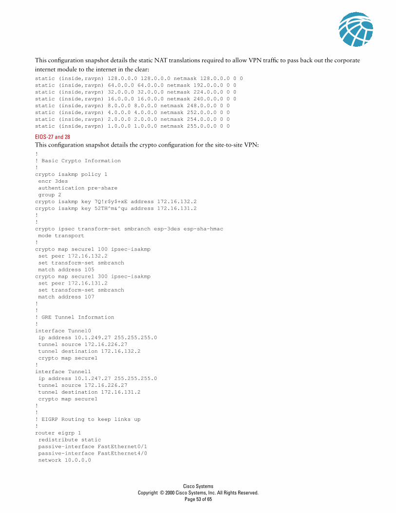
This configuration snapshot details the static NAT translations required to allow VPN traffic to pass back out the corporate
internet module to the internet in the clear:static (inside,ravpn) 128.0.0.0 128.0.0.0 netmask 128.0.0.0 0 0static (inside,ravpn) 64.0.0.0 64.0.0.0 netmask 192.0.0.0 0 0static (inside,ravpn) 32.0.0.0 32.0.0.0 netmask 224.0.0.0 0 0static (inside,ravpn) 16.0.0.0 16.0.0.0 netmask 240.0.0.0 0 0static (inside,ravpn) 8.0.0.0 8.0.0.0 netmask 248.0.0.0 0 0static (inside,ravpn) 4.0.0.0 4.0.0.0 netmask 252.0.0.0 0 0static (inside,ravpn) 2.0.0.0 2.0.0.0 netmask 254.0.0.0 0 0static (inside,ravpn) 1.0.0.0 1.0.0.0 netmask 255.0.0.0 0 0
EIOS-27 and 28This configuration snapshot details the crypto configuration for the site-to-site VPN:!! Basic Crypto Information!crypto isakmp policy 1 encr 3des authentication pre-share group 2crypto isakmp key 7Q!r$y$+xE address 172.16.132.2 crypto isakmp key 52TH^m&^qu address 172.16.131.2 !!crypto ipsec transform-set smbranch esp-3des esp-sha-hmac mode transport!crypto map secure1 100 ipsec-isakmp set peer 172.16.132.2 set transform-set smbranch match address 105crypto map secure1 300 ipsec-isakmp set peer 172.16.131.2 set transform-set smbranch match address 107!!! GRE Tunnel Information!interface Tunnel0 ip address 10.1.249.27 255.255.255.0 tunnel source 172.16.226.27 tunnel destination 172.16.132.2 crypto map secure1!interface Tunnel1 ip address 10.1.247.27 255.255.255.0 tunnel source 172.16.226.27 tunnel destination 172.16.131.2 crypto map secure1!!! EIGRP Routing to keep links up!router eigrp 1 redistribute static passive-interface FastEthernet0/1 passive-interface FastEthernet4/0 network 10.0.0.0
Cisco SystemsCopyright © 2000 Cisco Systems, Inc. All Rights Reserved.
Page 53 of 65

distribute-list 2 out distribute-list 2 in!! Crypto ACLs!access-list 105 permit gre host 172.16.226.27 host 172.16.132.2access-list 107 permit gre host 172.16.226.27 host 172.16.131.2!! Inbound ACLs from Internet!access-list 110 permit udp 172.16.0.0 0.0.255.255 host 172.16.226.27 eq isakmpaccess-list 110 permit esp 172.16.0.0 0.0.255.255 host 172.16.226.27access-list 110 permit gre 172.16.0.0 0.0.255.255 host 172.16.226.27access-list 110 deny ip any any log
WAN Module
Figure 37 WAN Module: Detail
Products UsedCisco 3640 IOS Router
EIOS-61The following configuration details the access control on the routers in the WAN module:!! Inbound from the WAN!access-list 110 deny ip any 192.168.253.0 0.0.0.255 logaccess-list 110 deny ip any 192.168.254.0 0.0.0.255 logaccess-list 110 permit ospf any anyaccess-list 110 permit ip 10.2.0.0 0.0.255.255 10.1.0.0 0.0.255.255access-list 110 permit ip 10.2.0.0 0.0.255.255 10.3.0.0 0.0.255.255access-list 110 permit ip 10.2.0.0 0.0.255.255 10.4.0.0 0.0.255.255access-list 110 permit ip 10.2.0.0 0.0.255.255 172.16.224.0 0.0.7.255access-list 110 deny ip any any log!! Inbound from the Campus!access-list 111 deny ip any 192.168.253.0 0.0.0.255 logaccess-list 111 deny ip any 192.168.254.0 0.0.0.255 logaccess-list 111 permit ospf any anyaccess-list 111 permit ip 10.1.0.0 0.0.255.255 10.2.0.0 0.0.255.255access-list 111 permit ip 10.3.0.0 0.0.255.255 10.2.0.0 0.0.255.255access-list 111 permit ip 10.4.0.0 0.0.255.255 10.2.0.0 0.0.255.255access-list 111 permit ip 172.16.224.0 0.0.7.255 10.2.0.0 0.0.255.255access-list 111 deny ip any any log
To EdgeDistribution
Module
elOS-61
elOS-62
FR/ATM
Cisco SystemsCopyright © 2000 Cisco Systems, Inc. All Rights Reserved.
Page 54 of 65

Appendix B: Network Security Primer
The Need for Network Security
The Internet is changing the way we work, live, play, and learn. These changes are occurring both in the ways that we
currently experience (e-commerce, real-time information access, e-learning, expanded communication options, and so forth),
and in ways we have yet to experience. Imagine a day when your enterprise can make all its telephone calls over the Internet
for free. Or perhaps on a more personal note, consider logging on to a daycare provider’s Web site to check how your child
is doing throughout the day. As a society, we are just beginning to unlock the potential of the Internet. But with the Internet’s
unparalleled growth comes unprecedented exposure of personal data, critical enterprise resources, government secrets, and
so forth. Every day hackers pose an increasing threat to these entities with several different types of attacks. These attacks,
outlined in the next section, have become both more prolific and easier to implement. There are two primary reasons for this
problem.
First is the ubiquity of the Internet. With millions of devices currently connected to the Internet, and millions more on the
way, a hacker’s access to vulnerable devices will continue to increase. The ubiquity of the Internet has also allowed hackers
to share knowledge on a global scale. A simple Internet search on the words “hack,” “crack,” or “phreak” yields thousands
of sites, many of which contain malicious code, or the means with which to use that code.
Second is the pervasiveness of easy-to-use operating systems and development environments. This factor has reduced the
overall ingenuity and knowledge required by hackers. A truly remarkable hacker can develop easy-to-use applications that
can be distributed to the masses. Several hacker tools that are available in the public domain merely require an IP address
or host name and a click of a mouse button to execute an attack.
Network Attack Taxonomy
Network attacks can be as varied as the systems that they attempt to penetrate. Some attacks are elaborately complex, while
others are performed unknowingly by a well-intentioned device operator. It is important to understand some of the inherent
limitations of the TCP/IP protocol when evaluating the types of attacks. When the Internet was formed, it linked various
government entities and universities to one another with the express purpose of facilitating learning and research. The
original architects of the Internet never anticipated the kind of widespread adoption the Internet has achieved today. As a
result, in the early days of the Internet Protocol (IP), security was not designed into the specification. For this reason, most
IP implementations are inherently insecure. Only after many years and thousands of Requests for Comments (RFCs), do we
have the tools to begin to deploy IP securely. Because specific provisions for IP security were not designed from the onset, it
is important to augment IP implementations with network security practices, services, and products to mitigate the inherent
risks of the Internet Protocol. The following is a brief discussion of the types of attacks commonly seen on IP networks and
how these attacks can be mitigated.
Packet SniffersA packet sniffer is a software application that uses a network adapter card in promiscuous mode (a mode in which the
network adapter card sends all packets received on the physical network wire to an application for processing) to capture all
network packets that are sent across a particular collision domain. Sniffers are used legitimately in networks today to aid in
troubleshooting and traffic analysis. However, because several network applications send data in clear text (telnet, FTP,
SMTP, POP3, and so forth), a packet sniffer can provide meaningful and often sensitive information, such as usernames and
passwords.
One serious problem with acquiring usernames and passwords is that users often reuse their login names and passwords
across multiple applications and systems. In fact, many users employ a single password for access to all accounts and
applications. If an application is run in client-server mode and authentication information is sent across the network in clear
text, then it is likely that this same authentication information can be used to gain access to other corporate or external
Cisco SystemsCopyright © 2000 Cisco Systems, Inc. All Rights Reserved.
Page 55 of 65

resources. Because hackers know and use human characteristics (attack methods known collectively as social engineering
attacks), such as using a single password for multiple accounts, they are often successful in gaining access to sensitive
information. In a worst-case scenario, a hacker gains access to a system-level user account, which the hacker uses to create
a new account that can be used at any time as a back door to break into a network and its resources.
You can mitigate the threat of packet sniffers in several ways:
• Authentication – Using strong authentication is a first option for defense against packet sniffers. Strong authentication
can be broadly defined as a method of authenticating users that cannot easily be circumvented. A common example of
strong authentication is one-time-passwords (OTPs). An OTP is a type of two-factor authentication. Two-factor
authentication involves using something you have combined with something you know. Automated teller machines (ATMs)
use two-factor authentication. A customer needs both an ATM card and a personal identification number (PIN) to make
transactions. With OTP you need a PIN and your token card to authenticate to a device or software application. A token
card is a hardware or software device that generates new, seemingly random, passwords at specified intervals (usually 60
seconds). A user combines that random password with a PIN to create a unique password that only works for one instance
of authentication. If a hacker learns that password by using a packet sniffer, the information is useless because the
password has already expired. Note that this mitigation technique is effective only against a sniffer implementation that is
designed to grab passwords. Sniffers deployed to learn sensitive information (such as mail messages) will still be ineffective.
• Switched infrastructure – Another method to counter the use of packet sniffers in your environment is to deploy a switched
infrastructure. For example if an entire organization deploys switched Ethernet, hackers can only gain access to the traffic
that flows on the specific port to which they connect. A switched infrastructure obviously does not eliminate the threat of
packet sniffers, but it can greatly reduce their effectiveness.
• Anti-sniffer tools – A third method used against sniffers is to employ software and hardware designed to detect the use of
sniffers on a network. Such software and hardware does not completely eliminate the threat, but like many network
security tools, they are part of the overall system. These so-called “anti-sniffers” detect changes in the response time of
hosts to determine if the hosts are processing more traffic than their own. One such network security software tool, which
is available from LOpht Heavy Industries, is called AntiSniff™. For more information, refer to the URL http://
www.l0pht.com/antisniff/
• Cryptography – The most effective method for countering packet sniffers does not prevent or detect packet sniffers, but
rather renders them irrelevant. If a communication channel is cryptographically secure, the only data a packet sniffer will
detect is cipher text (a seemingly random string of bits) and not the original message. Cisco’s deployment of network-level
cryptography is based on IP Security (IPSec). IPSec is a standard method for networking devices to communicate privately
using IP. Other cryptographic protocols for network management include Secure Shell (SSH) and Secure Sockets Layer
(SSL).
IP SpoofingAn IP spoofing attack occurs when a hacker inside or outside a network pretends to be a trusted computer. A hacker can do
this in one of two ways. The hacker either uses an IP address that is within the range of trusted IP addresses for a network
or an authorized external IP address that is trusted and to which access is provided to specified resources on a network. IP
spoofing attacks are often a launch point for other attacks. The classic example is to launch a DoS attack using spoofed
source addresses to hide the hacker’s identity.
Normally, an IP spoofing attack is limited to the injection of malicious data or commands into an existing stream of data
that is passed between a client and server application or a peer-to-peer network connection. To enable bidirectional
communication, the hacker must change all routing tables to point to the spoofed IP address. Another approach hackers
sometimes take is to simply not worry about receiving any response from the applications. If a hacker tries to obtain a
sensitive file from a system, application responses are unimportant.
Cisco SystemsCopyright © 2000 Cisco Systems, Inc. All Rights Reserved.
Page 56 of 65

However, if a hacker manages to change the routing tables to point to the spoofed IP address, the hacker can receive all the
network packets that are addressed to the spoofed address and reply just as any trusted user can.
The threat of IP spoofing can be reduced, but not eliminated, through the following measures.
Access control – The most common method for preventing IP spoofing is to properly configure access control. To reduce the
effectiveness of IP spoofing, configure access control to deny any traffic from the external network that has a source address
that should reside on the internal network. Note that this only helps prevent spoofing attacks if the internal addresses are
the only trusted addresses. If some external addresses are trusted, this method is not effective.
RFC 2827 filtering – You can also prevent a network’s users from spoofing other networks (and be a good ’Net citizen at
the same time) by preventing any outbound traffic on your network that does not have a source address in your organization’s
own IP range. Your ISP can also implement this type of filtering, which is collectively referred to as RFC 2827 filtering. This
filtering denies any traffic that does not have the source address that was expected on a particular interface. For example, if
an ISP is providing a connection to the IP address 15.1.1.0/24, the ISP could filter traffic so that only traffic sourced from
address 15.1.1.0/24 can enter the ISP router from that interface. Note that unless all ISPs implement this type of filtering,
its effectiveness is significantly reduced. Also, the further you get from the devices you want to filter, the more difficult it
becomes to do that filtering at a granular level. For example, performing RFC 2827 filtering at the access router to the
Internet requires that you allow your entire major network number (that is, 10.0.0.0/8) to traverse the access router. If you
peform filtering at the distribution layer, as in this architecture, you can achieve more specific filtering (that is, 10.1.5.0/24).
The most effective method for mitigating the threat of IP spoofing is the same as the most effective method for mitigating the
threat of packet sniffers: namely eliminating its effectiveness. IP spoofing can function correctly only when devices use IP
address-based authentication. Therefore, if you use additional authentication methods, IP spoofing attacks are irrelevant.
Cryptographic authentication is the best form of additional authentication, but when that is not possible, strong two-factor
authentication using OTP can also be effective.
Denial of ServiceCertainly the most publicized form of attack, denial of service (DoS) attacks are also among the most difficult to completely
eliminate. Even among the hacker community, DoS attacks are regarded as trivial and considered bad form because they
require so little effort to execute. Still, because of their ease of implementation and potentially significant damage, DoS
attacks deserve special attention from security administrators. If you are interested in learning more about DoS attacks,
researching the methods employed by some of the better known attacks can be useful. These attacks include the following:
• TCP SYN Flood
• Ping of Death
• Tribe Flood Network (TFN) and Tribe Flood Network 2000 (TFN2K)
• Trinco
• Stacheldraht
• Trinity
Another excellent source on the topic of security is the Computer Emergency Response Team (CERT). They have published
an excellent paper on dealing with DoS attacks which you can find at the following URL: http://www.cert.org/tech_tips/
denial_of_service.html
DoS attacks are different from most other attacks because they are generally not targeted at gaining access to your network
or the information on your network. These attacks focus on making a service unavailable for normal use, which is typically
accomplished by exhausting some resource limitation on the network or within an operating system or application.
Cisco SystemsCopyright © 2000 Cisco Systems, Inc. All Rights Reserved.
Page 57 of 65

When involving specific network server applications, such as a Web server or an FTP server, these attacks can focus on
acquiring and keeping open all the available connections supported by that server, effectively locking out valid users of the
server or service. DoS attacks can also be implemented using common Internet protocols, such as TCP and Internet Control
Message Protocol (ICMP). Most DoS attacks exploit a weakness in the overall architecture of the system being attacked
rather than a software bug or security hole. However, some attacks compromise the performance of your network by
flooding the network with undesired, and often useless, network packets and by providing false information about the status
of network resources. This type of attack is often the most difficult to prevent as it requires coordination with your upstream
network provider. If traffic meant to consume your available bandwidth is not stopped there, denying it at the point of entry
into your network will do little good because your available bandwidth has already been consumed. When this type of attack
is launched from many different systems at the same time it is often referred to as a distributed denial of service attack
(DDoS).
The threat of Denial of Service attacks can be reduced through the following three methods:
• Anti-spoof features – Proper configuration of anti-spoof features on your routers and firewalls can reduce your risk. This
includes RFC 2827 filtering at a minimum. If hackers can’t mask their identities, they might not attack.
• Anti-DoS features – Proper configuration of anti-DoS features on routers and firewalls can help limit the effectiveness of
an attack. These features often involve limits on the amount of half-open connections that a system allows open at any
given time.
• Traffic rate limiting – An organization can implement traffic rate limiting with your ISP. This type of filtering limits the
amount of nonessential traffic that crosses network segments to a certain rate. A common example is to limit the amount
of ICMP traffic allowed into a network because it is used only for diagnostic purposes. ICMP-based (D)DoS attacks are
common.
Password AttacksHackers can implement password attacks using several different methods, including brute-force attacks, Trojan horse
programs, IP spoofing, and packet sniffers. Although packet sniffers and IP spoofing can yield user accounts and passwords,
password attacks usually refer to repeated attempts to identify a user account and/or password. These repeated attempts are
called brute-force attacks.
Often, a brute-force attack is performed using a program that runs across the network and attempts to log in to a shared
resource, such as a server. When hackers successfully gain access to resources, they have the same rights as the users whose
accounts have been compromised to gain access to those resources. If the compromised accounts have sufficient privileges,
the hackers can create back doors for future access without concern for any status and password changes to the compromised
user accounts.
Another problem exists whereby users have the same (possibly strong) password on every system they connect to. Often, this
includes personal systems, corporate systems, and systems on the Internet. Because that password is only as secure as the
most weakly administered host that contains it, if that host is compromised hackers have a whole range of hosts on which
they can try the same password.
You can most easily eliminate password attacks by not relying on plain-text passwords in the first place. Using OTP and/or
cryptographic authentication can virtually eliminate the threat of password attacks. Unfortunately, not all applications,
hosts, and devices support these authentication methods. When standard passwords are used, it is important to choose a
password that is difficult to guess. Passwords should be at least eight characters long and contain uppercase letters, lower
case letters, numbers, and special characters (#%$ and so forth). The best passwords are randomly generated but are very
difficult to remember, often leading users to writing write their passwords down.
Cisco SystemsCopyright © 2000 Cisco Systems, Inc. All Rights Reserved.
Page 58 of 65

Several advances have been made relative to password maintenance both for the user and the administrator. Software
applications are now available that encrypt a list of passwords to be stored on a handheld computer. This allows the user to
remember only one complex password and have the remaining passwords stored securely within the application. From the
standpoint of the administrator, several methods exist to brute-force attack your own users’ passwords. One such method
involves a tool used by the hacker community called L0phtCrack. L0phtCrack brute-force attacks Windows NT passwords
and can point out when a user has chosen a password that is very easy to guess. For more information, refer to the following
URL: http://www.l0pht.com/l0phtcrack/
Man-in-the-Middle AttacksA man-in-the-middle attack requires that the hacker have access to network packets that come across a network. An example
of such a configuration could be someone who is working for an ISP, who has access to all network packets transferred
between his employer’s network and any other network. Such attacks are often implemented using network packet sniffers
and routing and transport protocols. The possible uses of such attacks are theft of information, hijacking of an ongoing
session to gain access to private network resources, traffic analysis to derive information about a network and its users, denial
of service, corruption of transmitted data, and introduction of new information into network sessions.
Man-in-the-middle attacks can be effectively mitigated only through the use of cryptography. If someone hijacks data in the
middle of a cryptographically private session, all the hacker will see is cipher text and not the original message. Note that if
a hacker can learn information about the cryptographic session (such as the session key) man-in-the-middle attacks are still
possible.
Cisco SystemsCopyright © 2000 Cisco Systems, Inc. All Rights Reserved.
Page 59 of 65

Application Layer AttacksApplication layer attacks can be implemented using several different methods. One of the most common methods is
exploiting well-known weaknesses in software that are commonly found on servers, such as sendmail, HTTP, and FTP. By
exploiting these weaknesses, hackers can gain access to a computer with the permissions of the account running the
application, which is usually a privileged system-level account. These application layer attacks are often widely publicized in
an effort to allow administrators to rectify the problem with a patch. Unfortunately, many hackers also subscribe to these
same mailing lists, which results in their learning about the attack at the same time (if they haven’t discovered it already).
The primary problem with application-layer attacks is that they often use ports that are allowed through a firewall. For
example, a hacker executing a known vulnerability against a Web server often uses TCP port 80 in the attack. Because the
Web server serves pages to users, a firewall needs to allow access on that port. From a firewall’s perspective, it is merely
standard port 80 traffic.
Application layer attacks can never be completely eliminated. New vulnerabilities are always being discovered and
publicized to the Internet community. The best way to reduce your risk is by practicing good system administration. The
following are a few measures you can take to reduce your risks:
• Read OS and network log files and/or have them analyzed by log analysis applications
• Subscribe to mailing lists that publicize vulnerabilities such as Bugtraq (http://www.securityfocus.com) and the CERT
(http://www.cert.org)
• Keep your OS and applications current with the latest patches
• In addition to proper system administration, using Intrusion Detection Systems (IDSs) can aid in this effort. There are two
complementary IDS technologies:
• Network-based IDS (NIDS) operates by watching all packets traversing a particular collision domain. When NIDS sees a
packet or series of packets that match a known or suspect attack, it can flag an alarm and/or terminate the session.
• Host-based IDS (HIDS) operates by inserting agents into the host to be protected. It is then concerned only with attacks
generated against that one host.
• IDS systems operate by using attack signatures. Attack signatures are the profile for a particular attack or kind of attack.
They specify certain conditions that must be met before traffic is deemed to be an attack. In the physical world, IDS can be
most closely compared to an alarm system or security camera. IDS system’s greatest limitation is the amount of
false-positive alarms a particular system generates. Tuning IDS to prevent such false alarms is critical to the proper
operation of IDS in a network.
Network ReconnaissanceNetwork Reconnaissance refers to the overall act of learning information about a target network by using publicly available
information and applications. When hackers attempt to penetrate a particular network, they often need to learn as much
information as possible about the network before launching attacks. This can take the form of DNS queries, ping sweeps,
and port scans. DNS queries can reveal such information as who owns a particular domain and what addresses have been
assigned to that domain. Ping sweeps of the addresses revealed by the DNS queries can present a picture of the live hosts in
a particular environment. After such a list is generated, port scanning tools can cycle through all well-known ports to provide
a complete list of all services running on the hosts discovered by the ping sweep. Finally, the hackers can examine the
characteristics of the applications are running on the hosts. This can lead to specific information that is useful when the
hacker attempts to compromise that service.
Network recon cannot be prevented entirely. If ICMP echo and echo-reply is turned off on edge routers, for example, ping
sweeps can be stopped, but at the expense of network diagnostic data. However, port scans can easily be run without full
ping sweeps; they simply take longer because they need to scan IP addresses that might not be live. IDS at the network and
Cisco SystemsCopyright © 2000 Cisco Systems, Inc. All Rights Reserved.
Page 60 of 65

host levels can usually notify an administrator when a reconnaissance gathering attack is underway. This allows the
administrator to better prepare for the coming attack or to notify the ISP who is hosting the system that is launching the
reconnaissance probe.
Trust ExploitationWhile not an attack in and of itself, trust exploitation refers to an attack where an individual takes advantage of a trust
relationship within a network. The classic example is a perimeter network connection from a corporation. These network
segments often house DNS, SMTP, and HTTP servers. Because they all reside on the same segment, a compromise of one
system can lead to the compromise of other systems because they might trust other systems attached to their same network.
Another example is a system on the outside of a firewall that has a trust relationship with a system on the inside of a firewall.
When the outside system is compromised, it can leverage that trust relationship to attack the inside network.
You can mitigate trust exploitation-based attacks through tight constraints on trust levels within a network. Systems on the
outside of a firewall should never be absolutely trusted by systems on the inside of a firewall. Such trust should be limited to
specific protocols and should be authenticated by something other than an IP address where possible.
Port RedirectionPort Redirection attacks are a type of trust exploitation attack that uses a compromised host to pass traffic through a firewall
that would other wise be dropped. Consider a firewall with three interfaces and a host on each interface. The host on the
outside can reach the host on the public services segment (commonly referred to as a DMZ), but not the host on the inside.
The host on the public services segment can reach the host on both the outside and the inside. If hackers were able to
compromise the public services segment host, they could install software to redirect traffic from the outside host directly to
the inside host. Though neither communication violates the rules implemented in the firewall, the outside host has now
achieved connectivity to the inside host through the port redirection process on the public services host. An example of an
application that can provide this type of access is netcat. For more information, refer to the following URL: http://
www.avian.org
Port redirection can primarily be mitigated through the use of proper trust models (as mentioned earlier). Assuming a system
under attack, host-based IDS can help detect and prevent a hacker installing such utilities on a host.
Unauthorized AccessWhile not a specific type of attack, unauthorized access attacks refer to the majority of attacks executed in networks today.
In order for someone to brute-force a telnet login, they must first get the telnet prompt on a system Upon connection to the
telnet port, a message might indicate: “authorization required to use this resource.” If the hacker continues to attempt access,
his actions become “unauthorized”. These kinds of attacks can be initiated both on the outside and inside of a network.
Mitigation techniques for unauthorized access attacks are very simple. They involve reducing or eliminating the ability of a
hacker to gain access to a system using an unauthorized protocol. An example would be preventing hackers from having
access to the telnet port on a server that needs to provide Web services to the outside. If a hacker cannot reach that port, it
is very difficult to attack it. The primary function of a firewall in a network is to prevent simple unauthorized access attacks.
Virus and Trojan Horse ApplicationsThe primary vulnerabilities for end-user workstations are viruses and Trojan horse attacks. Viruses refer to malicious
software that is attached to another program to execute a particular unwanted function on a user’s workstation. An example
of a virus is a program that is attached to command.com (the primary interpreter for windows systems) which deletes certain
files and infects any other versions of command.com that it can find. A Trojan horse is different only in that the entire
application was written to look like something else, when in fact it is an attack tool. An example of a Trojan horse is a
Cisco SystemsCopyright © 2000 Cisco Systems, Inc. All Rights Reserved.
Page 61 of 65

software application that runs a simple game on the user’s workstation. While the user is occupied with the game, the Trojan
horse mails a copy of itself to every user in the user’s address book. Then other users get the game and play it, thus spreading
the Trojan horse.
These kinds of applications can be contained through the effective use of anti-virus software at the user level and potentially
at the network level. Anti-virus software can detect most viruses and many Trojan horse applications and prevent them from
spreading in the network. Keeping up-to-date with the latest developments in these sorts of attacks can also lead to a more
effective posture against these attacks. As new virus or Trojan applications are released, enterprises need to keep up-to-date
with the latest anti-virus software, and application versions.
What Is a “Security Policy”?
A security policy can be as simple as an acceptable use policy for network resources or can be several hundred pages in length
and detail every element of connectivity and associated policies. Although somewhat narrow in scope, RFC 2196 suitably
defines a security policy as follows:
“A security policy is a formal statement of the rules by which people who are given access to an organization’s technology
and information assets must abide.”
This document does not attempt to go into detail on the development of a security policy. RFC 2196 has some good
information available on the subject, and numerous locations on the Web have example policies and guidelines. The
following Web pages may assist the interested reader:
• RFC 2196 “Site Security Handbook” http://www.ietf.org/rfc/rfc2196.txt
• A sample security policy for the University of Illinois http://www.aits.uillinois.edu/security/securestandards.html
• Design and Implementation of the Corporate Security Policyhttp://www.knowcisco.com/content/1578700434/ch06.shtml
The Need for a Security Policy
It is important to understand that network security is an evolutionary process. No one product can make an organization
“secure”. True network security comes from a combination of products and services, combined with a comprehensive
security policy and a commitment to adhere to that policy from the top of the organization down. In fact, a properly
implemented security policy without dedicated security hardware can be more effective at mitigating the threat to enterprise
resources than a comprehensive security product implementation without an associated policy.
Appendix C: Architecture Taxonomy
Application Server – Provides application services directly or indirectly for enterprise end-users. Services can include:
work-flow, general office, and security applications.
Firewall (Stateful) – Stateful packet filtering device which maintain state tables for IP-based protocols. Traffic is only allowed
to cross the firewall if it conforms to the access-control filters defined, or if it is part of an already established session in the
state table.
Host IDS – Host Intrusion Detection System is a software application that monitors activity on an individual host.
Monitoring techniques can include validating operating system and application calls, checking log files, file system
information and network connections.
Network IDS – Network Intrusion Detection System. Typically used in a non-disruptive manner, this device captures traffic
on a LAN segment and tries to match the real-time traffic against known attack signatures. Signatures range from atomic
(single packet and direction) signatures to composite (multipacket) signatures requiring state tables and Layer 7 application
tracking.
IOS Firewall – A stateful packet filtering firewall running natively on Cisco IOS (Internetwork Operating System).
Cisco SystemsCopyright © 2000 Cisco Systems, Inc. All Rights Reserved.
Page 62 of 65

IOS Router – A wide spectrum of flexible network devices, which provide many routing and security services for all
performance requirements. Most devices are modular and have a range of LAN and WAN physical interfaces.
Layer 2 Switch – Provides bandwidth and VLAN services to network segments at the Ethernet level. Typically these devices
offer 10/100 individual switched ports, Gigabit Ethernet uplinks, VLAN trunking, and L2 filtering features.
Layer 3 Switch – Provides similar high throughput functions of a Layer 2 switch with added routing, QoS, and security
features. These switches often has the capability of special function processors.
Management Server – Provides network management services for the operators of enterprise networks. Services can include:
general configuration management, monitoring of network security devices, and operation of the security functions.
SMTP Content Filtering Server – An application typically running on an external SMTP server which monitors the content
(including attachments) of incoming and outgoing mail in order to decide whether that mail is authorized to be forwarded
as is, altered and forwarded, or dropped.
URL Filtering Server – An application typically running on a standalone server which monitors URL requests forwarded to
it by a network device and informs the network device whether the request should be forwarded on to the Internet. This
allows an enterprise to implement a security policy dictating what categories of Internet sites are unauthorized.
VPN Termination device – Terminates IPSec tunnels for either site-to-site or remote-access VPN connections. The device
should provide additional services in order to offer the same network functionality as a classic WAN or dial-in connection.
Workstation or User Terminal – Any device on the network which is used directly by the end-user. This includes PCs, IP
phones, wireless devices, and so forth.
Diagram Legend
Router Router with FirewallFeature Set
NetworkIntrusion Detection
System Sensor
Layer 3 Switchwith Intrusion
Detection Module
Layer 3 Switch
Firewall
Layer 2 SwitchVPN
ConcentratorIP TelephonyCall Manager
Workstation IP TelephoneManagementWorkstation
Cisco SystemsCopyright © 2000 Cisco Systems, Inc. All Rights Reserved.
Page 63 of 65

References
RFCs
RFC 2196 “Site Security Handbook” – http://www.ietf.org/rfc/rfc2196.txt
RFC 1918 “Address Allocation for Private Internets” – http://www.ietf.org/rfc/rfc1918.txt
RFC 2827 “Network Ingress Filtering: Defeating Denial of Service Attacks which employ IP Source Address Spoofing” –
http://www.ietf.org/rfc/rfc2827.txt
Miscellaneous References
“Improving Security on Cisco Routers” – http://www.cisco.com/warp/customer/707/21.html
“VLAN Security Test Report” – http://www.sans.org/newlook/resources/IDFAQ/vlan.htm
“AntiSniff” – http://www.l0pht.com/antisniff/
“L0phtCrack” – http://www.l0pht.com/l0phtcrack/
“Denial of Service Attacks” – http://www.cert.org/tech_tips/denial_of_service.html
“Computer Emergency Response Team” – http://www.cert.org
“Security Focus (Bugtraq)” – http://www.securityfocus.com
“Avian Research (netcat)” – http://www.avian.org
“University of Illinois Security Policy” – http://www.aits.uillinois.edu/security/securestandards.html
“Design and Implementation of the Corporate Security Policy” – http://www.knowcisco.com/content/1578700434/
ch06.shtml
Partner Product References
ClickNet Entercept Host-Based IDS – http://www.clicknet.com
RSA SecureID OTP System – http://www.rsasecurity.com/products/securid/
Content Technologies MIMESweeper Email Filtering System – http://www.contenttechnologies.com
Websense URL Filtering – http://www.websense.com/products/integrations/ciscopix.cfm
netForensics Syslog Analysis – http://www.netforensics.com/
Acknowledgments
The authors would like to publicly thank all the individuals who contributed to the SAFE architecture and the writing of this
document. Certainly, the successful completion of this architecture would not have been possible without the valuable input
and review feedback from all of the Cisco employees both in corporate headquarters and in the field. In addition, many
individuals contributed to the lab implementation and validation of the architecture. The core of this group included of
Roland Saville, Floyd Gerhardt, Majid Saee, Mark Doering, Charlie Stokes, Tom Hunter, Kevin McCormick and Casey
Smith. Thank you all for your special effort.
Cisco SystemsCopyright © 2000 Cisco Systems, Inc. All Rights Reserved.
Page 64 of 65

Copyright © 2000, Cisco Systems, Inc. All rights reserved. Cisco, Cisco IOS, Cisco Systems, and the Cisco Systems logo are registered trademarks of Cisco Systems, Inc. or its affiliates in the U.S. and certainother countries. All other brands, names, or trademarks mentioned in this document or Web site are the property of their respective owners. The use of the word partner does not imply a partnershiprelationship between Cisco and any other company. (0008R)
DA/102700
Cisco Systems has more than 190 offices in the following countries. Addresses, phone numbers, and fax numbers are listed on the
C i s c o . c o m W e b s i t e a t w w w . c i s c o . c o m / g o / o f f i c e s .
Argentina • Australia • Austria • Belgium • Brazil • Bulgaria • Canada • Chile • China • Colombia • Costa Rica • Croatia • Czech Republic • Denmark • Dubai, UAEFinland • France • Germany • Greece • Hong Kong • Hungary • India • Indonesia • Ireland • Israel • Italy • Japan • Korea • Luxembourg • Malaysia • Mexico • TheNetherlands • New Zealand • Norway • Peru • Philippines • Poland • Portugal • Puerto Rico • Romania • Russia • Saudi Arabia • Scotland • Singapore • SlovakiaSlovenia • South Africa • Spain • Sweden • Switzerland • Taiwan • Thailand • Turkey • Ukraine • United Kingdom • United States • Venezuela • Vietnam • Zimbabwe
Corporate HeadquartersCisco Systems, Inc.170 West Tasman DriveSan Jose, CA 95134-1706USAwww.cisco.comTel: 408 526-4000
800 553-NETS (6387)Fax: 408 526-4100
European HeadquartersCisco Systems Europe11, Rue Camille Desmoulins92782 Issy Les Moulineaux Cedex 9Francewww.cisco.comTel: 33 1 58 04 60 00Fax: 33 1 58 04 61 00
Americas HeadquartersCisco Systems, Inc.170 West Tasman DriveSan Jose, CA 95134-1706USAwww.cisco.comTel: 408 526-7660Fax: 408 527-0883
Asia Pacific HeadquartersCisco Systems Australia, Pty., LtdLevel 17, 99 Walker StreetNorth SydneyNSW 2059 Australiawww.cisco.comTel: +61 2 8448 7100Fax: +61 2 9957 4350