Securing Modern Substations With an Open Standard Network ...
23
Securing Modern Substations With an Open Standard Network Security Solution Dwight Anderson Schweitzer Engineering Laboratories, Inc. Presented at the 11th Annual Western Power Delivery Automation Conference Spokane, Washington April 7–9, 2009
Transcript of Securing Modern Substations With an Open Standard Network ...

Securing Modern Substations With an Open Standard Network Security Solution
Dwight Anderson Schweitzer Engineering Laboratories, Inc.
Presented at the 11th Annual Western Power Delivery Automation Conference
Spokane, Washington April 7–9, 2009

1
Securing Modern Substations With an Open Standard Network Security Solution
Dwight Anderson, Schweitzer Engineering Laboratories, Inc.
Abstract—Modern power utility systems deliver information to a wide range of users in near real time and automate several tasks that streamline operations and performance. These new performance advantages often come with an additional cost—cybersecurity. This paper encourages integration and automation professionals to enhance the security of modern power utilities. It examines an open standard, Internet Protocol Security (IPSec), which provides a suite of security protocols for the modern substation owner to secure Internet Protocol (IP) communica-tions. Further, this paper explains the necessary steps to create a secure IPSec remote desktop connection between two computers.
I. INTRODUCTION Many networking technologies are built on a premise of
trust and provide many benefits for operational efficiency. For example, a modern networked substation often allows the remote resolution of problems, preventing a utility from wast-ing many hours trying to locate a fault. Encroaching on this benefit are new cybersecurity regulations that do not easily align with control system remote diagnostics. Many of the new regulations emerge as a result of work in other sectors, such as information technology (IT). Sometimes, it is appro-priate to apply the security principles learned from IT, and at other times, the security principles must be approached with caution. The application of IT security measures and regula-tions should not negatively impact the reliability nor resiliency of grid operations.
Unfortunately, news reports showing smoking generators and doomsday cyberattacks create a climate of fear, uncertain-ty, and doubt. These reports can lead to a reaction to increase legislation as a means of promulgating cybersecurity. The appropriate response is to create and implement security poli-cies, plans, training, and procedures. Once these are in place, security technologies, such as those described in this paper, provide a robust ‘security in-depth’ approach to securing crit-ical infrastructure control systems, such as those found in a modern smart grid substation.
II. VLAN: ITS PROPER PLACE IN A SECURE NETWORK DESIGN A virtual local-area network (VLAN) groups end devices
and users into a particular network group or segment, allowing communication to occur only within that group. This provides better management of data traffic and segments network traf-fic with similar network security requirements, yielding better resiliency during high-traffic communications, even during a cyberattack. Unfortunately, VLANs do not provide security for the data packets, a point which is often misunderstood about VLANs [1].
VLANs do provide a convenient means to move users and/or devices to different broadcast domains. They require only a reconfiguration of the port that is used to connect to the network. For example, you could be working in Engineering Level 1 and need to move to Engineering Level 2. Instead of physically moving the computer or rerouting wires, simply modify the VLAN configuration of the port, changing it from Engineering Level 1 VLAN to Engineering Level 2 VLAN. This flexibility allows you to create logical, rather than physi-cal, groups of users.
If a PC from the Engineering Level 2 VLAN is affected during a cyberattack, isolate the offending PC from network traffic to a separate, less critical segment, causing little or no impact to other network traffic. Conversely, devices or end users can easily be moved to other segments, removing them from the danger of the attack.
Fig. 1. Example of a VLAN
III. VPN OVERVIEW A virtual private network (VPN) creates a network exten-
sion that behaves as if it was part of a larger, enterprise-wide network. As an example, VPNs can allow a user the ability to reach work-related emails from a laptop computer from the convenience of a home network. Unlike a VLAN, a VPN is able to provide a secure network infrastructure. A typical VPN uses existing network infrastructures, including the Internet, to make a connection. If configured properly, the security of the VPN allows the data to maintain confidentiality and integrity. VPNs create secure communications links between remote locations, while providing the same level of security as if the connection were part of a fully trusted network.
2
There are two types of VPNs: trusted and secured. A trusted VPN allows computers in different locations to be members of a common local-area network (LAN), with access to the network resources located within its constraints. A trusted VPN does not establish privacy. A secured VPN uses cryptographic tunneling protocols to provide security. Confi-dentiality, sender authentication, and message integrity estab-lish security within a VPN. As mentioned previously, VPNs must be set up correctly in order to ensure information secu-rity [2].
By implementing the correct security technologies pro-vided by VPNs, it is possible to prevent unauthorized data transmission to critical infrastructure devices as well as avert the interception of authorized data transmissions, such as passwords, between these critical devices.
Despite their popularity, VPNs have limitations, as is true for many security technologies. Organizations should consider that the use of VPNs requires a solid understanding of net-work security issues as well as careful installation and config-uration to ensure security over a public Internet network. Also, it is important to recognize that the performance, reliability, and resiliency of a public, Internet-based VPN is not under the utility’s control. Instead, a VPN that uses the public Internet relies on the service provider and their quality of service. In the recent past, mixing and matching network devices in a VPN resulted in technical issues that would drop communica-tions due to vendor incompatibility.
IV. USING IPSEC TO SECURE COMMUNICATIONS A VPN solution starts with two endpoints on a network
and, for our purposes, one endpoint that likely terminates in a substation. Engineers suggest that devices residing within a substation’s security perimeter should terminate via an Inter-net Protocol Security (IPSec) gateway appliance. At present, many substation devices are unable to support a direct VPN termination, so termination occurs as part of an existing in-line network infrastructure device, such as a gateway, near the vicinity of the device.
IPSec is a framework protocol to secure data that is traversing an internet communications link. The framework protocol includes tunnel and transport modes as well as the Authentication Header (AH) and Encapsulating Security Pay-load (ESP) security algorithms.
ModesTunnel Transport
IntegrityAuthenticity (Data is not
confidential)IP header protectedNot compatible with NAT,
NAT-T maybe
IntegrityAuthenticityConfidentiality (Encryption)Original IP header protectedConsidered true VPN
IntegrityAuthenticityConfidentiality (Encryption)Original IP header not
encrypted
IntegrityAuthenticityIP addressNot compatible with NAT,
NAT-T maybe
Fig. 2. IPSec protocol matrix
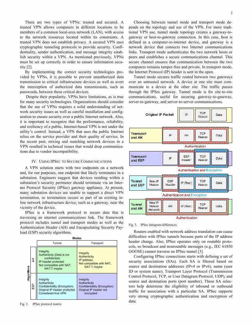
Choosing between tunnel mode and transport mode de-pends on the topology and use of the VPN. For more tradi-tional VPN use, tunnel mode topology creates a gateway-to-gateway or host-to-gateway connection. In this case, host is defined as a computer-to-internet device, and gateway is a network device that connects two Internet communications links. Transport mode authenticates the two network hosts or peers and establishes a secure communications channel. This secure channel ensures that communication between the two computers remains tamper-free and private. In transport mode, the Internet Protocol (IP) header is sent in the open.
Tunnel mode secures traffic routed between two gateways over an untrusted network. A device at one site must com-municate to a device at the other site. The traffic passes through the IPSec gateway. Tunnel mode is for site-to-site communications, useful for securing gateway-to-gateway, server-to-gateway, and server-to-server communications.
Fig. 3. IPSec datagram differences
Routers enabled with network address translation can cause difficulties with IPSec tunnels because parts of the IP address header change. Also, IPSec operates only on routable proto-cols, so broadcast and nonroutable messages (e.g., IEC 61850 GOOSE) cannot traverse an IPSec tunnel [3].
Configuring IPSec connections starts with defining a set of security associations (SAs). Each SA is filtered based on source and destination addresses (IPv4 or IPv6), name (user ID or system name), Transport Layer Protocol (Transmission Control Protocol, TCP, or User Datagram Protocol, UDP), and source and destination ports (port number). These SA selec-tors help determine the eligibility of inbound or outbound traffic for association with a particular SA. IPSec supports very strong cryptographic authentication and encryption of data.

3
Through the use of SA selectors, it is possible to write access control list entries that force a router to apply the IPSec protocol to very specific TCP/IP traffic profiles. Since IPSec functions at lower layers of the Open Systems Interconnection (OSI) model, there is open exposure to the TCP/UDP header. Therefore, it is possible to filter all network traffic into a set of SAs. This filter controls all traffic that enters or leaves the IPSec device, and no host between the endpoints of the IPSec tunnel can inject malicious packets or analyze the communi-cation. This makes the IPSec VPN operate like a rudimentary firewall, as discussed later in Section V.
Substation
Cyberassets(VLAN 1)
Critical Cyberassets (VLAN 2)
Protection(VLAN 3)
VLAN 1
VLAN 2
IPSec SA 1
IPSec SA 1
Metering
SCADA
Engineering Access
SCADA
Metering
IPSec SA 1, 2
Fig. 4. IPSec VPN operating with a VLAN and a firewall
During a cyberattack, IPSec VPN traffic traveling through a router is filtered so that any frames an attacker forms and attempts to send to a substation computer are dropped. The packets do not pass because the frames fail authentication and/or decryption. An encryption/authentication key must be used to code all data, and the network devices accept or deny this traffic.
IPSec issues arise due to the misconfiguration of the tunnel during setup, which introduces security holes. For example, implementing a traffic filter without any authentication verifi-cation on the packets could allow a knowledgeable attacker to send malicious TCP/IP traffic that matches the expected traffic profile. Thus, the rogue traffic survives filtering. A hacker is then able to pose as a legitimate device on the substation network, and malicious traffic can be sent to the substation device by faking or spoofing the IP address.
V. FIREWALLS AS A SECURITY MEASURE WITH IPSEC VPNS The last security tool discussed in this paper is the firewall.
The name and its function originate from the firewall that can be found in automobiles or applied in the construction of buildings. An automobile’s firewall confines fire to the engine compartment, preventing fire from progressing to the driver and passenger areas. The firewall must have holes in it for certain functions, such as steering, throttle control, and brak-
ing. Likewise, a network firewall restricts illegitimate traffic from flowing on the network segment but allows legitimate data to proceed. The firewall makes these decisions based on a set of rules. Another firewall feature is the ability to log or document actions, including auditing actions. The rules for a firewall originate from a well-defined security policy.
Typically, a firewall operates between network boundaries, where network communications meet. For example, a firewall would be found where data from the Internet (outsiders) meet the data from a corporate intranet (insiders).
Firewalls are often built into network equipment, such as computers, gateways, or routers, and provide a means to restrict network traffic, such as preventing outsiders from connecting to insiders. Just as there are holes in an automotive firewall, the rules for a substation may allow network holes, or ports, to allow certain TCP/IP network traffic to pass. For example, a firewall may have holes to pass email traffic assigned to Port 25 (Simple Mail Transfer Ptrotocol, SMTP) or Port 110 (Post Office Protocol 3, POP3). These ports in the firewall allow legitimate network traffic to pass but drop illegitimate traffic. Firewall rules that drop data packets often create an alarm or log file that notifies the user and/or administrator of a problem. As with any security tool, a firewall requires an understanding of the network design; unintentionally or inaccurately changing a firewall rule can impede important network traffic.
There are several firewall types: packet filtering, stateful inspection, and application proxy. Packet filtering examines the IP address and/or port and accepts or denies the packet through the firewall. The more popular type of firewall is called stateful inspection (often referred to as a session-based firewall), which bases the rules on the state of a connection or session. It adds slightly more depth to its protection. There are Unix-based firewalls that run off iptables or ipfilters. These work well for a substation environment because they allow for some degree of fine-tuning (e.g., allowing control system packets and rejecting all other traffic). Unix-based firewalls require more time and greater expertise to set up. As the name implies, an application proxy sets up an intermediary hardware path for the data packets. The proxy hardware receives all traffic to and from the destination and filters traffic based on its rule set. One advantage of a proxy firewall is that it hides the true IP addresses from outsider connections.
Firewalls log and document attempts to connect to the network. These log files are an important source of useful information that can be used to prevent illegitimate access to a substation environment.
VI. CREATING AN IPSEC VPN The appendix of this paper explains how to set up and
encrypt the connections between two computers using the Windows® XP operating system with built-in IPSec capabili-ties. The example provides step-by-step instructions to con-figure an IPSec VPN between two computers. This example works between two laptops connected via a crossover cable or network hub. In general, the following steps must occur on

4
both computers in order to establish a cryptographically secure communications channel:
• Create a new IPSec policy. • Create rules within the policy. • Define how to filter (identify) the traffic to encrypt. • Select the filters to use. • Activate the policy. • Connect to computers using a remote desktop
connection. To begin the process of creating a secure connection
between the computers, create a local security policy in both computers. After the IPSec VPN is configured on both com-puters, verify that only these IPSec-enabled computers can communicate with each other.
When the two computers are connected via a network hub (a network switch will not work in this case), a third computer with a software packet sniffer, such as Wireshark®, allows the user to view the data packets and encrypted data.
Fig. 5. Creating an example IPSec VPN
VII. CONCLUSION This paper describes several cybersecurity tools to help
protect and control data that may need to traverse untrusted network paths located near substation networks. The substa-tion automation professional should be aware of security measures, such as firewalls and VPN IPSec tunnels, that allow for improved secure remote access. Using firewalls and IPSec VPNs helps protect networks from malicious traffic, while VLANs help to provide resiliency.
5
VIII. APPENDIX The following procedures will need to occur on both computers.
A. Configure Windows XP to Accept Remote Desktop Connections
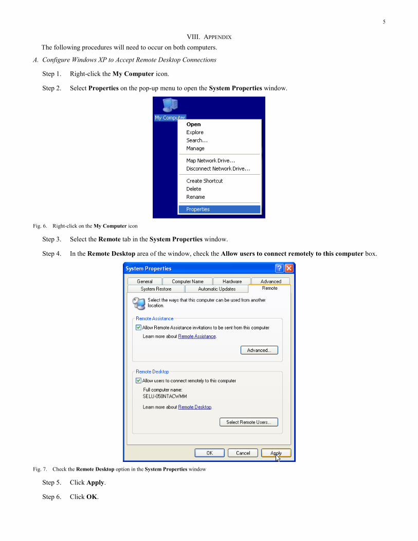
Step 1. Right-click the My Computer icon.
Step 2. Select Properties on the pop-up menu to open the System Properties window.
Fig. 6. Right-click on the My Computer icon
Step 3. Select the Remote tab in the System Properties window.
Step 4. In the Remote Desktop area of the window, check the Allow users to connect remotely to this computer box.
Fig. 7. Check the Remote Desktop option in the System Properties window
Step 5. Click Apply.
Step 6. Click OK.

6
B. Create New User Account
Step 1. Navigate to Start > Settings > Control Panel, and choose User Accounts. The User Accounts window will open.
Step 2. Click on Create a new account.
Fig. 8. Select Create a new account in the User Accounts window
Step 3. Type RDP for the new account name in the area provided. Click Next.
Fig. 9. Name the new account

7
Step 4. Select Computer administrator as the account type. Click the Create Account button.
Fig. 10. Select Computer administrator
Step 5. Select the RDP user account that was just created.
Step 6. Select Create a password.
Fig. 11. Click on Create a password
8
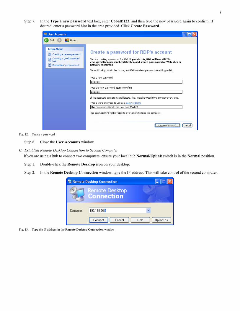
Step 7. In the Type a new password text box, enter Cobalt!123, and then type the new password again to confirm. If desired, enter a password hint in the area provided. Click Create Password.
Fig. 12. Create a password
Step 8. Close the User Accounts window.
C. Establish Remote Desktop Connection to Second Computer If you are using a hub to connect two computers, ensure your local hub Normal/Uplink switch is in the Normal position.
Step 1. Double-click the Remote Desktop icon on your desktop.
Step 2. In the Remote Desktop Connection window, type the IP address. This will take control of the second computer.
Fig. 13. Type the IP address in the Remote Desktop Connection window

9
Step 3. Log in to the second computer using the RDP account that was previously created.
Fig. 14. Log in to second computer
Step 4. Log in to the second computer by clicking Yes in the Logon Message window. The first computer is now logged out, and you are operating the second computer.
Fig. 15. Click Yes in the Logon Message window
Step 5. Select Log Off RDP on the Start menu.
Step 6. Click Log Off in the Log Off window.
Step 7. On the second computer, repeat Step 1 through Step 6.
D. Create a Remote Desktop Security Policy
Step 1. Select Local Security Policy from Start > Settings > Control Panel > Administrative Tools. The Local Security Settings window will open.
Fig. 16. Local Security Settings window
Step 2. Click the Create an IP Security policy icon in the Local Security Settings window.
Fig. 17. Click on the IP Security policy icon

10
Step 3. Click Next.
Fig. 18. IP Security Policy Wizard window
Step 4. Type a name for this security policy in the area provided. If desired, type a description for the policy. Click Next.
Fig. 19. Assign IP Security Policy Name

11
Step 5. Remove the check mark from the Activate the default response rule box. Click Next.
Fig. 20. Remove check mark from Activate the default response rule
Step 6. Check the box next to Edit properties, and click Finish. The Secure Remote Desktop Properties window will open.
Fig. 21. Check Edit properties

12
Step 7. Check the Use Add Wizard box, and click the Add button. The Security Rule Wizard window will open.
Fig. 22. Rules tab in Security Remote Desktop Properties window
Step 8. Click Next.
Fig. 23. Start Security Rule Wizard

13
Step 9. Select the This rule does not specify a tunnel radio button. Click Next.
Note: If setting up a secure connection between two computers on a server, select a tunnel, and define the appropriate IP addresses. This also implies that the network interface card (NIC) on both computers would need to use static IP addresses in the network configuration menu. For example, if the NIC card on Computer A is 198.162.1.1, and it is 198.162.1.2 on Computer B, then the tunnel IP address for Computer A is 198.162.1.2, and the tunnel IP address for Computer B is 192.162.1.1.
Fig. 24. Specify tunnel endpoint rule
Step 10. Select the All network connections radio button. Click Next.
Fig. 25. Select network type

14
Step 11. Select the Use this string to protect the key exchange (preshared key) radio button.
Step 12. Type mykeyA10_! in the text box provided. Click Next.
Note: If the encryption keys do not match, the IPSec connection will fail. This results in an authentication failure between the two computers.
Fig. 26. Authentication Method window
Step 13. Ensure that no radio buttons are selected, and then click the Add button.
Fig. 27. IP Filter List window

15
Step 14. Enter the IP filter Name and Description in the text boxes. Check the Use Add Wizard box, and then click Add.
Fig. 28. Name IP Filter
Step 15. Click Next.
Fig. 29. IP Filter Wizard window

16
Step 16. Identify the attributes of the IP traffic that you want to act on with an IP filter. In the Source address drop-down list, select Any IP Address. Click Next.
Fig. 30. Select IP Traffic Source
Step 17. Continue to define the attributes of the IP traffic that you want to act on as the filter is built. In the Destination address drop-down list, select My IP Address. Click Next.
Fig. 31. Select IP Traffic Destination

17
Step 18. In the Select a protocol type drop-down list, select TCP. Click Next.
Fig. 32. Select IP Protocol Type
Step 19. Select the From any port and To any port radio buttons. Click Next.
Fig. 33. Select IP Protocol Port

18
Step 20. Ensure that Edit properties is unchecked. Click Finish.
Fig. 34. Completion screen
Step 21. Click OK.
Fig. 35. IP Filter List window

19
Step 22. Select the radio button for the new IP filter in the IP Filter List. Click Next.
Fig. 36. Select appropriate radio button
Step 23. Select the Require Security radio button. Click Next.
Note: The Require Security action insists that all communications be encrypted, while Request Security is more lenient and would allow connections to hosts that do not support your encryption requirements.
Fig. 37. Filter Action screen

20
Step 24. Ensure that Edit properties is unchecked. Click Finish.
Fig. 38. Completion screen
Step 25. Check the Remote Desktop box. Click Close.
Fig. 39. Rules tab of Secure Remote Desktop Properties window
21
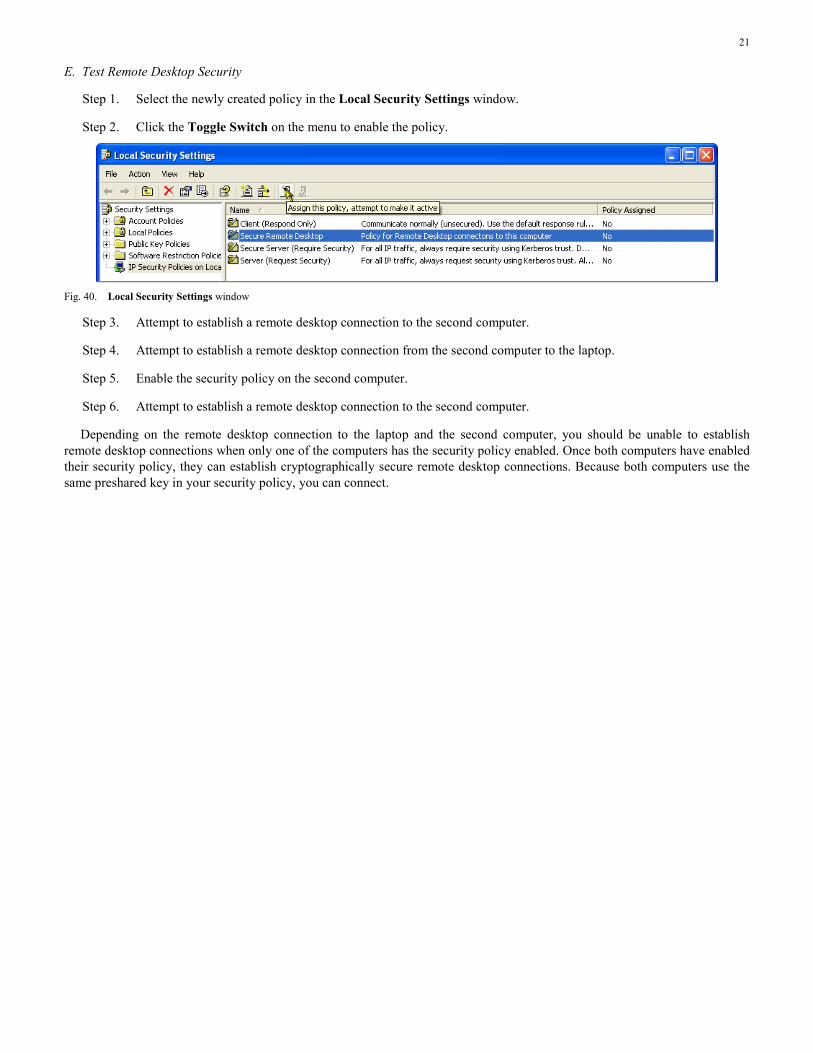
E. Test Remote Desktop Security
Step 1. Select the newly created policy in the Local Security Settings window.
Step 2. Click the Toggle Switch on the menu to enable the policy.
Fig. 40. Local Security Settings window
Step 3. Attempt to establish a remote desktop connection to the second computer.
Step 4. Attempt to establish a remote desktop connection from the second computer to the laptop.
Step 5. Enable the security policy on the second computer.
Step 6. Attempt to establish a remote desktop connection to the second computer.
Depending on the remote desktop connection to the laptop and the second computer, you should be unable to establish remote desktop connections when only one of the computers has the security policy enabled. Once both computers have enabled their security policy, they can establish cryptographically secure remote desktop connections. Because both computers use the same preshared key in your security policy, you can connect.

22
IX. REFERENCES [1] P. Oman, E. O. Schweitzer, III, and D. Frincke, “Concerns About
Intrusions Into Remotely Accessible Substation Controllers and SCADA Systems,” proceedings of the 55th Annual Georgia Tech Protective Relaying Conference, Atlanta, GA, 2001.
[2] P. Oman, A. Risley, J. Roberts, and E. O. Schweitzer, III, “Attack and Defend Tools for Remotely Accessible Control and Protection Equipment in Electric Power Systems,” proceedings of the 56th Annual Georgia Tech Protective Relaying Conference, Atlanta, GA, 2002.
[3] IEEE Guide for Electric Power Substation Physical and Electronic Security, IEEE Standard 1402-2000, April 2000.
X. BIOGRAPHY Dwight Anderson received his BS in electrical engineering from Steven’s Institute of Technology. He is now the security product manager for Schweitzer Engineering Laboratories, Inc. (SEL) in Pullman, Washington. Prior to joining SEL in 2005, he worked 20 years for Hewlett-Packard as an aerospace and defense business development manager and systems engineer, working on projects ranging from electronic warfare countermeasures to SCADA system programming. He recently became a member of the FBI InfraGard forum, regarding the exchange of information related to critical infrastructure protection. He holds the Global Security Essentials Certification (GSEC) from Global Information Assurance Certification (GIAC) and is a Certified Information Systems Security Professional (CISSP).
© 2009 by Schweitzer Engineering Laboratories, Inc. All rights reserved.
20090206 • TP6365-01