Securing Embedded Systems for Autonomous Aerial … · Securing Embedded Systems for Autonomous...
182
Project Number: AW1- 12ES Securing Embedded Systems for Autonomous Aerial Vehicles A Major Qualifying Project Report Submitted to the faculty of WORCESTER POLYTECHNIC INSTITUTE in partial fulfillment of the requirements for the degree of Bachelor of Science Submitted by: Phuoc Luong Electrical and Computer Engineering _______________________________________________________ Roni Rostom Electrical and Computer Engineering _______________________________________________________ Evan Ziavras Electrical and Computer Engineering _______________________________________________________ Advisors: Professor Alexander Wyglinski Electrical and Computer Engineering _______________________________________________________ Professor Thomas Eisenbarth Electrical and Computer Engineering _______________________________________________________ On April 24, 2013
Transcript of Securing Embedded Systems for Autonomous Aerial … · Securing Embedded Systems for Autonomous...
Project Number: AW1- 12ES
Securing Embedded Systems
for Autonomous Aerial Vehicles
A Major Qualifying Project Report
Submitted to the faculty of WORCESTER POLYTECHNIC INSTITUTE
in partial fulfillment of the requirements for the degree of Bachelor of Science
Submitted by:
Phuoc Luong Electrical and Computer Engineering
_______________________________________________________
Roni Rostom Electrical and Computer Engineering
_______________________________________________________
Evan Ziavras Electrical and Computer Engineering
_______________________________________________________
Advisors:
Professor Alexander Wyglinski Electrical and Computer Engineering
_______________________________________________________
Professor Thomas Eisenbarth Electrical and Computer Engineering
_______________________________________________________
On
April 24, 2013
Abstract
This project focuses on securing embedded systems for unmanned aerial vehicles (UAV).
Over the past two decades UAVs have evolved from a primarily military tool into one that is
used in many commercial and civil applications. Today they are used in military strikes, weather
monitoring, search and rescue missions, and many other fields. As the market for these products
increases the need to protect transmitted data becomes more important. UAVs are flying
missions that contain crucial data and without the right protection they can be vulnerable to
malicious attacks. This project focuses on building a UAV platform and working to protect the
data transmitted on it. Areas that were focused on for security included the image processing
and wireless communications modules. Vulnerabilities were found in these areas and ways were
found in which they could be improved. This report contains knowledge concerning how UAVs
are currently used, prior arts, computing options, implementation of building a prototype and
attacks, and results and discussion of this work.
Contents
1. Introduction ........................................................................................................................................ 1
1.1. UAV Market Analysis ..................................................................................................................... 2
1.2. Importance of UAVs ...................................................................................................................... 5
1.3. Benefits of UAVs ........................................................................................................................... 7
1.3.1. Civilian Uses ........................................................................................................................... 9
1.3.2. National Defense Uses ......................................................................................................... 12
1.4. Importance of Security of UAV Systems ...................................................................................... 14
1.5. Proposed Approach .................................................................................................................... 16
1.6. Report Organization .................................................................................................................... 19
2. Overview of UAV Systems .................................................................................................................. 21
2.1. History of UAVs ........................................................................................................................... 21
2.2. Current UAV Applications............................................................................................................ 24
2.3. Design Considerations ................................................................................................................. 35
2.4. Computing Architecture of UAVs................................................................................................. 38
2.5. Prior Art of Previous UAV Projects............................................................................................... 40
2.6.1. Worcester Polytechnic Institute ........................................................................................... 41
2.6.2. Massachusetts Institute of Technology ................................................................................. 44
2.6.3. Brigham Young University .................................................................................................... 46
2.6.4. University of Linkoping ......................................................................................................... 48
2.6. Current Security of Unmanned Aerial Vehicle Technology ........................................................... 50
2.7. Chapter Summary ....................................................................................................................... 52
3. Proposed Approach ........................................................................................................................... 54
3.1. Computing Options ..................................................................................................................... 54
3.1.1. Design Architectures ............................................................................................................ 54
3.1.2. Processor Options ................................................................................................................ 59
3.1.3. Processing Tasks................................................................................................................... 69
3.2. Framework Architecture ............................................................................................................. 72
3.3. Value Analysis ............................................................................................................................. 74
3.3.1. Power .................................................................................................................................. 74
3.3.2. Autopilot .............................................................................................................................. 76
3.2.3. Image Processing Module .................................................................................................... 83
3.2.4. Communication .................................................................................................................... 84
3.2.5. Camera ................................................................................................................................ 89
3.4. Security....................................................................................................................................... 93
3.5. Tasks Division.............................................................................................................................. 95
3.4. Chapter Summary ....................................................................................................................... 95
4. Design Methodology and Implementation ......................................................................................... 97
4.1. Autopilot .................................................................................................................................... 98
4.2. Communication ........................................................................................................................ 100
4.2.2. Socket Programming Codes ................................................................................................ 106
4.2.3. Use of Virtual Machine ....................................................................................................... 107
4.3. Image Processing ...................................................................................................................... 110
4.4. Attacks ...................................................................................................................................... 116
4.4.1. Red Color Attack ................................................................................................................ 116
4.4.2. Wireless Attacks ................................................................................................................. 119
4.5. Integrated Prototype Implementation ...................................................................................... 124
4.6. Chapter Summary ..................................................................................................................... 125
5. Results and Discussion ..................................................................................................................... 127
5.1. Platform Functionality............................................................................................................... 127
5.1.1. Image Processing Functionality .......................................................................................... 127
5.1.2. Socket Programming Functionality ..................................................................................... 128
5.1.3. File Sharing Functionality ................................................................................................... 129
5.1.4. Autopilot Functionality ....................................................................................................... 130
5.2. Attack Results ........................................................................................................................... 134
5.2.1. Color Attacks ...................................................................................................................... 135
5.2.2. Wireless Attacks ................................................................................................................. 140
5.3. Indoor Testing ........................................................................................................................... 147
5.4. Chapter Summary ..................................................................................................................... 149
6. Conclusions and Future Recommendations...................................................................................... 150
6.1. Conclusions ............................................................................................................................... 150
6.2. Future Work ............................................................................................................................. 152
Appendix A .......................................................................................................................................... 154
Appendix B .......................................................................................................................................... 156
Appendix C .......................................................................................................................................... 158
Bibliography ........................................................................................................................................ 163
List of Figures
Figure 1 - National Defense use of a UAV: a predator drone takes off on a U.S. customs border
Protection mission [3]. ............................................................................................................................ 2
Figure 2 - This image shows a search and rescue mission. The dotted circle shows where a dummy was
dropped off in the Utah wilderness. Researchers are working on object-detection algorithms that would
allow the UAV to find the missing person [1]. .......................................................................................... 2
Figure 3 - The UAV funding witnessed a major increase since 2009. A 35% funding increase in the UAVs
market was carried out since 2009 [6]. .................................................................................................... 3
Figure 4 - Expected revenue for the different UAV types [4]. ................................................................... 4
Figure 5 - Pteryx UAV for aerial photography is an example of a UAV civilian application [8]. ................... 5
Figure 6 - UAV with thermal Infrared camera to locate people by identifying body heat [11]. .................. 6
Figure 7 - Kettering Bug. This is the first UAV that was employed by American national security forces,
making a big benchmark in the history of UAVs [13]. ............................................................................... 7
Figure 8 - German FI 103 V1. This plane was used by the Germans during World War II to launch air
attacks at London [15]. ............................................................................................................................ 8
Figure 9 - Pioneer drone [18]. .................................................................................................................. 9
Figure 10 - Predator drone. This and the Pioneer (Figure 7) are two prominent UAVs used by United
States defense forces in the recent wars in Iraq and Afghanistan. They have provided invaluable help as
they can carry out missions with a dramatically decreased risk for loss of life [19]. .................................. 9
Figure 11 - Aerosonde UAV is being released from its transport vehicle to fly into Tropical Storm Ophelia
in 2005. Its mission is to gather weather information for better understanding of tropical storm [21]. .. 10
Figure 12 - MLB Bat is prepared to be launched at Moffett Field. The UAVs is launched in flocks like bird
and they would gather information for possible risk of wildfire [22]. ..................................................... 11
Figure 13 - Video feed of U.S. Army UAVs. This video was used to spy on OPFOR mounted elements,
which is a group designated to simulate the enemy in preparation for battle. This screenshot proves how
defense teams can use video from UAVs to watch enemy movement [26]. ........................................... 13
Figure 14 - Reaper drone [27]. ............................................................................................................... 14
Figure 15 - UAV Proposed Design. All components are shown as well as data and connection types. The
central computing unit (CCU) handles the main plane operations and is fed data from the autopilot and
camera modules. This is then sent to the base station via Wi-Fi. ............................................................ 17
Figure 16 - The final design prototype.................................................................................................... 18
Figure 17 - Leonardo Da Vinci’s flying machine [34]. .............................................................................. 22
Figure 18 - Aerial Steam Carriage by John Stringfellow and William Henson in 1848. The plane can fly for
a distance without any human interaction. However, it still lacks autonomous feature [33]. ................. 22
Figure 19 - Kettering Bug by Charles Kettering and Dayton Wright Airplane Company in 1918. The plane
has simple autonomous system designed for finding and destroying enemy aircraft [35]. ..................... 23
Figure 20 - Tactical UAV is used to support the brigade with integral intelligence, reconnaissance and
target acquisition at distances of up to 200 km [36]. .............................................................................. 25
Figure 21 - The UAV command center of a Reaper drone. The pilot is sitting to the left and the sensor
operator is sitting on the right. Although the pilot needs to command the plane with the same sense of
caution as he would a regular manned aircraft, he is removed from all danger [37]. .............................. 26
Figure 22 - The largest UAV in the USAF to date, this aircraft can stay in the air for two full days [38]. ... 27
Figure 23 - Outline of a typical United States drone mission in Afghanistan. The UAV is normally
deployed to the location of an enemy combatant and circles the area waiting for positive identification
of the target and clearance. Drones are not allowed to strike if there are women and children nearby,
making strikes on residential dwellings forbidden. The drones return to base once a positive strike is
confirmed. ............................................................................................................................................. 28
Figure 24 - Interactive map revealing where UAVs are being flown inside the USA [40]. ........................ 29
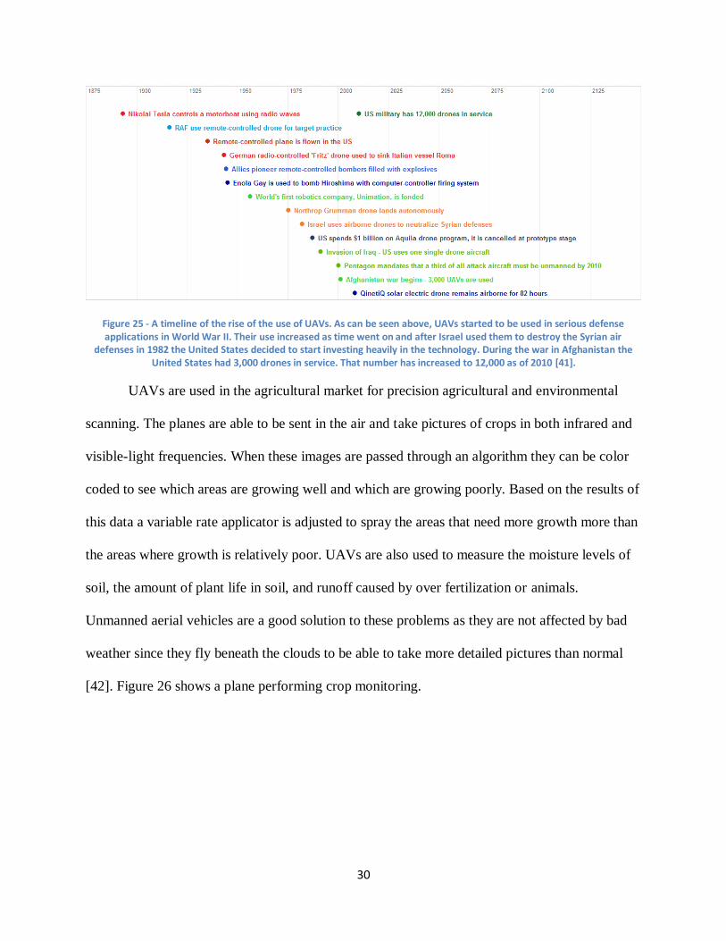
Figure 25 - A timeline of the rise of the use of UAVs. As can be seen above, UAVs started to be used in
serious defense applications in World War II. Their use increased as time went on and after Israel used
them to destroy the Syrian air defenses in 1982 the United States decided to start investing heavily in
the technology. During the war in Afghanistan the United States had 3,000 drones in service. That
number has increased to 12,000 as of 2010 [41]. ................................................................................... 30
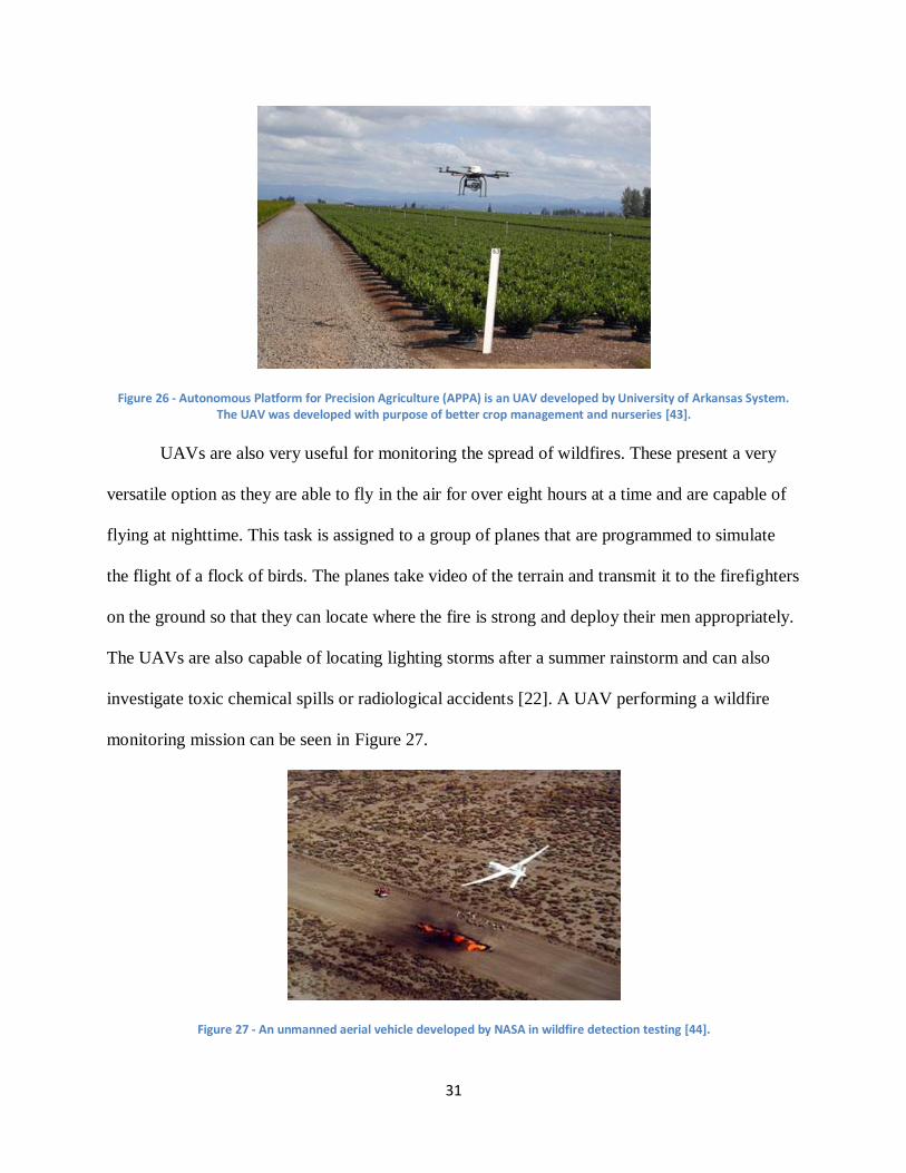
Figure 26 - Autonomous Platform for Precision Agriculture (APPA) is an UAV developed by University of
Arkansas System. The UAV was developed with purpose of better crop management and nurseries [43].
.............................................................................................................................................................. 31
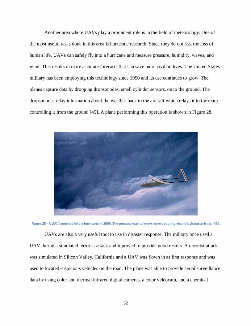
Figure 27 - An unmanned aerial vehicle developed by NASA in wildfire detection testing [44]. .............. 31
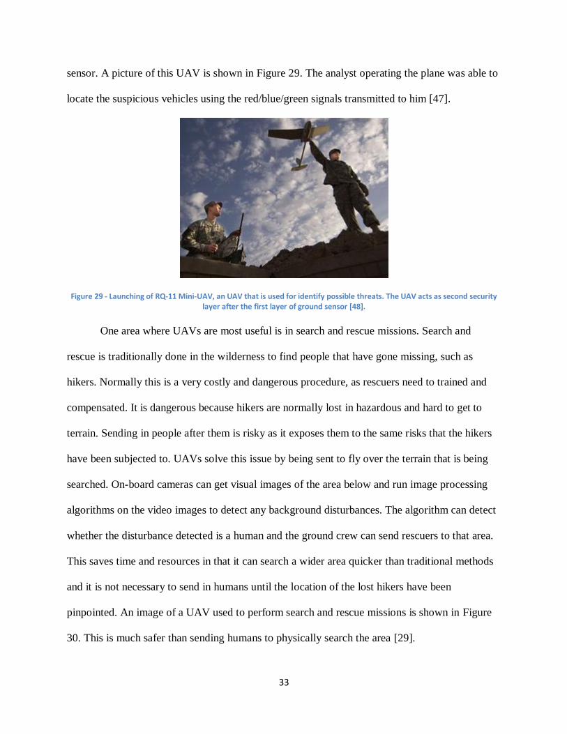
Figure 28 - A UAV launched into a hurricane in 2008. The purpose was to know more about hurricane’s
characteristics [46]. ............................................................................................................................... 32
Figure 29 - Launching of RQ-11 Mini-UAV, an UAV that is used for identify possible threats. The UAV acts
as second security layer after the first layer of ground sensor [48]......................................................... 33
Figure 30 - A search and rescue UAV that is used for finding missing people. The UAV was developed by
Flat Eight Productions, Inc. [49]. ............................................................................................................ 34
Figure 31 - A UAV is being tested in traffic controlling in UK. It can also be used to track down car chases,
hidden suspects and monitor riots or protests [51]. ............................................................................... 35
Figure 32 - Comparison of UAV specifications. The x-axis represents the planes’ wingspans, the y-axis
represents their payload capacity, and the z-axis represents their power requirements. ....................... 37
Figure 33 - MQ-1 Predator [54]. ............................................................................................................. 38
Figure 34 - General UAV architecture consists of camera, image processing, autopilot, CCU,
communication and a base station. ....................................................................................................... 40
Figure 35 - WiND project architecture consists of camera, image processing, autopilot, path planning,
communication and base station modules. Data is computed inside the UAV [55]................................. 43
Figure 36 - System architecture of RAVEN project from MIT. The data processing tasks are not computed
in the UAV but on a ground station [30]. ............................................................................................... 45
Figure 37 - Magicc UAV System Architecture [31]. ................................................................................. 48
Figure 38 - Witas UAV Network Architecture uses Ethernet switch to communicate between modules
[32]. ...................................................................................................................................................... 49
Figure 39 - Model of typical a sensor network. Data is transferred to the outside world using different
types of sensors..................................................................................................................................... 51
Figure 40 - First design option. All modules are separate. This provides more flexibility but weights more,
takes up more room, and costs more. ................................................................................................... 56
Figure 41 - Second design option. This combines image processing, the CCU, and the encryption module
on one processor. While this saves money and weighs less, memory capacity is a concern and it might be
harder to implement image processing. ................................................................................................ 57
Figure 42 - Third design option. This offers the advantage of allowing the encrypting to be done by the
CCU’s specific encryption module. This also saves weight and money while allowing a separate model
that is more suited for image processing to be picked out for it. ............................................................ 58
Figure 43 - OMAP 4470 architecture. This shows all of the processors inside the OMAP as well as the
wireless, audio, and other connectivity ports [59].................................................................................. 61
Figure 44 - MSP430 microprocessor architecture. This shows all of the memory, the ADC, DAC,
input/output ports, and clocks [63]. ...................................................................................................... 64
Figure 45 - A typical digital signal processing system. ............................................................................. 66
Figure 46 - Spartan 6 architecture with data links [64]. .......................................................................... 67
Figure 47 - Lena. This is the image that algorithms normally use to test their effectiveness against [68]. 71
Figure 48 - Project detailed system architecture that has data links between modules. The platform has
CCU and Encryption module being implemented in one board for saving resources. ............................. 74
Figure 49 - Paparazzi communication. This shows how the autopilot module interacts with the ground
station and the user interface [69]. ........................................................................................................ 78
Figure 50 - Kestrel autopilot [72]. .......................................................................................................... 79
Figure 51 - Piccolo SL autopilot [74]. ...................................................................................................... 80
Figure 52 - OpenPilot autopilot [76]. ...................................................................................................... 80
Figure 53 - Type M Wi-Fi bullet [77]. ...................................................................................................... 85
Figure 54 - Zigbee, a module of Xbee products [78]. .............................................................................. 86
Figure 55 - A Bluetooth dongle for wireless communication [79]. .......................................................... 87
Figure 56 - Sony FCBIX45C camera [80]. ................................................................................................. 90
Figure 57 - Black Widow KX131 Color CCD camera [81]. ......................................................................... 90
Figure 58 - Draganfly SAVS platform [82]. .............................................................................................. 91
Figure 59 - FCB-EX470LP camera [83]..................................................................................................... 91
Figure 60 - System architecture of a sensor network model. The camera is the data receiving sensor,
ArduPilot and Wi-Fi bullet is bi-directional sensor. ................................................................................. 93
Figure 61 - Encryption process alters original data (plaintext) into another form (cipher text). Decryption
is the opposite process. ......................................................................................................................... 94
Figure 62 - The PoE adapter is powering the bullet and linking the Beagleboard to the bullet via Ethernet
cords. .................................................................................................................................................. 101
Figure 63 - AirOS wireless configuration page. ..................................................................................... 103
Figure 64 - AirOS network configuration page. ..................................................................................... 104
Figure 65 - Connecting the bullets together using AirControl. .............................................................. 104
Figure 66 - Socket programming testing. The base station received the message sent by the Beagleboard.
............................................................................................................................................................ 106
Figure 67 - RGB convention states that all colors are composed of a certain degree of red, green and
blue. White color means equal maximum amount of both three and black means none of three [90]. 114
Figure 68 - HSV convention’s color is decided mainly based on hue value. Saturation decides strength of
the color and value decides its brightness [90]. ................................................................................... 115
Figure 69 - Color filter process: First image was the original image, second image was converted to HSV
color plane and last one was filtering out non-red pixels. .................................................................... 115
Figure 70 - The testing module: camera and light source was placed in front of a white wall facing each
other, light source and camera had a distance of d and shining angle of a. .......................................... 117
Figure 71 - The LED flashlight that was used had three LEDs with different colors: red, blue and green.
The LED had a solid lighting mode as well as a flashing mode. ............................................................. 118
Figure 72 - The laser light that was used was a level measurement laser. Its light could reach more than 5
feet distance [91]. ............................................................................................................................... 119
Figure 73 - The Aircrack-ng code used to send deauthentication packets to the bullets. These packets
contained random, meaningless bits that should not allow the two bullets to connect with one another.
............................................................................................................................................................ 121
Figure 74 - Box architecture. ................................................................................................................ 125
Figure 75 - The latitude, longitude, and altitude was sent to the base station after the red color was
detected. The first line in the above picture represents the client code command. This command must
be run in order to communicate with the server. The Beagleboard keeps on sending the GPS information
as long as the red color is still being detected. ..................................................................................... 129
Figure 76 - The flight simulation as it appears on the ground control software. This operates in real time
and tracks the plane’s orientation and altitude. ................................................................................... 131
Figure 77 - Data window on the Mission Planner software. All important data is shown such as roll, pitch,
yaw, latitude, and longitude. ............................................................................................................... 132
Figure 78 - Location of the autopilot. The software uses Google Maps to produce an interactive map
showing the location of the board and the direction in which it is facing. The current location is at
Atwater-Kent Laboratories at Worcester Polytechnic Institute in Worcester, MA. ............................... 133
Figure 79 - Red LED image after the algorithm was applied to it. Although it was detected as a positive
result, the LED could only be effective for short distances. .................................................................. 136
Figure 80 - Laser image after processed by the algorithm. Laser light was proven to be very effective as
an attacking light source with greater distance and shining angles. ..................................................... 138
Figure 81 - Laser light after the saturation filter is applied to it. The area of detected pixels had been
reduced greatly, making laser light no longer a threat to the algorithm. .............................................. 139
Figure 82 - The Wi-Fi bullets captured packets ..................................................................................... 141
Figure 83 - Packets transfer between the Beagleboard and the Base Station ....................................... 142
Figure 84 - The hallway where indoor testing was performed. The platform can be seen in the lower left
corner. ................................................................................................................................................ 147
Figure 85 - A map of the WPI Sports and Recreation Center where indoor testing was performed. The
exact location of the testing was in the hallway connecting the Sports and Recreation Center to
Harrington Auditorium [95]. ................................................................................................................ 148
Figure 86 - The GPS information of the Beagleboard was sent to the base station placed at the end of the
hallway. This signifies that the platform performs as expected. ........................................................... 149
List of Tables
Table 1 - Comparison of plane specifications ......................................................................................... 37
Table 2 - Power requirement for project WiND system [55]. .................................................................. 41
Table 3 - Architecture comparison. ranking the three choises in seven different categories. As can be
seen, the third option was chosen for implementation in this project. ................................................... 59
Table 4 - Comparison table for the different kinds of microporcessors ................................................... 68
Table 5 - System power requirements ................................................................................................... 75
Table 6 - Batteries considerations summary .......................................................................................... 76
Table 7 - Autopilot comparison .............................................................................................................. 82
Table 8 - Image processing options summary......................................................................................... 84
Table 9 - Comparison of the Bluetooth, Zigbee, and the Wi-Fi protocols [66]. ........................................ 89
Table 10 - Camera options summary. ..................................................................................................... 93
Table 11 - Testing results for colored light attacks. The tests were conducted with different angles and
distances. ............................................................................................................................................ 135
1
1. Introduction
Countries around the globe have become increasingly reliant on unmanned aerial vehicles
(UAVs). UAVs are extremely useful in many areas such as the military, civilian, and commercial
fields and are a common tool to conduct search and rescue missions. These drones perform
missions with high levels of complexity and are useful for cases where a human pilot would face
certain risks. They require less human operator participation due to their autonomous behavior.
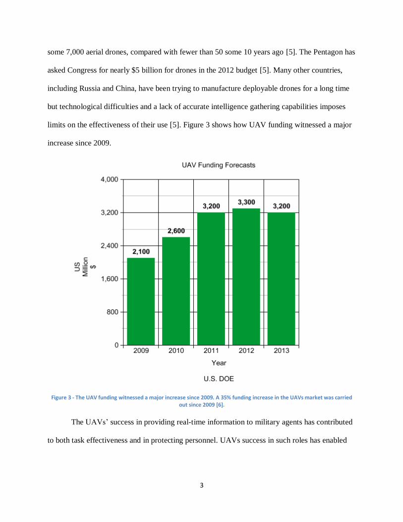
In the case of emergency situations such as natural disasters, UAV systems can be programmed
to complete missions from takeoff to landing. An example of this is shown in Figure 2 where a
UAV is used to find missing hikers in a search and rescue mission. These missions include high
navigation precision and long operation times that are tedious for human pilots. UAVs are also
much cheaper, faster, and safer than using helicopters for search and rescue mission according to
researchers [1]. Historically these drones were primarily used in defense operations but lately
they have seen more use in the civilian world. UAVs wide ranges of missions are also used by
the Air Force United States Marine Corps, Army, and Navy [2]. The National Defense UAVs
represent a variety of missions and technology that range from large vehicles that carry offensive
weapons to miniature systems whose components are light and compact to be carried in a
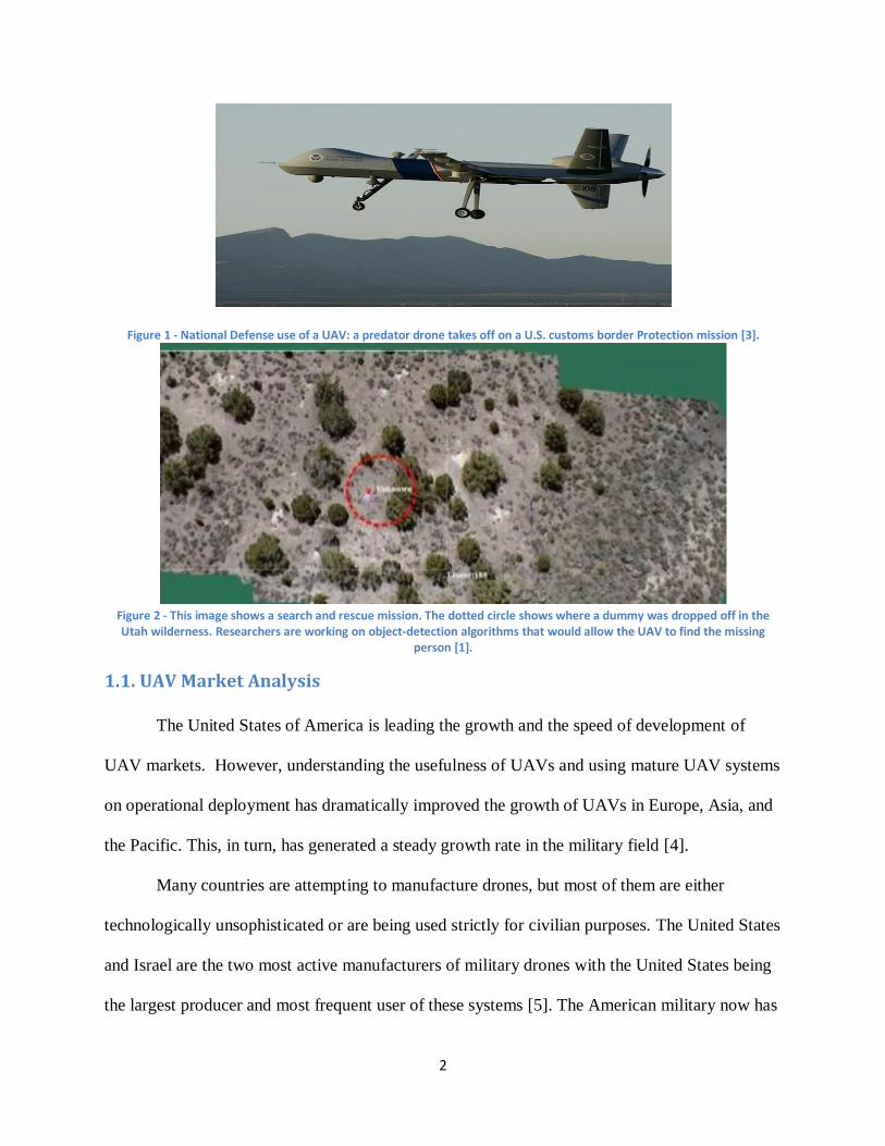
backpack. Figure 1 below shows a Predator drone, one of the most common UAVs used in
defense applications.
2
Figure 1 - National Defense use of a UAV: a predator drone takes off on a U.S. customs border Protection mission [3].
Figure 2 - This image shows a search and rescue mission. The dotted circle shows where a dummy was dropped off in the Utah wilderness. Researchers are working on object-detection algorithms that would allow the UAV to find the missing
person [1].
1.1. UAV Market Analysis
The United States of America is leading the growth and the speed of development of
UAV markets. However, understanding the usefulness of UAVs and using mature UAV systems
on operational deployment has dramatically improved the growth of UAVs in Europe, Asia, and
the Pacific. This, in turn, has generated a steady growth rate in the military field [4].
Many countries are attempting to manufacture drones, but most of them are either
technologically unsophisticated or are being used strictly for civilian purposes. The United States
and Israel are the two most active manufacturers of military drones with the United States being
the largest producer and most frequent user of these systems [5]. The American military now has
3
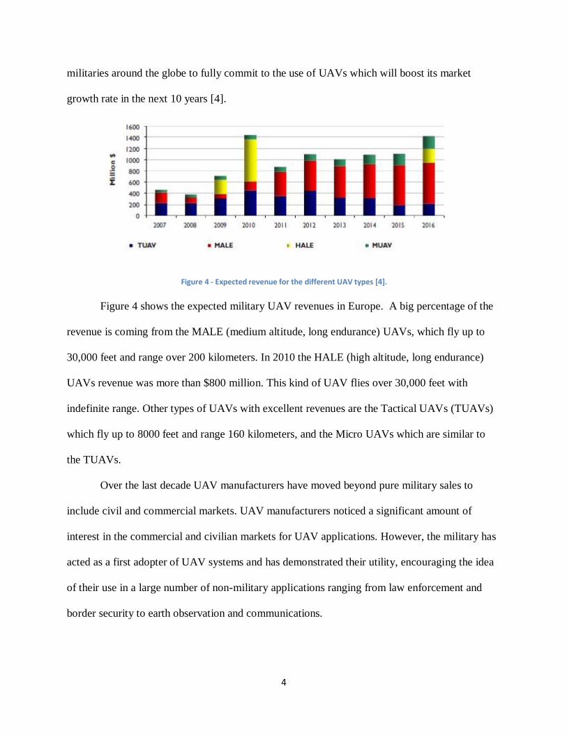
some 7,000 aerial drones, compared with fewer than 50 some 10 years ago [5]. The Pentagon has
asked Congress for nearly $5 billion for drones in the 2012 budget [5]. Many other countries,
including Russia and China, have been trying to manufacture deployable drones for a long time
but technological difficulties and a lack of accurate intelligence gathering capabilities imposes
limits on the effectiveness of their use [5]. Figure 3 shows how UAV funding witnessed a major
increase since 2009.
Figure 3 - The UAV funding witnessed a major increase since 2009. A 35% funding increase in the UAVs market was carried out since 2009 [6].
The UAVs’ success in providing real-time information to military agents has contributed
to both task effectiveness and in protecting personnel. UAVs success in such roles has enabled
4
militaries around the globe to fully commit to the use of UAVs which will boost its market
growth rate in the next 10 years [4].
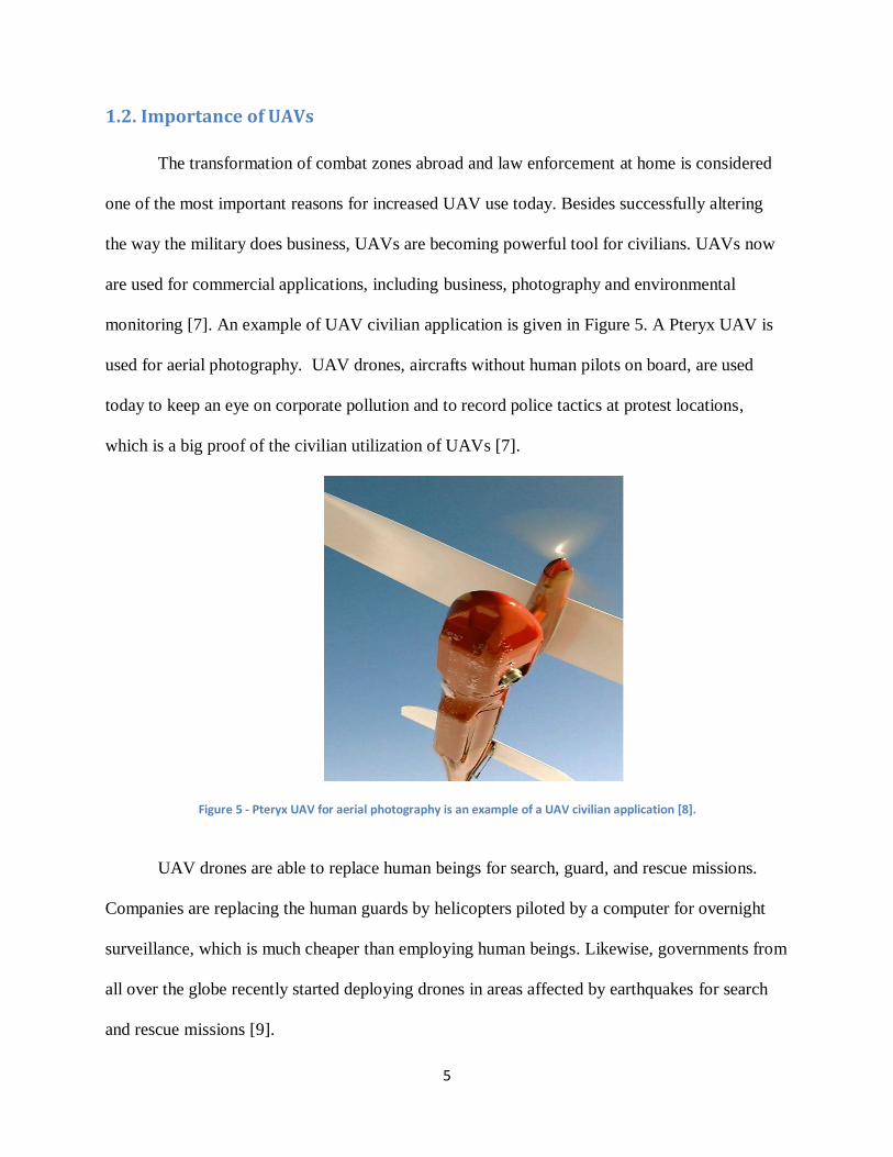
Figure 4 - Expected revenue for the different UAV types [4].
Figure 4 shows the expected military UAV revenues in Europe. A big percentage of the
revenue is coming from the MALE (medium altitude, long endurance) UAVs, which fly up to
30,000 feet and range over 200 kilometers. In 2010 the HALE (high altitude, long endurance)
UAVs revenue was more than $800 million. This kind of UAV flies over 30,000 feet with
indefinite range. Other types of UAVs with excellent revenues are the Tactical UAVs (TUAVs)
which fly up to 8000 feet and range 160 kilometers, and the Micro UAVs which are similar to
the TUAVs.
Over the last decade UAV manufacturers have moved beyond pure military sales to
include civil and commercial markets. UAV manufacturers noticed a significant amount of
interest in the commercial and civilian markets for UAV applications. However, the military has
acted as a first adopter of UAV systems and has demonstrated their utility, encouraging the idea
of their use in a large number of non-military applications ranging from law enforcement and
border security to earth observation and communications.
5
1.2. Importance of UAVs
The transformation of combat zones abroad and law enforcement at home is considered
one of the most important reasons for increased UAV use today. Besides successfully altering
the way the military does business, UAVs are becoming powerful tool for civilians. UAVs now
are used for commercial applications, including business, photography and environmental
monitoring [7]. An example of UAV civilian application is given in Figure 5. A Pteryx UAV is
used for aerial photography. UAV drones, aircrafts without human pilots on board, are used
today to keep an eye on corporate pollution and to record police tactics at protest locations,
which is a big proof of the civilian utilization of UAVs [7].
Figure 5 - Pteryx UAV for aerial photography is an example of a UAV civilian application [8].
UAV drones are able to replace human beings for search, guard, and rescue missions.
Companies are replacing the human guards by helicopters piloted by a computer for overnight
surveillance, which is much cheaper than employing human beings. Likewise, governments from
all over the globe recently started deploying drones in areas affected by earthquakes for search
and rescue missions [9].
6
UAV drones are usually equipped with infra-red cameras and radar systems that generate
details of the ground from long distances and with significant resolution. These tools make the
UAVs ideal for military use. The planes give the military persistent operational capabilities while
offering the promise of even more capabilities in the future. The United States Air Force is
counting on UAV technology to be applied to different fields to face future challenges
encountered in conducted missions. Lieutenant General David A. Deptula, the Air Force's deputy
chief of staff for intelligence, surveillance and reconnaissance, said, “UAV’s technology could
one day be used in a modular platform that could perform a variety of tasks, such as cargo
transport and aircraft refueling missions” [10]. He focused on the idea of expanding the UAV
technology use and replacing conventional fighter planes and pilots with unmanned aerial
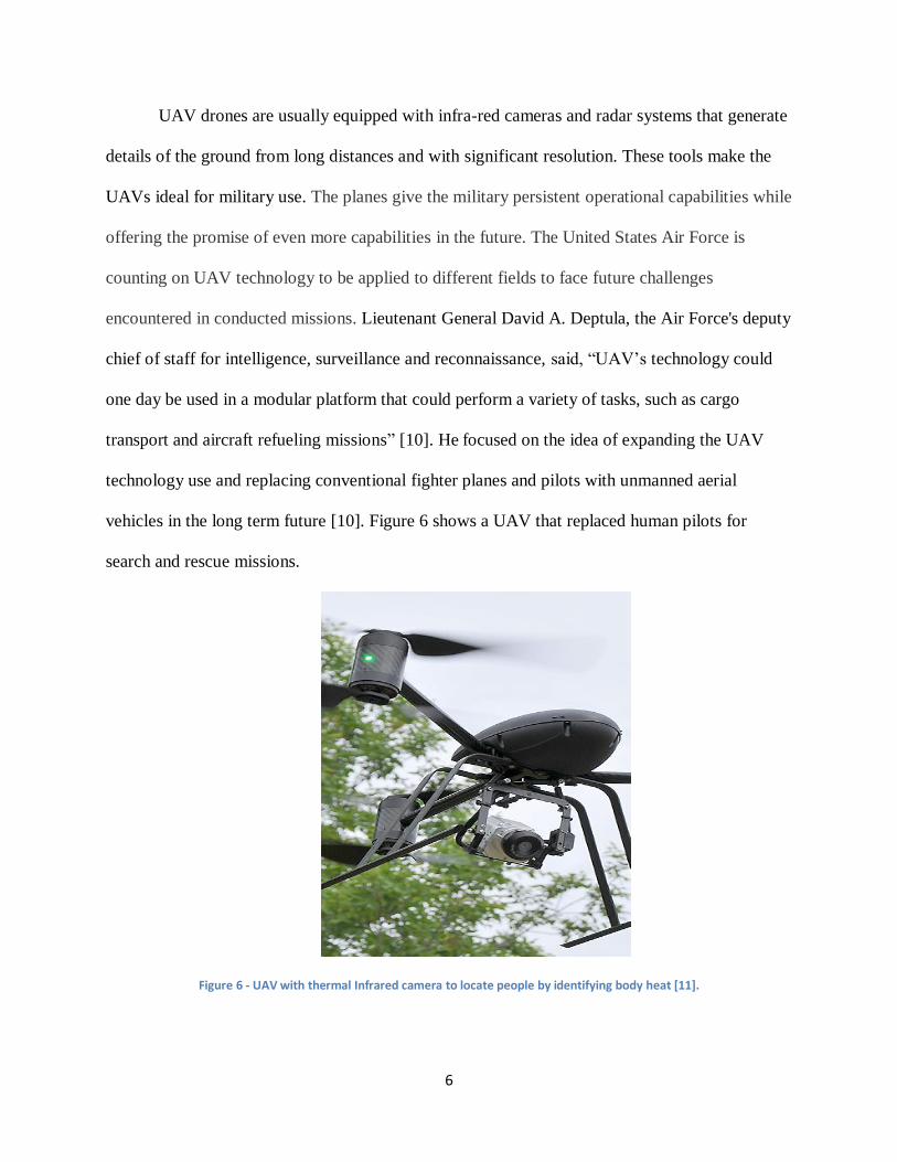
vehicles in the long term future [10]. Figure 6 shows a UAV that replaced human pilots for
search and rescue missions.
Figure 6 - UAV with thermal Infrared camera to locate people by identifying body heat [11].
7
All of this implies that more UAV applications in the future will be expected. UAVs will
reveal "sense and avoid" collision-avoidance systems by the end of this year [10]. They will be
able to refuel each other by 2030 and by 2047 a global military strike capability, perhaps even
with nuclear weapons, is expected for the UAVs. "As technology advances, machines will
automatically perform some repairs in flight," the Flight Plan reads. "Routine ground
maintenance will be conducted by machines without human touch labor," [10].
1.3. Benefits of UAVs
In this era of technology, people tend to create more machines and equipment that can
make their lives easier. The UAV is a perfect example for a rising technology field that’s
purpose is to serve humans. After many years of people questioning their usefulness, UAVs are
getting more attention from both scientists and investors.
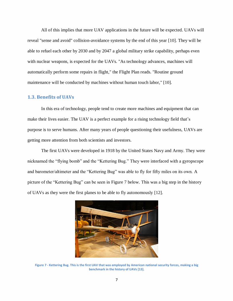
The first UAVs were developed in 1918 by the United States Navy and Army. They were
nicknamed the “flying bomb” and the “Kettering Bug.” They were interfaced with a gyropscope
and barometer/altimeter and the “Kettering Bug” was able to fly for fifty miles on its own. A
picture of the “Kettering Bug” can be seen in Figure 7 below. This was a big step in the history
of UAVs as they were the first planes to be able to fly autonomously [12].
Figure 7 - Kettering Bug. This is the first UAV that was employed by American national security forces, making a big benchmark in the history of UAVs [13].
8
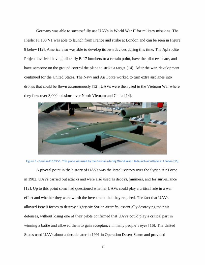
Germany was able to successfully use UAVs in World War II for military missions. The
Fiesler FI 103 V1 was able to launch from France and strike at London and can be seen in Figure
8 below [12]. America also was able to develop its own devices during this time. The Aphrodite
Project involved having pilots fly B-17 bombers to a certain point, have the pilot evacuate, and
have someone on the ground control the plane to strike a target [14]. After the war, development
continued for the United States. The Navy and Air Force worked to turn extra airplanes into
drones that could be flown autonomously [12]. UAVs were then used in the Vietnam War where
they flew over 3,000 missions over North Vietnam and China [14].
Figure 8 - German FI 103 V1. This plane was used by the Germans during World War II to launch air attacks at London [15].
A pivotal point in the history of UAVs was the Israeli victory over the Syrian Air Force
in 1982. UAVs carried out attacks and were also used as decoys, jammers, and for surveillance
[12]. Up to this point some had questioned whether UAVs could play a critical role in a war
effort and whether they were worth the investment that they required. The fact that UAVs
allowed Israeli forces to destroy eighty-six Syrian aircrafts, essentially destroying their air
defenses, without losing one of their pilots confirmed that UAVs could play a critical part in
winning a battle and allowed them to gain acceptance in many people’s eyes [16]. The United
States used UAVs about a decade later in 1991 in Operation Desert Storm and provided
9
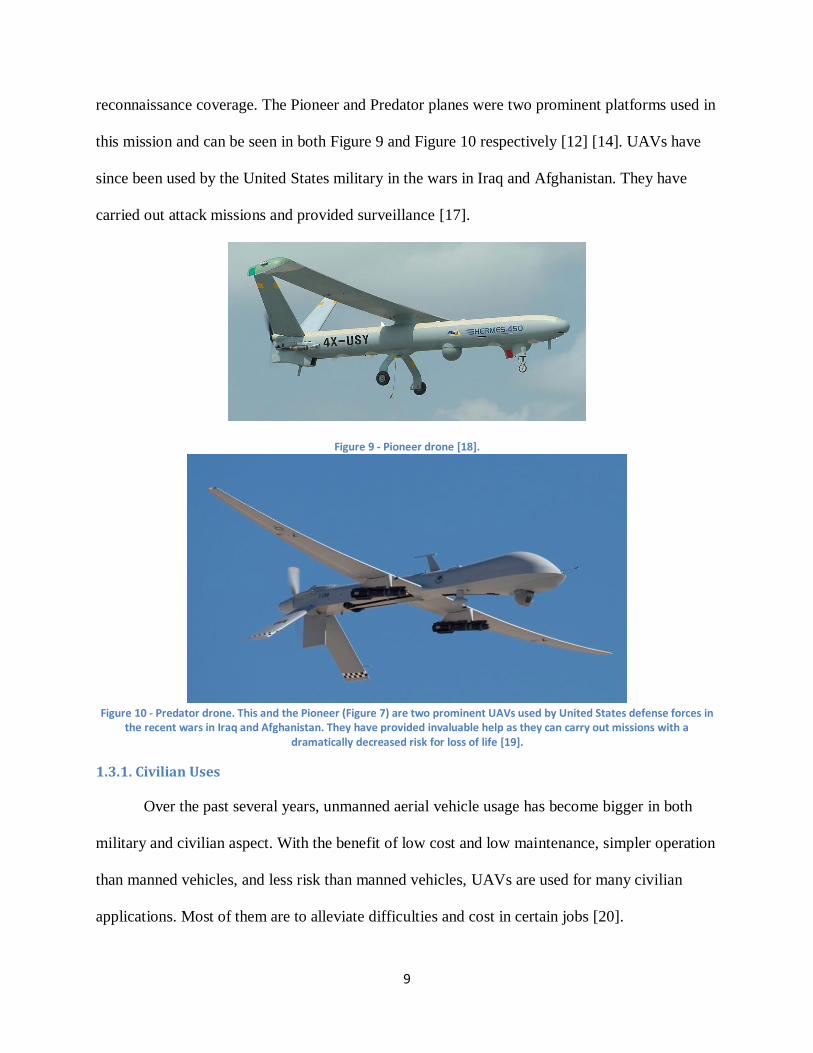
reconnaissance coverage. The Pioneer and Predator planes were two prominent platforms used in
this mission and can be seen in both Figure 9 and Figure 10 respectively [12] [14]. UAVs have
since been used by the United States military in the wars in Iraq and Afghanistan. They have
carried out attack missions and provided surveillance [17].
Figure 9 - Pioneer drone [18].
Figure 10 - Predator drone. This and the Pioneer (Figure 7) are two prominent UAVs used by United States defense forces in
the recent wars in Iraq and Afghanistan. They have provided invaluable help as they can carry out missions with a dramatically decreased risk for loss of life [19].
1.3.1. Civilian Uses
Over the past several years, unmanned aerial vehicle usage has become bigger in both
military and civilian aspect. With the benefit of low cost and low maintenance, simpler operation
than manned vehicles, and less risk than manned vehicles, UAVs are used for many civilian
applications. Most of them are to alleviate difficulties and cost in certain jobs [20].
10
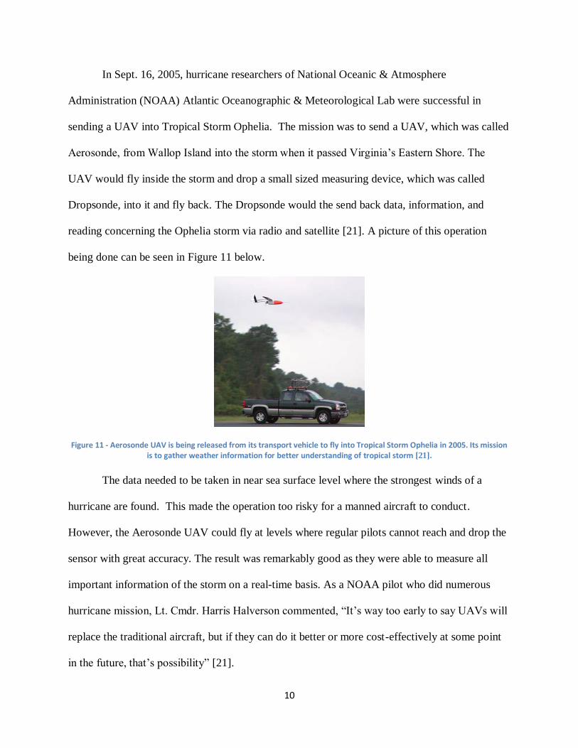
In Sept. 16, 2005, hurricane researchers of National Oceanic & Atmosphere
Administration (NOAA) Atlantic Oceanographic & Meteorological Lab were successful in
sending a UAV into Tropical Storm Ophelia. The mission was to send a UAV, which was called
Aerosonde, from Wallop Island into the storm when it passed Virginia’s Eastern Shore. The
UAV would fly inside the storm and drop a small sized measuring device, which was called
Dropsonde, into it and fly back. The Dropsonde would the send back data, information, and
reading concerning the Ophelia storm via radio and satellite [21]. A picture of this operation
being done can be seen in Figure 11 below.
Figure 11 - Aerosonde UAV is being released from its transport vehicle to fly into Tropical Storm Ophelia in 2005. Its mission is to gather weather information for better understanding of tropical storm [21].
The data needed to be taken in near sea surface level where the strongest winds of a
hurricane are found. This made the operation too risky for a manned aircraft to conduct.
However, the Aerosonde UAV could fly at levels where regular pilots cannot reach and drop the
sensor with great accuracy. The result was remarkably good as they were able to measure all
important information of the storm on a real-time basis. As a NOAA pilot who did numerous
hurricane mission, Lt. Cmdr. Harris Halverson commented, “It’s way too early to say UAVs will
replace the traditional aircraft, but if they can do it better or more cost-effectively at some point
in the future, that’s possibility” [21].
11
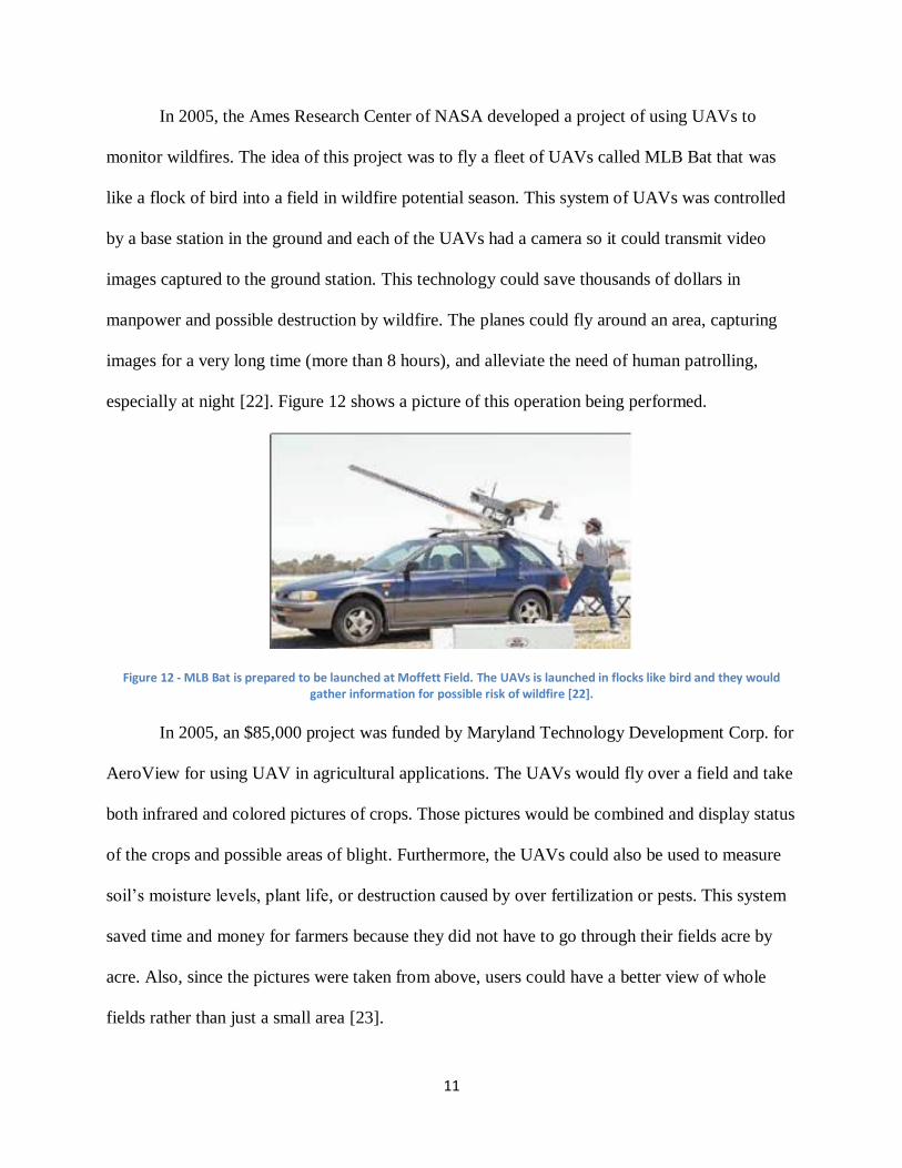
In 2005, the Ames Research Center of NASA developed a project of using UAVs to
monitor wildfires. The idea of this project was to fly a fleet of UAVs called MLB Bat that was
like a flock of bird into a field in wildfire potential season. This system of UAVs was controlled
by a base station in the ground and each of the UAVs had a camera so it could transmit video
images captured to the ground station. This technology could save thousands of dollars in
manpower and possible destruction by wildfire. The planes could fly around an area, capturing
images for a very long time (more than 8 hours), and alleviate the need of human patrolling,
especially at night [22]. Figure 12 shows a picture of this operation being performed.
Figure 12 - MLB Bat is prepared to be launched at Moffett Field. The UAVs is launched in flocks like bird and they would gather information for possible risk of wildfire [22].
In 2005, an $85,000 project was funded by Maryland Technology Development Corp. for
AeroView for using UAV in agricultural applications. The UAVs would fly over a field and take
both infrared and colored pictures of crops. Those pictures would be combined and display status
of the crops and possible areas of blight. Furthermore, the UAVs could also be used to measure
soil’s moisture levels, plant life, or destruction caused by over fertilization or pests. This system
saved time and money for farmers because they did not have to go through their fields acre by
acre. Also, since the pictures were taken from above, users could have a better view of whole
fields rather than just a small area [23].
12
1.3.2. National Defense Uses
Historically, UAVs have been mostly used in military situations. Since their inception
they have provided many advantages over traditional airplanes. UAVs are safer, less expensive,
and more environmentally friendly than their counterparts. They are capable of executing
missions that manned aircraft cannot and can be controlled remotely. The advantages of UAVs
in military missions are numerous.
UAVs also provide a major cost advantage over similar alternative vehicles. A Reaper or
Sky Warrior, two common UAVs used by the United States military, cost about $22 million
apiece on average. In contrast the Pentagon pays about $100 million per fighter jet purchased.
Thus a Reaper or Sky Warrior provides over a 75% savings from traditional military aircraft
[24]. A pilot is also not needed to fly a UAV therefore providing extra savings. The upkeep of
UAVs is also less than that of regular manned vehicles and can be flown out of smaller airports
which cost less to use than bigger ones. The economic savings that UAVs provide is a very key
advantage of theirs [24].
The use of UAVs also provides certain flexibility during missions that regular planes do
not have. Since many countries do not require UAV operators to be fully qualified, more people
are able to operate them for missions [25]. Also, because of their small size they can fly lower
than traditional aircraft and are capable of taking high resolution video, which other planes
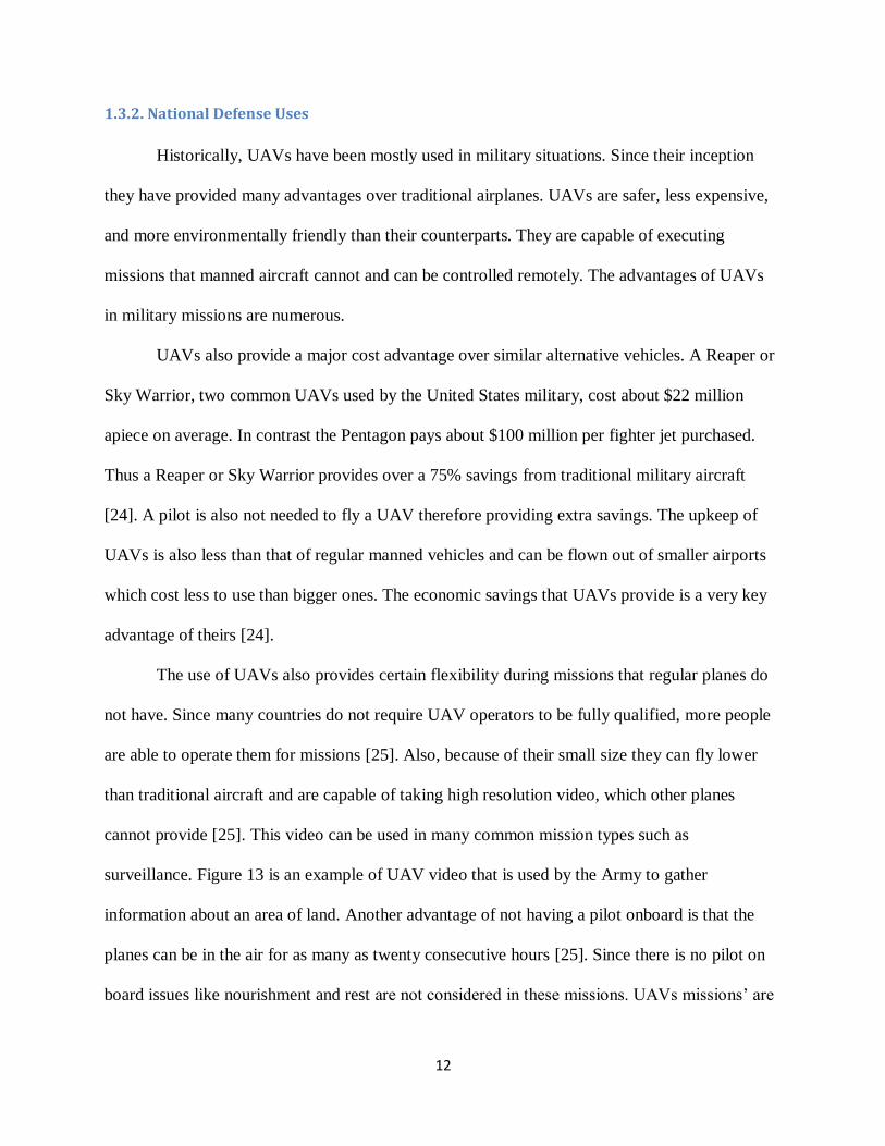
cannot provide [25]. This video can be used in many common mission types such as
surveillance. Figure 13 is an example of UAV video that is used by the Army to gather
information about an area of land. Another advantage of not having a pilot onboard is that the
planes can be in the air for as many as twenty consecutive hours [25]. Since there is no pilot on
board issues like nourishment and rest are not considered in these missions. UAVs missions’ are
13
also normally very repetitive and dull when they are in the air for this long of a period of time.
Normally this would drive a human operator to distraction that could have a negative impact on
the mission’s performance. With no operator on board however this is not an issue. UAVs also
provide other advantages because they feature autonomous control. Autopilot and navigation
systems allow UAVs to take off, fly, and land under computer control. This allows the operators
to program them with flight patterns so that many of them can fly in the same area without the
worry of crashing [25].
Figure 13 - Video feed of U.S. Army UAVs. This video was used to spy on OPFOR mounted elements, which is a group designated to simulate the enemy in preparation for battle. This screenshot proves how defense teams can use video from
UAVs to watch enemy movement [26].
Another often overlooked factor in the advantages of UAVs is that they are more
environmentally friendly than traditional aircraft. These planes require fewer materials to build
and less gas to run thus conserving natural resources. They also create release less carbon
dioxide into the atmosphere during flight, which reduces the amount of greenhouse gases in the
atmosphere. Other considerations include the fact that they make less noise than regular planes
and are easier to dispose of once they are out of use [25].
UAVs are safer to operate and reduce the chance at a loss of life during mission runs.
They also are able to fly over areas where it would be too dangerous to send regular aircraft.
14
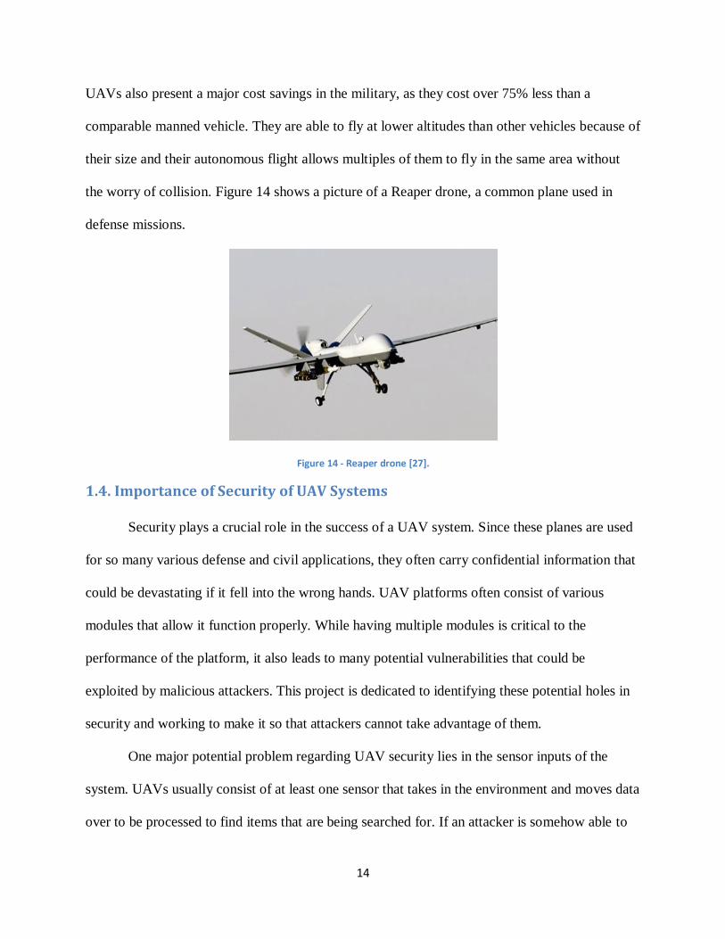
UAVs also present a major cost savings in the military, as they cost over 75% less than a
comparable manned vehicle. They are able to fly at lower altitudes than other vehicles because of
their size and their autonomous flight allows multiples of them to fly in the same area without
the worry of collision. Figure 14 shows a picture of a Reaper drone, a common plane used in
defense missions.
Figure 14 - Reaper drone [27].
1.4. Importance of Security of UAV Systems
Security plays a crucial role in the success of a UAV system. Since these planes are used
for so many various defense and civil applications, they often carry confidential information that
could be devastating if it fell into the wrong hands. UAV platforms often consist of various
modules that allow it function properly. While having multiple modules is critical to the
performance of the platform, it also leads to many potential vulnerabilities that could be
exploited by malicious attackers. This project is dedicated to identifying these potential holes in
security and working to make it so that attackers cannot take advantage of them.
One major potential problem regarding UAV security lies in the sensor inputs of the
system. UAVs usually consist of at least one sensor that takes in the environment and moves data
over to be processed to find items that are being searched for. If an attacker is somehow able to
15
tamper with this input to make the sensor see something that is not there, the effectiveness of the
mission will be compromised. This could lead the team controlling the UAV to react to
something they should not, while at the same time not identifying an item that should be
identified because they are preoccupied with the false one. An example of this could be a UAV
being used in a search and rescue mission with a camera programmed to identify red colored
objects on the ground. If an attacker could shine a light on the lens of the camera, it could cause
the image processing module to either identify the light as an object on the ground or be blinded
and not process any images at all. Another potential example is interfering with the global
positioning system (GPS) module of the UAV. Many drones carry GPS modules to let users
identify their location. If someone was able to jam the module so that it outputted the wrong
position coordinates it would seriously hinder the reliability of the UAV system.
Another potential vulnerability lies in the communications module of UAVs. Since
UAVs are flown in the air and controlled on the ground, most of them feature some sort of
wireless communication to transmit important data and commands in a bidirectional manner.
Some common methods include Wi-Fi, Zigbee radios, and Bluetooth [28]. While this feature is
critical to UAV functionality, it also presents a major risk as wireless signals always have the
chance of being interfered with or intercepted. Software currently exists that is able to intercept
messages being sent between servers. This presents an imminent danger because if an enemy
was able to get a hold of critical information they could maneuver themselves so that they are out
of danger of the UAV control team. Another threat that exists regarding wireless communication
is the jamming of the signals. One popular way to jam signals is by sending packets to one server
that are full of meaningless data. This will keep the server so busy that it will not be able to listen
to relevant data coming from the other communication module. This presents a problem to the
16
control team as it would lose control of the plane and not be able to obtain the data that it is
transmitting. Much care must be taken as to make sure that the communication component of the
UAV system cannot be compromised.
Keeping a UAV system secure is very important to any team that is working with them.
While the complexity of UAVs leads to their effective performance, it also presents multiple
issues that can be exploited by malicious attackers. This threat is compounded when the planes
are being used for defense missions where a breakdown in security can be the difference between
life and death. Extra caution must be taken when designing UAV systems as to make sure that
they are not open to attacks.
1.5. Proposed Approach
During the course of this project, an architecture for a UAV platform was developed and
ways were found to protect it against malicious attacks. The UAV architecture consists of
multiple modules and is capable of capturing images, processing those images, and sending the
processed data between the UAV in the air and the station on the ground. The platform is based
on previous projects conducted at Worcester Polytechnic Institute [29], Massachusetts Institute
of Technology [30], Brigham Young University [31], and Linkoping University [32]. The main
components include an autopilot system for navigation, a microprocessor for image processing, a
ground control system, a camera, and a communication system for communicating with the
ground control system. Off-the-shelf items were considered for these components.
Multiple components and their interfacing with one another were able to be compared by
looking at projects. Value analysis was conducted on the different components and methods of
communication and a finalized structure was determined for this system. Multiple various
architectures were compared to determine the best way to design this platform. Once a design
17
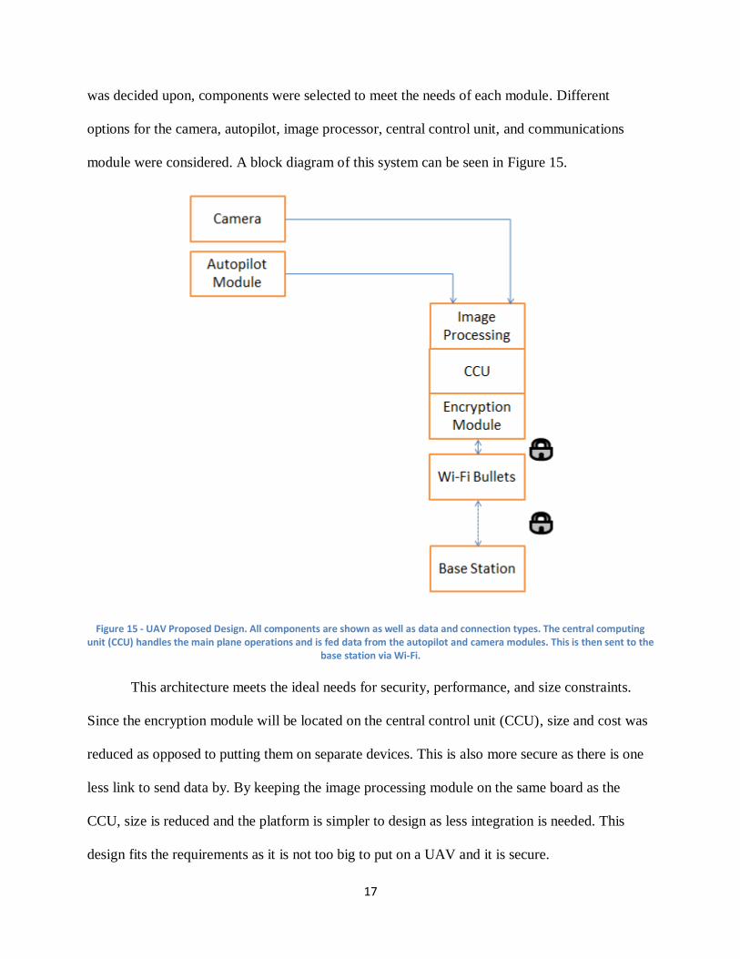
was decided upon, components were selected to meet the needs of each module. Different
options for the camera, autopilot, image processor, central control unit, and communications
module were considered. A block diagram of this system can be seen in Figure 15.
Figure 15 - UAV Proposed Design. All components are shown as well as data and connection types. The central computing unit (CCU) handles the main plane operations and is fed data from the autopilot and camera modules. This is then sent to the
base station via Wi-Fi.
This architecture meets the ideal needs for security, performance, and size constraints.
Since the encryption module will be located on the central control unit (CCU), size and cost was
reduced as opposed to putting them on separate devices. This is also more secure as there is one
less link to send data by. By keeping the image processing module on the same board as the
CCU, size is reduced and the platform is simpler to design as less integration is needed. This
design fits the requirements as it is not too big to put on a UAV and it is secure.
18
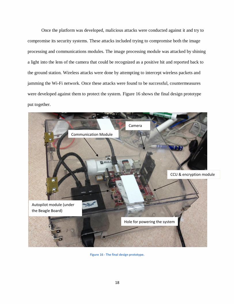
Once the platform was developed, malicious attacks were conducted against it and try to
compromise its security systems. These attacks included trying to compromise both the image
processing and communications modules. The image processing module was attacked by shining
a light into the lens of the camera that could be recognized as a positive hit and reported back to
the ground station. Wireless attacks were done by attempting to intercept wireless packets and
jamming the Wi-Fi network. Once these attacks were found to be successful, countermeasures
were developed against them to protect the system. Figure 16 shows the final design prototype
put together.
Figure 16 - The final design prototype.
Hole for powering the system
CCU & encryption module
Camera
Communication Module
Autopilot module (under
the Beagle Board)
19
1.6. Authorship
Each team member played a crucial in the completion of this project. Each person’s
contribution is shown below:
Phuoc Luong wrote about the applications and history of UAVs. He wrote about current
security and computing architecture of UAVs. Furthermore, he worked on some portions
of the market research of processor choices and did the image processing value analysis.
Phuoc also programmed the image processing algorithm as well as socket programming.
Finally, he was in charge of testing the colored light attack and providing counter
measurement against this type of attack.
Roni Rostom wrote about the importance of UAVs and UAV markets. Roni Rostom also
researched about the different communication modules used in past UAV projects to
transfer data between the UAVs in the air and the ground base stations, and did a value
analysis to choose the best module for this system. Roni also worked on configuring the
right settings of the Wi-Fi bullets and assisted in successfully running the socket
programming codes for the wireless communication. He also was involved in the wireless
hacking attacks that made use of the Wireshark software and wrote about it in the report.
Evan Ziavras wrote the about the applications for UAVs in the civilian and defense
fields. He also conducted research about autopilot modules and cameras used in past
UAV projects and conducted value analysis to decide one the ones that were to be used in
this project. Evan also worked on configuring the autopilot module with the Beagleboard
and installed the virtual machine to run the socket programming between the platform
and ground station. He also was involved in the wireless jamming attacks that made use
of Aircrack-ng and wrote about these parts in the report.
20
1.5. Report Organization
This chapter has shown the problem statement and motivation for the project as well as a
low-level proposed approach for its implantation. In Chapter 2, background about history of
UAVs is given as well design options and prior art. Chapter 3 describes the proposed approach
and value analysis for the different components considered for this project. The implementation
process is given in Chapter 4 and the final results and discussion are covered in Chapter 5.
Chapter 6 states all of the conclusions and recommended future work for this project.
21
2. Overview of UAV Systems
Information is very important when working on a project, especially in a technical area
such as UAVs are in. Therefore, before starting the implementation process, more needs to be
learned about the current status of UAVs, the UAV market, and information about popular UAV
components. This process will make the scope of the project clearer, helping organizing project
resources.
2.1. History of UAVs
Ever since the beginning of humanities flying was a never ending desire of people. There
have been countless number of attempts to fly in both history and legend; some of them were
very famous like “the story of Daedalus and Icarus” or Da Vinci’s flying machine. However,
aerial vehicles’ history formally started when the Wright brothers first succeeded in giving
humans the ability to fly in 1903. Since then, a whole new world of possibilities and dreams has
opened up. UAV history can be dated to as back from the advent of the first flight, but none of
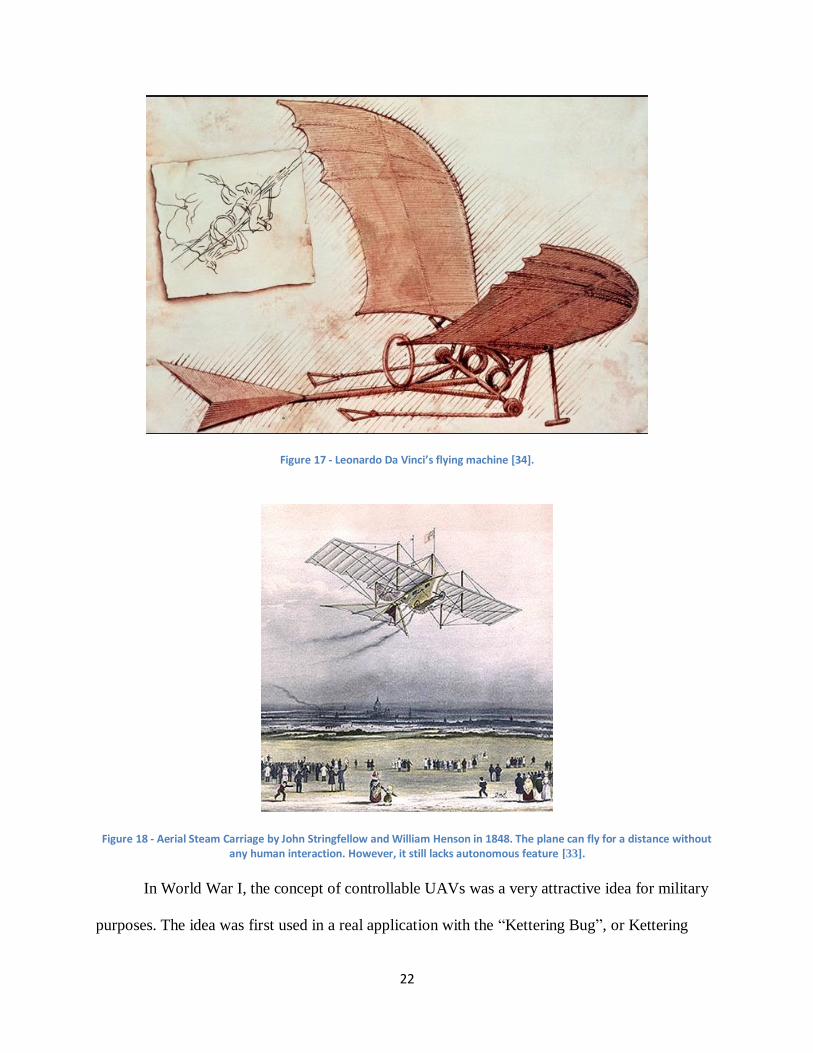
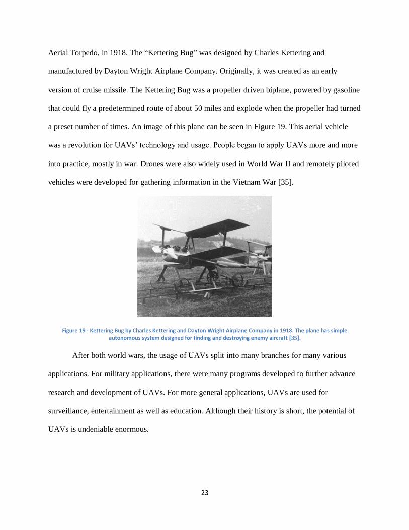
the attempted inventions were truly autonomous or controllable. Notably, there were John
Stringfellow and William Henson who created a steam powered aircraft called Aerial Steam
Carriage in 1848 that could fly for a distance of about 60 yards [33]. Figure 17 and Figure 18
show drawings of these two primitive flying machines.
22
Figure 17 - Leonardo Da Vinci’s flying machine [34].
Figure 18 - Aerial Steam Carriage by John Stringfellow and William Henson in 1848. The plane can fly for a distance without any human interaction. However, it still lacks autonomous feature [33].
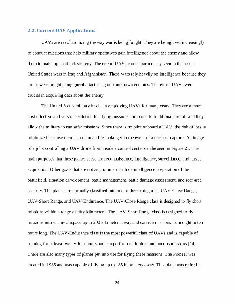
In World War I, the concept of controllable UAVs was a very attractive idea for military
purposes. The idea was first used in a real application with the “Kettering Bug”, or Kettering
23
Aerial Torpedo, in 1918. The “Kettering Bug” was designed by Charles Kettering and
manufactured by Dayton Wright Airplane Company. Originally, it was created as an early
version of cruise missile. The Kettering Bug was a propeller driven biplane, powered by gasoline
that could fly a predetermined route of about 50 miles and explode when the propeller had turned
a preset number of times. An image of this plane can be seen in Figure 19. This aerial vehicle
was a revolution for UAVs’ technology and usage. People began to apply UAVs more and more
into practice, mostly in war. Drones were also widely used in World War II and remotely piloted
vehicles were developed for gathering information in the Vietnam War [35].
Figure 19 - Kettering Bug by Charles Kettering and Dayton Wright Airplane Company in 1918. The plane has simple autonomous system designed for finding and destroying enemy aircraft [35].
After both world wars, the usage of UAVs split into many branches for many various
applications. For military applications, there were many programs developed to further advance
research and development of UAVs. For more general applications, UAVs are used for
surveillance, entertainment as well as education. Although their history is short, the potential of
UAVs is undeniable enormous.
24
2.2. Current UAV Applications
UAVs are revolutionizing the way war is being fought. They are being used increasingly
to conduct missions that help military operatives gain intelligence about the enemy and allow
them to make up an attack strategy. The rise of UAVs can be particularly seen in the recent
United States wars in Iraq and Afghanistan. These wars rely heavily on intelligence because they
are or were fought using guerilla tactics against unknown enemies. Therefore, UAVs were
crucial in acquiring data about the enemy.
The United States military has been employing UAVs for many years. They are a more
cost effective and versatile solution for flying missions compared to traditional aircraft and they
allow the military to run safer missions. Since there is no pilot onboard a UAV, the risk of loss is
minimized because there is no human life in danger in the event of a crash or capture. An image
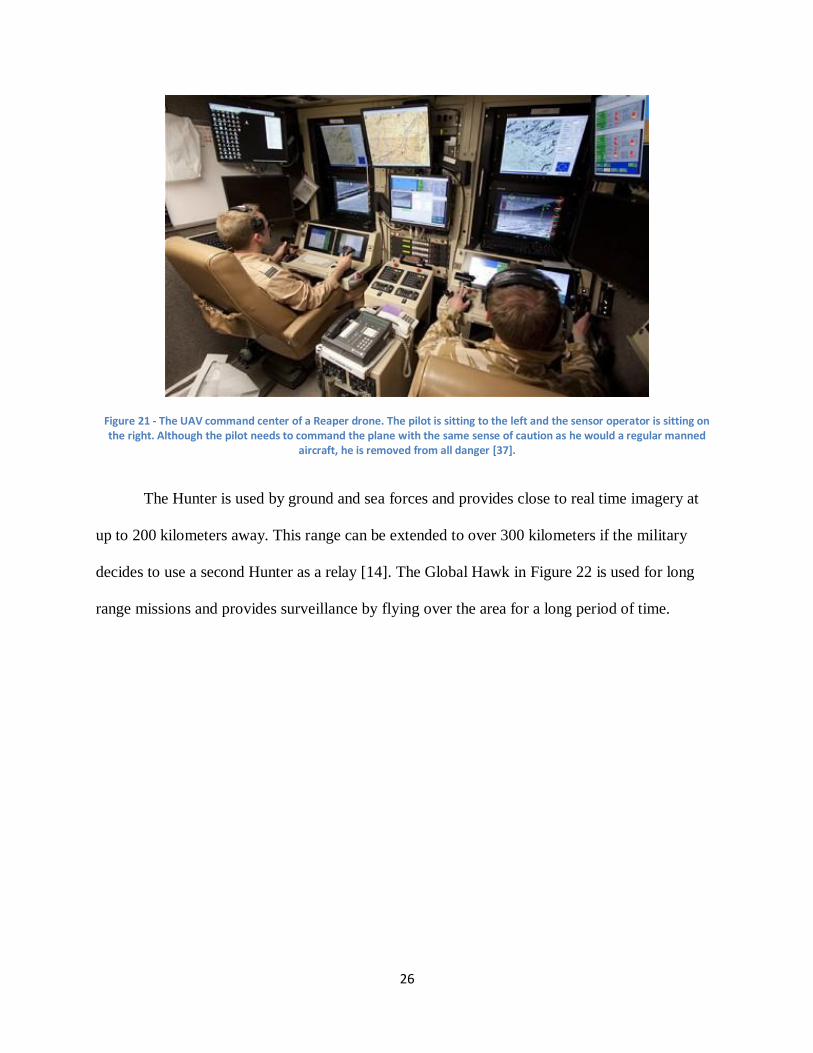
of a pilot controlling a UAV drone from inside a control center can be seen in Figure 21. The
main purposes that these planes serve are reconnaissance, intelligence, surveillance, and target
acquisition. Other goals that are not as prominent include intelligence preparation of the
battlefield, situation development, battle management, battle damage assessment, and rear area
security. The planes are normally classified into one of three categories, UAV-Close Range,
UAV-Short Range, and UAV-Endurance. The UAV-Close Range class is designed to fly short
missions within a range of fifty kilometers. The UAV-Short Range class is designed to fly
missions into enemy airspace up to 200 kilometers away and can run missions from eight to ten
hours long. The UAV-Endurance class is the most powerful class of UAVs and is capable of
running for at least twenty-four hours and can perform multiple simultaneous missions [14].
There are also many types of planes put into use for flying these missions. The Pioneer was
created in 1985 and was capable of flying up to 185 kilometers away. This plane was retired in
25
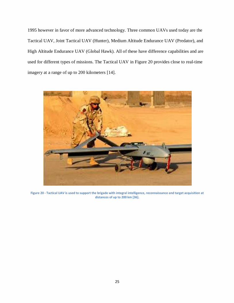
1995 however in favor of more advanced technology. Three common UAVs used today are the
Tactical UAV, Joint Tactical UAV (Hunter), Medium Altitude Endurance UAV (Predator), and
High Altitude Endurance UAV (Global Hawk). All of these have difference capabilities and are
used for different types of missions. The Tactical UAV in Figure 20 provides close to real-time
imagery at a range of up to 200 kilometers [14].
Figure 20 - Tactical UAV is used to support the brigade with integral intelligence, reconnaissance and target acquisition at distances of up to 200 km [36].
26
Figure 21 - The UAV command center of a Reaper drone. The pilot is sitting to the left and the sensor operator is sitting on the right. Although the pilot needs to command the plane with the same sense of caution as he would a regular manned
aircraft, he is removed from all danger [37].
The Hunter is used by ground and sea forces and provides close to real time imagery at
up to 200 kilometers away. This range can be extended to over 300 kilometers if the military
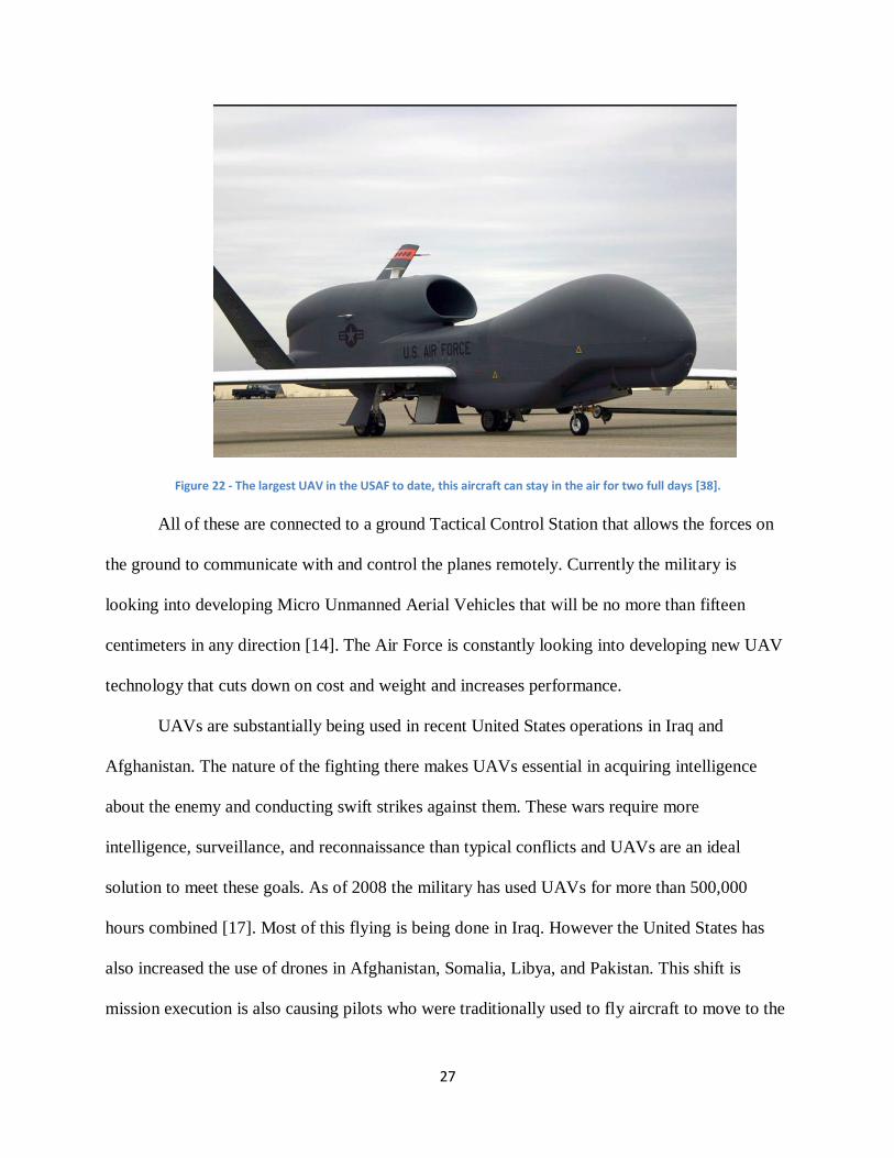
decides to use a second Hunter as a relay [14]. The Global Hawk in Figure 22 is used for long
range missions and provides surveillance by flying over the area for a long period of time.
27
Figure 22 - The largest UAV in the USAF to date, this aircraft can stay in the air for two full days [38].
All of these are connected to a ground Tactical Control Station that allows the forces on
the ground to communicate with and control the planes remotely. Currently the military is
looking into developing Micro Unmanned Aerial Vehicles that will be no more than fifteen
centimeters in any direction [14]. The Air Force is constantly looking into developing new UAV
technology that cuts down on cost and weight and increases performance.
UAVs are substantially being used in recent United States operations in Iraq and
Afghanistan. The nature of the fighting there makes UAVs essential in acquiring intelligence
about the enemy and conducting swift strikes against them. These wars require more
intelligence, surveillance, and reconnaissance than typical conflicts and UAVs are an ideal
solution to meet these goals. As of 2008 the military has used UAVs for more than 500,000
hours combined [17]. Most of this flying is being done in Iraq. However the United States has
also increased the use of drones in Afghanistan, Somalia, Libya, and Pakistan. This shift is
mission execution is also causing pilots who were traditionally used to fly aircraft to move to the
28
ground to operate the UAVs. As of 2008, 120 pilots were removed from flying duties and moved
to ground stations [17]. Not all of this flying is data gathering missions however. UAVs are also
able to carry out strikes against enemies. In Iraq, a Predator plane was able to locate militants
firing mortar and fired a missile killing them both. In total, Reaper and Predator drones have
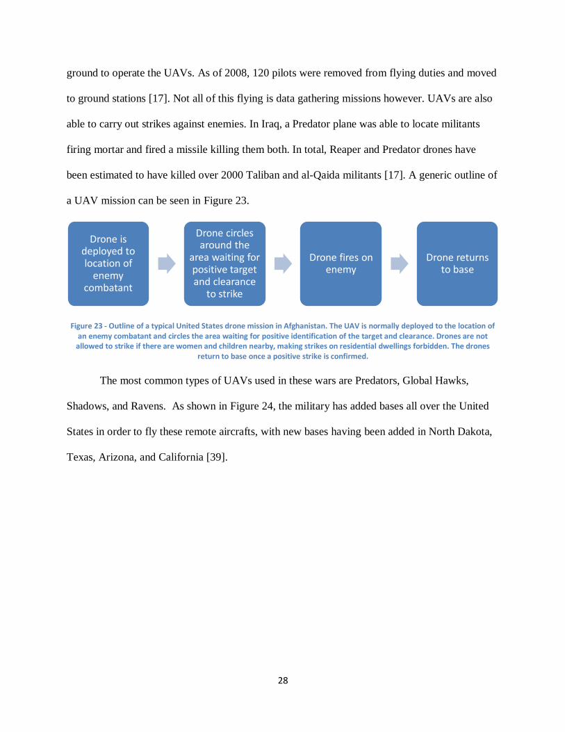
been estimated to have killed over 2000 Taliban and al-Qaida militants [17]. A generic outline of
a UAV mission can be seen in Figure 23.
Figure 23 - Outline of a typical United States drone mission in Afghanistan. The UAV is normally deployed to the location of an enemy combatant and circles the area waiting for positive identification of the target and clearance. Drones are not
allowed to strike if there are women and children nearby, making strikes on residential dwellings forbidden. The drones return to base once a positive strike is confirmed.
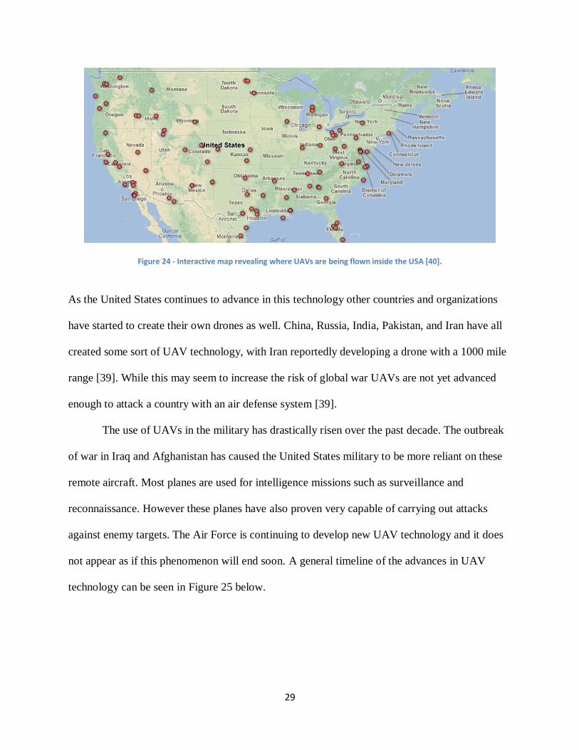
The most common types of UAVs used in these wars are Predators, Global Hawks,
Shadows, and Ravens. As shown in Figure 24, the military has added bases all over the United
States in order to fly these remote aircrafts, with new bases having been added in North Dakota,
Texas, Arizona, and California [39].
Drone is deployed to location of
enemy combatant
Drone circles around the
area waiting for positive target and clearance
to strike
Drone fires on enemy
Drone returns to base
29
Figure 24 - Interactive map revealing where UAVs are being flown inside the USA [40].
As the United States continues to advance in this technology other countries and organizations
have started to create their own drones as well. China, Russia, India, Pakistan, and Iran have all
created some sort of UAV technology, with Iran reportedly developing a drone with a 1000 mile
range [39]. While this may seem to increase the risk of global war UAVs are not yet advanced
enough to attack a country with an air defense system [39].
The use of UAVs in the military has drastically risen over the past decade. The outbreak
of war in Iraq and Afghanistan has caused the United States military to be more reliant on these
remote aircraft. Most planes are used for intelligence missions such as surveillance and
reconnaissance. However these planes have also proven very capable of carrying out attacks
against enemy targets. The Air Force is continuing to develop new UAV technology and it does
not appear as if this phenomenon will end soon. A general timeline of the advances in UAV
technology can be seen in Figure 25 below.
30
Figure 25 - A timeline of the rise of the use of UAVs. As can be seen above, UAVs started to be used in serious defense applications in World War II. Their use increased as time went on and after Israel used them to destroy the Syrian air
defenses in 1982 the United States decided to start investing heavily in the technology. During the war in Afghanistan the United States had 3,000 drones in service. That number has increased to 12,000 as of 2010 [41].
UAVs are used in the agricultural market for precision agricultural and environmental
scanning. The planes are able to be sent in the air and take pictures of crops in both infrared and
visible-light frequencies. When these images are passed through an algorithm they can be color
coded to see which areas are growing well and which are growing poorly. Based on the results of
this data a variable rate applicator is adjusted to spray the areas that need more growth more than
the areas where growth is relatively poor. UAVs are also used to measure the moisture levels of
soil, the amount of plant life in soil, and runoff caused by over fertilization or animals.
Unmanned aerial vehicles are a good solution to these problems as they are not affected by bad
weather since they fly beneath the clouds to be able to take more detailed pictures than normal
[42]. Figure 26 shows a plane performing crop monitoring.
31
Figure 26 - Autonomous Platform for Precision Agriculture (APPA) is an UAV developed by University of Arkansas System. The UAV was developed with purpose of better crop management and nurseries [43].
UAVs are also very useful for monitoring the spread of wildfires. These present a very
versatile option as they are able to fly in the air for over eight hours at a time and are capable of
flying at nighttime. This task is assigned to a group of planes that are programmed to simulate
the flight of a flock of birds. The planes take video of the terrain and transmit it to the firefighters
on the ground so that they can locate where the fire is strong and deploy their men appropriately.
The UAVs are also capable of locating lighting storms after a summer rainstorm and can also
investigate toxic chemical spills or radiological accidents [22]. A UAV performing a wildfire
monitoring mission can be seen in Figure 27.
Figure 27 - An unmanned aerial vehicle developed by NASA in wildfire detection testing [44].
32
Another area where UAVs play a prominent role is in the field of meteorology. One of
the most useful tasks done in this area is hurricane research. Since they do not risk the loss of
human life, UAVs can safely fly into a hurricane and measure pressure, humidity, waves, and
wind. This results in more accurate forecasts that can save more civilian lives. The United States
military has been employing this technology since 1950 and its use continues to grow. The
planes capture data by dropping dropsonodes, small cylinder sensors, on to the ground. The
dropsonodes relay information about the weather back to the aircraft which relays it to the team
controlling it from the ground [45]. A plane performing this operation is shown in Figure 28.
Figure 28 - A UAV launched into a hurricane in 2008. The purpose was to know more about hurricane’s characteristics [46].
UAVs are also a very useful tool to use in disaster response. The military once used a
UAV during a simulated terrorist attack and it proved to provide good results. A terrorist attack
was simulated in Silicon Valley, California and a UAV was flown in as first response and was
used to located suspicious vehicles on the road. The plane was able to provide aerial surveillance
data by using color and thermal infrared digital cameras, a color videocam, and a chemical
33
sensor. A picture of this UAV is shown in Figure 29. The analyst operating the plane was able to
locate the suspicious vehicles using the red/blue/green signals transmitted to him [47].
Figure 29 - Launching of RQ-11 Mini-UAV, an UAV that is used for identify possible threats. The UAV acts as second security layer after the first layer of ground sensor [48].
One area where UAVs are most useful is in search and rescue missions. Search and
rescue is traditionally done in the wilderness to find people that have gone missing, such as
hikers. Normally this is a very costly and dangerous procedure, as rescuers need to trained and
compensated. It is dangerous because hikers are normally lost in hazardous and hard to get to
terrain. Sending in people after them is risky as it exposes them to the same risks that the hikers
have been subjected to. UAVs solve this issue by being sent to fly over the terrain that is being
searched. On-board cameras can get visual images of the area below and run image processing
algorithms on the video images to detect any background disturbances. The algorithm can detect
whether the disturbance detected is a human and the ground crew can send rescuers to that area.
This saves time and resources in that it can search a wider area quicker than traditional methods
and it is not necessary to send in humans until the location of the lost hikers have been
pinpointed. An image of a UAV used to perform search and rescue missions is shown in Figure
30. This is much safer than sending humans to physically search the area [29].
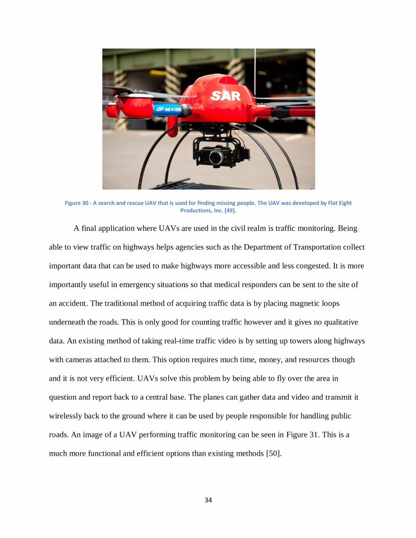
34
Figure 30 - A search and rescue UAV that is used for finding missing people. The UAV was developed by Flat Eight Productions, Inc. [49].
A final application where UAVs are used in the civil realm is traffic monitoring. Being
able to view traffic on highways helps agencies such as the Department of Transportation collect
important data that can be used to make highways more accessible and less congested. It is more
importantly useful in emergency situations so that medical responders can be sent to the site of
an accident. The traditional method of acquiring traffic data is by placing magnetic loops
underneath the roads. This is only good for counting traffic however and it gives no qualitative
data. An existing method of taking real-time traffic video is by setting up towers along highways
with cameras attached to them. This option requires much time, money, and resources though
and it is not very efficient. UAVs solve this problem by being able to fly over the area in
question and report back to a central base. The planes can gather data and video and transmit it
wirelessly back to the ground where it can be used by people responsible for handling public
roads. An image of a UAV performing traffic monitoring can be seen in Figure 31. This is a
much more functional and efficient options than existing methods [50].
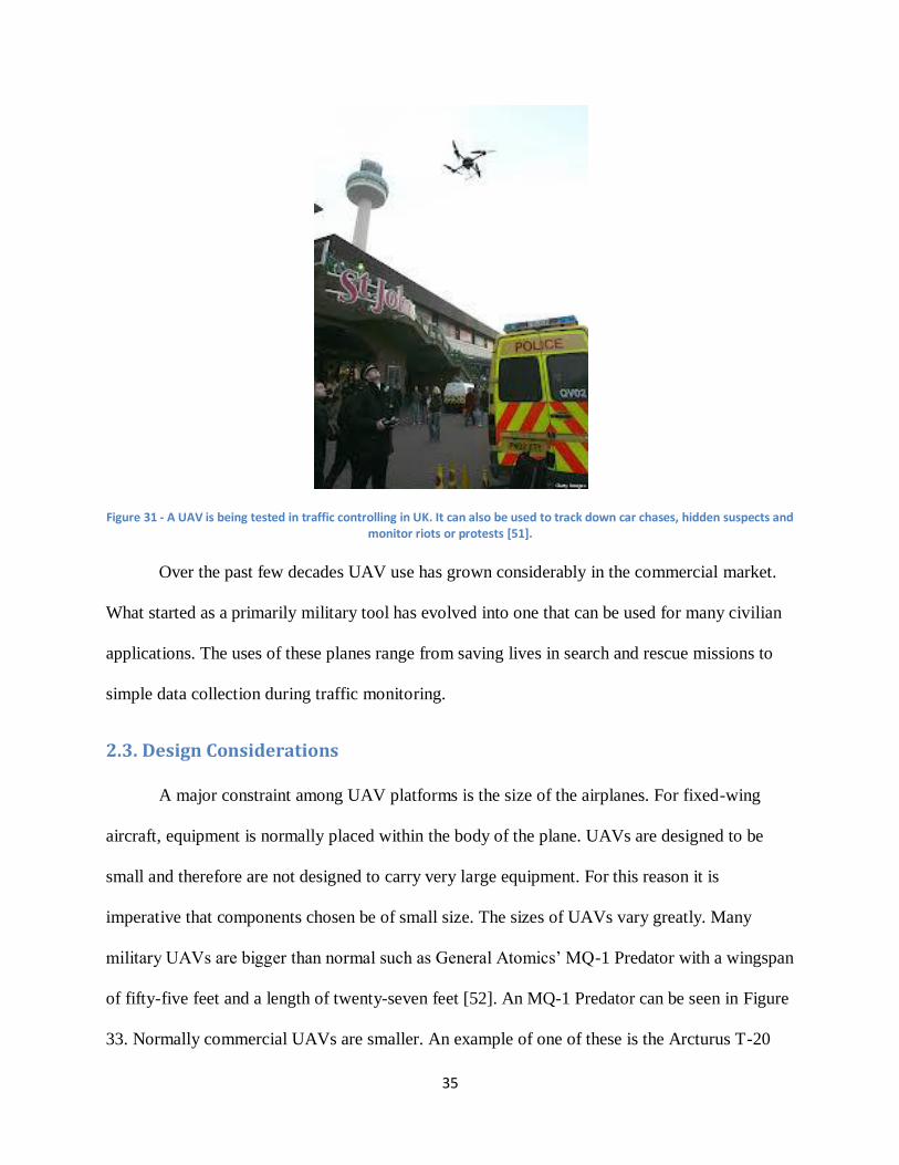
35
Figure 31 - A UAV is being tested in traffic controlling in UK. It can also be used to track down car chases, hidden suspects and monitor riots or protests [51].
Over the past few decades UAV use has grown considerably in the commercial market.
What started as a primarily military tool has evolved into one that can be used for many civilian
applications. The uses of these planes range from saving lives in search and rescue missions to
simple data collection during traffic monitoring.
2.3. Design Considerations
A major constraint among UAV platforms is the size of the airplanes. For fixed-wing
aircraft, equipment is normally placed within the body of the plane. UAVs are designed to be
small and therefore are not designed to carry very large equipment. For this reason it is
imperative that components chosen be of small size. The sizes of UAVs vary greatly. Many
military UAVs are bigger than normal such as General Atomics’ MQ-1 Predator with a wingspan
of fifty-five feet and a length of twenty-seven feet [52]. An MQ-1 Predator can be seen in Figure
33. Normally commercial UAVs are smaller. An example of one of these is the Arcturus T-20
36
with a wingspan of seventeen and a half feet and a length of nine and a half feet [53]. Even
smaller are UAVs that are built as student projects. The Goose UAV from Worcester Polytechnic
Institute has a wingspan of six feet and a body area of 2.16 square feet [29]. For this reason it is
crucial to select small hardware components when designing a system that is to be put onto a
UAV platform. Regarding the power constraints, and depending on the power source available,
the power generated can range from 102 watts for small UAV systems like the Goose to up to 48
kilowatts for superior UAV systems like the Predator.
Weight constraint is also a very important factor for every aerial vehicle which largely
influences the design process. This is more vital for UAVs due to their small size. Weight does
not only affect the UAV’s speed but also has very big impact on power budget and overall
performance of the UAV. Platform designers need to consider all factors to make the UAV as
light as possible. Consequently the system for this project must fit into a regularly sized UAV.
As UAVs’ purposes differ in many areas, UAVs’ weight also has very big range. For example,
the Arcturus UAV, which is used for simple surveillance, has maximum weight of 75 pounds
(about 35 kilograms), while the MQ-4C Triton that is used for marine intelligence gathering has
a gigantic weight of more than 14,000 kilogram [52] [53]. However, as this project is in smaller
scale, it is more focused toward small size UAVs that range between 20 kilograms and 100
kilograms.
These examples as well as three other prominent UAVs are summarized in Table 1 and
the scatter plot in Figure 32. This shows the wide range of design specifications with which
UAVs are built.
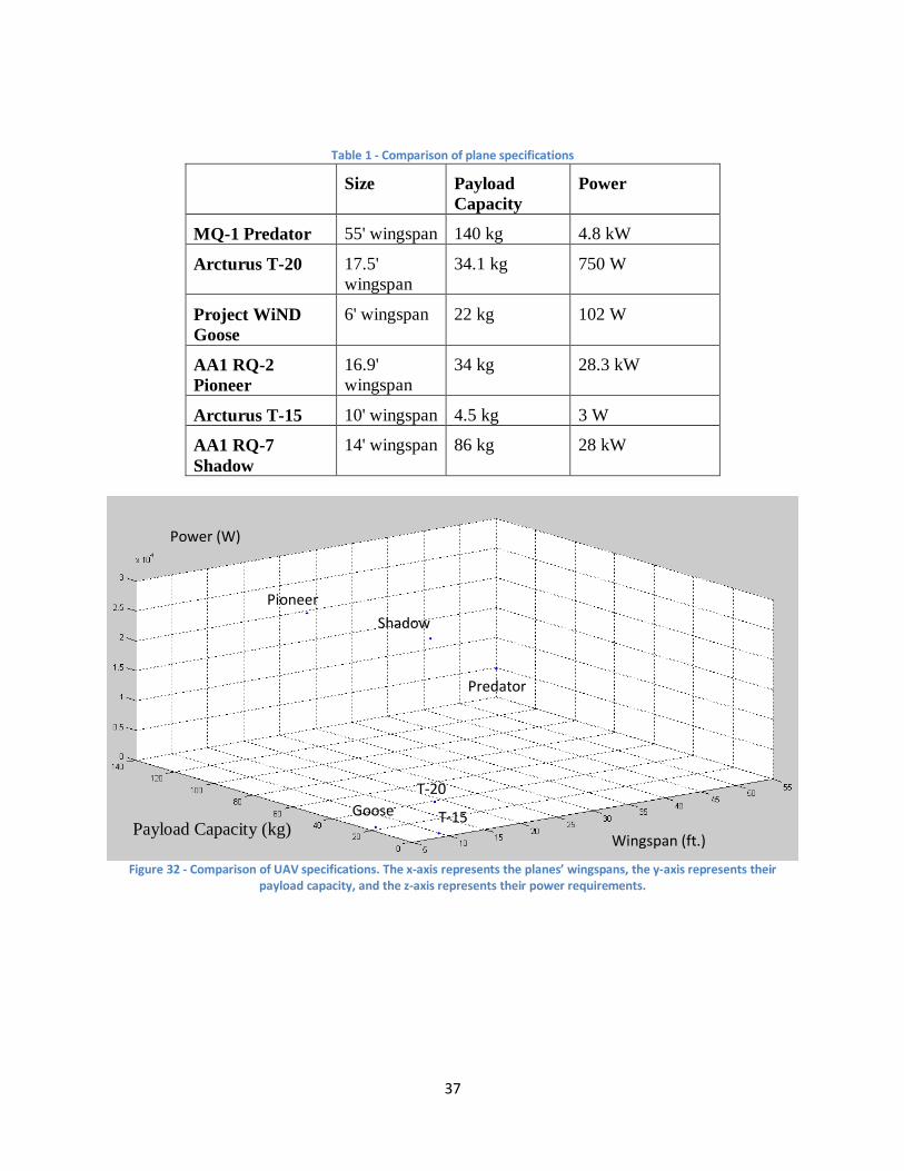
37
Table 1 - Comparison of plane specifications
Size Payload
Capacity
Power
MQ-1 Predator 55' wingspan 140 kg 4.8 kW
Arcturus T-20 17.5'
wingspan
34.1 kg 750 W
Project WiND
Goose
6' wingspan 22 kg 102 W
AA1 RQ-2
Pioneer
16.9'
wingspan
34 kg 28.3 kW
Arcturus T-15 10' wingspan 4.5 kg 3 W
AA1 RQ-7
Shadow
14' wingspan 86 kg 28 kW
Figure 32 - Comparison of UAV specifications. The x-axis represents the planes’ wingspans, the y-axis represents their
payload capacity, and the z-axis represents their power requirements.
Power (W)
Payload Capacity (kg)
Wingspan (ft.)
Goose
T-20
Predator
T-15
Shadow
Pioneer
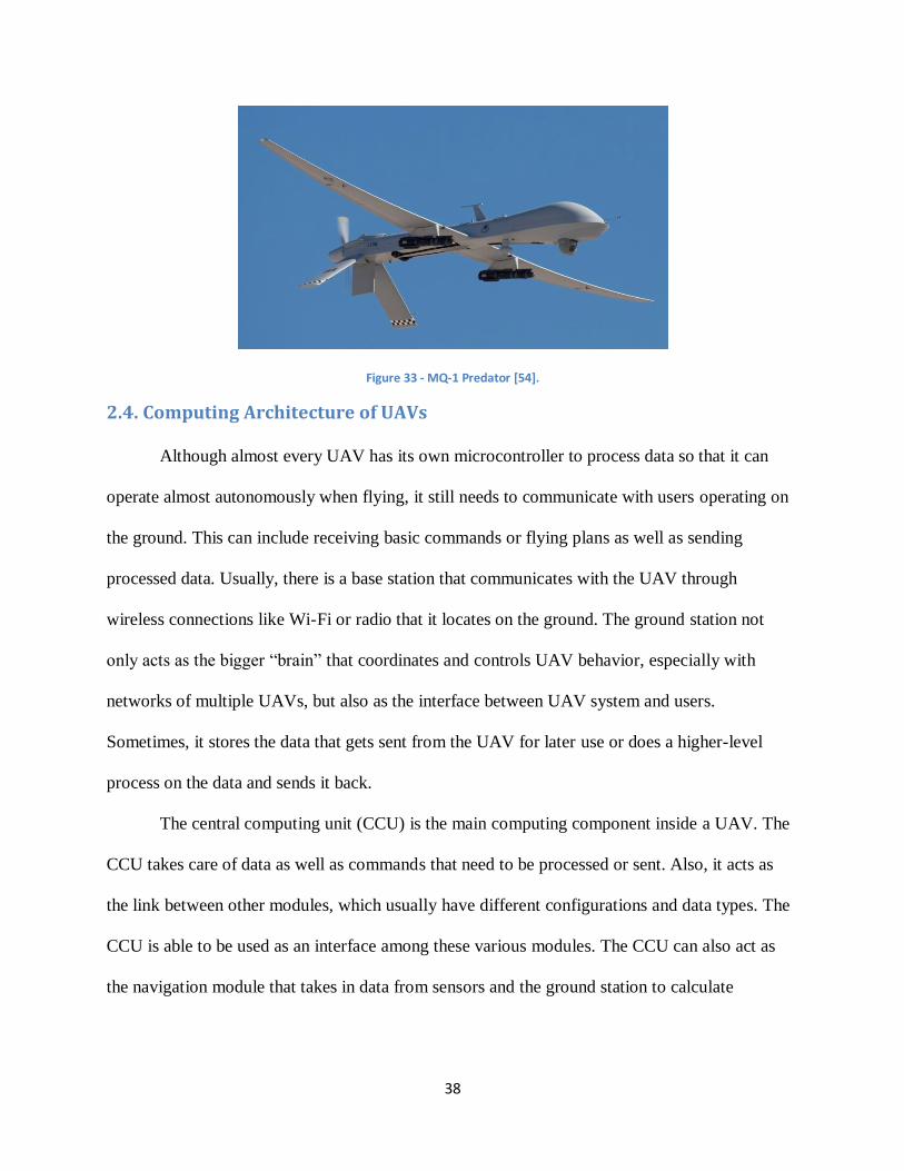
38
Figure 33 - MQ-1 Predator [54].
2.4. Computing Architecture of UAVs
Although almost every UAV has its own microcontroller to process data so that it can
operate almost autonomously when flying, it still needs to communicate with users operating on
the ground. This can include receiving basic commands or flying plans as well as sending
processed data. Usually, there is a base station that communicates with the UAV through
wireless connections like Wi-Fi or radio that it locates on the ground. The ground station not
only acts as the bigger “brain” that coordinates and controls UAV behavior, especially with
networks of multiple UAVs, but also as the interface between UAV system and users.
Sometimes, it stores the data that gets sent from the UAV for later use or does a higher-level
process on the data and sends it back.
The central computing unit (CCU) is the main computing component inside a UAV. The
CCU takes care of data as well as commands that need to be processed or sent. Also, it acts as
the link between other modules, which usually have different configurations and data types. The
CCU is able to be used as an interface among these various modules. The CCU can also act as
the navigation module that takes in data from sensors and the ground station to calculate
39
positions in space and plan a future path based on basic commands from the ground station. It
contains a path planning algorithm that calculates suitable instructions for the autopilot module.
Most UAV platforms contain some sort of image processing module. This normally takes
in images from a camera or other sensor and processes the data to detect relevant information
that can be used by the crew on the ground. This processing can be done on a variety of
computers such as field programmable gate arrays, microprocessors, or digital signal processors.
Usually the computer is programmed with an algorithm that can process distortions in the
background and can tell if that blob is relevant to the task being done. This processed image is
then transmitted to the ground control station where it can be viewed by the people in control of
the operation and they can respond appropriately.
Cameras are a very important part of UAV platforms. Common camera types are linear,
infrared, color, and stereo. These are normally attached to the plane’s payload and capture raw
video that is inputted into a computer module that processes the image. The best camera type to
use depends on the intended application of the mission. Cameras are available in both analog and
digital options and can be converted into different formats via computers either inside the camera
or on a separate module. Other important characteristics to consider when deciding is the field of
vision, weight, power requirements, and desired resolution.
The autopilot module provides the tools for autonomous flight of UAVs. They normally
are equipped with various sensors such as pressure sensors, attitude sensors, and accelerometers.
All of these are essential to flying the plane as they allow it to fly at a steady level and rate to
prevent crashing. Autopilot modules are also equipped with global positioning systems that can
be fed waypoints from a navigation system to perform autonomous flight. The GPS also provides
the users on the ground with location coordinates and velocity that is used to pinpoint the area of
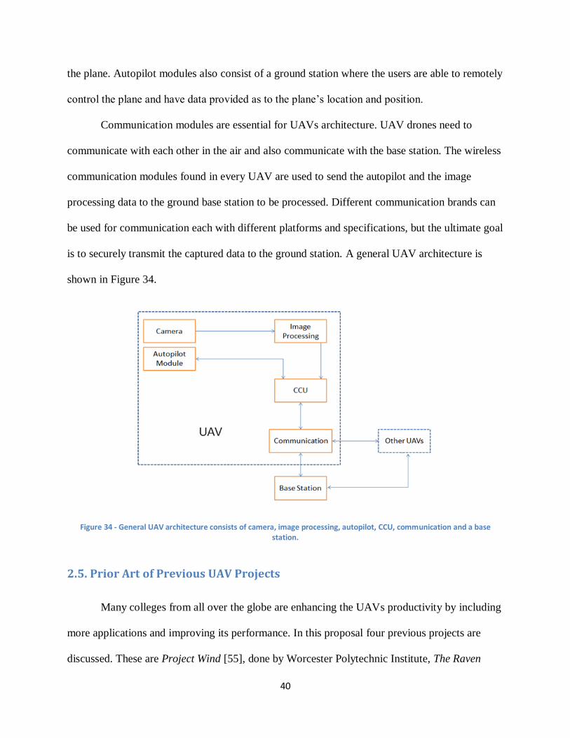
40
the plane. Autopilot modules also consist of a ground station where the users are able to remotely
control the plane and have data provided as to the plane’s location and position.
Communication modules are essential for UAVs architecture. UAV drones need to
communicate with each other in the air and also communicate with the base station. The wireless
communication modules found in every UAV are used to send the autopilot and the image
processing data to the ground base station to be processed. Different communication brands can
be used for communication each with different platforms and specifications, but the ultimate goal
is to securely transmit the captured data to the ground station. A general UAV architecture is
shown in Figure 34.
Figure 34 - General UAV architecture consists of camera, image processing, autopilot, CCU, communication and a base station.
2.5. Prior Art of Previous UAV Projects
Many colleges from all over the globe are enhancing the UAVs productivity by including
more applications and improving its performance. In this proposal four previous projects are
discussed. These are Project Wind [55], done by Worcester Polytechnic Institute, The Raven
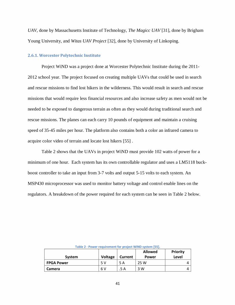
41
UAV, done by Massachusetts Institute of Technology, The Magicc UAV [31], done by Brigham
Young University, and Witas UAV Project [32], done by University of Linkoping.
2.6.1. Worcester Polytechnic Institute
Project WiND was a project done at Worcester Polytechnic Institute during the 2011-
2012 school year. The project focused on creating multiple UAVs that could be used in search
and rescue missions to find lost hikers in the wilderness. This would result in search and rescue
missions that would require less financial resources and also increase safety as men would not be
needed to be exposed to dangerous terrain as often as they would during traditional search and
rescue missions. The planes can each carry 10 pounds of equipment and maintain a cruising
speed of 35-45 miles per hour. The platform also contains both a color an infrared camera to
acquire color video of terrain and locate lost hikers [55] .
Table 2 shows that the UAVs in project WiND must provide 102 watts of power for a
minimum of one hour. Each system has its own controllable regulator and uses a LM5118 buck-
boost controller to take an input from 3-7 volts and output 5-15 volts to each system. An
MSP430 microprocessor was used to monitor battery voltage and control enable lines on the
regulators. A breakdown of the power required for each system can be seen in Table 2 below.
Table 2 - Power requirement for project WiND system [55].
System Voltage Current Allowed Power
Priority Level
FPGA Power 5 V 5 A 25 W 4
Camera 6 V .5 A 3 W 4
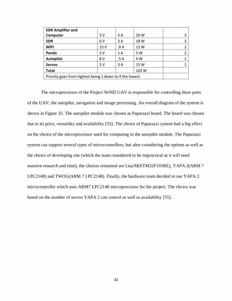
42
SDR Amplifier and Computer 5 V 4 A 20 W 3
SDR 6 V 3 A 18 W 3
WIFI 15 V .8 A 12 W 2
Panda 5 V 1 A 5 W 2
Autopilot 8 V .5 A 4 W 1
Servos 5 V 3 A 15 W 1
Total
102 W Priority goes from highest being 1 down to 4 the lowest
The microprocessor of the Project WiND UAV is responsible for controlling three parts
of the UAV, the autopilot, navigation and image processing. An overall diagram of the system is
shown in Figure 35. The autopilot module was chosen as Paparazzi board. The board was chosen
due to its price, versatility and availability [55]. The choice of Paparazzi system had a big effect
on the choice of the microprocessor used for computing in the autopilot module. The Paparazzi
system can support several types of microcontrollers, but after considering the options as well as
the choice of developing one (which the team considered to be impractical as it will need
massive research and time), the choices remained are Lisa/M(STM32F103RE), YAPA 2(ARM 7
LPC2148) and TWOG(ARM 7 LPC2148). Finally, the hardware team decided to use YAPA 2
microcontroller which uses ARM7 LPC2148 microprocessor for the project. The choice was
based on the number of servos YAPA 2 can control as well as availability [55].
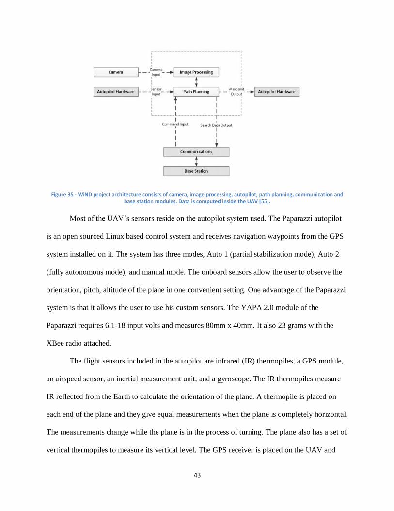
43
Figure 35 - WiND project architecture consists of camera, image processing, autopilot, path planning, communication and base station modules. Data is computed inside the UAV [55].
Most of the UAV’s sensors reside on the autopilot system used. The Paparazzi autopilot
is an open sourced Linux based control system and receives navigation waypoints from the GPS
system installed on it. The system has three modes, Auto 1 (partial stabilization mode), Auto 2
(fully autonomous mode), and manual mode. The onboard sensors allow the user to observe the
orientation, pitch, altitude of the plane in one convenient setting. One advantage of the Paparazzi
system is that it allows the user to use his custom sensors. The YAPA 2.0 module of the
Paparazzi requires 6.1-18 input volts and measures 80mm x 40mm. It also 23 grams with the
XBee radio attached.
The flight sensors included in the autopilot are infrared (IR) thermopiles, a GPS module,
an airspeed sensor, an inertial measurement unit, and a gyroscope. The IR thermopiles measure
IR reflected from the Earth to calculate the orientation of the plane. A thermopile is placed on
each end of the plane and they give equal measurements when the plane is completely horizontal.
The measurements change while the plane is in the process of turning. The plane also has a set of
vertical thermopiles to measure its vertical level. The GPS receiver is placed on the UAV and
44
receives the plane’s position from satellites. This also allows it to calculate the velocity of the
plane but experiences difficulty in windy conditions. The inertial measurement unit contains a
combination of accelerometers and gyroscopes and measures the plane’s acceleration rates and
changes in roll, yaw, and pitch. The time is maintained by an internal processor and the
processor calculates the velocity, position, and orientation of the UAV. This unit is combined
with a khalman filter to compensate for error in location calculation. A separate gyroscope
measures changes in location, pitch, roll, and yaw. It also helps with thermopile stabilization
[29].
The main concerns about the navigation module are power efficiency, price, and being
able to run on Linux OS. Using those standards, the team had chosen the Pandaboard as the main
computing unit for the navigation module and it used the OMAP 4430 processor. With a 1.2
GHz Dual Core ARM processor and enhanced HD-capable media acceleration, Pandaboard had
many advantages over other considered boards.
The parameters of the image processing module were similar with that of the navigation
modules’ as they both concerned receiving data from sensors and processing. The major choices
were selected based on cost, availability, processing power as well as I/O methods. Finally, LX 9
board that use Xilinx Spartan-6 processor was chosen as it provided enough I/O methods as well
as processing power while remaining at a reasonable price [55].
2.6.2. Massachusetts Institute of Technology
The RAVEN UAV project was completed at Massachusetts Institute of Technology in
2007. This project has a similar goal to that of Project WiND done at Worcester Polytechnic
Institute. It involves capturing images and processing them. It differs however as the main goal
of the project is for Health Management and the environment it target is indoors. The platform
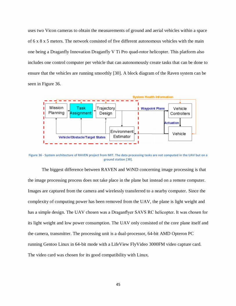
45
uses two Vicon cameras to obtain the measurements of ground and aerial vehicles within a space
of 6 x 8 x 5 meters. The network consisted of five different autonomous vehicles with the main
one being a Draganfly Innovation Draganfly V Ti Pro quad-rotor helicopter. This platform also
includes one control computer per vehicle that can autonomously create tasks that can be done to
ensure that the vehicles are running smoothly [30]. A block diagram of the Raven system can be
seen in Figure 36.
Figure 36 - System architecture of RAVEN project from MIT. The data processing tasks are not computed in the UAV but on a ground station [30].
The biggest difference between RAVEN and WiND concerning image processing is that
the image processing process does not take place in the plane but instead on a remote computer.
Images are captured from the camera and wirelessly transferred to a nearby computer. Since the
complexity of computing power has been removed from the UAV, the plane is light weight and
has a simple design. The UAV chosen was a Draganflyer SAVS RC helicopter. It was chosen for
its light weight and low power consumption. The UAV only consisted of the core plane itself and
the camera, transmitter. The processing unit is a dual-processor, 64-bit AMD Opteron PC
running Gentoo Linux in 64-bit mode with a LifeView FlyVideo 3000FM video capture card.
The video card was chosen for its good compatibility with Linux.
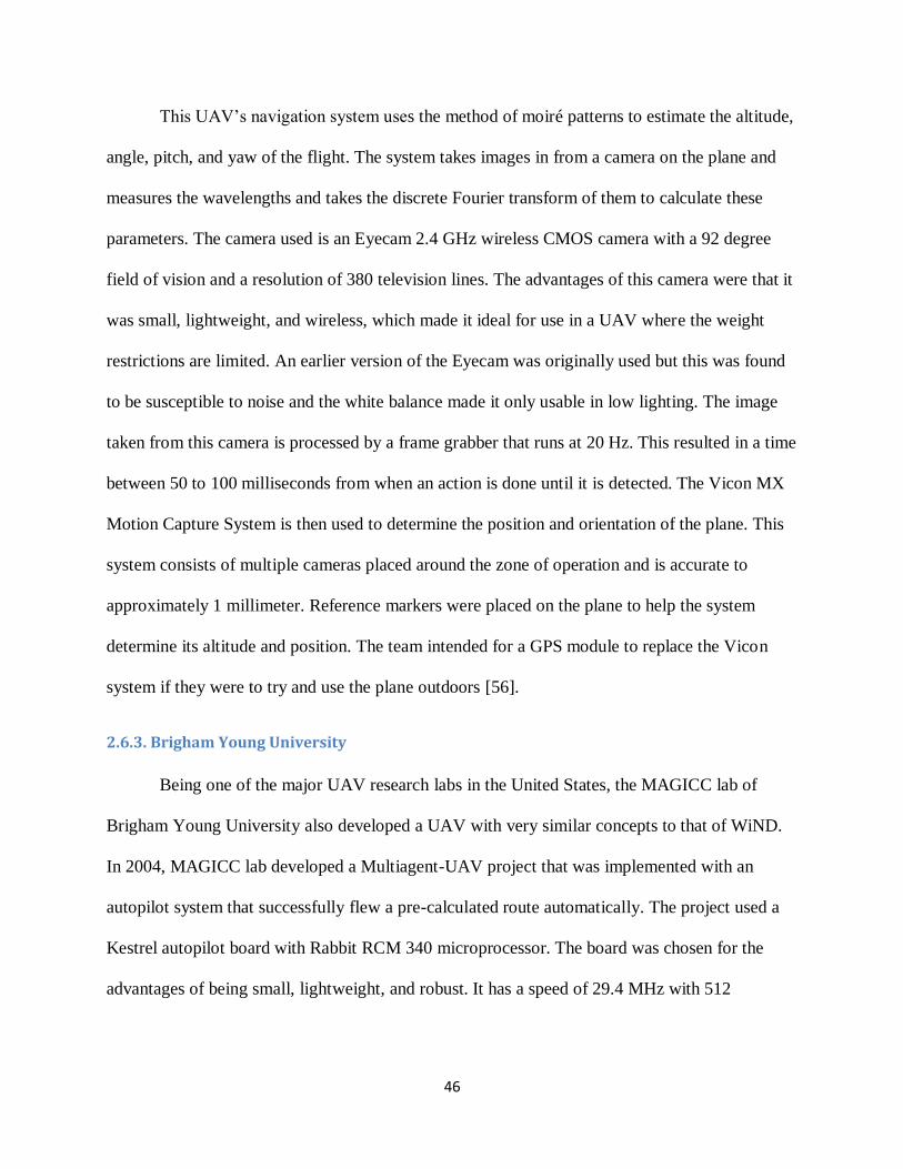
46
This UAV’s navigation system uses the method of moiré patterns to estimate the altitude,
angle, pitch, and yaw of the flight. The system takes images in from a camera on the plane and
measures the wavelengths and takes the discrete Fourier transform of them to calculate these
parameters. The camera used is an Eyecam 2.4 GHz wireless CMOS camera with a 92 degree
field of vision and a resolution of 380 television lines. The advantages of this camera were that it
was small, lightweight, and wireless, which made it ideal for use in a UAV where the weight
restrictions are limited. An earlier version of the Eyecam was originally used but this was found
to be susceptible to noise and the white balance made it only usable in low lighting. The image
taken from this camera is processed by a frame grabber that runs at 20 Hz. This resulted in a time
between 50 to 100 milliseconds from when an action is done until it is detected. The Vicon MX
Motion Capture System is then used to determine the position and orientation of the plane. This
system consists of multiple cameras placed around the zone of operation and is accurate to
approximately 1 millimeter. Reference markers were placed on the plane to help the system
determine its altitude and position. The team intended for a GPS module to replace the Vicon
system if they were to try and use the plane outdoors [56].
2.6.3. Brigham Young University
Being one of the major UAV research labs in the United States, the MAGICC lab of
Brigham Young University also developed a UAV with very similar concepts to that of WiND.
In 2004, MAGICC lab developed a Multiagent-UAV project that was implemented with an
autopilot system that successfully flew a pre-calculated route automatically. The project used a
Kestrel autopilot board with Rabbit RCM 340 microprocessor. The board was chosen for the
advantages of being small, lightweight, and robust. It has a speed of 29.4 MHz with 512
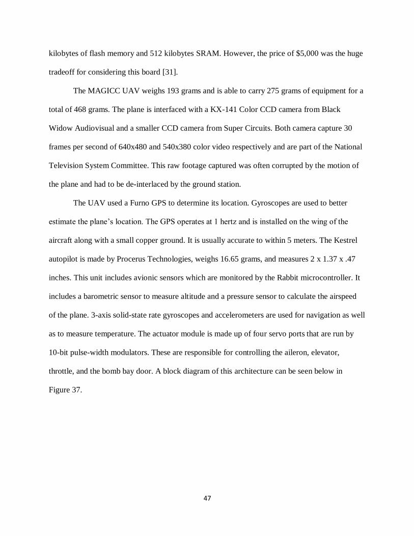
47
kilobytes of flash memory and 512 kilobytes SRAM. However, the price of $5,000 was the huge
tradeoff for considering this board [31].
The MAGICC UAV weighs 193 grams and is able to carry 275 grams of equipment for a
total of 468 grams. The plane is interfaced with a KX-141 Color CCD camera from Black
Widow Audiovisual and a smaller CCD camera from Super Circuits. Both camera capture 30
frames per second of 640x480 and 540x380 color video respectively and are part of the National
Television System Committee. This raw footage captured was often corrupted by the motion of
the plane and had to be de-interlaced by the ground station.
The UAV used a Furno GPS to determine its location. Gyroscopes are used to better
estimate the plane’s location. The GPS operates at 1 hertz and is installed on the wing of the
aircraft along with a small copper ground. It is usually accurate to within 5 meters. The Kestrel
autopilot is made by Procerus Technologies, weighs 16.65 grams, and measures 2 x 1.37 x .47
inches. This unit includes avionic sensors which are monitored by the Rabbit microcontroller. It
includes a barometric sensor to measure altitude and a pressure sensor to calculate the airspeed
of the plane. 3-axis solid-state rate gyroscopes and accelerometers are used for navigation as well
as to measure temperature. The actuator module is made up of four servo ports that are run by
10-bit pulse-width modulators. These are responsible for controlling the aileron, elevator,
throttle, and the bomb bay door. A block diagram of this architecture can be seen below in
Figure 37.
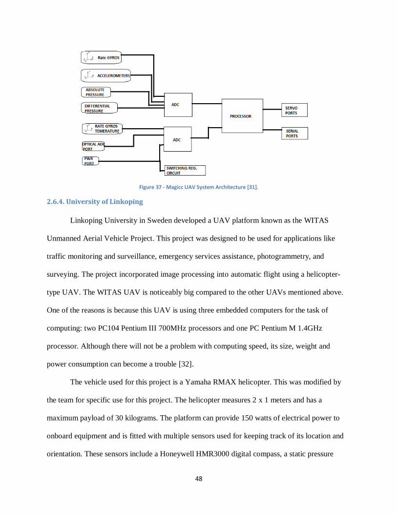
48
Figure 37 - Magicc UAV System Architecture [31].
2.6.4. University of Linkoping
Linkoping University in Sweden developed a UAV platform known as the WITAS
Unmanned Aerial Vehicle Project. This project was designed to be used for applications like
traffic monitoring and surveillance, emergency services assistance, photogrammetry, and
surveying. The project incorporated image processing into automatic flight using a helicopter-
type UAV. The WITAS UAV is noticeably big compared to the other UAVs mentioned above.
One of the reasons is because this UAV is using three embedded computers for the task of
computing: two PC104 Pentium III 700MHz processors and one PC Pentium M 1.4GHz
processor. Although there will not be a problem with computing speed, its size, weight and
power consumption can become a trouble [32].
The vehicle used for this project is a Yamaha RMAX helicopter. This was modified by
the team for specific use for this project. The helicopter measures 2 x 1 meters and has a
maximum payload of 30 kilograms. The platform can provide 150 watts of electrical power to
onboard equipment and is fitted with multiple sensors used for keeping track of its location and
orientation. These sensors include a Honeywell HMR3000 digital compass, a static pressure
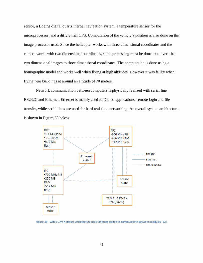
49
sensor, a Boeing digital quartz inertial navigation system, a temperature sensor for the
microprocessor, and a differential GPS. Computation of the vehicle’s position is also done on the
image processor used. Since the helicopter works with three dimensional coordinates and the
camera works with two dimensional coordinates, some processing must be done to convert the
two dimensional images to three dimensional coordinates. The computation is done using a
homographic model and works well when flying at high altitudes. However it was faulty when
flying near buildings at around an altitude of 70 meters.
Network communication between computers is physically realized with serial line
RS232C and Ethernet. Ethernet is mainly used for Corba applications, remote login and file
transfer, while serial lines are used for hard real-time networking. An overall system architecture
is shown in Figure 38 below.
Figure 38 - Witas UAV Network Architecture uses Ethernet switch to communicate between modules [32].
50
Corba (Common Object Request Broker Architecture) is often used as middleware for
object-based distributed systems. It enables different objects or components to communicate with
each other regardless of the programming languages in which they are written and their location
on different processors or the operating systems are they running on. A component can act as a
client, a server or as both.
The Bluetooth Wireless Serial Port adapter (RS232) is the ideal serial cable replacement.
It can be used to connect serial printers, serial scanners, or any other device to a computer or
remote up to over 300 feet (100 meters) away. This wireless serial port does not require a
computer to function. After it is configured, it can simply be plugged in and it is ready to work.
The RS232 can be used with PDAs, computers, laptops, and smartphones that support the
Bluetooth Serial Port Profile and Bluetooth Generic Access Profile. As such, this wireless serial
port adapter is ideal for use in applications where a PDA or laptop would communicate with
another device (SBC, RTU, sensor, robot, radio, PBX) wirelessly.
2.6. Current Security of Unmanned Aerial Vehicle Technology
In the past and even now, when people used keys and locks to protect luxuries, money or
important data, there was always a risk of lock picking or key stealing. In order to counter those
ill-intended approaches, people have to create new security methods or enhance old ones. Since
this is a digital era, and Internet has become an enormous library that can grant almost any
information of its users, security’s role in network structure is emphasized more than ever.
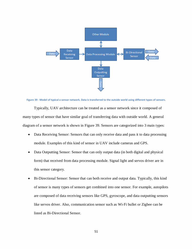
51
Figure 39 - Model of typical a sensor network. Data is transferred to the outside world using different types of sensors.
Typically, UAV architecture can be treated as a sensor network since it composed of
many types of sensor that have similar goal of transferring data with outside world. A general
diagram of a sensor network is shown in Figure 39. Sensors are categorized into 3 main types:
Data Receiving Sensor: Sensors that can only receive data and pass it to data processing
module. Examples of this kind of sensor in UAV include cameras and GPS.
Data Outputting Sensor: Sensor that can only output data (in both digital and physical
form) that received from data processing module. Signal light and servos driver are in
this sensor category.
Bi-Directional Sensor: Sensor that can both receive and output data. Typically, this kind
of sensor is many types of sensors get combined into one sensor. For example, autopilots
are composed of data receiving sensors like GPS, gyroscope, and data outputting sensors
like servos driver. Also, communication sensor such as Wi-Fi bullet or Zigbee can be
listed as Bi-Directional Sensor.
52
Also, there is data link between local modules inside the system. However, since those
data links are usually physically connected (wires, PCB), they can only be attacked physically.
As UAVs operate in midair, attacking the system physically (in the sense of data) would be
impractical. Thus, attacks would focus on the three types of sensors listed above. For example,
the data receiving sensor could be attacked with feeding false data, possibly causing unexpected
behavior. For data outputting Sensor, the attack could be “eavesdropping” on outputted data.
Preventing data transmitting process, jamming, is also a typical type of attack in sensor network.
Of course, any type of attack that could be used in other two sensor types can also be applied to
bi-directional sensors.
Using the same logic, securing a sensor network should focus on the data being
transferred among the sensors. For example, one famous type of security technique is encryption,
aimed at defending the network against “eavesdropping” attack. In encryption, original data is
altered in a fashion in which only the authorized system could recognize the data and vice versa.
This ensures that unauthorized personnel cannot make any use of data even if they can capture
the transferred information. Another example of security enhancing technique is implementing
the system with an intelligent algorithm that can differentiate between true and false signal, thus
protecting the data receiving sensor.
2.7. Chapter Summary
The concept of UAVs has been around for nearly one hundred years. They originally
started out and remained a military tool for many decades but have since evolved to be used for
many various applications. Today UAVs are still a big part of the military but are also used for
civil tasks such as traffic monitoring and search and rescue missions. UAVs architecture also
differs greatly. There are many different computing options and architectures available in the
53
market and all of them have their own sets of advantages and disadvantages. The designer of a
specific platform must pick a computer and architecture based on the task at hand and the
constraints that he or she has to work with. The market for UAVs has grown dramatically over
the past decade with most of it being in the United States and Israel. Many European countries
are also adopting these tools for their own applications. With all of the data stored on these
machines, security is crucial. Users of UAVs need to be assured that the data stored on these
machines will be protected from malicious attacks that could jeopardize the status of the mission
or the authenticity of the data. UAV use has grown dramatically over the past few decades and it
is increasing as time goes on.
54
3. Proposed Approach
This chapter covers the proposed approach for this project. In here the various options for
system architectures are described and compared as well as the individual components and
methods used. Components are chosen for the power, wireless communications, image
processing, video capture, and autopilot systems of the final design. From a high-level approach,
the system works by capturing video with the camera, looking for a blob of certain color on the
central computing unit, reading the coordinates of where the platform is from the autopilot, and
transmitting that data to the ground control laptop where it can be read by the controlling user.
3.1. Computing Options
This section describes the options available for the architecture and components of this
project. Each option has different pros and cons, and has various effects on different
applications. Thus, the choices made must be those components which best meet the project’s
objectives.
3.1.1. Design Architectures
The goal of this project is to develop a computer system that can be used in any UAV.
Thus, although there are many types of UAV architectures with some having complex designs
that can boost efficiency, this system should be as close to a basic design of UAV system as
possible. The most basic components are camera, image processing, autopilot, central
computing unit, communication, and base station. Since this platform will only focus on
transferring data between the UAV and base station, the communication module is only
composed of Wi-Fi bullets. Since this project is focused on data security between UAVs and
base station, there should be a module for that purpose and it should be located before the Wi-Fi
bullet. Furthermore, since the autopilot module is a separated package, it cannot be combined
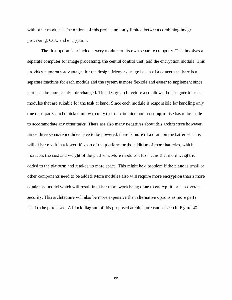
55
with other modules. The options of this project are only limited between combining image
processing, CCU and encryption.
The first option is to include every module on its own separate computer. This involves a
separate computer for image processing, the central control unit, and the encryption module. This
provides numerous advantages for the design. Memory usage is less of a concern as there is a
separate machine for each module and the system is more flexible and easier to implement since
parts can be more easily interchanged. This design architecture also allows the designer to select
modules that are suitable for the task at hand. Since each module is responsible for handling only
one task, parts can be picked out with only that task in mind and no compromise has to be made
to accommodate any other tasks. There are also many negatives about this architecture however.
Since three separate modules have to be powered, there is more of a drain on the batteries. This
will either result in a lower lifespan of the platform or the addition of more batteries, which
increases the cost and weight of the platform. More modules also means that more weight is
added to the platform and it takes up more space. This might be a problem if the plane is small or
other components need to be added. More modules also will require more encryption than a more
condensed model which will result in either more work being done to encrypt it, or less overall
security. This architecture will also be more expensive than alternative options as more parts
need to be purchased. A block diagram of this proposed architecture can be seen in Figure 40.
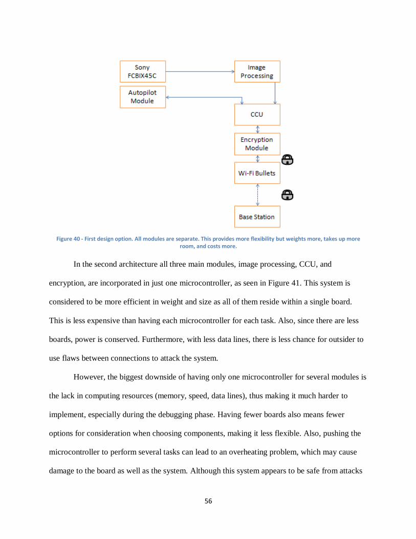
56
Figure 40 - First design option. All modules are separate. This provides more flexibility but weights more, takes up more
room, and costs more.
In the second architecture all three main modules, image processing, CCU, and
encryption, are incorporated in just one microcontroller, as seen in Figure 41. This system is
considered to be more efficient in weight and size as all of them reside within a single board.
This is less expensive than having each microcontroller for each task. Also, since there are less
boards, power is conserved. Furthermore, with less data lines, there is less chance for outsider to
use flaws between connections to attack the system.
However, the biggest downside of having only one microcontroller for several modules is
the lack in computing resources (memory, speed, data lines), thus making it much harder to
implement, especially during the debugging phase. Having fewer boards also means fewer
options for consideration when choosing components, making it less flexible. Also, pushing the
microcontroller to perform several tasks can lead to an overheating problem, which may cause
damage to the board as well as the system. Although this system appears to be safe from attacks
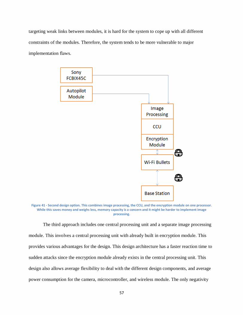
57
targeting weak links between modules, it is hard for the system to cope up with all different
constraints of the modules. Therefore, the system tends to be more vulnerable to major
implementation flaws.
Figure 41 - Second design option. This combines image processing, the CCU, and the encryption module on one processor.
While this saves money and weighs less, memory capacity is a concern and it might be harder to implement image processing.
The third approach includes one central processing unit and a separate image processing
module. This involves a central processing unit with already built in encryption module. This
provides various advantages for the design. This design architecture has a faster reaction time to
sudden attacks since the encryption module already exists in the central processing unit. This
design also allows average flexibility to deal with the different design components, and average
power consumption for the camera, microcontroller, and wireless module. The only negativity
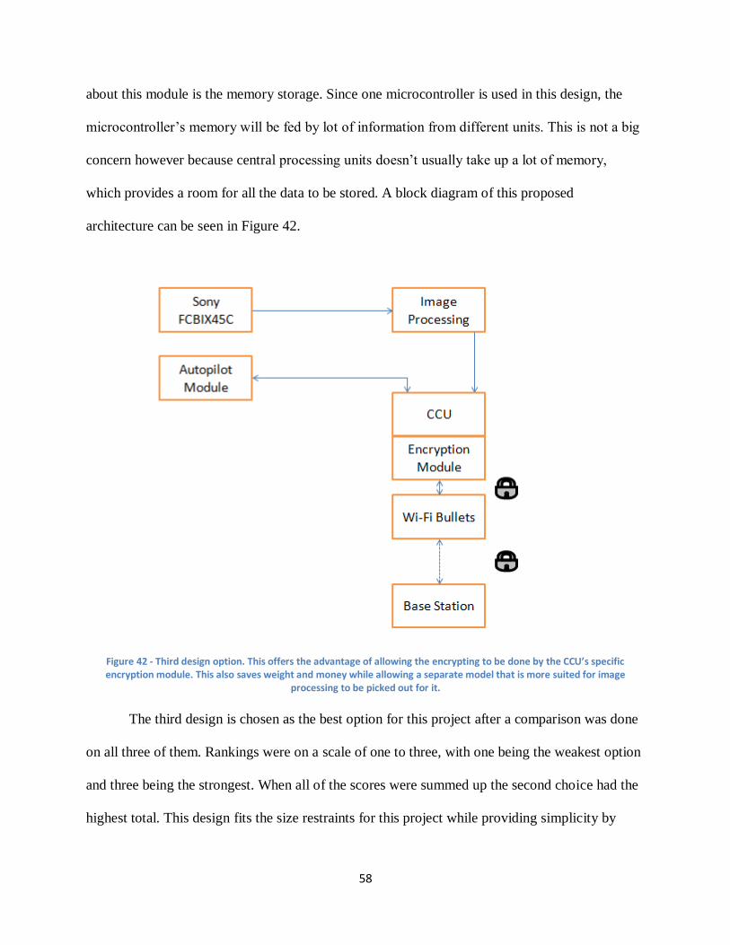
58
about this module is the memory storage. Since one microcontroller is used in this design, the
microcontroller’s memory will be fed by lot of information from different units. This is not a big
concern however because central processing units doesn’t usually take up a lot of memory,
which provides a room for all the data to be stored. A block diagram of this proposed
architecture can be seen in Figure 42.
Figure 42 - Third design option. This offers the advantage of allowing the encrypting to be done by the CCU’s specific encryption module. This also saves weight and money while allowing a separate model that is more suited for image
processing to be picked out for it.
The third design is chosen as the best option for this project after a comparison was done
on all three of them. Rankings were on a scale of one to three, with one being the weakest option
and three being the strongest. When all of the scores were summed up the second choice had the
highest total. This design fits the size restraints for this project while providing simplicity by
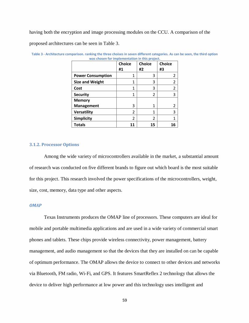
59
having both the encryption and image processing modules on the CCU. A comparison of the
proposed architectures can be seen in Table 3.
Table 3 - Architecture comparison. ranking the three choises in seven different categories. As can be seen, the third option was chosen for implementation in this project.
Choice #1
Choice #2
Choice #3
Power Consumption 1 3 2
Size and Weight 1 3 2
Cost 1 3 2
Security 1 2 3
Memory Management 3 1 2
Versatility 2 1 3
Simplicity 2 2 1
Totals 11 15 16
3.1.2. Processor Options
Among the wide variety of microcontrollers available in the market, a substantial amount
of research was conducted on five different brands to figure out which board is the most suitable
for this project. This research involved the power specifications of the microcontrollers, weight,
size, cost, memory, data type and other aspects.
OMAP
Texas Instruments produces the OMAP line of processors. These computers are ideal for
mobile and portable multimedia applications and are used in a wide variety of commercial smart
phones and tablets. These chips provide wireless connectivity, power management, battery
management, and audio management so that the devices that they are installed on can be capable
of optimum performance. The OMAP allows the device to connect to other devices and networks
via Bluetooth, FM radio, Wi-Fi, and GPS. It features SmartReflex 2 technology that allows the
device to deliver high performance at low power and this technology uses intelligent and
60
adaptive silicon, circuit design, and software to allow the board to function at low power. The
audio management system also allows it to connect to numerous devices including head-sets,
speakers, vibrators, amplifiers, and microphones [57].
Texas Instruments also provides a software suite that makes programming the OMAP
processor easier. The system supports most high-level languages including Symbia, Microsoft
Windows CE, Java, Palm, and Linux [58]. The suite includes mobile operating system drivers,
solutions to connect to GPS, Bluetooth, FM, and Wi-Fi, and system-level power management.
The platform also supports the use of multiple operating systems running on the same platform
simultaneously [59].
One of the OMAP’s best qualities is that it can deliver high resolution 1080p video. It is
enabled for 3D graphics and 20 megapixel imaging. The board runs on two ARM Cortex-A9
processors capable of speeds up to 1 GHz. The graphics are controlled by a POWERVR SGX540
graphics accelerator. There are also IVA 3 hardware accelerators that enable the high definition
video and allow it to be encoded and decoded. The chip supports HDMI output. A block diagram
can be seen in Figure 43 below [59].
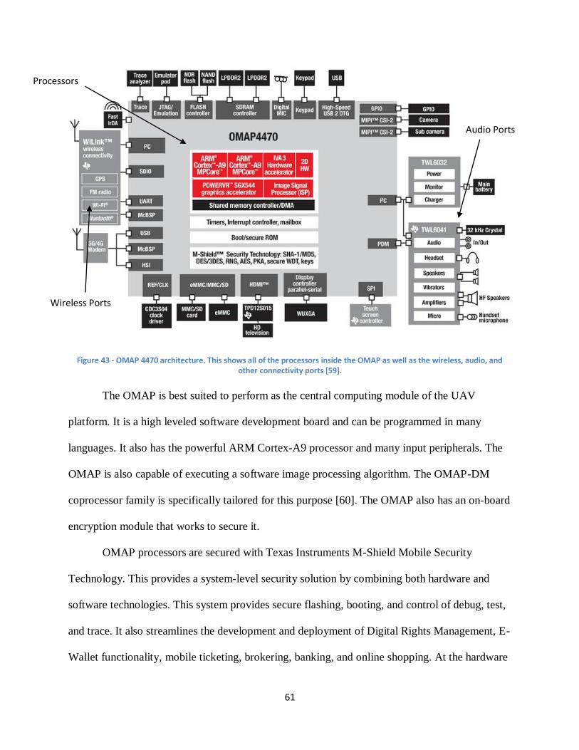
61
Figure 43 - OMAP 4470 architecture. This shows all of the processors inside the OMAP as well as the wireless, audio, and other connectivity ports [59].
The OMAP is best suited to perform as the central computing module of the UAV
platform. It is a high leveled software development board and can be programmed in many
languages. It also has the powerful ARM Cortex-A9 processor and many input peripherals. The
OMAP is also capable of executing a software image processing algorithm. The OMAP-DM
coprocessor family is specifically tailored for this purpose [60]. The OMAP also has an on-board
encryption module that works to secure it.
OMAP processors are secured with Texas Instruments M-Shield Mobile Security
Technology. This provides a system-level security solution by combining both hardware and
software technologies. This system provides secure flashing, booting, and control of debug, test,
and trace. It also streamlines the development and deployment of Digital Rights Management, E-
Wallet functionality, mobile ticketing, brokering, banking, and online shopping. At the hardware
Audio Ports
Processors
Wireless Ports
62
level the security provided includes hardware cryptographic accelerators and random number
generators, public key infrastructure with secure on-chip keys, and protections against malicious
software attacks. It also encrypts the memory on the system by providing a secure state machine
and secure RAM and ROM. The software level is on top of the hardware level and provides
secure signing and flashing tools, toolkits for creating unique secure signatures for applications,
and security packs to make the HLOS security stronger. The software technology also has a
Security Middleware Component that allows software to be used on different platform
generations [61].
MSP430
The MSP430 platform of microprocessors put out by Texas Instruments are low-power
affordable options for many computing needs. The component is a RISC 16-bit mixed-signal
microprocessor. The central processing unit uses the von Neumann architecture which means
that the program and data memory are located in a single space and bytes are stored in little
Endean. The processor has sixteen sixteen-bit registers. Four of the bits are saved for special
functions and the rest of them can be written to or read from. There are over 400 different
MSP430 microcontrollers, each with their own specific specifications.
The most recent generation of MSP430 microcontrollers is the 6 series. These operate on
1.8 volts and are as fast as 25 MHz. When only 1.8 volts are being used to power it however it
can only be as fast as 12 MHz. The devices require very low power to operate however and they
only need one microamp of current for RAM retention and two and a half microamps to stay in
real-time clock mode. It only needs 165 microamps per million instructions per second (MIPS)
to be in active mode. It also only requires less than five microseconds to wake up from Standby
63
Mode [62]. The controller features up to 256 kilobytes of Flash Memory and 18 kilobytes of
random access memory (RAM).
The system features three analog devices, an analog to digital converter (ADC), a
comparator, and a digital to analog converter (DAC). The ADC can be used to convert an analog
input voltage to a twelve bit binary number and the DAC can be used to do the opposite. The
comparator simply compares two input voltages and determines which one is higher. They also
feature both an internal and external temperature sensor.
The microcontrollers also feature multiple sixteen-bit timers as well as a watchdog timer
that can reset the system in the event of a malfunction. There are also up to seventy-four general
purpose input/output pins that can be configured to either take in or output data. It also includes
other serial interfaces such as UART, SPI, I2C, SPI, and USB. It also features an LCD display
that can be used to display multiple seven segment numbers. A block diagram of the system
architecture is shown in Figure 44.
The MSP430 can be programmed using C or assembly language. The RISC computer
contains 27 instructions in three different families. While C allows for easier and simpler
programming assembly uses much less memory and is faster. A block diagram of the
MSP430F6438 of the 6 series family can be seen below. This architecture is similar to the all 6
series product.
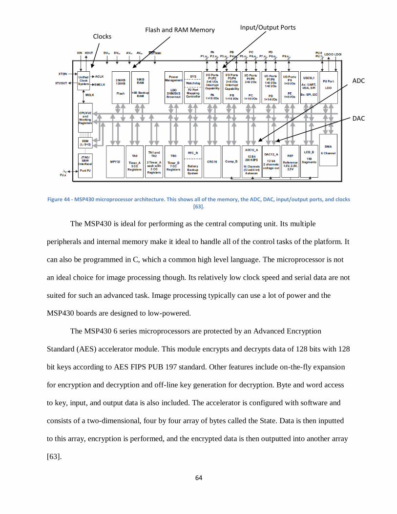
64
Figure 44 - MSP430 microprocessor architecture. This shows all of the memory, the ADC, DAC, input/output ports, and clocks [63].
The MSP430 is ideal for performing as the central computing unit. Its multiple
peripherals and internal memory make it ideal to handle all of the control tasks of the platform. It
can also be programmed in C, which a common high level language. The microprocessor is not
an ideal choice for image processing though. Its relatively low clock speed and serial data are not
suited for such an advanced task. Image processing typically can use a lot of power and the
MSP430 boards are designed to low-powered.
The MSP430 6 series microprocessors are protected by an Advanced Encryption
Standard (AES) accelerator module. This module encrypts and decrypts data of 128 bits with 128
bit keys according to AES FIPS PUB 197 standard. Other features include on-the-fly expansion
for encryption and decryption and off-line key generation for decryption. Byte and word access
to key, input, and output data is also included. The accelerator is configured with software and
consists of a two-dimensional, four by four array of bytes called the State. Data is then inputted
to this array, encryption is performed, and the encrypted data is then outputted into another array
[63].
Clocks Flash and RAM Memory Input/Output Ports
ADC
DAC
65
Digital Signal Processors
Digital signal processors (DSPs) are microcontrollers designed for the fast operational
needs of a digital signal processing. Unlike regular microprocessors which are general purpose
central processing units, DSPs are specialized processing units. DSPs are used for embedded
devices applications including medical images, digital communication, speech recognition, radar,
and many other applications. They are used in all kind of handheld computers, large mainframes,
and supercomputers.
Most general-purpose microprocessors and operating systems can execute DSP
algorithms successfully, but are not suitable for use in portable devices such as mobile phones
and personal digital assistants because of power supply and space constraints. A specialized
digital signal processor, however, will tend to provide a lower-cost solution, with better
performance, lower latency, and no requirements for specialized cooling or large batteries.
DSPs’ hardware usually include a hardware modulo addressing for circular buffers, a
memory architecture for streaming data, separate program and data memories, special single
instruction multiple data operations, special arithmetic operations, special addressing modes, and
a memory management unit. Its program flow includes a floating point unit, pipelined
architecture parallel multiplier accumulator and its memory architecture includes special
architectures that are able to obtain multiple data instructions at the same time. A general DSP
block diagram is shown in Figure 45.
TMS320C64XX is an example of a modern DSP family produced by Texas Instruments.
The TI TMS320C64XX optimizes and maximizes the power efficiency and battery life of
portable and mobile applications. The TMS320C64XX can handle real time processing, which
means that they give the optimal performance even when they are streaming data. This processor
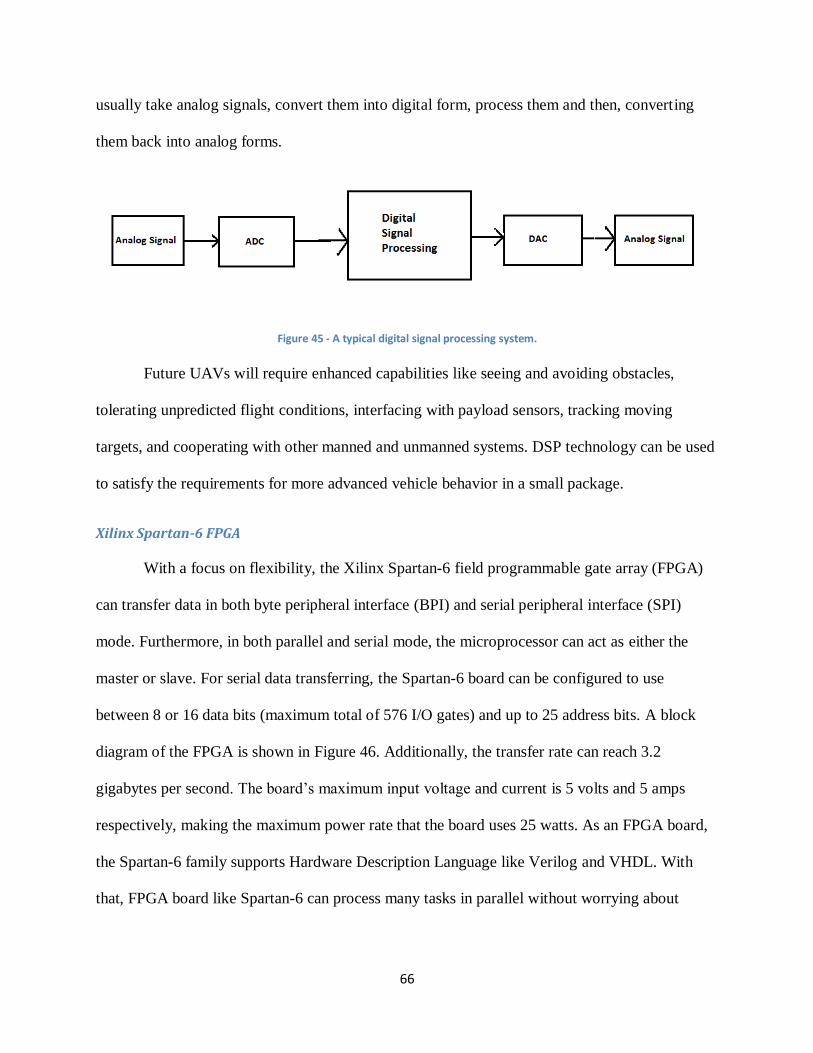
66
usually take analog signals, convert them into digital form, process them and then, converting
them back into analog forms.
Figure 45 - A typical digital signal processing system.
Future UAVs will require enhanced capabilities like seeing and avoiding obstacles,
tolerating unpredicted flight conditions, interfacing with payload sensors, tracking moving
targets, and cooperating with other manned and unmanned systems. DSP technology can be used
to satisfy the requirements for more advanced vehicle behavior in a small package.
Xilinx Spartan-6 FPGA
With a focus on flexibility, the Xilinx Spartan-6 field programmable gate array (FPGA)
can transfer data in both byte peripheral interface (BPI) and serial peripheral interface (SPI)
mode. Furthermore, in both parallel and serial mode, the microprocessor can act as either the
master or slave. For serial data transferring, the Spartan-6 board can be configured to use
between 8 or 16 data bits (maximum total of 576 I/O gates) and up to 25 address bits. A block
diagram of the FPGA is shown in Figure 46. Additionally, the transfer rate can reach 3.2
gigabytes per second. The board’s maximum input voltage and current is 5 volts and 5 amps
respectively, making the maximum power rate that the board uses 25 watts. As an FPGA board,
the Spartan-6 family supports Hardware Description Language like Verilog and VHDL. With
that, FPGA board like Spartan-6 can process many tasks in parallel without worrying about
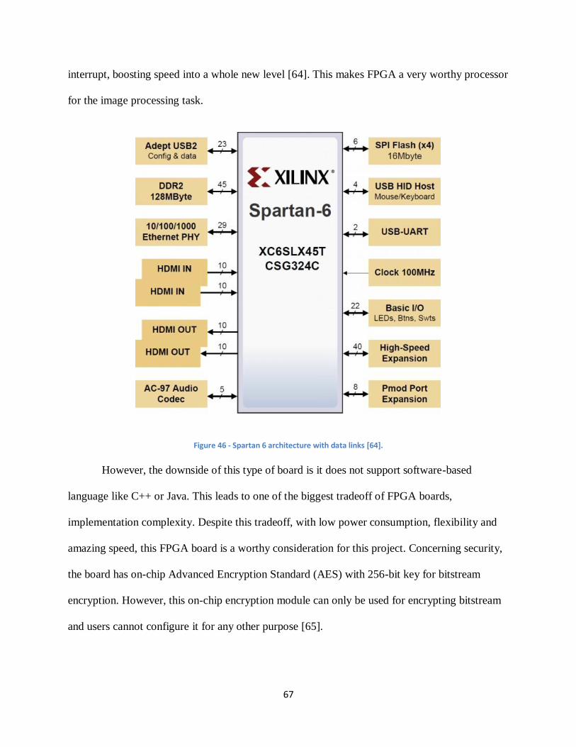
67
interrupt, boosting speed into a whole new level [64]. This makes FPGA a very worthy processor
for the image processing task.
Figure 46 - Spartan 6 architecture with data links [64].
However, the downside of this type of board is it does not support software-based
language like C++ or Java. This leads to one of the biggest tradeoff of FPGA boards,
implementation complexity. Despite this tradeoff, with low power consumption, flexibility and
amazing speed, this FPGA board is a worthy consideration for this project. Concerning security,
the board has on-chip Advanced Encryption Standard (AES) with 256-bit key for bitstream
encryption. However, this on-chip encryption module can only be used for encrypting bitstream
and users cannot configure it for any other purpose [65].
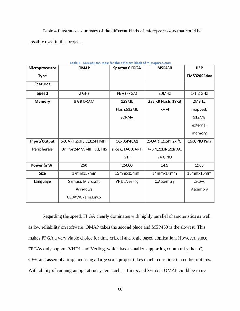
68
Table 4 illustrates a summary of the different kinds of microprocessors that could be
possibly used in this project.
Table 4 - Comparison table for the different kinds of microporcessors
Microprocessor
Type
OMAP Spartan 6 FPGA MSP430 DSP
TMS320C64xx
Features
Speed 2 GHz N/A (FPGA) 20MHz 1-1.2 GHz
Memory 8 GB DRAM 128Mb
Flash,512Mb
SDRAM
256 KB Flash, 18KB
RAM
2MB L2
mapped,
512MB
external
memory
Input/Output
Peripherals
5xUART,2xHSIC,3xSPI,MIPI
UniPortSMM,MIPI LLI, HIS
16xDSP48A1
slices,JTAG,UART,
GTP
2xUART,2xSPI,2xI2C,
4xSPI,2xLIN,2xIrDA,
74 GPIO
16xGPIO Pins
Power (mW) 250 25000 14.9 1900
Size 17mmx17mm 15mmx15mm 14mmx14mm 16mmx16mm
Language Symbia, Microsoft
Windows
CE,JAVA,Palm,Linux
VHDL,Verilog C,Assembly C/C++,
Assembly
Regarding the speed, FPGA clearly dominates with highly parallel characteristics as well
as low reliability on software. OMAP takes the second place and MSP430 is the slowest. This
makes FPGA a very viable choice for time critical and logic based application. However, since
FPGAs only support VHDL and Verilog, which has a smaller supporting community than C,
C++, and assembly, implementing a large scale project takes much more time than other options.
With ability of running an operating system such as Linux and Symbia, OMAP could be more
69
suitably used for a central computing role as it could use compatible drivers to communicate
with other hardware. MSP430 would be too slow for resource heavy applications. While feasible
as a computing unit since it has decent speed, the lacking of running an operating system made
DSP less suitable for the central unit.
3.1.3. Processing Tasks
In this system, each module requires implementation in both hardware and software for
its specific task. The exception to this is the autopilot module, which has its own software and
hardware package. This section discusses which options were considered for this system.
Image Processing
The image processing module is a very important part of this project. This part of the
UAV platform will be responsible for taking in input video from the camera module and running
an algorithm on it to detect items of interest. There are many existing programs available for this
task and they come in a variety of packages. This algorithm can be implemented in either
hardware or software and each method has its own advantages. Software can be programmed in a
higher level language such as C or Java and it is generally easier to implement. This processing
is normally done on central processing units (CPUs) when programmed in software. CPUs have
the advantage of having a higher frequency than other devices. The CPUs discussed in this paper
are the MSP430, OMAP, and TMSC600 [66] [67].
Algorithms in hardware are typically programmed on FPGAs. This is done in a Hardware
Description Language such as VHSIC Hardware Description Language (VHDL) or Verilog [67].
While FPGAs tend to have lower clock speeds than CPUs they hold the advantage of being able
to process parallel data, while CPUs typically are only able to process serially. FPGAs’ clocks
normally operate in the order of hundreds of MHz while CPUs clocks can operate at one to two
70
GHz. However, FPGAs can carry out up to tens of thousands of instructions per clock cycle
while CPUs can only perform about four to eight instructions per clock cycle. [67]. This
parallelism in FPGAs makes them quicker and more power efficient than FPGAs. The FPGA
considered for this project is the Spartan-6.
For this project the image processing algorithm is implemented on the Beagleboard CPU,
running on an OMAP processor. While FPGAs provide many performance advantages over
CPUs for image processing algorithms, the algorithms can be more easily implemented in
software. The computer vision library, OpenCV, contains many off the shelf algorithms that can
be used and modified to fit the needs of this project. Using the Beagleboard is also more
convenient because it comes with a dedicated camera port that can be used to input images to the
CPU. Using other options would have required either the use of an intermediary decoder board
or to write code to convert the images into a suitable format to be processed. Since writing an
image processing algorithm is not the main goal of this project it was decided that the
Beagleboard would be used to process images.
To decide what specifications are needed for the component running the algorithm, the
Lena picture is used as a benchmark. The Lena image was originally used in an image processing
experiment at the University of California in 1973 and has been used as a benchmark for image
processing algorithms since then [68]. The image is shown in Figure 47. This image has a size of
512x512 and is of the RGB data type [68]. Since three bytes of data are used for RGB, the
memory needed for this algorithm can be figured by multiplying 512, 512, and 3 for a data size
of 786,432 bytes or 786.432 kilobytes. The Beagleboard-xM fits this need by providing 512
megabytes of LPDDR RAM and 4 megabytes of memory on an external security data card.

71
Figure 47 - Lena. This is the image that algorithms normally use to test their effectiveness against [68].
Central Computing Unit
In order for the UAV to act autonomously with minimal human command, it needs a
module to process and determine how it needs to behave. This task is usually done with a central
computing unit module. This module acts as the “brain” of whole UAV system. Its purpose is to
decide which behavior it should do based on the processed data. The CCU also acts as medium
between other modules and the base station. This means it receives data from other modules and
stores, processes, or sends useful data to the base station and vice versa. There are several
algorithms can be used to serve as artificial intelligence for UAVs. Since this project’s scope
does not include developing algorithms for the CCU and the system is only composed of few
sensors, the main task for the CCU to just transfer data between modules and decide what to send
to the base station.
The hardware choices considered for this module were the Beagleboard which uses the
OMAP processor and LX 9 Microboard that use Spartan-6 FPGA. After a selection process,
Beagleboard was chosen for the system processor based on its low power requirements, small
size and weight, and high performance.
72
3.2. Framework Architecture
This UAV platform includes seven main parts: a camera, autopilot module, image
processing module, a central control unit, an encryption module, a communications module, and
a base station. These are responsible for capturing data, storing and encrypting it, and checking it
to see if there is relevant data in it. The autopilot is responsible for allowing the plane to fly at
the correct level and transmitting data to the ground station regarding the plane’s coordinates and
position data. The central control unit is responsible for controlling the plane itself and transmits
relevant data down to the user controlling the plane on the ground. It is responsible for detecting
attacks and also includes the encryption module responsible for encrypting and protecting data.
The communication module is responsible for transmitting data between the plane and ground
station and the base station is responsible for controlling the plane and receiving data from it.
A Leopard Imaging LI-LBCM3MI camera is used to capture raw images from the area
below the plane. The camera is connected directly to the CCU and be processed directly on the
board. The video sent is of type YUV format. The image processing algorithm will search for
potential targets in the video using the OpenCV image library and transmit the coordinates of
that target to the ground control station via Wi-Fi.
The autopilot module is responsible for flying the plane and receiving the global
positioning coordinates. An ArduPilot autopilot component is used to these tasks. The altitude,
longitude, and latitude is outputted in Mavlink, outputted to the CCU, converted to ASCII, and
transferred to the base station via Wi-Fi. The ArduPilot is connected to the CCU via universal
serial bus (USB) cord.
The central control unit consists of a Beagleboard development board. This is responsible
for processing and sending all of the data from the autopilot and image processing algorithm to
73
the communication module and encrypting the data. The module is responsible for detecting
attacks on the plane and changing the path of the plane accordingly as well as other core
functions. The Texas Instruments (TI) OMAP processor on the Beagleboard is equipped with TI
M-Shield Mobile Security Technology. This module supports encryption of data through both
hardware and software and is used to encrypt the data that passes through the CCU.
Wi-Fi is used for the communication method for this UAV platform. Ubiquiti Wi-Fi
bullets are placed on the UAV as well as the ground station. The data from the CCU is
transmitted to the bullets with an Ethernet cord and is transmitted to the base station through a
2.4 GHz radio frequency signal to the base station. The base station will consist of a laptop
running the image processing algorithm and receives all of the data from the image processing
and autopilot modules.
The framework architecture of the UAV platform consists of a camera, autopilot, CCU,
encryption, communication, and base station module. These parts hold different responsibilities
that are essential to the completion of tasks for the UAV. The platform consists of two parts, the
part responsible for the on-board data and the ground station where the user will be controlling
the module. A detailed diagram of the architecture can be seen in Figure 48 below.
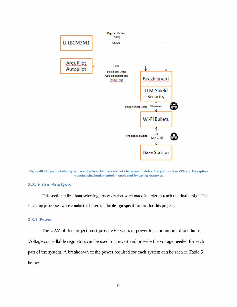
74
Figure 48 - Project detailed system architecture that has data links between modules. The platform has CCU and Encryption module being implemented in one board for saving resources.
3.3. Value Analysis
This section talks about selecting processes that were made in order to reach the final design. The
selecting processes were conducted based on the design specifications for this project.
3.3.1. Power
The UAV of this project must provide 67 watts of power for a minimum of one hour.
Voltage controllable regulators can be used to convert and provide the voltage needed for each
part of the system. A breakdown of the power required for each system can be seen in Table 5
below.
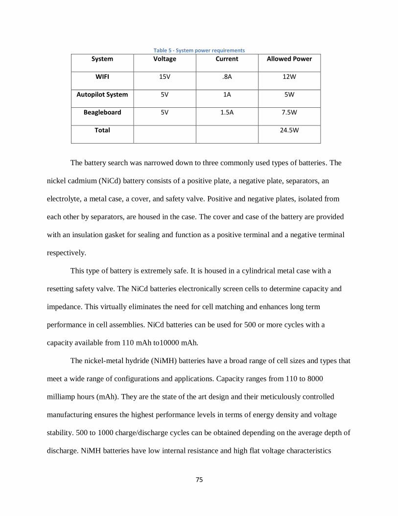
75
Table 5 - System power requirements
System Voltage Current Allowed Power
WIFI 15V .8A 12W
Autopilot System 5V 1A 5W
Beagleboard 5V 1.5A 7.5W
Total 24.5W
The battery search was narrowed down to three commonly used types of batteries. The
nickel cadmium (NiCd) battery consists of a positive plate, a negative plate, separators, an
electrolyte, a metal case, a cover, and safety valve. Positive and negative plates, isolated from
each other by separators, are housed in the case. The cover and case of the battery are provided
with an insulation gasket for sealing and function as a positive terminal and a negative terminal
respectively.
This type of battery is extremely safe. It is housed in a cylindrical metal case with a
resetting safety valve. The NiCd batteries electronically screen cells to determine capacity and
impedance. This virtually eliminates the need for cell matching and enhances long term
performance in cell assemblies. NiCd batteries can be used for 500 or more cycles with a
capacity available from 110 mAh to10000 mAh.
The nickel-metal hydride (NiMH) batteries have a broad range of cell sizes and types that
meet a wide range of configurations and applications. Capacity ranges from 110 to 8000
milliamp hours (mAh). They are the state of the art design and their meticulously controlled
manufacturing ensures the highest performance levels in terms of energy density and voltage
stability. 500 to 1000 charge/discharge cycles can be obtained depending on the average depth of
discharge. NiMH batteries have low internal resistance and high flat voltage characteristics
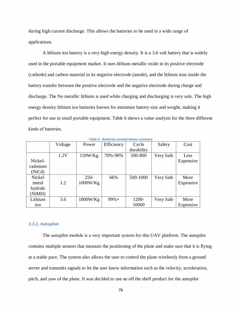
76
during high current discharge. This allows the batteries to be used in a wide range of
applications.
A lithium ion battery is a very high energy density. It is a 3.6 volt battery that is widely
used in the portable equipment market. It uses lithium metallic oxide in its positive electrode
(cathode) and carbon material in its negative electrode (anode), and the lithium ions inside the
battery transfer between the positive electrode and the negative electrode during charge and
discharge. The No metallic lithium is used while charging and discharging is very safe. The high
energy density lithium ion batteries known for minimize battery size and weight, making it
perfect for use in small portable equipment. Table 6 shows a value analysis for the three different
kinds of batteries.
Table 6 - Batteries considerations summary
Voltage Power Efficiency Cycle
durability
Safety Cost
Nickel-
cadmium
(NiCd)
1.2V 150W/Kg 70%-90% 500-800 Very Safe Less
Expensive
Nickel
metal
hydride
(NiMH)
1.2
250-
1000W/Kg
66% 500-1000 Very Safe More
Expensive
Lithium
ion
3.6 1800W/Kg 99%+ 1200-
10000
Very Safe More
Expensive
3.3.2. Autopilot
The autopilot module is a very important system for this UAV platform. The autopilot
contains multiple sensors that measure the positioning of the plane and make sure that it is flying
at a stable pace. The system also allows the user to control the plane wirelessly from a ground
server and transmits signals to let the user know information such as the velocity, acceleration,
pitch, and yaw of the plane. It was decided to use an off the shelf product for the autopilot
77
module seeing as creating a custom one would take much time and effort and is not within the
scope of this project. Four autopilot systems were researched that are specifically designed for
UAVs, Paparazzi, Kestrel, Piccolo, OpenPilot, and ArduPilot.
The Paparazzi autopilot is an open source product that was used in Worcester Polytechnic
Institute’s Project WiND in 2011-2012 and is configured to work with STMicroelectronics
STM32Fxxx microcontroller boards [29]. The important components of the module include the
main autopilot board, sensors, a GPS receiver, datalink radio modem, an RC receiver, servos, a
propulsion system, batteries, and payload. The sensors included depend on the board model that
is bought and they can be added and taken off as needed. The system also includes a ground
control station used to control the aircraft [69]. A block diagram is shown in Figure 49.
The software can be run in Linux or Mac OS X on most notebook computers. The
software includes a graphical user interface (GUI) to control the UAV and a simulator to
simulate flight patterns. It also includes a data logging system and other tools for communicating
with the UAVs [69].
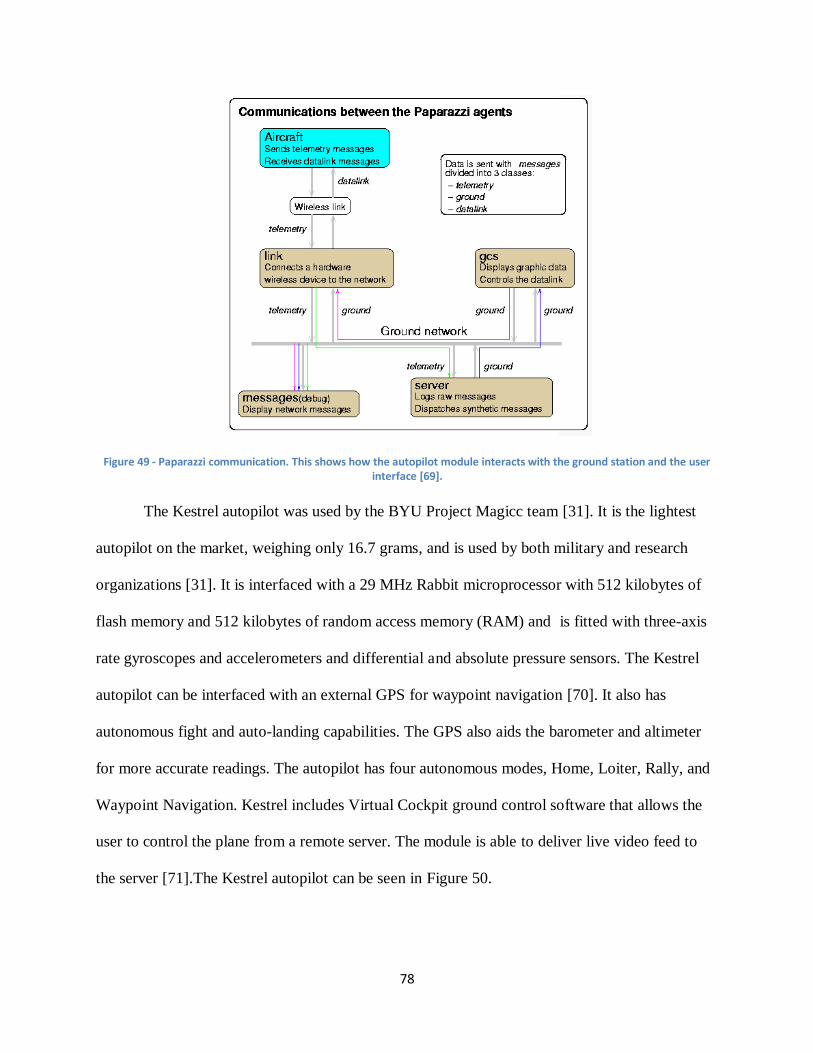
78
Figure 49 - Paparazzi communication. This shows how the autopilot module interacts with the ground station and the user interface [69].
The Kestrel autopilot was used by the BYU Project Magicc team [31]. It is the lightest
autopilot on the market, weighing only 16.7 grams, and is used by both military and research
organizations [31]. It is interfaced with a 29 MHz Rabbit microprocessor with 512 kilobytes of
flash memory and 512 kilobytes of random access memory (RAM) and is fitted with three-axis
rate gyroscopes and accelerometers and differential and absolute pressure sensors. The Kestrel
autopilot can be interfaced with an external GPS for waypoint navigation [70]. It also has
autonomous fight and auto-landing capabilities. The GPS also aids the barometer and altimeter
for more accurate readings. The autopilot has four autonomous modes, Home, Loiter, Rally, and
Waypoint Navigation. Kestrel includes Virtual Cockpit ground control software that allows the
user to control the plane from a remote server. The module is able to deliver live video feed to
the server [71].The Kestrel autopilot can be seen in Figure 50.
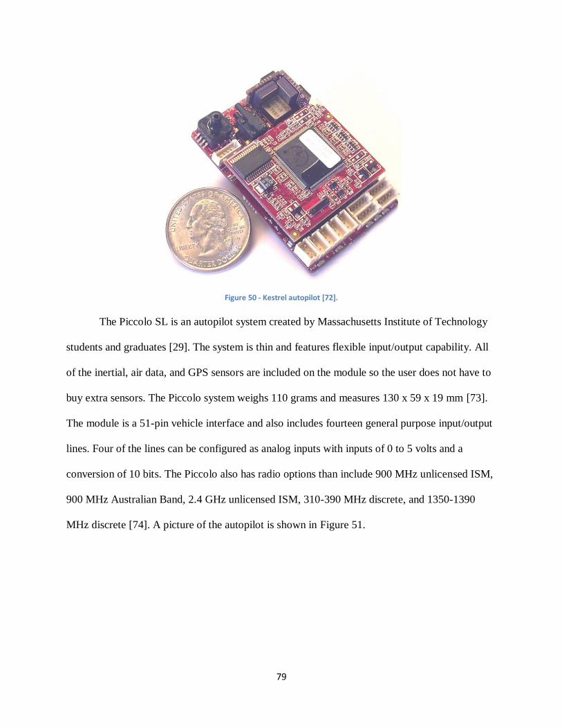
79
Figure 50 - Kestrel autopilot [72].
The Piccolo SL is an autopilot system created by Massachusetts Institute of Technology
students and graduates [29]. The system is thin and features flexible input/output capability. All
of the inertial, air data, and GPS sensors are included on the module so the user does not have to
buy extra sensors. The Piccolo system weighs 110 grams and measures 130 x 59 x 19 mm [73].
The module is a 51-pin vehicle interface and also includes fourteen general purpose input/output
lines. Four of the lines can be configured as analog inputs with inputs of 0 to 5 volts and a
conversion of 10 bits. The Piccolo also has radio options than include 900 MHz unlicensed ISM,
900 MHz Australian Band, 2.4 GHz unlicensed ISM, 310-390 MHz discrete, and 1350-1390
MHz discrete [74]. A picture of the autopilot is shown in Figure 51.
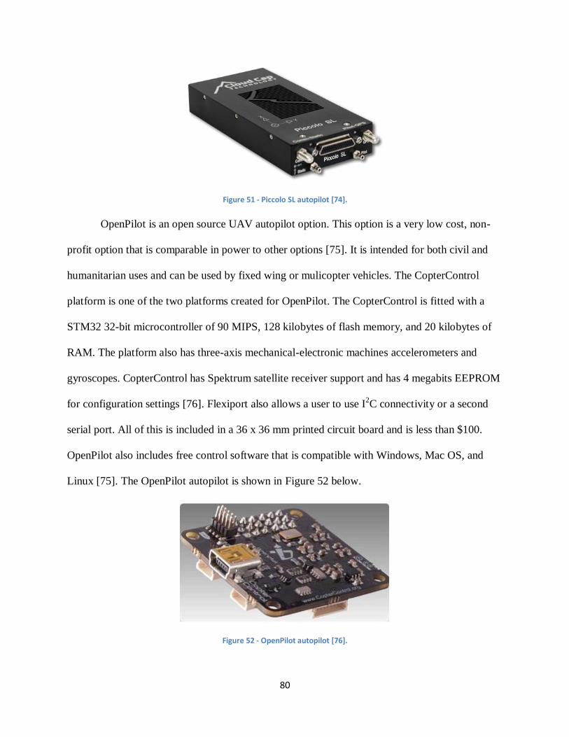
80
Figure 51 - Piccolo SL autopilot [74].
OpenPilot is an open source UAV autopilot option. This option is a very low cost, non-
profit option that is comparable in power to other options [75]. It is intended for both civil and
humanitarian uses and can be used by fixed wing or mulicopter vehicles. The CopterControl
platform is one of the two platforms created for OpenPilot. The CopterControl is fitted with a
STM32 32-bit microcontroller of 90 MIPS, 128 kilobytes of flash memory, and 20 kilobytes of
RAM. The platform also has three-axis mechanical-electronic machines accelerometers and
gyroscopes. CopterControl has Spektrum satellite receiver support and has 4 megabits EEPROM
for configuration settings [76]. Flexiport also allows a user to use I2C connectivity or a second
serial port. All of this is included in a 36 x 36 mm printed circuit board and is less than $100.
OpenPilot also includes free control software that is compatible with Windows, Mac OS, and
Linux [75]. The OpenPilot autopilot is shown in Figure 52 below.
Figure 52 - OpenPilot autopilot [76].
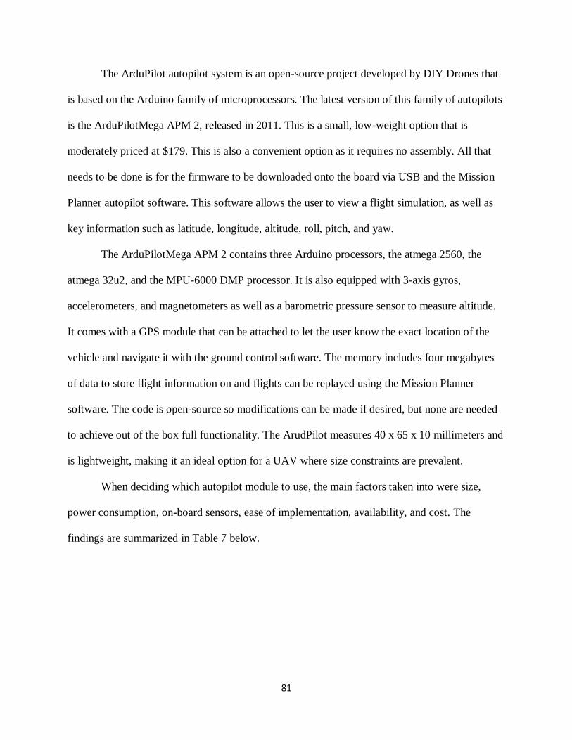
81
The ArduPilot autopilot system is an open-source project developed by DIY Drones that
is based on the Arduino family of microprocessors. The latest version of this family of autopilots
is the ArduPilotMega APM 2, released in 2011. This is a small, low-weight option that is
moderately priced at $179. This is also a convenient option as it requires no assembly. All that
needs to be done is for the firmware to be downloaded onto the board via USB and the Mission
Planner autopilot software. This software allows the user to view a flight simulation, as well as
key information such as latitude, longitude, altitude, roll, pitch, and yaw.
The ArduPilotMega APM 2 contains three Arduino processors, the atmega 2560, the
atmega 32u2, and the MPU-6000 DMP processor. It is also equipped with 3-axis gyros,
accelerometers, and magnetometers as well as a barometric pressure sensor to measure altitude.
It comes with a GPS module that can be attached to let the user know the exact location of the
vehicle and navigate it with the ground control software. The memory includes four megabytes
of data to store flight information on and flights can be replayed using the Mission Planner
software. The code is open-source so modifications can be made if desired, but none are needed
to achieve out of the box full functionality. The ArudPilot measures 40 x 65 x 10 millimeters and
is lightweight, making it an ideal option for a UAV where size constraints are prevalent.
When deciding which autopilot module to use, the main factors taken into were size,
power consumption, on-board sensors, ease of implementation, availability, and cost. The
findings are summarized in Table 7 below.
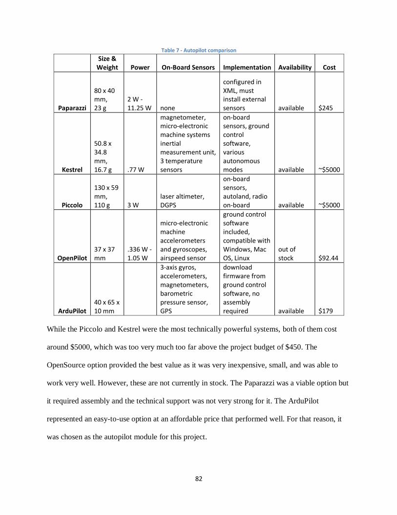
82
Table 7 - Autopilot comparison
Size & Weight Power On-Board Sensors Implementation Availability Cost
Paparazzi
80 x 40 mm, 23 g
2 W - 11.25 W none
configured in XML, must install external sensors available $245
Kestrel
50.8 x 34.8 mm, 16.7 g .77 W
magnetometer, micro-electronic machine systems inertial measurement unit, 3 temperature sensors
on-board sensors, ground control software, various autonomous modes available ~$5000
Piccolo
130 x 59 mm, 110 g 3 W
laser altimeter, DGPS
on-board sensors, autoland, radio on-board available ~$5000
OpenPilot 37 x 37 mm
.336 W - 1.05 W
micro-electronic machine accelerometers and gyroscopes, airspeed sensor
ground control software included, compatible with Windows, Mac OS, Linux
out of stock $92.44
ArduPilot 40 x 65 x 10 mm
3-axis gyros, accelerometers, magnetometers, barometric pressure sensor, GPS
download firmware from ground control software, no assembly required available $179
While the Piccolo and Kestrel were the most technically powerful systems, both of them cost
around $5000, which was too very much too far above the project budget of $450. The
OpenSource option provided the best value as it was very inexpensive, small, and was able to
work very well. However, these are not currently in stock. The Paparazzi was a viable option but
it required assembly and the technical support was not very strong for it. The ArduPilot
represented an easy-to-use option at an affordable price that performed well. For that reason, it
was chosen as the autopilot module for this project.
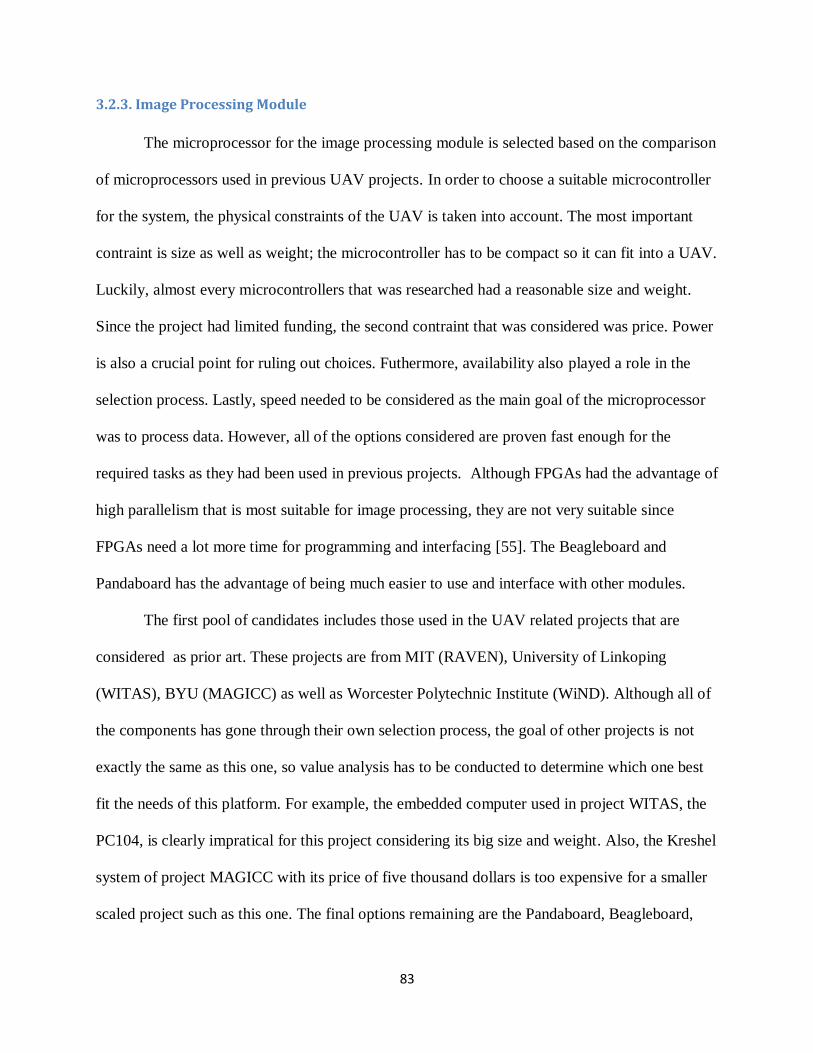
83
3.2.3. Image Processing Module
The microprocessor for the image processing module is selected based on the comparison
of microprocessors used in previous UAV projects. In order to choose a suitable microcontroller
for the system, the physical constraints of the UAV is taken into account. The most important
contraint is size as well as weight; the microcontroller has to be compact so it can fit into a UAV.
Luckily, almost every microcontrollers that was researched had a reasonable size and weight.
Since the project had limited funding, the second contraint that was considered was price. Power
is also a crucial point for ruling out choices. Futhermore, availability also played a role in the
selection process. Lastly, speed needed to be considered as the main goal of the microprocessor
was to process data. However, all of the options considered are proven fast enough for the
required tasks as they had been used in previous projects. Although FPGAs had the advantage of
high parallelism that is most suitable for image processing, they are not very suitable since
FPGAs need a lot more time for programming and interfacing [55]. The Beagleboard and
Pandaboard has the advantage of being much easier to use and interface with other modules.
The first pool of candidates includes those used in the UAV related projects that are
considered as prior art. These projects are from MIT (RAVEN), University of Linkoping
(WITAS), BYU (MAGICC) as well as Worcester Polytechnic Institute (WiND). Although all of
the components has gone through their own selection process, the goal of other projects is not
exactly the same as this one, so value analysis has to be conducted to determine which one best
fit the needs of this platform. For example, the embedded computer used in project WITAS, the
PC104, is clearly impratical for this project considering its big size and weight. Also, the Kreshel
system of project MAGICC with its price of five thousand dollars is too expensive for a smaller
scaled project such as this one. The final options remaining are the Pandaboard, Beagleboard,
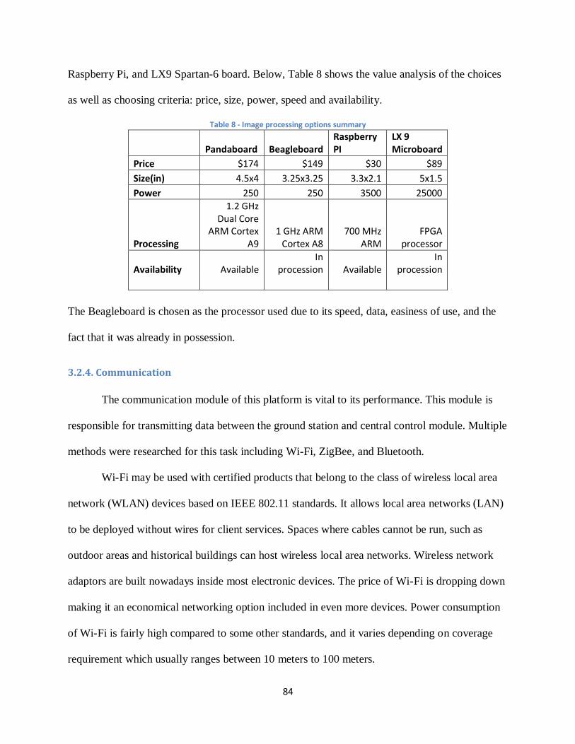
84
Raspberry Pi, and LX9 Spartan-6 board. Below, Table 8 shows the value analysis of the choices
as well as choosing criteria: price, size, power, speed and availability.
Table 8 - Image processing options summary
Pandaboard Beagleboard Raspberry PI
LX 9 Microboard
Price $174 $149 $30 $89
Size(in) 4.5x4 3.25x3.25 3.3x2.1 5x1.5
Power 250 250 3500 25000
Processing
1.2 GHz Dual Core
ARM Cortex A9
1 GHz ARM Cortex A8
700 MHz ARM
FPGA processor
Availability Available In
procession Available In
procession
The Beagleboard is chosen as the processor used due to its speed, data, easiness of use, and the
fact that it was already in possession.
3.2.4. Communication
The communication module of this platform is vital to its performance. This module is
responsible for transmitting data between the ground station and central control module. Multiple
methods were researched for this task including Wi-Fi, ZigBee, and Bluetooth.
Wi-Fi may be used with certified products that belong to the class of wireless local area
network (WLAN) devices based on IEEE 802.11 standards. It allows local area networks (LAN)
to be deployed without wires for client services. Spaces where cables cannot be run, such as
outdoor areas and historical buildings can host wireless local area networks. Wireless network
adaptors are built nowadays inside most electronic devices. The price of Wi-Fi is dropping down
making it an economical networking option included in even more devices. Power consumption
of Wi-Fi is fairly high compared to some other standards, and it varies depending on coverage
requirement which usually ranges between 10 meters to 100 meters.
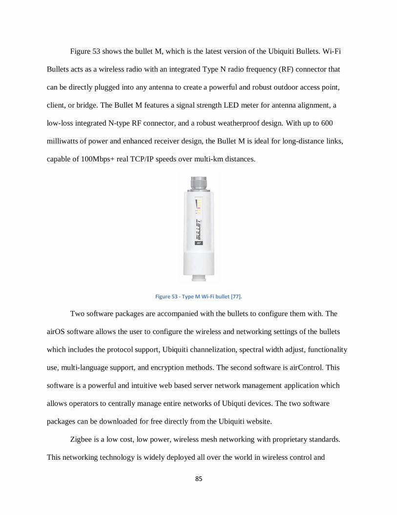
85
Figure 53 shows the bullet M, which is the latest version of the Ubiquiti Bullets. Wi-Fi
Bullets acts as a wireless radio with an integrated Type N radio frequency (RF) connector that
can be directly plugged into any antenna to create a powerful and robust outdoor access point,
client, or bridge. The Bullet M features a signal strength LED meter for antenna alignment, a
low-loss integrated N-type RF connector, and a robust weatherproof design. With up to 600
milliwatts of power and enhanced receiver design, the Bullet M is ideal for long-distance links,
capable of 100Mbps+ real TCP/IP speeds over multi-km distances.
Figure 53 - Type M Wi-Fi bullet [77].
Two software packages are accompanied with the bullets to configure them with. The
airOS software allows the user to configure the wireless and networking settings of the bullets
which includes the protocol support, Ubiquiti channelization, spectral width adjust, functionality
use, multi-language support, and encryption methods. The second software is airControl. This
software is a powerful and intuitive web based server network management application which
allows operators to centrally manage entire networks of Ubiquti devices. The two software
packages can be downloaded for free directly from the Ubiquiti website.
Zigbee is a low cost, low power, wireless mesh networking with proprietary standards.
This networking technology is widely deployed all over the world in wireless control and
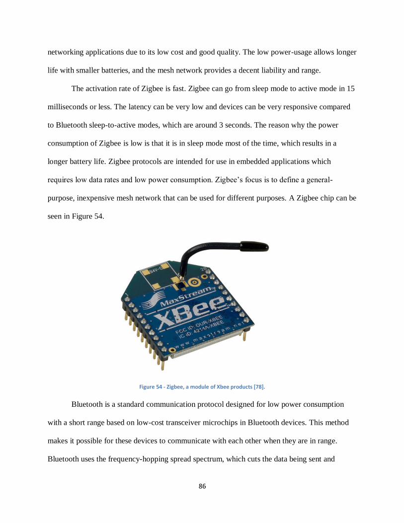
86
networking applications due to its low cost and good quality. The low power-usage allows longer
life with smaller batteries, and the mesh network provides a decent liability and range.
The activation rate of Zigbee is fast. Zigbee can go from sleep mode to active mode in 15
milliseconds or less. The latency can be very low and devices can be very responsive compared
to Bluetooth sleep-to-active modes, which are around 3 seconds. The reason why the power
consumption of Zigbee is low is that it is in sleep mode most of the time, which results in a
longer battery life. Zigbee protocols are intended for use in embedded applications which
requires low data rates and low power consumption. Zigbee’s focus is to define a general-
purpose, inexpensive mesh network that can be used for different purposes. A Zigbee chip can be
seen in Figure 54.
Figure 54 - Zigbee, a module of Xbee products [78].
Bluetooth is a standard communication protocol designed for low power consumption
with a short range based on low-cost transceiver microchips in Bluetooth devices. This method
makes it possible for these devices to communicate with each other when they are in range.
Bluetooth uses the frequency-hopping spread spectrum, which cuts the data being sent and
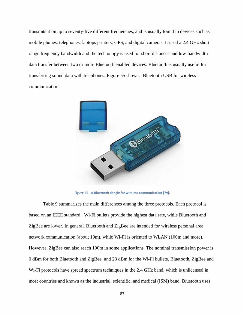
87
transmits it on up to seventy-five different frequencies, and is usually found in devices such as
mobile phones, telephones, laptops printers, GPS, and digital cameras. It used a 2.4 GHz short
range frequency bandwidth and the technology is used for short distances and low-bandwidth
data transfer between two or more Bluetooth enabled devices. Bluetooth is usually useful for
transferring sound data with telephones. Figure 55 shows a Bluetooth USB for wireless
communication.
Figure 55 - A Bluetooth dongle for wireless communication [79].
Table 9 summarizes the main differences among the three protocols. Each protocol is
based on an IEEE standard. Wi-Fi bullets provide the highest data rate, while Bluetooth and
ZigBee are lower. In general, Bluetooth and ZigBee are intended for wireless personal area
network communication (about 10m), while Wi-Fi is oriented to WLAN (100m and more).
However, ZigBee can also reach 100m in some applications. The nominal transmission power is
0 dBm for both Bluetooth and ZigBee, and 28 dBm for the Wi-Fi bullets. Bluetooth, ZigBee and
Wi-Fi protocols have spread spectrum techniques in the 2.4 GHz band, which is unlicensed in
most countries and known as the industrial, scientific, and medical (ISM) band. Bluetooth uses
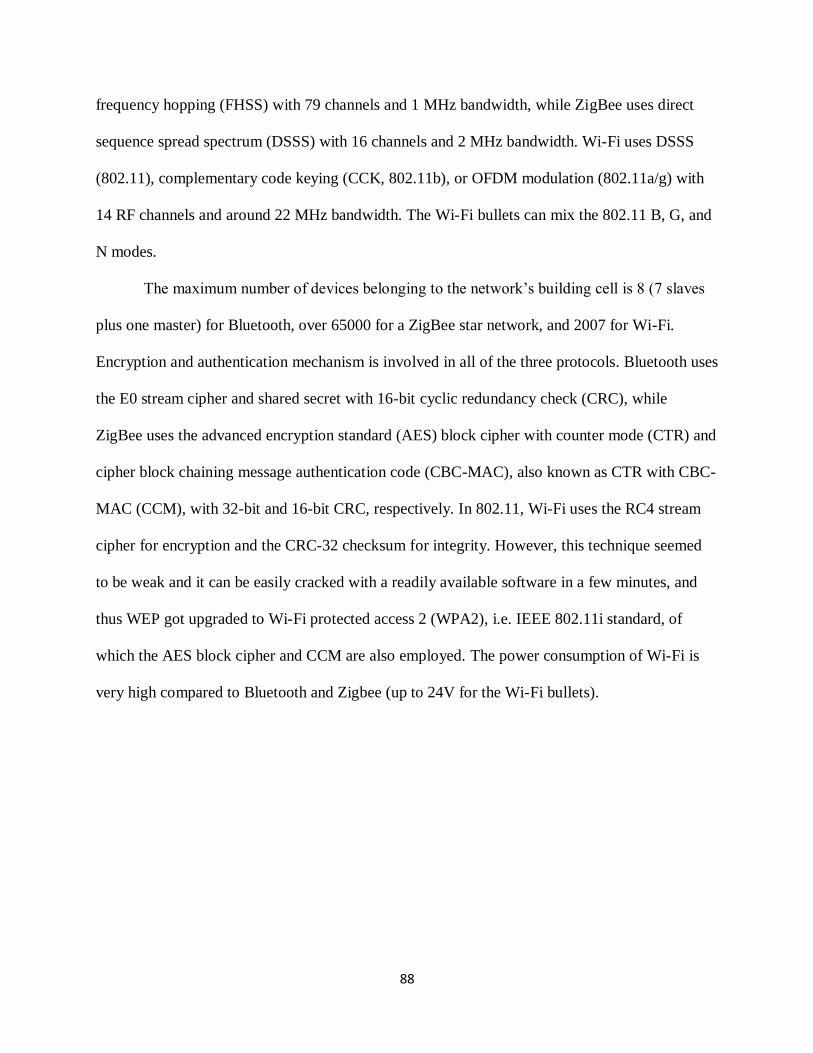
88
frequency hopping (FHSS) with 79 channels and 1 MHz bandwidth, while ZigBee uses direct
sequence spread spectrum (DSSS) with 16 channels and 2 MHz bandwidth. Wi-Fi uses DSSS
(802.11), complementary code keying (CCK, 802.11b), or OFDM modulation (802.11a/g) with
14 RF channels and around 22 MHz bandwidth. The Wi-Fi bullets can mix the 802.11 B, G, and
N modes.
The maximum number of devices belonging to the network’s building cell is 8 (7 slaves
plus one master) for Bluetooth, over 65000 for a ZigBee star network, and 2007 for Wi-Fi.
Encryption and authentication mechanism is involved in all of the three protocols. Bluetooth uses
the E0 stream cipher and shared secret with 16-bit cyclic redundancy check (CRC), while
ZigBee uses the advanced encryption standard (AES) block cipher with counter mode (CTR) and
cipher block chaining message authentication code (CBC-MAC), also known as CTR with CBC-
MAC (CCM), with 32-bit and 16-bit CRC, respectively. In 802.11, Wi-Fi uses the RC4 stream
cipher for encryption and the CRC-32 checksum for integrity. However, this technique seemed
to be weak and it can be easily cracked with a readily available software in a few minutes, and
thus WEP got upgraded to Wi-Fi protected access 2 (WPA2), i.e. IEEE 802.11i standard, of
which the AES block cipher and CCM are also employed. The power consumption of Wi-Fi is
very high compared to Bluetooth and Zigbee (up to 24V for the Wi-Fi bullets).
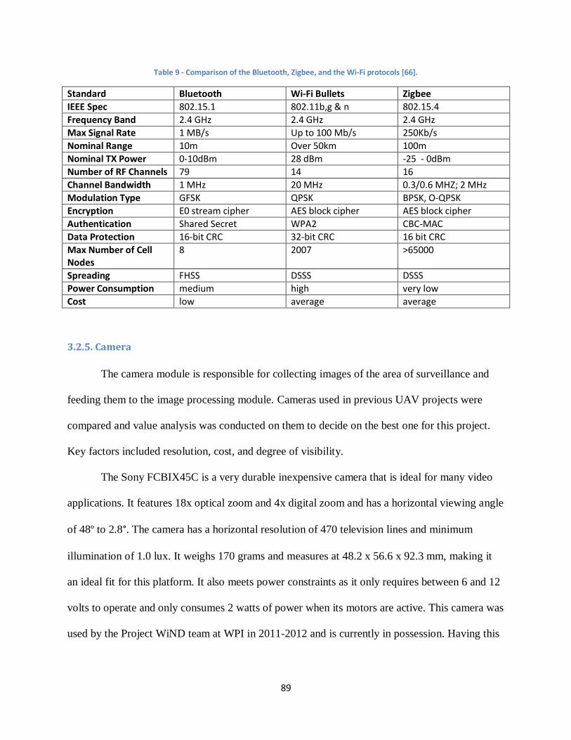
89
Table 9 - Comparison of the Bluetooth, Zigbee, and the Wi-Fi protocols [66].
Standard Bluetooth Wi-Fi Bullets Zigbee
IEEE Spec 802.15.1 802.11b,g & n 802.15.4
Frequency Band 2.4 GHz 2.4 GHz 2.4 GHz
Max Signal Rate 1 MB/s Up to 100 Mb/s 250Kb/s
Nominal Range 10m Over 50km 100m
Nominal TX Power 0-10dBm 28 dBm -25 - 0dBm
Number of RF Channels 79 14 16
Channel Bandwidth 1 MHz 20 MHz 0.3/0.6 MHZ; 2 MHz
Modulation Type GFSK QPSK BPSK, O-QPSK
Encryption E0 stream cipher AES block cipher AES block cipher
Authentication Shared Secret WPA2 CBC-MAC
Data Protection 16-bit CRC 32-bit CRC 16 bit CRC
Max Number of Cell Nodes
8 2007 >65000
Spreading FHSS DSSS DSSS
Power Consumption medium high very low
Cost low average average
3.2.5. Camera
The camera module is responsible for collecting images of the area of surveillance and
feeding them to the image processing module. Cameras used in previous UAV projects were
compared and value analysis was conducted on them to decide on the best one for this project.
Key factors included resolution, cost, and degree of visibility.
The Sony FCBIX45C is a very durable inexpensive camera that is ideal for many video
applications. It features 18x optical zoom and 4x digital zoom and has a horizontal viewing angle
of 48º to 2.8°. The camera has a horizontal resolution of 470 television lines and minimum
illumination of 1.0 lux. It weighs 170 grams and measures at 48.2 x 56.6 x 92.3 mm, making it
an ideal fit for this platform. It also meets power constraints as it only requires between 6 and 12
volts to operate and only consumes 2 watts of power when its motors are active. This camera was
used by the Project WiND team at WPI in 2011-2012 and is currently in possession. Having this
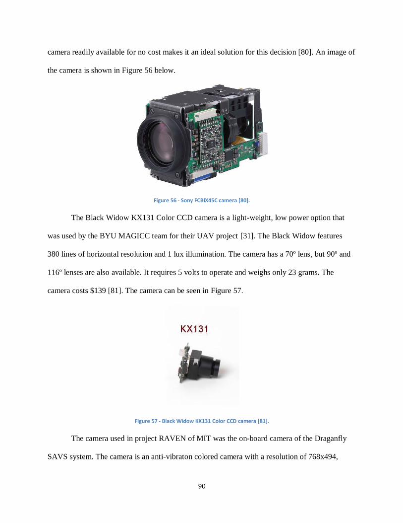
90
camera readily available for no cost makes it an ideal solution for this decision [80]. An image of
the camera is shown in Figure 56 below.
Figure 56 - Sony FCBIX45C camera [80].
The Black Widow KX131 Color CCD camera is a light-weight, low power option that
was used by the BYU MAGICC team for their UAV project [31]. The Black Widow features
380 lines of horizontal resolution and 1 lux illumination. The camera has a 70º lens, but 90º and
116º lenses are also available. It requires 5 volts to operate and weighs only 23 grams. The
camera costs $139 [81]. The camera can be seen in Figure 57.
Figure 57 - Black Widow KX131 Color CCD camera [81].
The camera used in project RAVEN of MIT was the on-board camera of the Draganfly
SAVS system. The camera is an anti-vibraton colored camera with a resolution of 768x494,
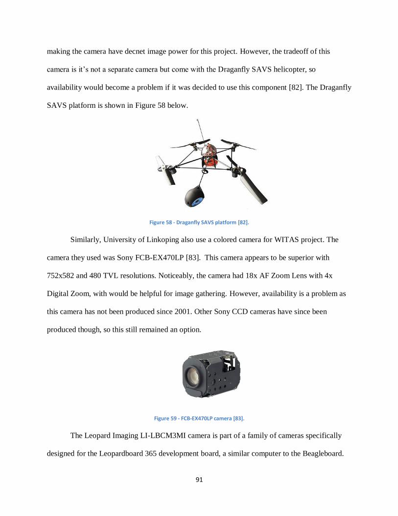
91
making the camera have decnet image power for this project. However, the tradeoff of this
camera is it’s not a separate camera but come with the Draganfly SAVS helicopter, so
availability would become a problem if it was decided to use this component [82]. The Draganfly
SAVS platform is shown in Figure 58 below.
Figure 58 - Draganfly SAVS platform [82].
Similarly, University of Linkoping also use a colored camera for WITAS project. The
camera they used was Sony FCB-EX470LP [83]. This camera appears to be superior with
752x582 and 480 TVL resolutions. Noticeably, the camera had 18x AF Zoom Lens with 4x
Digital Zoom, with would be helpful for image gathering. However, availability is a problem as
this camera has not been produced since 2001. Other Sony CCD cameras have since been
produced though, so this still remained an option.
Figure 59 - FCB-EX470LP camera [83].
The Leopard Imaging LI-LBCM3MI camera is part of a family of cameras specifically
designed for the Leopardboard 365 development board, a similar computer to the Beagleboard.
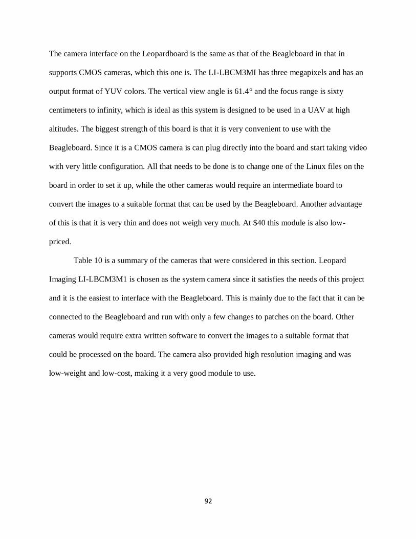
92
The camera interface on the Leopardboard is the same as that of the Beagleboard in that in
supports CMOS cameras, which this one is. The LI-LBCM3MI has three megapixels and has an
output format of YUV colors. The vertical view angle is 61.4° and the focus range is sixty
centimeters to infinity, which is ideal as this system is designed to be used in a UAV at high
altitudes. The biggest strength of this board is that it is very convenient to use with the
Beagleboard. Since it is a CMOS camera is can plug directly into the board and start taking video
with very little configuration. All that needs to be done is to change one of the Linux files on the
board in order to set it up, while the other cameras would require an intermediate board to
convert the images to a suitable format that can be used by the Beagleboard. Another advantage
of this is that it is very thin and does not weigh very much. At $40 this module is also low-
priced.
Table 10 is a summary of the cameras that were considered in this section. Leopard
Imaging LI-LBCM3M1 is chosen as the system camera since it satisfies the needs of this project
and it is the easiest to interface with the Beagleboard. This is mainly due to the fact that it can be
connected to the Beagleboard and run with only a few changes to patches on the board. Other
cameras would require extra written software to convert the images to a suitable format that
could be processed on the board. The camera also provided high resolution imaging and was
low-weight and low-cost, making it a very good module to use.
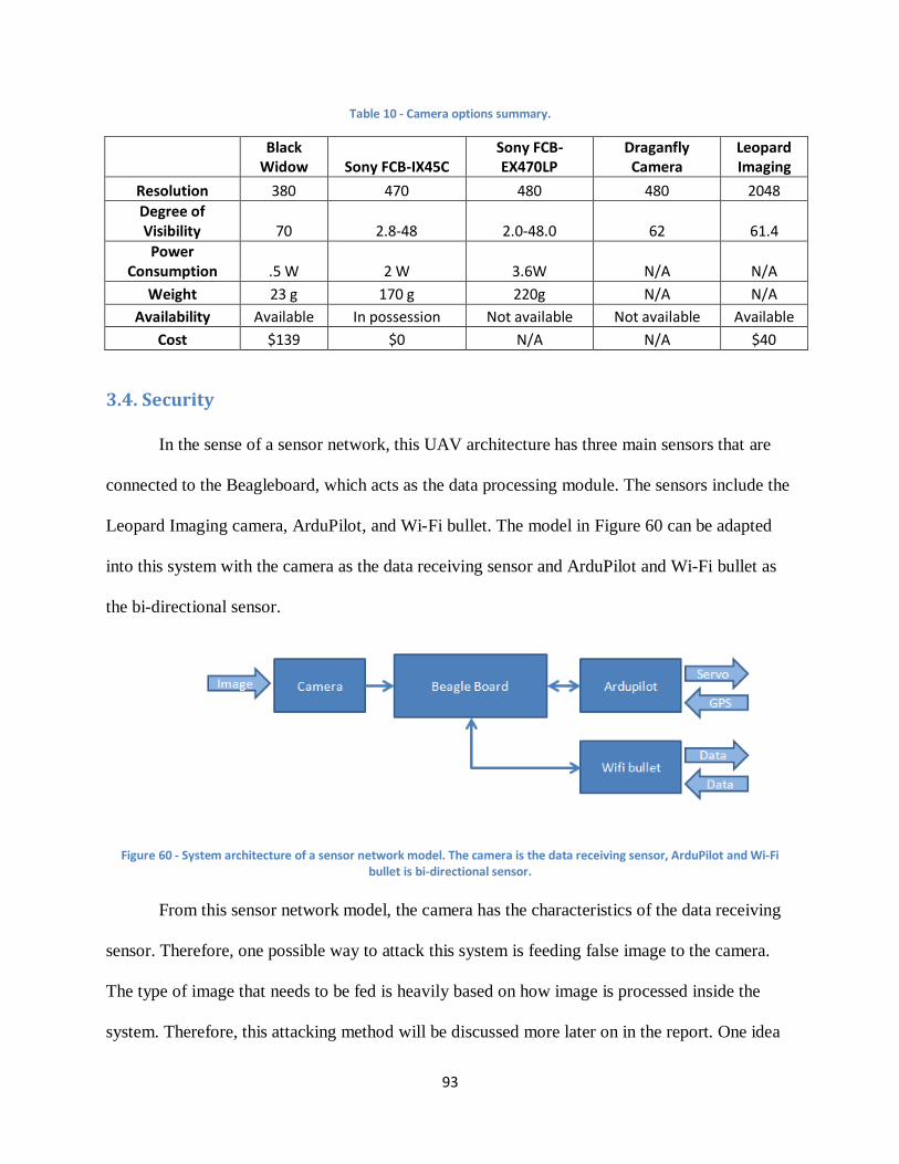
93
Table 10 - Camera options summary.
Black Widow Sony FCB-IX45C
Sony FCB-EX470LP
Draganfly Camera
Leopard Imaging
Resolution 380 470 480 480 2048
Degree of Visibility 70 2.8-48 2.0-48.0 62 61.4
Power Consumption .5 W 2 W 3.6W N/A N/A
Weight 23 g 170 g 220g N/A N/A
Availability Available In possession Not available Not available Available
Cost $139 $0 N/A N/A $40
3.4. Security
In the sense of a sensor network, this UAV architecture has three main sensors that are
connected to the Beagleboard, which acts as the data processing module. The sensors include the
Leopard Imaging camera, ArduPilot, and Wi-Fi bullet. The model in Figure 60 can be adapted
into this system with the camera as the data receiving sensor and ArduPilot and Wi-Fi bullet as
the bi-directional sensor.
Figure 60 - System architecture of a sensor network model. The camera is the data receiving sensor, ArduPilot and Wi-Fi bullet is bi-directional sensor.
From this sensor network model, the camera has the characteristics of the data receiving
sensor. Therefore, one possible way to attack this system is feeding false image to the camera.
The type of image that needs to be fed is heavily based on how image is processed inside the
system. Therefore, this attacking method will be discussed more later on in the report. One idea
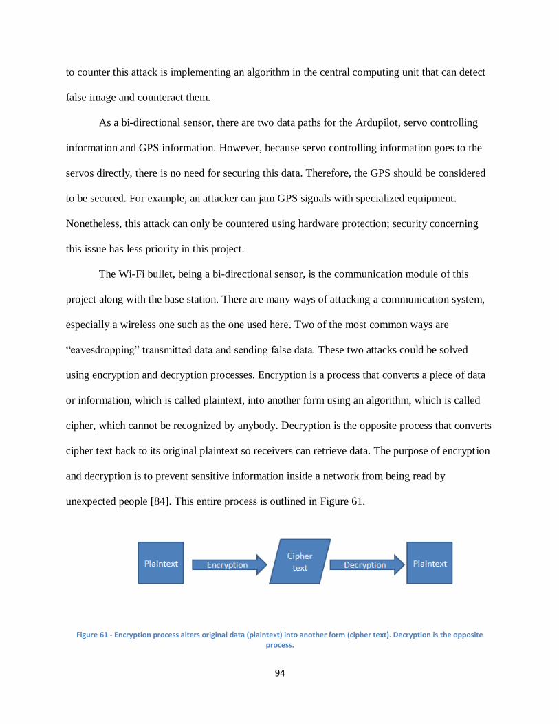
94
to counter this attack is implementing an algorithm in the central computing unit that can detect
false image and counteract them.
As a bi-directional sensor, there are two data paths for the Ardupilot, servo controlling
information and GPS information. However, because servo controlling information goes to the
servos directly, there is no need for securing this data. Therefore, the GPS should be considered
to be secured. For example, an attacker can jam GPS signals with specialized equipment.
Nonetheless, this attack can only be countered using hardware protection; security concerning
this issue has less priority in this project.
The Wi-Fi bullet, being a bi-directional sensor, is the communication module of this
project along with the base station. There are many ways of attacking a communication system,
especially a wireless one such as the one used here. Two of the most common ways are
“eavesdropping” transmitted data and sending false data. These two attacks could be solved
using encryption and decryption processes. Encryption is a process that converts a piece of data
or information, which is called plaintext, into another form using an algorithm, which is called
cipher, which cannot be recognized by anybody. Decryption is the opposite process that converts
cipher text back to its original plaintext so receivers can retrieve data. The purpose of encryption
and decryption is to prevent sensitive information inside a network from being read by
unexpected people [84]. This entire process is outlined in Figure 61.
Figure 61 - Encryption process alters original data (plaintext) into another form (cipher text). Decryption is the opposite process.
95
3.5. Tasks Division
The goal of this project is to deliver a fully functional platform on time and within
budget. Planning, organizing, securing, managing, leading, and controlling are significant for the
ultimate success of this project.
This project was split up evenly between the three people in the group. All of the
modules of the platform architecture were assigned to one person each to design and implement
them. The camera, autopilot, central control unit, and image processing, encryption, and
communications modules will be assigned to one person. While everyone got to work on these
parts of the project completed, one person was ultimately responsible for their success.
One person was responsible for the image processing and central computing modules.
Since the algorithm was implemented in software, a CPU was used to complete the task. This
was programmed in C++. This task requires experience with these devices by completing
relevant course work and projects. Another person was responsible for the communication
module of the platform. This required courses to have been completed related to communication
and a solid understanding of its different methods. The final task included the responsibility of
the autopilot and camera modules. This required relevant coursework in controls engineering a
solid understanding of how the sensors on the autopilot work. All tasks were divided evenly and
all members contributed equally to the success of the project.
3.4. Chapter Summary
This chapter contains the proposed approach of designing a UAV platform framework
architecture that can be used for blob detection and security testing. The platform consists of
generic basic components of a UAV: an autopilot module, an image processing module, a central
96
computing unit, and an encryption module. The modules are chosen from several candidates with
a value analysis processes using typical UAV constraints like size, weight, power, price, speed
and availability. With research done on many types of computing choices, conducted along with
cautious a selection process, more knowledge was gained about UAV systems and architectures.

97
4. Design Methodology and Implementation
Although the main focus of this project is building a UAV platform that can serve as a
test bed for enhancing securing, the platform should be able to have general features of an actual
UAV system. All modules of the system must be able to process and communicate data with
each other. Since the concerns of this project are more focused on the hardware side, software
implementation that is not security related could be really simple and off-the-shelf algorithms
obtained from the Internet. For example, the image processing module can use the image
processing code from an algorithm that simply outputs a certain value based on colors contained
in an image. The autopilot module is an independent board and did not require much custom
configuration. The central computing unit should be able to receive data from the image
processing and autopilot modules and process and transfer the data to the Wi-Fi bullet. To check
if the modules function correctly, they needed to be tested at first individually and then as a
complete system. Also, the image processing module needed to be tested by using both fixed and
motioned pictures. Not much needed to be tested the on autopilot module besides ensuring that
the module worked correctly. For the central computing unit, it needs to be made sure the the
module logic as well as the data line work fine.
For security concerns, several testing procedures needed to be developed to ensure data
inside the system was secured. Most of the tests were in forms of attacks toward the system.
Attacks against the image processing module were done by using light to generate false images
that were detected by the camera and countermeasures were developed against these attacks.
Also wireless attacks were used that made it possible to intercept packets being sent between the
Beagleboard and ground station and were able to alter the configuration of the Wi-Fi bullets.
98
4.1. Autopilot
The ArduPilot autopilot module was used to determine the coordinates and altitude of the
plane when a positive hit was detected. This component was essential to the project as it would
output the longitude, latitude, and altitude of the plane on a detected hit. The progression of
integrating this component went from reading the output via software on a laptop to isolate only
certain relevant parameters.
The autopilot was first connected to a laptop running Windows 7 via USB to test its
functionality [85]. The program ArduPilot Mega Planner was initially used to read the
information from the serial port. This software allowed made it possible to download the correct
firmware for this module and to track the progress of the module by outputting information such
as altitude, latitude, longitude, roll, pitch, and yaw in a GUI. The GUI also contained a window
that provided a virtualization of the flight and when the GPS was plugged in a real-time map of
where the autopilot was could be seen.
After the correct firmware was downloaded and it was verified that the autopilot board
was working properly, steps were taken towards interfacing it with the Beagleboard. Initial
attempts included trying to send commands between the two boards to activate certain LED
lights on the autopilot. However, it was then realized that sending commands would not be
necessary information just needed to be read from the board, it did not need to perform any other
actions. The objective then became to be able to view the raw data from the board.
Since a USB was being used to connect the two boards a common Linux application,
Minicom, was used to read the Beagleboard’s serial port [86]. Using Minicom made it possible
to read the board right from the Linux terminal on the Beagleboard. After configuring the
program to run using the correct settings the output was able to be read from the ArduPilot. This
99
output was mostly composed of machine code called Mavlink that is specific for remotely
controlled vehicles. By itself this information was mostly useless as it could not be read.
However it was possible to use the Mission Planner software to be to read a Mavlog file and
recreate the simulation of the flight. This allowed all of the relevant parameters to be read on the
software. After this was figured out, a method was found to output information from the Linux
terminal into a text file. This file was saved as a Mavlog format and it was able to be transferred
from the Beagleboard to a laptop running the ArduPilot software to recreate the “flight” and get
the relevant data.
Once the raw data was able to be read from the serial port the next step was integrating
the code with the blob detection algorithm. To do this a separate C program was found that could
be used to read the serial port of a Linux machine. This code set the input and output baud rates
for the serial ports as well as specified what directory needed to be read for the serial port. This
code was able to be used to read from the serial port 10000 times to create a Mavlog file that
could be read by the GUI. It was tested by itself and then modified to save all of the results in a
separate text file. Once it was verified that this was working this code was inserted into the blob
detection algorithm to run whenever an object was detected. This would save the Mavlog file
into the directory the Beagleboard was currently in. The Mavlog file was able to be accessed
from the Windows laptop and run on the autopilot software to find the specific parameters that
were being looked for.
While this method worked it was inefficient. Having to monitor the current directory for
a new file and running it in the software took too long and gave too much information for what
was desired. To remedy the situation, ways were searched for in which certain variables could be
isolated and then outputted directly into the terminal. This was accomplished by further studying
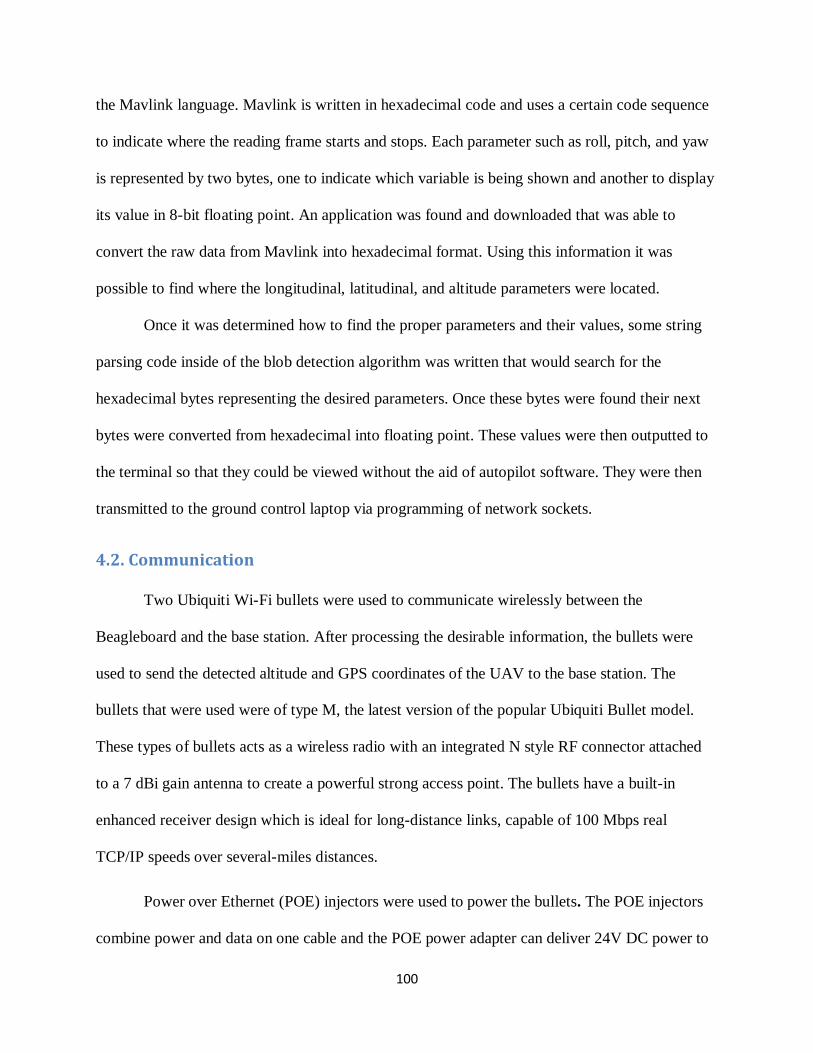
100
the Mavlink language. Mavlink is written in hexadecimal code and uses a certain code sequence
to indicate where the reading frame starts and stops. Each parameter such as roll, pitch, and yaw
is represented by two bytes, one to indicate which variable is being shown and another to display
its value in 8-bit floating point. An application was found and downloaded that was able to
convert the raw data from Mavlink into hexadecimal format. Using this information it was
possible to find where the longitudinal, latitudinal, and altitude parameters were located.
Once it was determined how to find the proper parameters and their values, some string
parsing code inside of the blob detection algorithm was written that would search for the
hexadecimal bytes representing the desired parameters. Once these bytes were found their next
bytes were converted from hexadecimal into floating point. These values were then outputted to
the terminal so that they could be viewed without the aid of autopilot software. They were then
transmitted to the ground control laptop via programming of network sockets.
4.2. Communication
Two Ubiquiti Wi-Fi bullets were used to communicate wirelessly between the
Beagleboard and the base station. After processing the desirable information, the bullets were
used to send the detected altitude and GPS coordinates of the UAV to the base station. The
bullets that were used were of type M, the latest version of the popular Ubiquiti Bullet model.
These types of bullets acts as a wireless radio with an integrated N style RF connector attached
to a 7 dBi gain antenna to create a powerful strong access point. The bullets have a built-in
enhanced receiver design which is ideal for long-distance links, capable of 100 Mbps real
TCP/IP speeds over several-miles distances.
Power over Ethernet (POE) injectors were used to power the bullets. The POE injectors
combine power and data on one cable and the POE power adapter can deliver 24V DC power to
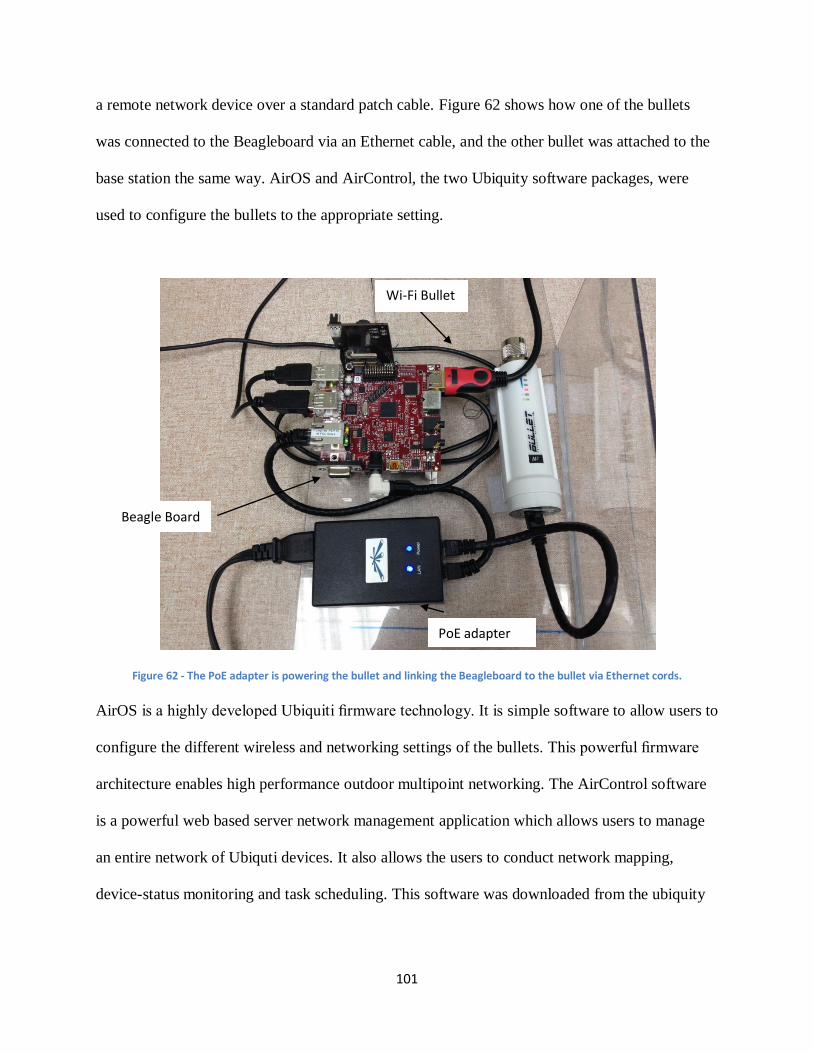
101
a remote network device over a standard patch cable. Figure 62 shows how one of the bullets
was connected to the Beagleboard via an Ethernet cable, and the other bullet was attached to the
base station the same way. AirOS and AirControl, the two Ubiquity software packages, were
used to configure the bullets to the appropriate setting.
Figure 62 - The PoE adapter is powering the bullet and linking the Beagleboard to the bullet via Ethernet cords.
AirOS is a highly developed Ubiquiti firmware technology. It is simple software to allow users to
configure the different wireless and networking settings of the bullets. This powerful firmware
architecture enables high performance outdoor multipoint networking. The AirControl software
is a powerful web based server network management application which allows users to manage
an entire network of Ubiquti devices. It also allows the users to conduct network mapping,
device-status monitoring and task scheduling. This software was downloaded from the ubiquity
PoE adapter
Wi-Fi Bullet
Beagle Board
102
main website, and it was possible to login into the configuration page using the Ubiquity
username and password provided.
Configuring the bullets with the correct settings involved three major steps that included
connecting the hardware, setting the ground station and Beagleboard to the correct IP addresses,
and setting the bullets to the right settings to be able to communicate with one another. As
mentioned earlier, the POE injector had two Ethernet ports. One of the ports was connected to
the bullet via an Ethernet cable to power the bullet, and the second port was for the local area
network. This port was connected to the Beagleboard via Ethernet cable to transfer data to the
bullet. The same configurations were used at the base station end. The second POE injector was
used to power the second bullet, and to link the base station to the LAN line.
The Wi-Fi bullets can be used for different applications such as a simple access point,
wireless repeater, or a bridge. At first, the two Wi-Fi bullets were connected to two separate
computers to configure the computer to be able to setup the devices. The IP address and the
subnet mask of one of the computers were set as 192.168.1.21 and 255.255.255.0 respectively.
The second computer’s IP address and subnet mask were set as 192.168.1.20 and 255.255.255.0
respectively. 192.168.1.20 and 192.168.1.21 are the IP addresses of the bullets. By adjusting the
computers IP addresses, it was possible to log in into the ubnt server by typing either
http://192.169.1.20 or http://192.169.1.21 in the browser and adjusting the networking and
wireless settings according to the needs of this project.
One of the bullets needed to be setup to act as an access point. For this purpose, the
Wireless Mode was chosen as: Access Point WDS with the MAC address of the second bullet
entered in the WDS section as seen in Figure 63. SSID: UBNT, Channel Spectrum Width: 20
MHz, Channel: 1-2412 MHz range, 10 dBm output power, and WPA wireless security. Figure 64
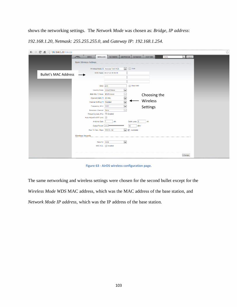
103
shows the networking settings. The Network Mode was chosen as: Bridge, IP address:
192.168.1.20, Netmask: 255.255.255.0, and Gateway IP: 192.168.1.254.
Figure 63 - AirOS wireless configuration page.
The same networking and wireless settings were chosen for the second bullet except for the
Wireless Mode WDS MAC address, which was the MAC address of the base station, and
Network Mode IP address, which was the IP address of the base station.
Bullet’s MAC Address
AddeAddress
Choosing the
Wireless
Settings
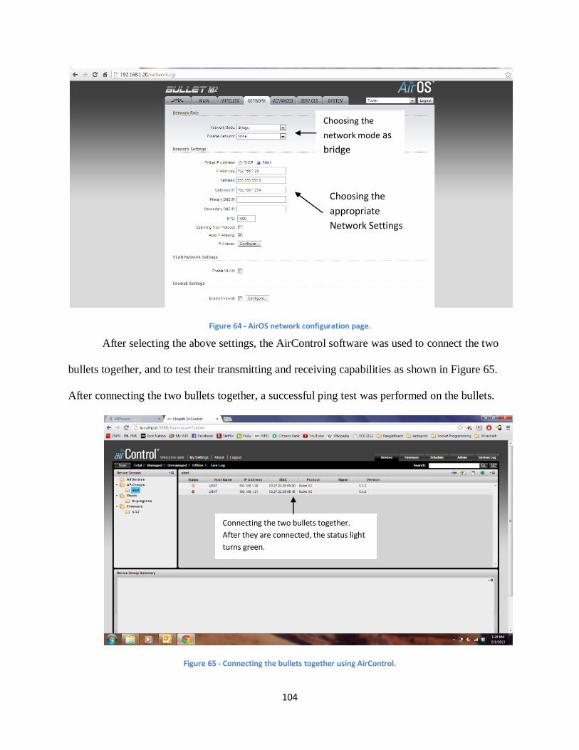
104
Figure 64 - AirOS network configuration page.
After selecting the above settings, the AirControl software was used to connect the two
bullets together, and to test their transmitting and receiving capabilities as shown in Figure 65.
After connecting the two bullets together, a successful ping test was performed on the bullets.
Figure 65 - Connecting the bullets together using AirControl.
Choosing the
network mode as
bridge
Choosing the
appropriate
Network Settings
Connecting the two bullets together.
After they are connected, the status light
turns green.
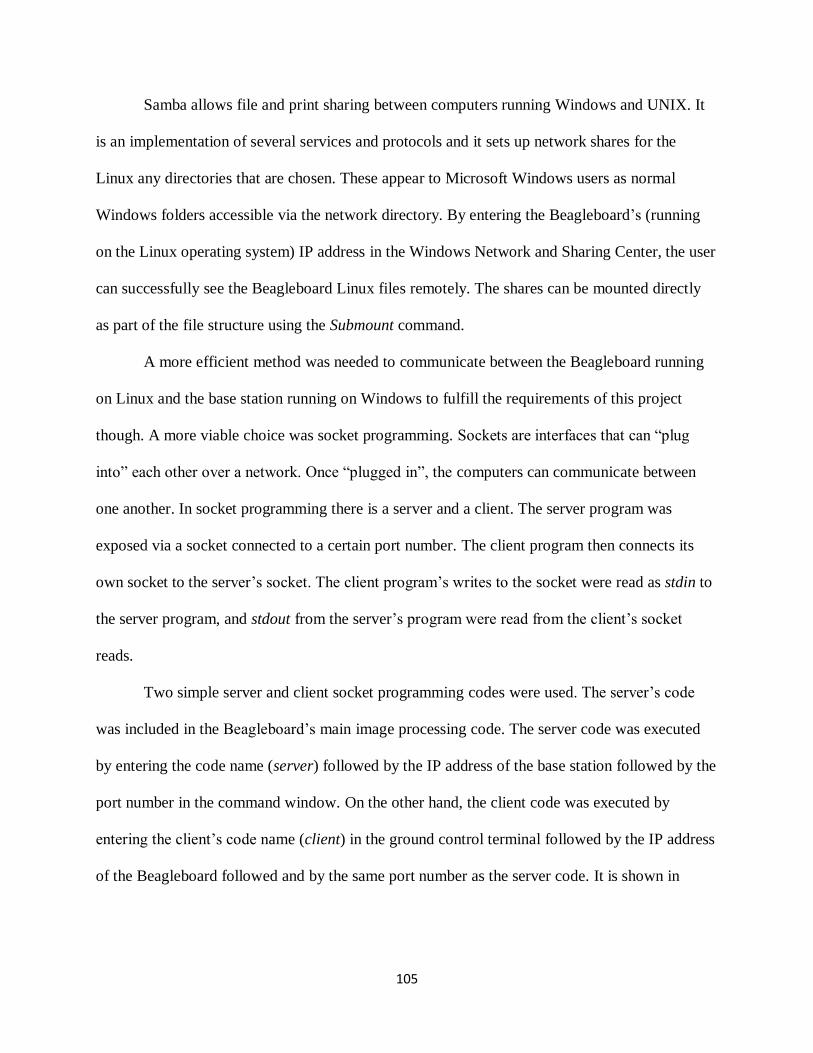
105
Samba allows file and print sharing between computers running Windows and UNIX. It
is an implementation of several services and protocols and it sets up network shares for the
Linux any directories that are chosen. These appear to Microsoft Windows users as normal
Windows folders accessible via the network directory. By entering the Beagleboard’s (running
on the Linux operating system) IP address in the Windows Network and Sharing Center, the user
can successfully see the Beagleboard Linux files remotely. The shares can be mounted directly
as part of the file structure using the Submount command.
A more efficient method was needed to communicate between the Beagleboard running
on Linux and the base station running on Windows to fulfill the requirements of this project
though. A more viable choice was socket programming. Sockets are interfaces that can “plug
into” each other over a network. Once “plugged in”, the computers can communicate between
one another. In socket programming there is a server and a client. The server program was
exposed via a socket connected to a certain port number. The client program then connects its
own socket to the server’s socket. The client program’s writes to the socket were read as stdin to
the server program, and stdout from the server’s program were read from the client’s socket
reads.
Two simple server and client socket programming codes were used. The server’s code
was included in the Beagleboard’s main image processing code. The server code was executed
by entering the code name (server) followed by the IP address of the base station followed by the
port number in the command window. On the other hand, the client code was executed by
entering the client’s code name (client) in the ground control terminal followed by the IP address
of the Beagleboard followed and by the same port number as the server code. It is shown in
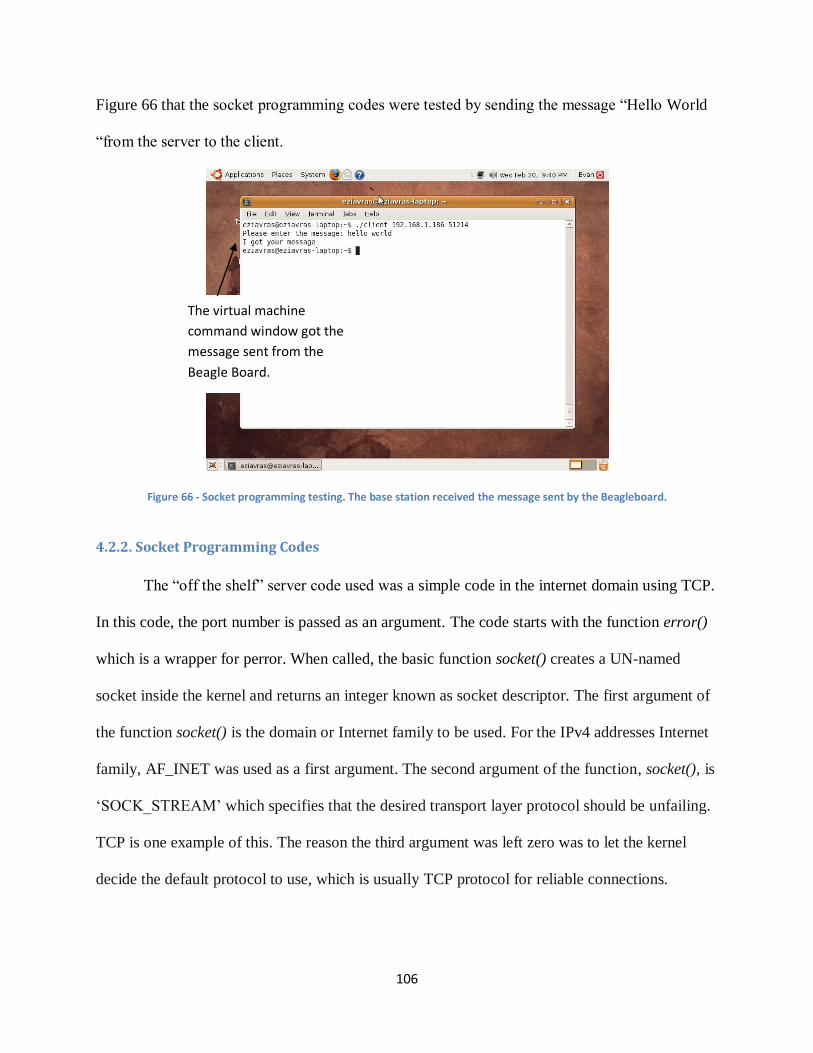
106
Figure 66 that the socket programming codes were tested by sending the message “Hello World
“from the server to the client.
Figure 66 - Socket programming testing. The base station received the message sent by the Beagleboard.
4.2.2. Socket Programming Codes
The “off the shelf” server code used was a simple code in the internet domain using TCP.
In this code, the port number is passed as an argument. The code starts with the function error()
which is a wrapper for perror. When called, the basic function socket() creates a UN-named
socket inside the kernel and returns an integer known as socket descriptor. The first argument of
the function socket() is the domain or Internet family to be used. For the IPv4 addresses Internet
family, AF_INET was used as a first argument. The second argument of the function, socket(), is
‘SOCK_STREAM’ which specifies that the desired transport layer protocol should be unfailing.
TCP is one example of this. The reason the third argument was left zero was to let the kernel
decide the default protocol to use, which is usually TCP protocol for reliable connections.
The virtual machine
command window got the
message sent from the
Beagle Board.
107
When the function bind() was called, it assigned the details specified in the structure
‘serv_addr’ to the socket created in the step above. The details include the family/domain, the
interface to listen on (in case the system has multiple interfaces to network) and the port on
which the server will wait for the client requests to come.
The second argument of the function, listen() (5), specified the maximum number of
client connections that the server will queue for this listening socket, which became a fully
functional listening socket after the call to the function listen. As soon as the server gets a request
from the client, it prepares the date and time and writes on the client socket through the
descriptor returned by accept().
The same thing was done as in the server code. A socket was created by calling the
socket() function. A struct including information about the IP address of the remote host and its
port was defined. The function connect () tried to connect this socket with the remote socket (IP
address and port of the remote host) after the function connect() was called. The client usually
can have its socket lined with any port unlike the server, which needs a well-known socket. This
means that binding the client socket on a particular port is not needed here [87].
Once the sockets were connected, the server sends the data and time information on
clients socket through clients socket descriptor and client was able to read it through normal
read call on the its socket descriptor.
4.2.3. Use of Virtual Machine
The sample socket programs that were found online were confirmed to work on the
Beagleboard itself. Messages could be sent between two terminal windows using the loopback
address to specify where the send the message. However more work had to be done before
getting them to work over a different computer.
108
The objective was to use the Beagleboard to send messages back and forth between it and
the ground control laptop. It was planned to do this by connecting a laptop running Linux
Ubuntu 12.04 to the Beagleboard with an Ethernet cable and compiling both the server and client
programs on it. First, it was verified that the programs worked the laptop by sending messages
from one terminal window to another within it using the loopback address like had been done on
the Beagleboard. This worked with no difficulty. However, problems were encountered when it
was attempted to send messages between the laptop and board. The Beagleboard was not able to
read the connection to the laptop and it was not possible to communicate with it.
After uncovering this problem, sending messages between the two machines was
attempted by running Windows 7 on the laptop rather than Linux. The board and laptop were
connected via Ethernet and this configuration allowed for successful pinging of the board from
the laptop and vice versa. MinGW was then downloaded to the laptop to compile the socket
programming code. MinGW provided an interface that was similar to the Linux shell that was
more convenient to work with because of familiarity. A simple “Hello World” program was
compiled and run using the gcc compiler on MinGW to verify that it worked as intended. The
socket programs proved to be more complicated to compile however. Multiple headers that were
included in the codes were specifically for Linux and would not compile in Windows. A way
was found to be able to find a way to circumvent this problem for one of the headers but could
not for the other ones.
The next attempted solution was to look for a way to program the sockets in Windows.
Some simple server and client codes were found online but difficulty was experienced in
compiling them as they returned errors which were difficult to understand. Since nobody in the
109
group had any experience in programming sockets, alternate solutions were looked for instead of
trying to modify the original code.
Problems were experienced when using just one operating system on the ground control
laptop. The computer and the board could be connected successfully when running Windows 7
but it was difficult to compile any socket programs on the laptop. When running Ubuntu on the
laptop, it was possible to compile the programs but not to establish a connection between the
Beagleboard and laptop. To solve this problem a virtual machine (VM) was installed on the
laptop running Windows that would run Linux Ubuntu 8.04. This solution made is possible to
connect the board to the computer successfully in Windows while running the socket software in
Linux like it was written for. The virtual machine software used was Oracle VM VirtualBox. The
Ubuntu image was downloaded online set up on VirtualBox. Once the system was installed the
server and client codes were compiled and run to send messages from one terminal to another on
the virtual machine as had been done before in Linux.
Once this was done, difficulty was had in figuring out the right configuration method to
get the board communicating with the virtual machine. The default network setting on the VM
was a NAT configuration, but it was not possible to ping the board using this method. It was then
attempted to bridge the Wi-Fi connection from the laptop, the VM, and the Beagleboard and
changing the network setting to bridged. While this worked successfully once, it did not work the
next time the board was connected to the laptop. It was still possible to ping the board from
Windows but not from the VM however.
To remedy this, a static IP address was assigned to the Beagleboard. The Beagleboard has
a default dynamic IP address by default and that causes it to assign itself a new one on each boot-
up. It was decided to make this address static so that the same address would be assigned each
110
time. This was done so that the laptop would be able to connect to the board without having to
look up the address on the monitor. This was able to be done by modifying one of the scripts on
the Beagleboard that configured all of the interfaces on it. Doing this fixed the problem and
made it so that communication between the board and laptop was possible through the VM. First
the board was pinged through the Ubuntu terminal and then the socket networks were
configured. One issue that remained unsolved was that communication was only possible
between both systems if the client was running on the laptop and the server was running on the
Beagleboard. Communication was not possible if it was set up the opposite way. It was
suspected that this was due to the Beagleboard trying to connect to the Windows operating
system if the client was run in it and not the VM. This would not prove to be a major issue
however as communication was still possible as long as the server program was running on one
machine and the client on the other.
4.3. Image Processing
The image processing module was a very important part of this architecture as it was the
main data processing sensor. Parts of this module included connecting the camera, downloading
OpenCV, and finding a suitable blob detection algorithm that can be used to for this project.
The camera was one of the first components that were integrated with the Beagleboard
[88]. It was made by Leopard Imaging and was the LI-LBCM3M1 model. This was a CMOS
transistor camera composed of three megapixels, giving good quality of output video of YUV
format. This camera was specially created for the Leopard Board, which has the same camera
interface as the Beagleboard. The ability to plug the camera straight into the board eliminated the
need for any sort of intermediate components such as a decoder to interface the camera with the
board.
111
Another advantage of using this camera was it being supported by the version of Linux
Angstrom that was used on the board. To enable it, some U-Boot files were modified by simply
adding several command lines so that the camera could be recognized by the Beagleboard. Once
these lines were added into the U-Boots file, the system was able to take pictures from the
camera and view the video output on the monitor screen using the program Mplayer. It was also
possible to record videos by using the application Mencoder.
The role of the image processing module is to process data that comes from camera. To
do that, there was a need to use many tools for the sole purpose of image processing. Instead of
developing an image processing module from scratch, which is impractical for both time and
resources for this project, a library package called Open Source Computer Vision Library
(OpenCV) was utilized. OpenCV is a free image processing library that contains many helpful
and powerful image processing functions and algorithms. Furthermore, the library is developed
and utilized by a big open source community that conducts many projects with an image
processing purpose. The projects range from simple color changing programs to more
sophisticated ones like face recognition. Being both free and widely used, OpenCV fit into this
project both financially and conveniently.
OpenCV could be easily downloaded from its official site. The library supports almost all
mainstream operating system like Windows, Mac, and UNIX based operating systems. The
downloading and installation process was fairly simple with instruction from the library’s
documentation site. Upon downloading and building the Linux version package of OpenCV, this
library was ready to be used in the program.
The first version image processing algorithm that was used was based on a simple
function that turns a colored picture into grayscale picture. Although converting the image into
112
grayscale was not the goal of this project and, in fact, this function was not even used in the final
design, this function was used at first for two main reasons: to be able to know that OpenCV had
been installed correctly and to have first-hand experience with image processing. This program
first loaded an image from a picture file and stored it in program memory with a pointer of
OpenCV’s image type called IplImage. The process was done using the cvLoadImage function of
OpenCV. Next, the colored image is converted into grayscale image using a function called
cvColor with the special parameter, CV_RGB2GRAY. After that, the image was successfully
converted into grayscale.
Since converting image to grayscale was a very simple process and it did not have any
real use as image processing algorithm for this project, a more sophisticated function was
developed based on this version. The second version of the image processing module has two
new features: being able to load live images from the camera instead of a file and filtering out a
part of picture based on its color. For interacting with the camera, another type of data was
introduced into the program as IplImage which can only be used for the image. In order to be
able to store a video, which is basically a series of many images, a data type called CvCapture
was used. Furthermore, with an OpenCV function called cvCaptureFromCAM, live images that
came were able to be captured from the camera and stored in memory. With this, frames, or
images, of the video were extracted using the cvQueryframe function and stored as an IplImage
format. Each frame that had been extracted then went through the color-to-grayscale process that
had been implemented. However, instead of stopping at this point, another layer of image
processing was applied. This idea for this layer was to separate the part of the image that had
color level (or in this case gray level) less than a threshold level and the one that is bigger. Using
the cvThreshold function and the THRESH_BINARY option given to this function, the grayscale
113
image could be turned into a black and white image where the black area was the area with gray
level less than the threshold value and white otherwise.
As OpenCV’s functionality was able to be confirmed by simple image processing
programs that worked with live images from the camera, the image processing module was
decided to be upgraded to another algorithm that was more complex and more suitable for the
goal of this project. Therefore, a third version of the image processing module was designed and
implemented.
In order to figure out which algorithm should be use from this module, the design goal
for this project was considered. First and foremost, although UAV technology is applied with
various purposes in both military and civilian field, most of the time UAVs’ cameras are used for
detecting abnormalities in the area being watched (people, animals, wildfire, etc.). Secondly,
since the ultimate goal was not developing an image processing algorithm but detecting
exploitable flaws in UAV systems, the image processing module should only take up a fair
amount of the time budget. Lastly, as the UAV being built was supposed to fit a standard UAV
architecture, its functionality should also be common, rather than focusing on a specific
direction. Therefore, the image processing algorithm was decided to be a red color detection
program. The reason for choosing this algorithm was color detection was a very widely used
image processing technique and it did not require too much time and knowledge to be able to
implement. Also, red was a less frequent color that can be found in nature, making it a color that
would probably indicate an abnormality. Thus, the red color detection algorithm fit into the
project scale and purpose.
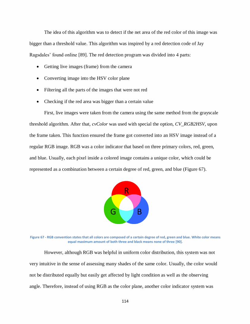
114
The idea of this algorithm was to detect if the net area of the red color of this image was
bigger than a threshold value. This algorithm was inspired by a red detection code of Jay
Ragsdales’ found online [89]. The red detection program was divided into 4 parts:
Getting live images (frame) from the camera
Converting image into the HSV color plane
Filtering all the parts of the images that were not red
Checking if the red area was bigger than a certain value
First, live images were taken from the camera using the same method from the grayscale
threshold algorithm. After that, cvColor was used with special the option, CV_RGB2HSV, upon
the frame taken. This function ensured the frame got converted into an HSV image instead of a
regular RGB image. RGB was a color indicator that based on three primary colors, red, green,
and blue. Usually, each pixel inside a colored image contains a unique color, which could be
represented as a combination between a certain degree of red, green, and blue (Figure 67).
Figure 67 - RGB convention states that all colors are composed of a certain degree of red, green and blue. White color means equal maximum amount of both three and black means none of three [90].
However, although RGB was helpful in uniform color distribution, this system was not
very intuitive in the sense of assessing many shades of the same color. Usually, the color would
not be distributed equally but easily get affected by light condition as well as the observing
angle. Therefore, instead of using RGB as the color plane, another color indicator system was
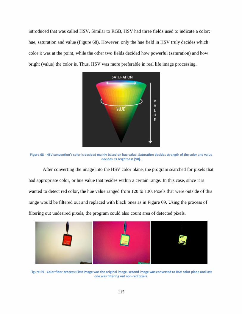
115
introduced that was called HSV. Similar to RGB, HSV had three fields used to indicate a color:
hue, saturation and value (Figure 68). However, only the hue field in HSV truly decides which
color it was at the point, while the other two fields decided how powerful (saturation) and how
bright (value) the color is. Thus, HSV was more preferable in real life image processing.
Figure 68 - HSV convention’s color is decided mainly based on hue value. Saturation decides strength of the color and value decides its brightness [90].
After converting the image into the HSV color plane, the program searched for pixels that
had appropriate color, or hue value that resides within a certain range. In this case, since it is
wanted to detect red color, the hue value ranged from 120 to 130. Pixels that were outside of this
range would be filtered out and replaced with black ones as in Figure 69. Using the process of
filtering out undesired pixels, the program could also count area of detected pixels.
Figure 69 - Color filter process: First image was the original image, second image was converted to HSV color plane and last one was filtering out non-red pixels.
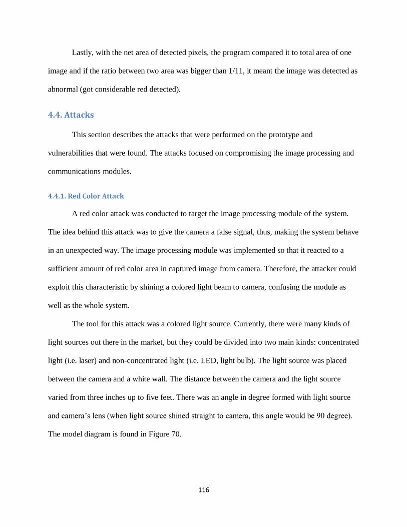
116
Lastly, with the net area of detected pixels, the program compared it to total area of one
image and if the ratio between two area was bigger than 1/11, it meant the image was detected as
abnormal (got considerable red detected).
4.4. Attacks
This section describes the attacks that were performed on the prototype and
vulnerabilities that were found. The attacks focused on compromising the image processing and
communications modules.
4.4.1. Red Color Attack
A red color attack was conducted to target the image processing module of the system.
The idea behind this attack was to give the camera a false signal, thus, making the system behave
in an unexpected way. The image processing module was implemented so that it reacted to a
sufficient amount of red color area in captured image from camera. Therefore, the attacker could
exploit this characteristic by shining a colored light beam to camera, confusing the module as
well as the whole system.
The tool for this attack was a colored light source. Currently, there were many kinds of
light sources out there in the market, but they could be divided into two main kinds: concentrated
light (i.e. laser) and non-concentrated light (i.e. LED, light bulb). The light source was placed
between the camera and a white wall. The distance between the camera and the light source
varied from three inches up to five feet. There was an angle in degree formed with light source
and camera’s lens (when light source shined straight to camera, this angle would be 90 degree).
The model diagram is found in Figure 70.
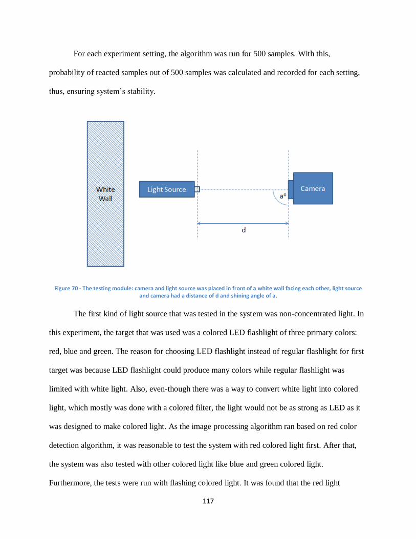
117
For each experiment setting, the algorithm was run for 500 samples. With this,
probability of reacted samples out of 500 samples was calculated and recorded for each setting,
thus, ensuring system’s stability.
Figure 70 - The testing module: camera and light source was placed in front of a white wall facing each other, light source and camera had a distance of d and shining angle of a.
The first kind of light source that was tested in the system was non-concentrated light. In
this experiment, the target that was used was a colored LED flashlight of three primary colors:
red, blue and green. The reason for choosing LED flashlight instead of regular flashlight for first
target was because LED flashlight could produce many colors while regular flashlight was
limited with white light. Also, even-though there was a way to convert white light into colored
light, which mostly was done with a colored filter, the light would not be as strong as LED as it
was designed to make colored light. As the image processing algorithm ran based on red color
detection algorithm, it was reasonable to test the system with red colored light first. After that,
the system was also tested with other colored light like blue and green colored light.
Furthermore, the tests were run with flashing colored light. It was found that the red light
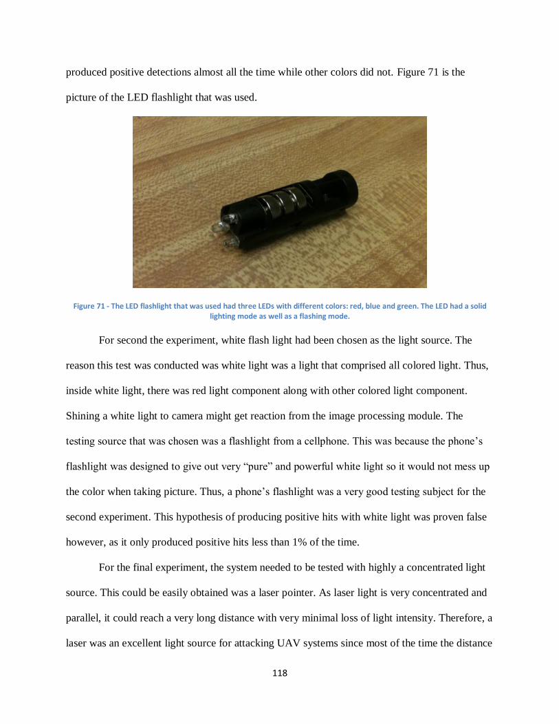
118
produced positive detections almost all the time while other colors did not. Figure 71 is the
picture of the LED flashlight that was used.
Figure 71 - The LED flashlight that was used had three LEDs with different colors: red, blue and green. The LED had a solid lighting mode as well as a flashing mode.
For second the experiment, white flash light had been chosen as the light source. The
reason this test was conducted was white light was a light that comprised all colored light. Thus,
inside white light, there was red light component along with other colored light component.
Shining a white light to camera might get reaction from the image processing module. The
testing source that was chosen was a flashlight from a cellphone. This was because the phone’s
flashlight was designed to give out very “pure” and powerful white light so it would not mess up
the color when taking picture. Thus, a phone’s flashlight was a very good testing subject for the
second experiment. This hypothesis of producing positive hits with white light was proven false
however, as it only produced positive hits less than 1% of the time.
For the final experiment, the system needed to be tested with highly a concentrated light
source. This could be easily obtained was a laser pointer. As laser light is very concentrated and
parallel, it could reach a very long distance with very minimal loss of light intensity. Therefore, a
laser was an excellent light source for attacking UAV systems since most of the time the distance
119
from the attacker (usually at ground level) to the UAV’s camera would be very big. With a laser
pointer, the attacker’s false colored light signal could easily reach the camera and mess up image
processing module. The laser pointer was found to be able to affect the processing module at
greater distances and angles than the LED flashlight. Figure 72 is a picture of an example of a
laser pointer.
Figure 72 - The laser light that was used was a level measurement laser. Its light could reach more than 5 feet distance [91].
4.4.2. Wireless Attacks
The second main attack focused on compromising the wireless communication module of
the UAV prototype. The first method used for this was by using the software, Wireshark, to try
and intercept data sent from one bullet to another. This would allow an authorized user to see the
location of the detected objects. The second method used was using a number of Linux scripts
under the suite of Aircrack-ng to attempt to jam the bullet’s Wi-Fi network and crack its WEP
code.
120
4.4.2.1. Wireshark
Wireshark is a powerful tool to analyze networks with a graphical interface. This can be
done by choosing the interfaces to be monitored. Wireshark usually captures network adapters,
and detects all activities on the adapters including TCP, UDP, and HTTP. Wireshark shows the
source and destination of the packs being transmitted using certain networks, it also shows the
protocol under which the packets are being transmitted and gives lot of information about the
data inside the packets. TCP streams can be followed using Wireshark by selecting the TCP
packet in the packet listing of connections, and choosing the follow TCP Stream option from the
tools menu. UDP and SSL streams can be followed by the same way.
Wireshark was used in this project to follow and capture the packets being transmitted
from the Beagleboard to the base station.
4.4.2.2. Aircrack-ng
The next attempt at compromising the communications of the system involved jamming
the network on which the bullets were connected to. These attacks were conducted in Linux
Ubuntu 12.04 as it provided more options than Windows for Wi-Fi hacking. The idea behind
these attacks was to use a third laptop not connected to the bullets to jam communications
between them using its Wi-Fi card. These were done by using Aircrack-ng, a WEP and WPA-
PSK key cracking program that can be used to attack wireless networks.
The first jamming attack was conducted using a script obtained from Google Code that
employed Aircrack-ng [92]. This script was programmed to look for all of the wireless networks
in the area and allow the user to select which one he wanted to jam. Once the selection was made
the program would send multiple deauthentication packets to the client server. This would not
allow the server to send information across the network because they would constantly have to
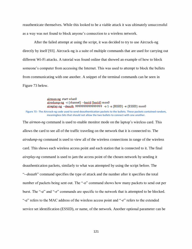
121
reauthenticate themselves. While this looked to be a viable attack it was ultimately unsuccessful
as a way was not found to block anyone’s connection to a wireless network.
After the failed attempt at using the script, it was decided to try to use Aircrack-ng
directly by itself [93]. Aircrack-ng is a suite of multiple commands that are used for carrying out
different Wi-Fi attacks. A tutorial was found online that showed an example of how to block
someone’s computer from accessing the Internet. This was used to attempt to block the bullets
from communicating with one another. A snippet of the terminal commands can be seen in
Figure 73 below.
Figure 73 - The Aircrack-ng code used to send deauthentication packets to the bullets. These packets contained random,
meaningless bits that should not allow the two bullets to connect with one another.
The airmon-ng command is used to enable monitor mode on the laptop’s wireless card. This
allows the card to see all of the traffic traveling on the network that it is connected to. The
airodump-ng command is used to view all of the wireless connections in range of the wireless
card. This shows each wireless access point and each station that is connected to it. The final
aireplay-ng command is used to jam the access point of the chosen network by sending it
deauthentication packets, similarly to what was attempted by using the script before. The
“--deauth” command specifies the type of attack and the number after it specifies the total
number of packets being sent out. The “-o” command shows how many packets to send out per
burst. The “-a” and “-e” commands are specific to the network that is attempted to be blocked.
“-a” refers to the MAC address of the wireless access point and “-e” refers to the extended
service set identification (ESSID), or name, of the network. Another optional parameter can be
122
added with “-c,” which is used to identify the MAC address of the computer that is being
targeted for jamming. This attack is typically more effective when adding this parameter.
This method was successfully used to jam a laptop’s connections to the Wi-Fi network it
was getting Internet access from. The computer did not have Internet access while the
deauthentication script was running and were able to access it as soon as the script was stopped.
After confirming that this worked correctly, the next step was to try and use it to jam
communications between the bullets. Initial attempts included trying to attack the bullets with the
laptop that it was connected to. This was due to the fact that a second computer with a wireless
card was not on hand. It was first tried to connect to the network created by the bullet acting as a
repeater. This network had the name, ubnt. It was thought that the bullets both connected to this
network to communicate with each other and sending the bullet connected to the Beagleboard
deauthentication packets would disrupt its communications. First, it was made sure that the
bullets were properly working by pinging them. Airodump-ng was then run to verify if the
computer could see the bullets as an access point and station. After seeing that this was the case,
aireplay-ng was run to send deauthentication packets to the bullet connected to the board. While
the packets were successfully sent the bullets were still able to communicate and send messages
to one another. It was then tried to jam the bullet acting as the repeater rather than the one acting
as the access point but the same result was obtained. After unsuccessfully running this, attack it
was briefly attempted to attack the bullets with other attacks that Aircrack-ng offered such as
fake authentication and fragmentation attacks. However these attacks were unsuccessful and
attempts were refocused on trying to compromise communications by jamming them.
After failing to jam the bullets by using the laptop that one of the bullets was connected
to a third laptop was used to conduct an attack. This was an example of a classic man-in-the-
123
middle attack where a person who is not supposed to be receiving information is able to hack
into the system. The same deauthentication attack as before was run but a glitch was
encountered. This glitch caused the computer’s wireless card to always look for networks on
channel -1, but no negative channels existed. To fix this a patch was downloaded that allowed for
the addition of the parameter, “ignore-negative-one.” This fixed the problems regarding this
glitch.
While running the man-in-middle attack a variety of settings were used that still proved
to be unsuccessful. The laptop would be connected to the ubnt network and was able to find the
bullets by running airodump-ng. Once this was completed, the jamming attack was tried again. It
was first tried to send deauthentication packets to the bullet connected to the Beagleboard. While
the packets were able to be sent the bullets were still able to communicate with one another. The
bullet connected to the laptop was then sent these packets but the attack was still was
unsuccessful. It was also attempted to add a parameter to specify the opposite bullet as the device
being targeted but communication between the bullets was still possible.
The next attack was composed of bridging the wireless card on the laptop connected to
the bullet with the laptop’s Ethernet port. The reason behind this was that the way the bullets
were previously set up they could only communicate between one another. This was because the
bullets acted as a wireless repeater. A repeater takes the signal of the network that it is plugged
into and creates a second network that extends the range of the original signal. This signal is
picked up by the second bullet and it then acts as an access point where multiple users can
connect to. In this case the bullet being plugged into the laptop was the repeater and the one
plugged into the Beagleboard was the access point. The repeater was taking the signal from the
Ethernet port and extending it so that the second bullet could connect to it. However no wireless
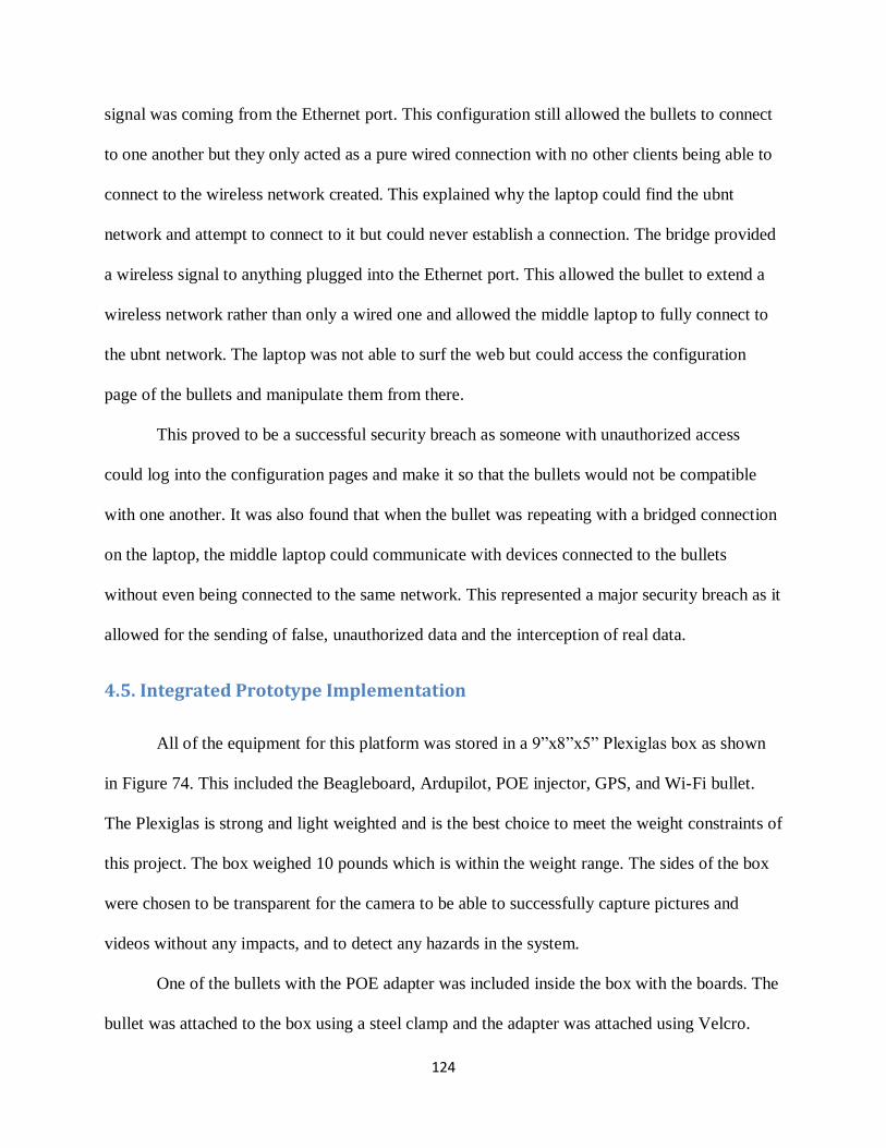
124
signal was coming from the Ethernet port. This configuration still allowed the bullets to connect
to one another but they only acted as a pure wired connection with no other clients being able to
connect to the wireless network created. This explained why the laptop could find the ubnt
network and attempt to connect to it but could never establish a connection. The bridge provided
a wireless signal to anything plugged into the Ethernet port. This allowed the bullet to extend a
wireless network rather than only a wired one and allowed the middle laptop to fully connect to
the ubnt network. The laptop was not able to surf the web but could access the configuration
page of the bullets and manipulate them from there.
This proved to be a successful security breach as someone with unauthorized access
could log into the configuration pages and make it so that the bullets would not be compatible
with one another. It was also found that when the bullet was repeating with a bridged connection
on the laptop, the middle laptop could communicate with devices connected to the bullets
without even being connected to the same network. This represented a major security breach as it
allowed for the sending of false, unauthorized data and the interception of real data.
4.5. Integrated Prototype Implementation
All of the equipment for this platform was stored in a 9”x8”x5” Plexiglas box as shown
in Figure 74. This included the Beagleboard, Ardupilot, POE injector, GPS, and Wi-Fi bullet.
The Plexiglas is strong and light weighted and is the best choice to meet the weight constraints of
this project. The box weighed 10 pounds which is within the weight range. The sides of the box
were chosen to be transparent for the camera to be able to successfully capture pictures and
videos without any impacts, and to detect any hazards in the system.
One of the bullets with the POE adapter was included inside the box with the boards. The
bullet was attached to the box using a steel clamp and the adapter was attached using Velcro.
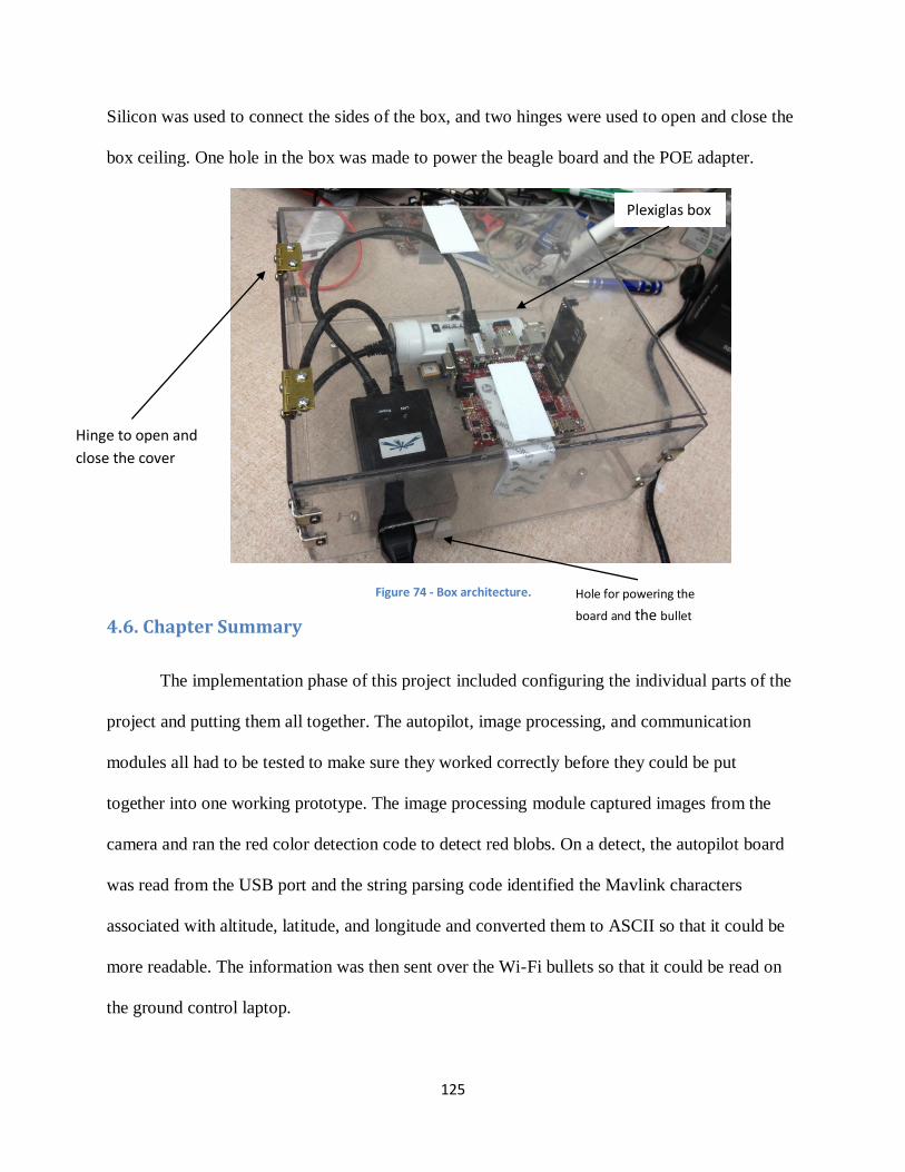
125
Silicon was used to connect the sides of the box, and two hinges were used to open and close the
box ceiling. One hole in the box was made to power the beagle board and the POE adapter.
Figure 74 - Box architecture.
4.6. Chapter Summary
The implementation phase of this project included configuring the individual parts of the
project and putting them all together. The autopilot, image processing, and communication
modules all had to be tested to make sure they worked correctly before they could be put
together into one working prototype. The image processing module captured images from the
camera and ran the red color detection code to detect red blobs. On a detect, the autopilot board
was read from the USB port and the string parsing code identified the Mavlink characters
associated with altitude, latitude, and longitude and converted them to ASCII so that it could be
more readable. The information was then sent over the Wi-Fi bullets so that it could be read on
the ground control laptop.
Plexiglas box
Hinge to open and
close the cover
Hole for powering the
board and the bullet

126
127
5. Results and Discussion
To verify that the platform was function correctly, tests had to be run to make sure that
the results intended were being obtained. This included testing all of the individual camera,
image processing, autopilot, and communications modules before integrating them into one
single product. Much was learned from these tests as to how the components functioned by
themselves and as a whole.
Additional analysis had to be performed on the results obtained from the attacks done on
the platform. The results acquired were not always the ones that were expected and therefore the
reasons for this had to be explored. It was crucial to understand exactly why everything
happened as it did in order to get a good understanding on the vulnerabilities of this platform and
how they could be exploited.
5.1. Platform Functionality
In order to make sure that this UAV platform was functioning as intended, tests were run
on the individual components as well as the final product. Tests had to be run on the image
processing module in order to make sure that the correct color and size were being detected and
on the autopilot to emphasize that the outputted data was accurate and reliable. Tests were
performed also to make sure that the wireless communication module was functioning properly
and could transmit messages as intended.
5.1.1. Image Processing Functionality
First and foremost, the system needed to be tested to see if the image processing
algorithm functioned successfully. The only way to do this was by displaying a processed image
and comparing it with the original. Since OpenCV does not support streaming video, this task
128
could only be done by repeatedly displaying an image using cvNamedWindow and
cvShowImage, waiting for a short time using cvWaitKey, and closing the image using
cvDestroyWindow. By doing these commands, the image would be presented chronologically as
a low frame-rate video. Although it was not advisable to introduce a delay inside the program as
it could affect the overall timing performance, it was only for the purpose of testing. In real time
testing, there was not a need for displaying the processed image so these functions could be
removed.
The items that had been used to test the image processing module were any regular red
colored objects. They were tested with various distances to make sure that the algorithm worked
correctly as was desired. In order to minimize errors, the platform was placed facing a complete
white wall so that other red objects could not be accidentally detected and produce unwanted
positive hits. Along with red colored objects, the platform was also tested with objects with other
colors like blue, orange, black. It needed to be ensured that the algorithm only detected red color
and rejected all other colors.
5.1.2. Socket Programming Functionality
The socket server code was included in the main code that was run on the Beagleboard
along with both the image processing and autopilot codes. After the camera detects red and the
autopilot outputs the desired data, all the information is available to the base station by running
the client code inside terminal of the base station. The Wi-Fi bullets must be connected to be able
to communicate between the two nodes successfully, as the Beagleboard and base stations are
two separated computers and connected via the ubnt wireless network. The server executed by
running the server code in the Beagleboard terminal followed by the IP address of the base
station (where the client code would be executed) and the port number which can be any number
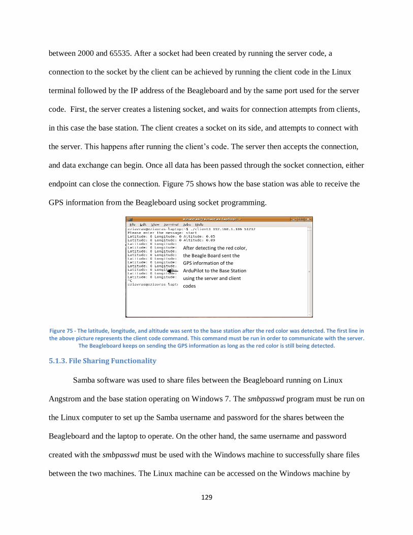
129
between 2000 and 65535. After a socket had been created by running the server code, a
connection to the socket by the client can be achieved by running the client code in the Linux
terminal followed by the IP address of the Beagleboard and by the same port used for the server
code. First, the server creates a listening socket, and waits for connection attempts from clients,
in this case the base station. The client creates a socket on its side, and attempts to connect with
the server. This happens after running the client’s code. The server then accepts the connection,
and data exchange can begin. Once all data has been passed through the socket connection, either
endpoint can close the connection. Figure 75 shows how the base station was able to receive the
GPS information from the Beagleboard using socket programming.
Figure 75 - The latitude, longitude, and altitude was sent to the base station after the red color was detected. The first line in the above picture represents the client code command. This command must be run in order to communicate with the server.
The Beagleboard keeps on sending the GPS information as long as the red color is still being detected.
5.1.3. File Sharing Functionality
Samba software was used to share files between the Beagleboard running on Linux
Angstrom and the base station operating on Windows 7. The smbpasswd program must be run on
the Linux computer to set up the Samba username and password for the shares between the
Beagleboard and the laptop to operate. On the other hand, the same username and password
created with the smbpasswd must be used with the Windows machine to successfully share files
between the two machines. The Linux machine can be accessed on the Windows machine by
After detecting the red color,
the Beagle Board sent the GPS information of the
ArduPilot to the Base Station
using the server and client
codes
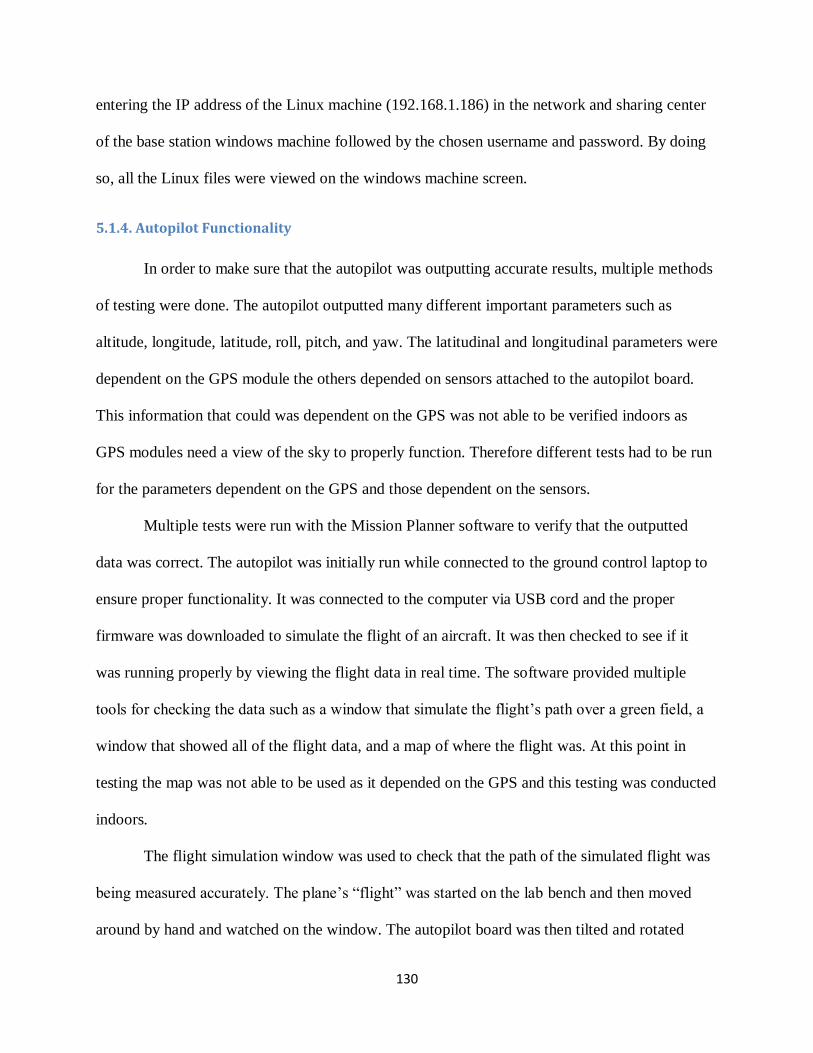
130
entering the IP address of the Linux machine (192.168.1.186) in the network and sharing center
of the base station windows machine followed by the chosen username and password. By doing
so, all the Linux files were viewed on the windows machine screen.
5.1.4. Autopilot Functionality
In order to make sure that the autopilot was outputting accurate results, multiple methods
of testing were done. The autopilot outputted many different important parameters such as
altitude, longitude, latitude, roll, pitch, and yaw. The latitudinal and longitudinal parameters were
dependent on the GPS module the others depended on sensors attached to the autopilot board.
This information that could was dependent on the GPS was not able to be verified indoors as
GPS modules need a view of the sky to properly function. Therefore different tests had to be run
for the parameters dependent on the GPS and those dependent on the sensors.
Multiple tests were run with the Mission Planner software to verify that the outputted
data was correct. The autopilot was initially run while connected to the ground control laptop to
ensure proper functionality. It was connected to the computer via USB cord and the proper
firmware was downloaded to simulate the flight of an aircraft. It was then checked to see if it
was running properly by viewing the flight data in real time. The software provided multiple
tools for checking the data such as a window that simulate the flight’s path over a green field, a
window that showed all of the flight data, and a map of where the flight was. At this point in
testing the map was not able to be used as it depended on the GPS and this testing was conducted
indoors.
The flight simulation window was used to check that the path of the simulated flight was
being measured accurately. The plane’s “flight” was started on the lab bench and then moved
around by hand and watched on the window. The autopilot board was then tilted and rotated
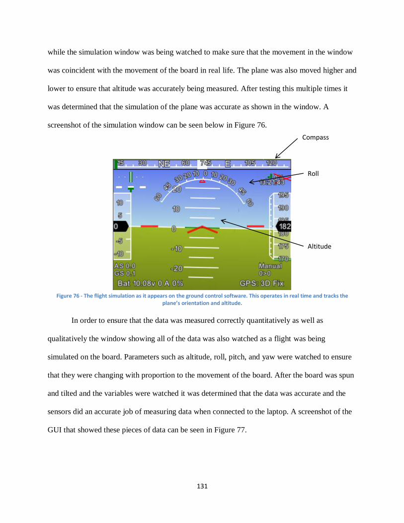
131
while the simulation window was being watched to make sure that the movement in the window
was coincident with the movement of the board in real life. The plane was also moved higher and
lower to ensure that altitude was accurately being measured. After testing this multiple times it
was determined that the simulation of the plane was accurate as shown in the window. A
screenshot of the simulation window can be seen below in Figure 76.
Figure 76 - The flight simulation as it appears on the ground control software. This operates in real time and tracks the
plane’s orientation and altitude.
In order to ensure that the data was measured correctly quantitatively as well as
qualitatively the window showing all of the data was also watched as a flight was being
simulated on the board. Parameters such as altitude, roll, pitch, and yaw were watched to ensure
that they were changing with proportion to the movement of the board. After the board was spun
and tilted and the variables were watched it was determined that the data was accurate and the
sensors did an accurate job of measuring data when connected to the laptop. A screenshot of the
GUI that showed these pieces of data can be seen in Figure 77.
Compass
Roll
Altitude
132
Figure 77 - Data window on the Mission Planner software. All important data is shown such as roll, pitch, yaw, latitude, and
longitude.
Once it was determined that the data was accurate when connected to the laptop, the
functionality of the board needed to be tested when connected to the Beagleboard. This was done
by connecting it to the Beagleboard via USB cable and outputting raw data from the USB port
into a text file. The type of language inside the text file was called Mavlink which is used in
autonomous vehicles. This language was coded in hexadecimal and by itself was not usable.
However it could be read by the ground control software and could recreate the flight. To first
test if this was functional the serial port of the Beagleboard was read and the resulting data was
copied to a Mavlog file. During the “flight” the board was twisted, raised, and lowered to ensure
that it could be recognized when viewing it through the software. The Mission Planner software
was then used to read the Mavlog file and the parameters were checked for accuracy in the same
way before, by watching the simulation and data windows. Later it was implemented on the
Beagleboard that the Mavlog file would be continuously written to and read by the software.
This also proved to be accurate and showed that it was possible to view the flight in real time,
albeit with a slight delay.
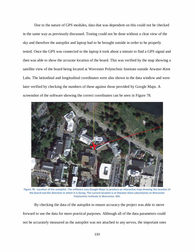
133
Due to the nature of GPS modules, data that was dependent on this could not be checked
in the same way as previously discussed. Testing could not be done without a clear view of the
sky and therefore the autopilot and laptop had to be brought outside in order to be properly
tested. Once the GPS was connected to the laptop it took about a minute to find a GPS signal and
then was able to show the accurate location of the board. This was verified by the map showing a
satellite view of the board being located at Worcester Polytechnic Institute outside Atwater-Kent
Labs. The latitudinal and longitudinal coordinates were also shown in the data window and were
later verified by checking the numbers of these against those provided by Google Maps. A
screenshot of the software showing the correct coordinates can be seen in Figure 78.
Figure 78 - Location of the autopilot. The software uses Google Maps to produce an interactive map showing the location of
the board and the direction in which it is facing. The current location is at Atwater-Kent Laboratories at Worcester Polytechnic Institute in Worcester, MA.
By checking the data of the autopilot to ensure accuracy the project was able to move
forward to use the data for more practical purposes. Although all of the data parameters could
not be accurately measured as the autopilot was not attached to any servos, the important ones
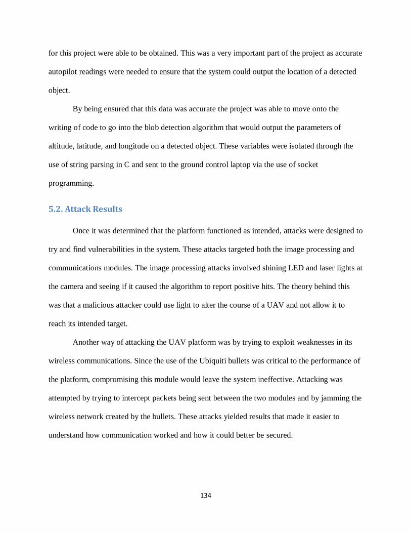
134
for this project were able to be obtained. This was a very important part of the project as accurate
autopilot readings were needed to ensure that the system could output the location of a detected
object.
By being ensured that this data was accurate the project was able to move onto the
writing of code to go into the blob detection algorithm that would output the parameters of
altitude, latitude, and longitude on a detected object. These variables were isolated through the
use of string parsing in C and sent to the ground control laptop via the use of socket
programming.
5.2. Attack Results
Once it was determined that the platform functioned as intended, attacks were designed to
try and find vulnerabilities in the system. These attacks targeted both the image processing and
communications modules. The image processing attacks involved shining LED and laser lights at
the camera and seeing if it caused the algorithm to report positive hits. The theory behind this
was that a malicious attacker could use light to alter the course of a UAV and not allow it to
reach its intended target.
Another way of attacking the UAV platform was by trying to exploit weaknesses in its
wireless communications. Since the use of the Ubiquiti bullets was critical to the performance of
the platform, compromising this module would leave the system ineffective. Attacking was
attempted by trying to intercept packets being sent between the two modules and by jamming the
wireless network created by the bullets. These attacks yielded results that made it easier to
understand how communication worked and how it could better be secured.
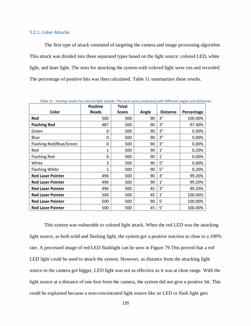
135
5.2.1. Color Attacks
The first type of attack consisted of targeting the camera and image processing algorithm.
This attack was divided into three separated types based on the light source: colored LED, white
light, and laser light. The tests for attacking the system with colored light were run and recorded.
The percentage of positive hits was then calculated. Table 11 summarizes these results.
Table 11 - Testing results for colored light attacks. The tests were conducted with different angles and distances.
Color Positive Reads
Total Scans Angle Distance Percentage
Red 500 500 90 3" 100.00%
Flashing Red 487 500 90 3" 97.40%
Green 0 500 90 3" 0.00%
Blue 0 500 90 3" 0.00%
Flashing Red/Blue/Green 0 500 90 3" 0.00%
Red 1 500 90 1' 0.20%
Flashing Red 0 500 90 1' 0.00%
White 3 500 90 5" 0.60%
Flashing White 1 500 90 5" 0.20%
Red Laser Pointer 496 500 90 3" 99.20%
Red Laser Pointer 496 500 90 1' 99.20%
Red Laser Pointer 496 500 45 3" 99.20%
Red Laser Pointer 500 500 45 1' 100.00%
Red Laser Pointer 500 500 90 5' 100.00%
Red Laser Pointer 500 500 45 5' 100.00%
This system was vulnerable to colored light attack. When the red LED was the attacking
light source, as both solid and flashing light, the system got a positive reaction at close to a 100%
rate. A processed image of red LED flashlight can be seen in Figure 79.This proved that a red
LED light could be used to attack the system. However, as distance from the attacking light
source to the camera got bigger, LED light was not as effective as it was at close range. With the
light source at a distance of one foot from the camera, the system did not give a positive hit. This
could be explained because a non-concentrated light source like an LED or flash light gets
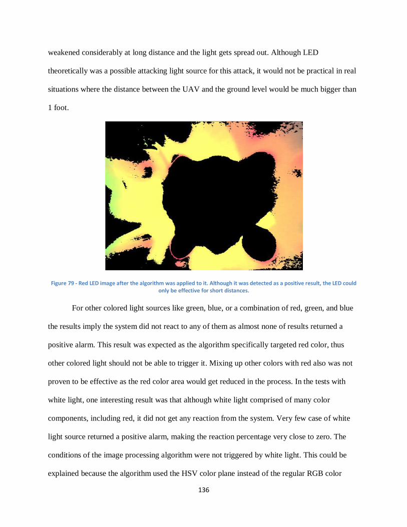
136
weakened considerably at long distance and the light gets spread out. Although LED
theoretically was a possible attacking light source for this attack, it would not be practical in real
situations where the distance between the UAV and the ground level would be much bigger than
1 foot.
Figure 79 - Red LED image after the algorithm was applied to it. Although it was detected as a positive result, the LED could only be effective for short distances.
For other colored light sources like green, blue, or a combination of red, green, and blue
the results imply the system did not react to any of them as almost none of results returned a
positive alarm. This result was expected as the algorithm specifically targeted red color, thus
other colored light should not be able to trigger it. Mixing up other colors with red also was not
proven to be effective as the red color area would get reduced in the process. In the tests with
white light, one interesting result was that although white light comprised of many color
components, including red, it did not get any reaction from the system. Very few case of white
light source returned a positive alarm, making the reaction percentage very close to zero. The
conditions of the image processing algorithm were not triggered by white light. This could be
explained because the algorithm used the HSV color plane instead of the regular RGB color
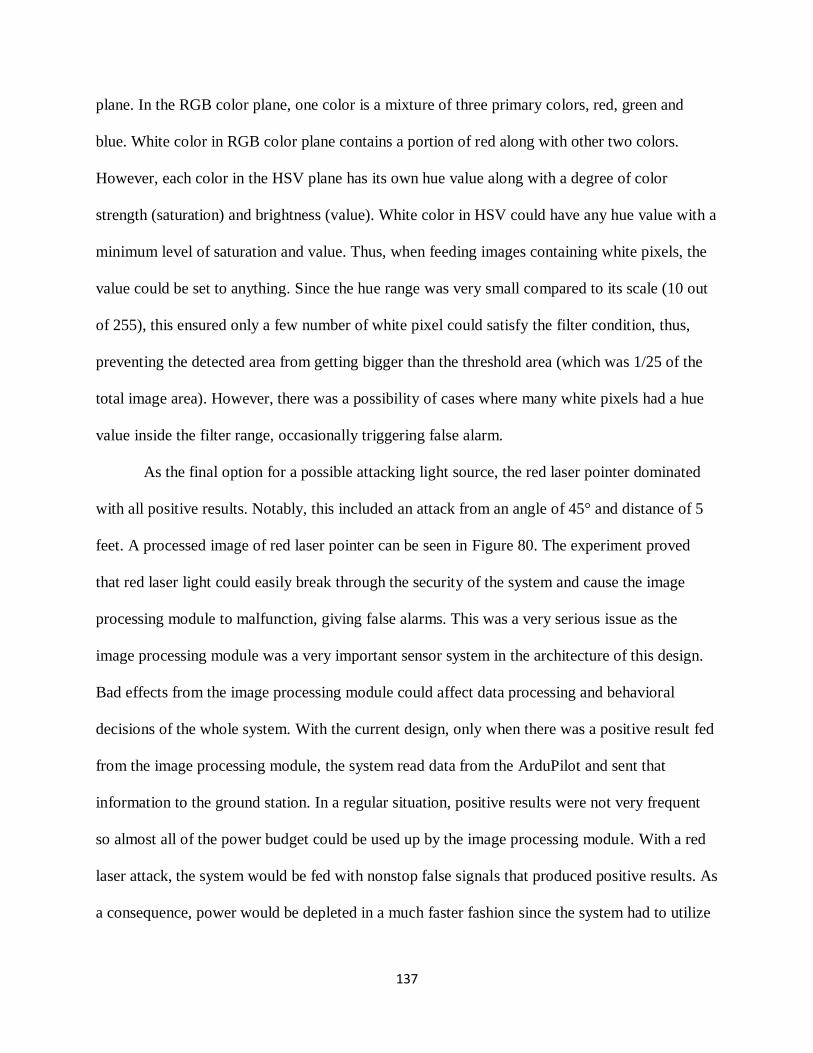
137
plane. In the RGB color plane, one color is a mixture of three primary colors, red, green and
blue. White color in RGB color plane contains a portion of red along with other two colors.
However, each color in the HSV plane has its own hue value along with a degree of color
strength (saturation) and brightness (value). White color in HSV could have any hue value with a
minimum level of saturation and value. Thus, when feeding images containing white pixels, the
value could be set to anything. Since the hue range was very small compared to its scale (10 out
of 255), this ensured only a few number of white pixel could satisfy the filter condition, thus,
preventing the detected area from getting bigger than the threshold area (which was 1/25 of the
total image area). However, there was a possibility of cases where many white pixels had a hue
value inside the filter range, occasionally triggering false alarm.
As the final option for a possible attacking light source, the red laser pointer dominated
with all positive results. Notably, this included an attack from an angle of 45° and distance of 5
feet. A processed image of red laser pointer can be seen in Figure 80. The experiment proved
that red laser light could easily break through the security of the system and cause the image
processing module to malfunction, giving false alarms. This was a very serious issue as the
image processing module was a very important sensor system in the architecture of this design.
Bad effects from the image processing module could affect data processing and behavioral
decisions of the whole system. With the current design, only when there was a positive result fed
from the image processing module, the system read data from the ArduPilot and sent that
information to the ground station. In a regular situation, positive results were not very frequent
so almost all of the power budget could be used up by the image processing module. With a red
laser attack, the system would be fed with nonstop false signals that produced positive results. As
a consequence, power would be depleted in a much faster fashion since the system had to utilize
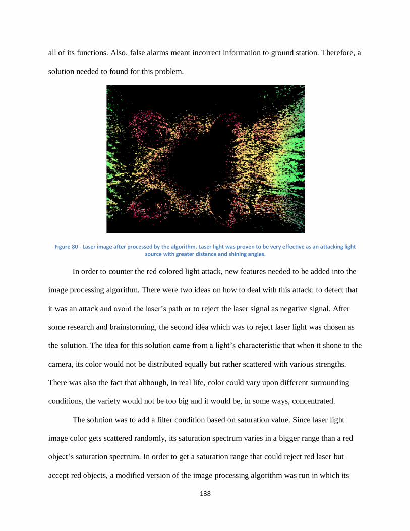
138
all of its functions. Also, false alarms meant incorrect information to ground station. Therefore, a
solution needed to found for this problem.
Figure 80 - Laser image after processed by the algorithm. Laser light was proven to be very effective as an attacking light source with greater distance and shining angles.
In order to counter the red colored light attack, new features needed to be added into the
image processing algorithm. There were two ideas on how to deal with this attack: to detect that
it was an attack and avoid the laser’s path or to reject the laser signal as negative signal. After
some research and brainstorming, the second idea which was to reject laser light was chosen as
the solution. The idea for this solution came from a light’s characteristic that when it shone to the
camera, its color would not be distributed equally but rather scattered with various strengths.
There was also the fact that although, in real life, color could vary upon different surrounding
conditions, the variety would not be too big and it would be, in some ways, concentrated.
The solution was to add a filter condition based on saturation value. Since laser light
image color gets scattered randomly, its saturation spectrum varies in a bigger range than a red
object’s saturation spectrum. In order to get a saturation range that could reject red laser but
accept red objects, a modified version of the image processing algorithm was run in which its
139
saturation range was increased by 10 from 0 to 260. As expected, only small parts of laser light
image could pass through in each saturation range like demonstrated in Figure 81. The saturation
range detected red objects most was 250 to 260. In this range, the detected area of laser light got
decreased dramatically, thus, the system could reject laser light as a negative signal but still
accept red objects. Coincidentally, this method could also filter out rare case of white light that
occasionally gave a false alarm as mentioned before. Since white color in the HSV color plane
had minimum level of saturation, it could not satisfy the saturation condition.
Although the additional saturation condition was simple, it was very effective with
rejecting laser light. With a new version of the image processing algorithm, the system still
worked stably but no longer got false alarms caused by the laser light.
Figure 81 - Laser light after the saturation filter is applied to it. The area of detected pixels had been reduced greatly, making laser light no longer a threat to the algorithm.
However, one downside of the new algorithm was the system only got defended
passively through a saturation filter “shield”. Thus, the system could not take any action to avoid
the attack. This was the second counter measurement idea, to detect the attack and avoid it. One
idea was to measure the density of filtered pixels. For red laser pointer light, the pixels got
140
scattered in the image while filtered pixels of regular red object focused on one area where the
object was. With the ability to detect attacks, the UAV could take intelligent behavior to avoid
the attack source. For instance, the UAV could turn around when there was an attack detected,
preventing continuous attacks. Unfortunately, the time and resource budget did not
implementation of this idea since it would require much more programming.
5.2.2. Wireless Attacks
Wireless attacks were run to try to compromise the communications module of the UAV
platform. Multiple methods were tested including trying to intercept packets being sent between
the Beagleboard and ground station using Wireshark and trying to jam the network of the bullets.
These tests provided mixed results as it was possible to find some vulnerabilities in the system
but some other attacks did not execute as expected.
5.2.2.1. Wireshark Results
A third laptop was used to intercept the packets being sent from the Beagleboard to the
base station. The top panel of the Wireshark window identifies each packet’s source and
destination nodes, protocol implemented, and information about each packet as shown in Figure
82. By selecting a specific packet, many details can be displayed about this specific one. The
packets captured can be filtered by entering the IP address of the desired packets in the search
box. Display filters allow concentrating only on the packets of interest. The desired packets are
the packets that include the Wi-Fi bullets IP addresses. The middle panel displays information
about the data of the specified packets, and a specific field of the packet can be chosen such as
the duration field.
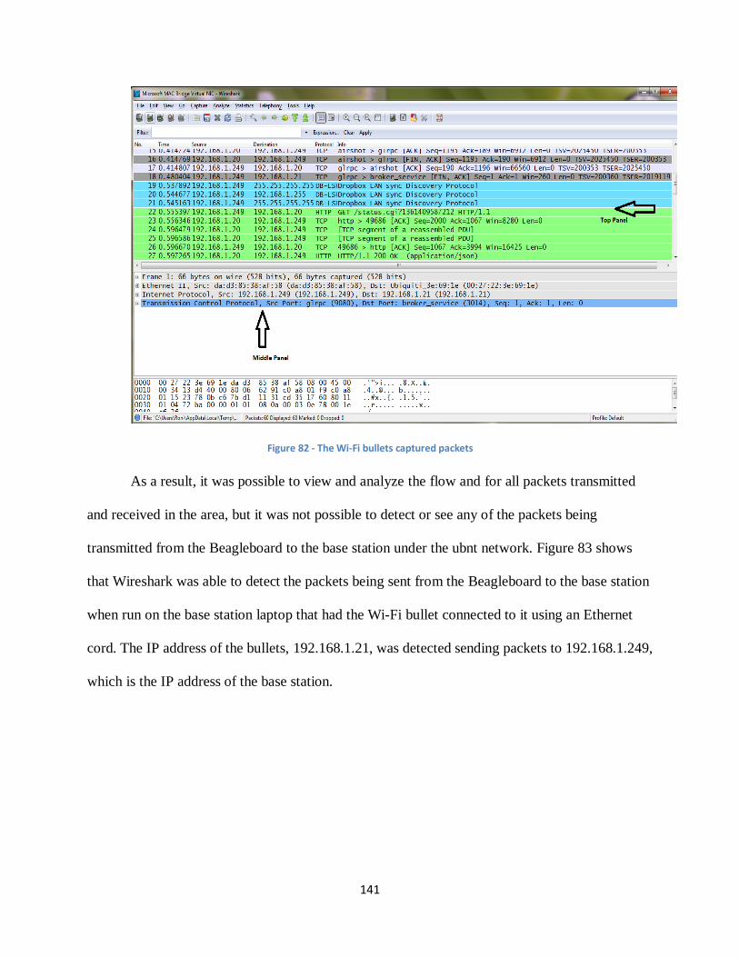
141
Figure 82 - The Wi-Fi bullets captured packets
As a result, it was possible to view and analyze the flow and for all packets transmitted
and received in the area, but it was not possible to detect or see any of the packets being
transmitted from the Beagleboard to the base station under the ubnt network. Figure 83 shows
that Wireshark was able to detect the packets being sent from the Beagleboard to the base station
when run on the base station laptop that had the Wi-Fi bullet connected to it using an Ethernet
cord. The IP address of the bullets, 192.168.1.21, was detected sending packets to 192.168.1.249,
which is the IP address of the base station.
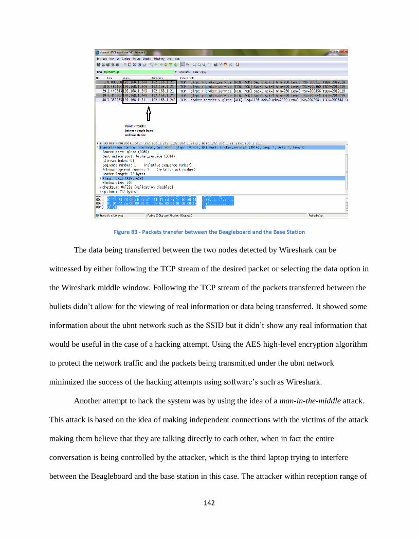
142
Figure 83 - Packets transfer between the Beagleboard and the Base Station
The data being transferred between the two nodes detected by Wireshark can be
witnessed by either following the TCP stream of the desired packet or selecting the data option in
the Wireshark middle window. Following the TCP stream of the packets transferred between the
bullets didn’t allow for the viewing of real information or data being transferred. It showed some
information about the ubnt network such as the SSID but it didn’t show any real information that
would be useful in the case of a hacking attempt. Using the AES high-level encryption algorithm
to protect the network traffic and the packets being transmitted under the ubnt network
minimized the success of the hacking attempts using software’s such as Wireshark.
Another attempt to hack the system was by using the idea of a man-in-the-middle attack.
This attack is based on the idea of making independent connections with the victims of the attack
making them believe that they are talking directly to each other, when in fact the entire
conversation is being controlled by the attacker, which is the third laptop trying to interfere
between the Beagleboard and the base station in this case. The attacker within reception range of
143
an unencrypted Wi-Fi access point can insert himself as a man-in-the-middle by redirecting all
packets through an “evil twin,” which is a Wi-Fi access point that appears to be a legitimate, but
actually has been set up to eavesdrop on wireless communications. The attacker can then log
onto the real server using victim-supplied information, capturing all messages exchanged
between the user and real server [94]. This attempt to hack the system failed gain. In order for
the man-in-the-middle attack attempt to work, the wireless network used must be unsecured or
secured using some low level security algorithm. This system’s security algorithm is an up to
date high class AES encryption algorithm, which makes a man-in-the-middle attack real hard to
execute.
5.2.2.2. Aircrack-ng Results
The second attempt at compromising the wireless communications dealt with using the
Aircrack-ng suite. This suite included multiple commands that allowed the bullets to be attacked
in multiple ways. Ways to compromise included deauthenication, fake authentication,
fragmentation attacks, and interactive packet replays.
The attack that the most time was spent on was attempting to jam the communications
between the bullets by sending deauthentication packets to one of them. The idea behind this was
to bombard the bullet creating the new network with packets so that it could not create a new
network that the bullet connected to the Beagleboard could connect with. The first attempt at
sending jamming packets involved trying to jam a laptop from connecting to the Internet. This
was successfully done by sending packets to the access point of that laptop’s Internet connection
and not allowing the client laptop to connect to it. This verified that the deauthentications
commands worked and could be used to jam a connection.
144
Once it was verified that this command work it was then attempted to jam the Wi-Fi
bullets. At first this was tried with the bullet acting as the repeater connected to the Ethernet port
of the laptop without any bridging involved with the wireless card. The bullet acting as the
access point was also connected to the Beagleboard via Ethernet port so that it was picking up
the signals sent out by the bullet connected to the laptop. Using this configuration, a jamming
attack was programmed to block all clients trying to connect to the repeater bullet. While these
jamming packets were able to be sent out successfully, the two bullets still were able to
communicate with each other.
The initial reasoning for these bullets not being able to be jammed was that the repeater
was not extending a wireless network. The bullet was connected to an Ethernet port of network
type Local Area Network (LAN). This was a wired network that could not be connected to
wirelessly except through another Ubiquiti bullet with the correct configuration. The device that
the bullet was connected to, in this case the Beagleboard, could communicate with the other
bullet but no other device could connect to it. Although the bullet was configured as an access
point no other device with a wireless card could connect to it. It could be seen by other devices
with wireless cards such as a laptop but it was not able to establish a solid connection. A middle
laptop could briefly connect and see the bullet and its BSSID number but it could only see it for
a few seconds before the connection was lost. The deauthentication packets were sent to the
wireless access point while the laptop was connected to the repeater’s network but were not
effective.
The next step taken in the hacking of the bullets was to bridge the ground control laptop’s
LAN and wireless network connections. This allowed the Ethernet port and wireless card to
share the same connection and the Ethernet port to output the laptop’s wireless connection. The
145
laptop in essence was configured to act as a wireless router, getting its Internet signal through the
wireless card and outputting it through the Ethernet port. This allowed the bullet acting as a
repeater to output a wireless network and allow other devices to connect to the access point.
Bridging the laptop’s connections allowed a third laptop to establish a connection to the
created network and allow us to perform man-in-the-middle-attacks. The third laptop was
successfully able to connect to the ubnt wireless network and fully communicate with the bullets
and Beagleboard. This was verified by pinging all three of these devices from the middle laptop
and receiving a response from each one. This functionality opened up the device to multiple
man-in-the-middle attacks.
The first attack dealt with logging into the configuration page for the bullets. By
connecting to the ubnt network it was possible to access the configuration page by typing in the
IP address of each bullet into the address bar of an online browser. As long as the attacker knew
the username and password for each bullet he could be able to switch the configuration of the
bullets so that it would not act as a repeater, make it so that the two bullets were not authorized
to talk to one another, or enable certain settings that did not allow them to work within the
context of this project at all. This was a very prominent concern as having the proper settings
allowed the laptop and board to communicate with one another and send vital information back
and forth.
The second attack dealt with accessing the socket programming that allowed the bullets
to communicate with one another. The plan was to use the middle laptop to intercept the
messages being sent to the ground control laptop that contained the location of a detected object.
This was going to be done via MAC spoofing. The bullets were configured to only communicate
between each other by specifying the specific MAC address of each one. It was thought that by
146
making the MAC address of the wireless card of the attacking laptop the same as the address of
the bullet acting as the repeater the bullet connected to the Beagleboard could be fooled into
thinking that the laptop was the bullet and send messages to it. Switching the MAC address of a
laptop in Linux is very simple and only requires three lines of commands.
It was found that the attacking laptop could communicate with the Beagleboard
regardless of its MAC address and whether it was connected to the ubnt network. While the
laptop had to be connected to the ubnt network to access the configuration page of the bullets, it
could communicate with any of the bullets or Beagleboard regardless of which network it was
connected to. This was verified by pinging the board and bullets and using the server and client
codes to send messages back and forth. This presented a major security concern as it would
allow anyone with a wireless card and the proper codes to initialize the image processing
algorithm. This would send the coordinates of a detected object to the attacking laptop rather
than the ground control laptop and compromise the entire operation.
The third attack was trying to jam the bullets while the connection was bridged on the
ground control laptop. It was thought that since the repeater bullet was now extending a wireless
signal the wireless deauthentication packets would be able to successfully jam communications
and not allow the bullet acting as an access point to connect to the repeater. Packets were
attempted to be sent out in the same ways as before but still were not successful in jamming
communications. The bullets could still communicate while the jamming was being done. It is
thought that the reason for this is because the signals sent between the repeater and access point
are not the same as those between access point and client. It is possible that this connection uses
a different standard and therefore is not affected in the same way.
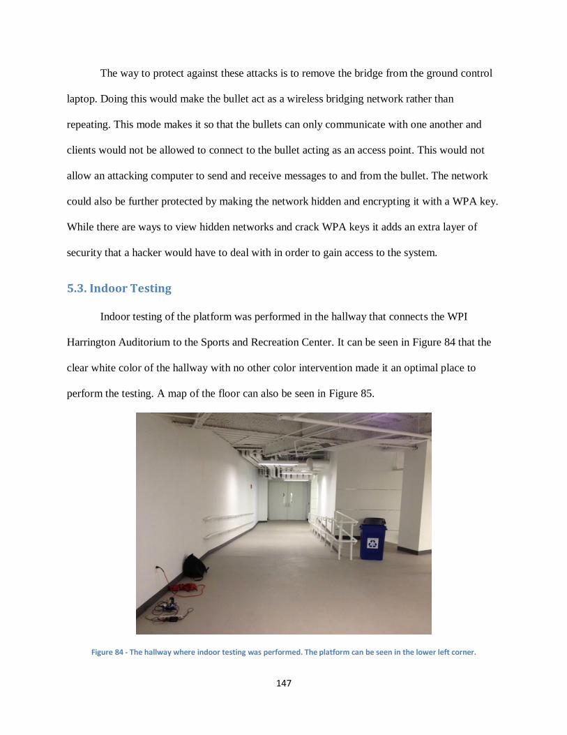
147
The way to protect against these attacks is to remove the bridge from the ground control
laptop. Doing this would make the bullet act as a wireless bridging network rather than
repeating. This mode makes it so that the bullets can only communicate with one another and
clients would not be allowed to connect to the bullet acting as an access point. This would not
allow an attacking computer to send and receive messages to and from the bullet. The network
could also be further protected by making the network hidden and encrypting it with a WPA key.
While there are ways to view hidden networks and crack WPA keys it adds an extra layer of
security that a hacker would have to deal with in order to gain access to the system.
5.3. Indoor Testing
Indoor testing of the platform was performed in the hallway that connects the WPI
Harrington Auditorium to the Sports and Recreation Center. It can be seen in Figure 84 that the
clear white color of the hallway with no other color intervention made it an optimal place to
perform the testing. A map of the floor can also be seen in Figure 85.
Figure 84 - The hallway where indoor testing was performed. The platform can be seen in the lower left corner.
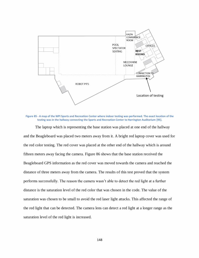
148
Figure 85 - A map of the WPI Sports and Recreation Center where indoor testing was performed. The exact location of the testing was in the hallway connecting the Sports and Recreation Center to Harrington Auditorium [95].
The laptop which is representing the base station was placed at one end of the hallway
and the Beagleboard was placed two meters away from it. A bright red laptop cover was used for
the red color testing. The red cover was placed at the other end of the hallway which is around
fifteen meters away facing the camera. Figure 86 shows that the base station received the
Beagleboard GPS information as the red cover was moved towards the camera and reached the
distance of three meters away from the camera. The results of this test proved that the system
performs successfully. The reason the camera wasn’t able to detect the red light at a further
distance is the saturation level of the red color that was chosen in the code. The value of the
saturation was chosen to be small to avoid the red laser light attacks. This affected the range of
the red light that can be detected. The camera lens can detect a red light at a longer range as the
saturation level of the red light is increased.
Location of testing
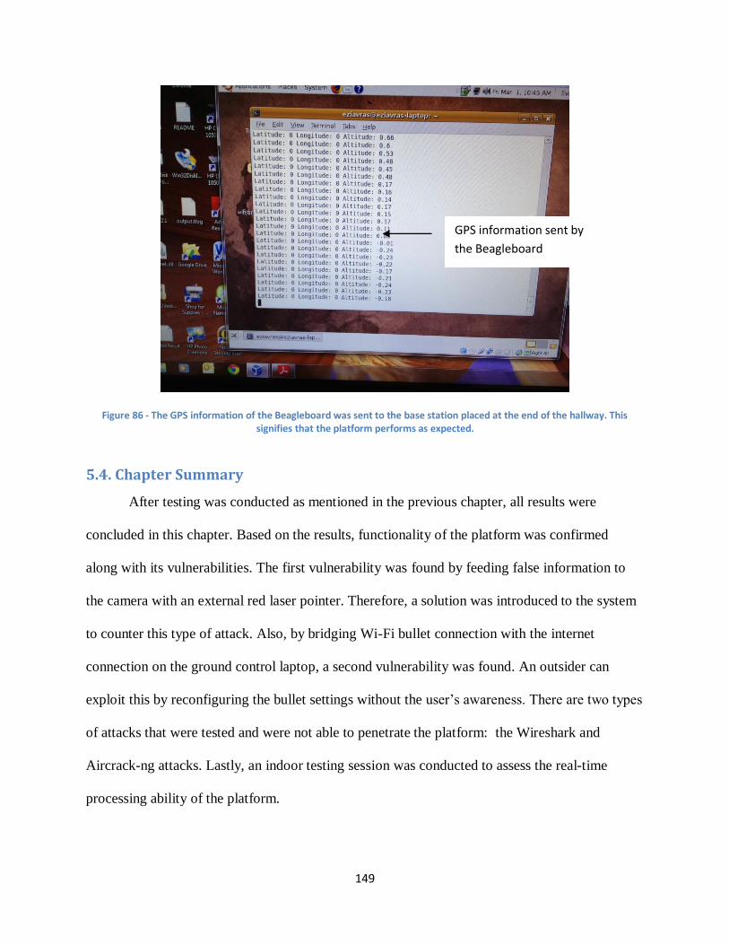
149
Figure 86 - The GPS information of the Beagleboard was sent to the base station placed at the end of the hallway. This signifies that the platform performs as expected.
5.4. Chapter Summary
After testing was conducted as mentioned in the previous chapter, all results were
concluded in this chapter. Based on the results, functionality of the platform was confirmed
along with its vulnerabilities. The first vulnerability was found by feeding false information to
the camera with an external red laser pointer. Therefore, a solution was introduced to the system
to counter this type of attack. Also, by bridging Wi-Fi bullet connection with the internet
connection on the ground control laptop, a second vulnerability was found. An outsider can
exploit this by reconfiguring the bullet settings without the user’s awareness. There are two types
of attacks that were tested and were not able to penetrate the platform: the Wireshark and
Aircrack-ng attacks. Lastly, an indoor testing session was conducted to assess the real-time
processing ability of the platform.
GPS information sent by
the Beagleboard
150
6. Conclusions and Future Recommendations
With all the tests conducted and results discussed, this final chapter concludes everything
in the report. This chapter summarizes key ideas on the importance of this project, how it was
done, and major knowledge that has been gained over the course of the project. Also, due to
several constraints in both time and resources, much room for improvement exists. Thus,
difficulties and limitations of the implementation process are listed along with possible
recommendations that could be done in future.
6.1. Conclusions
Over the course of this project, much was learned regarding modern-day UAVs and
security of their computer architecture. UAVs consist of multiple modules that are each
responsible for performing a different function. These typically include image processing, central
processing on a computer board, a camera, communications module, autopilot module, and a
ground control module. All of these must be programmed to fit together to ensure that the UAV
is fully functional and completes all of its tasks properly.
Sizing is also a very important factor in the design of UAV platforms. Since these planes
are unmanned, they are typically smaller than most man-flown aircraft. While some military-
grade planes can carry a big payload, most are used for civil uses and have limited size, space,
and power capacity. For this reason one must be careful when designing a platform so that they
do not exceed the limitations of the actual aircraft.
There were many lessons that were learned regarding the design of aUAV computer
architecture. The Beagleboard was an ideal board to use as the central processing unit for this
project as it had the USB, Ethernet, and camera port interfaces required to connect the autopilot,
Wi-Fi bullet, and camera. It was also a very compact board capable of running a full version of
151
Linux which made it easy to write and compile software to complete the necessary tasks for this
project. The board also had the advantage of having ample memory to run all of the necessary
tasks of this project. This also featured internal as well as external memory that could be stored
on a secure digital card. This allows a user to select a card to use that will have enough memory
to store his or her data.
Communication played a vital role in the functionality and security of this platform. It
was determined that Wi-Fi was the best way to transfer data wirelessly from board to ground
station as it is very powerful and has a variety of security options. Flaws were found in the
security however that left the platform susceptible to malicious attacks. Configuring the Wi-Fi
settings the wrong way or leaving the network unencrypted could have disastrous results as a
unauthorized user can either shut down communication between the modules or intercept data
that is only meant to be seen by the board and ground station. Another important aspect of the
communications methods used was the interface through which the ground station and platform
talked to one another. Socket programming was utilized in this project so that the ground control
user could open a simple Linux terminal, run a program, and start the image processing
algorithm remotely. Messages were able to be sent via a user-defined port on the Beagleboard
and two-way communication was possible. The algorithm would start to run on the UAV
platform and report the results directly back to the terminal on the user’s side. This made for a
very simple, streamlined interface through which the laptop could wirelessly transmit commands
to the Beagleboard and the board would transmit back the results of its search.
This project also dealt heavily with how computers process image processing. It was
conclude that HSV is the ideal color scheme to utilize when trying to recognize colors as it
focuses on shade as well as base color. This made it easy to filter out high-intensity light that
152
would probably be an attacker trying to compromise the image processing of the system. An
algorithm was that depended on certain color and size of an object. A color could be specified
using the HSV parameters and the size was specified as a ratio of the number of pixels where the
color was detected. The camera would take in all of the images around it, process them on the
algorithm, and output results of its location if a positive hit was detected. While this algorithm
could have been more advanced and sophisticated, it met the needs of this project.
Much was also learned about the vulnerabilities associated with UAV systems. During
the course of this project attacks were taken that targeted the image processing and
communications modules of the platform. The attacks and their associated results gave good
insight as to how the modules themselves work and how a potential enemy could take advantage
of them to compromise its functionality. Color attacks were used to either blind the camera so
that it read nothing or made it report positives on items that it should not have. This attack was
countered by adjusting the values of the color parameters for which to report a positive hit. The
communications were attacked by trying to intercept the wireless packets sent between the
modules, jamming the Wi-Fi network, and connecting to the network so that data could be
accessed. Wireshark was used to intercept packets and Aircrack-ng was used to jam the network.
While the first two attacks were not able to compromise the system, it was found that it was
possible for an unauthenticated user to communicate with the Beagleboard.
6.2. Future Work
In this MQP a module was created for future teams to base their MQPs on. The team was
able to develop a platform, and was able to figure out two counter measures for two possible
embedded attacks. Future MQP teams can continue the progress in developing more computers
153
embedded attacks and find some counter measures for them. Future work on this project should
also include:
Improving the image processing and the blob detection algorithm. The team was able to
develop a fully functional algorithm that detects the red. Blobs appear in different ways
depending on their scale after the red color is detected. This system is meant to be
embedded in UAV’s and other advanced, data-dependent aircraft of the future for search
and rescue missions. Future teams can develop some more advanced algorithms with
sensors more sensitive to human bodies (such as detecting the body temperature of a
human being or human motion sensor).
Implementing a more active method to counter against color light attack. Right now, the
system was only defended passively by rejecting a red laser signal. However, although
the red laser light could no longer produce a positive result from the image processing
module, the light could easily cover all of the camera image area, blinding the system. As
long as there was laser light shone to the camera, it would still be disabled. Thus, one
possible improvement the system could get is a more efficient algorithm that can detect
when there is an attack. Furthermore, the central computing unit should be able to take
some action like avoiding laser light or alarm base station about the attack.
Finding an alternative to the Wi-Fi bullets. The 802.11N multi-function wireless platform
bullets that were used are capable of wireless speeds up to 100Mbps which is more than
enough for the project’s wireless purposes. The bullets create a safe network to share the
information. Configuring the bullets right wireless and networking settings was tough and
required a decent knowledge of the principles of communication and networking. Many
other alternatives are easier to deal with.
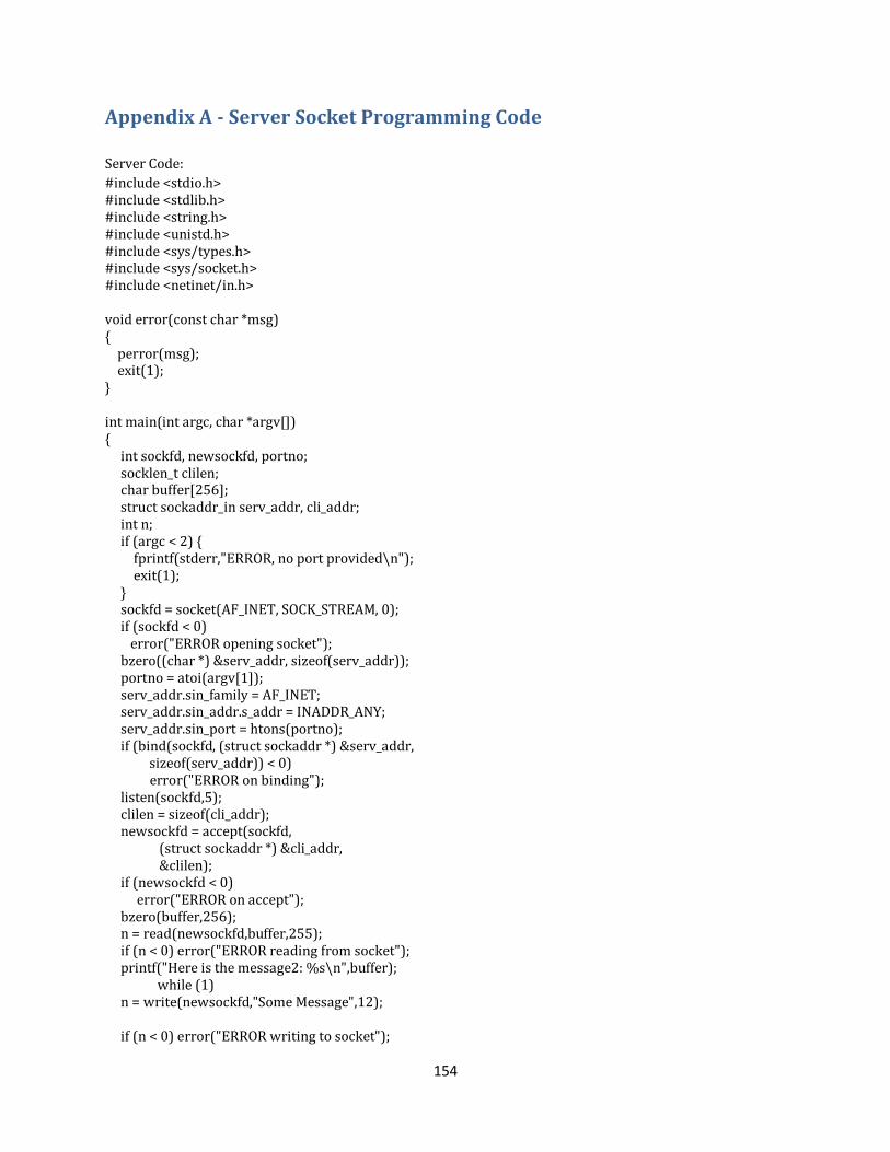
154
Appendix A - Server Socket Programming Code
Server Code:
#include <stdio.h> #include <stdlib.h> #include <string.h> #include <unistd.h> #include <sys/types.h> #include <sys/socket.h> #include <netinet/in.h> void error(const char *msg) { perror(msg); exit(1); } int main(int argc, char *argv[]) { int sockfd, newsockfd, portno; socklen_t clilen; char buffer[256]; struct sockaddr_in serv_addr, cli_addr; int n; if (argc < 2) { fprintf(stderr,"ERROR, no port provided\n"); exit(1); } sockfd = socket(AF_INET, SOCK_STREAM, 0); if (sockfd < 0) error("ERROR opening socket"); bzero((char *) &serv_addr, sizeof(serv_addr)); portno = atoi(argv[1]); serv_addr.sin_family = AF_INET; serv_addr.sin_addr.s_addr = INADDR_ANY; serv_addr.sin_port = htons(portno); if (bind(sockfd, (struct sockaddr *) &serv_addr, sizeof(serv_addr)) < 0) error("ERROR on binding"); listen(sockfd,5); clilen = sizeof(cli_addr); newsockfd = accept(sockfd, (struct sockaddr *) &cli_addr, &clilen); if (newsockfd < 0) error("ERROR on accept"); bzero(buffer,256); n = read(newsockfd,buffer,255); if (n < 0) error("ERROR reading from socket"); printf("Here is the message2: %s\n",buffer); while (1) n = write(newsockfd,"Some Message",12); if (n < 0) error("ERROR writing to socket");

155
close(newsockfd); close(sockfd); return 0; }
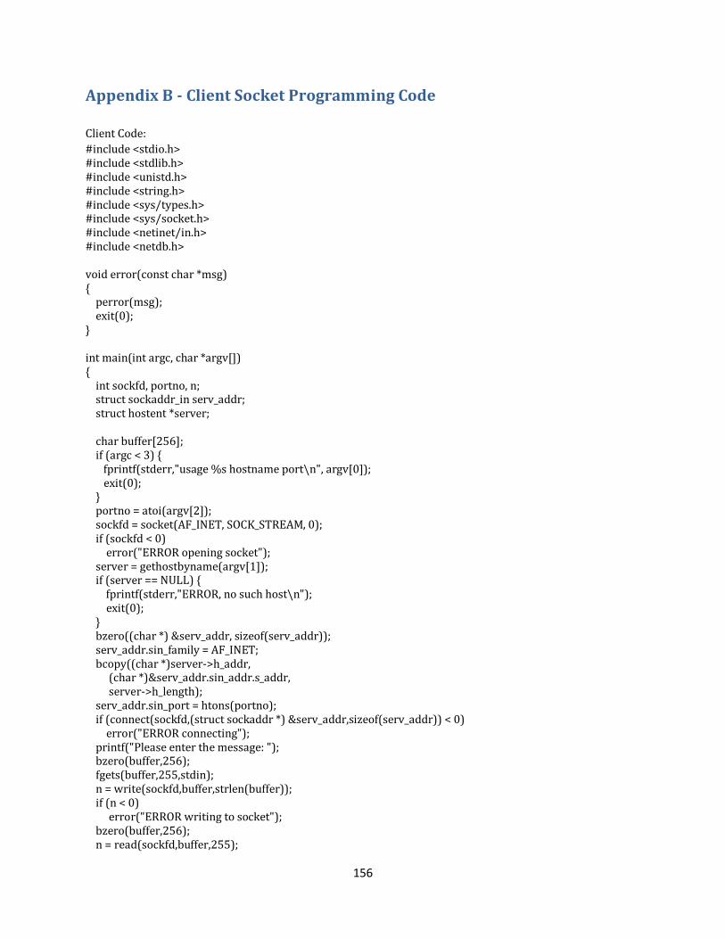
156
Appendix B - Client Socket Programming Code
Client Code:
#include <stdio.h> #include <stdlib.h> #include <unistd.h> #include <string.h> #include <sys/types.h> #include <sys/socket.h> #include <netinet/in.h> #include <netdb.h> void error(const char *msg) { perror(msg); exit(0); } int main(int argc, char *argv[]) { int sockfd, portno, n; struct sockaddr_in serv_addr; struct hostent *server; char buffer[256]; if (argc < 3) { fprintf(stderr,"usage %s hostname port\n", argv[0]); exit(0); } portno = atoi(argv[2]); sockfd = socket(AF_INET, SOCK_STREAM, 0); if (sockfd < 0) error("ERROR opening socket"); server = gethostbyname(argv[1]); if (server == NULL) { fprintf(stderr,"ERROR, no such host\n"); exit(0); } bzero((char *) &serv_addr, sizeof(serv_addr)); serv_addr.sin_family = AF_INET; bcopy((char *)server->h_addr, (char *)&serv_addr.sin_addr.s_addr, server->h_length); serv_addr.sin_port = htons(portno); if (connect(sockfd,(struct sockaddr *) &serv_addr,sizeof(serv_addr)) < 0) error("ERROR connecting"); printf("Please enter the message: "); bzero(buffer,256); fgets(buffer,255,stdin); n = write(sockfd,buffer,strlen(buffer)); if (n < 0) error("ERROR writing to socket"); bzero(buffer,256); n = read(sockfd,buffer,255);
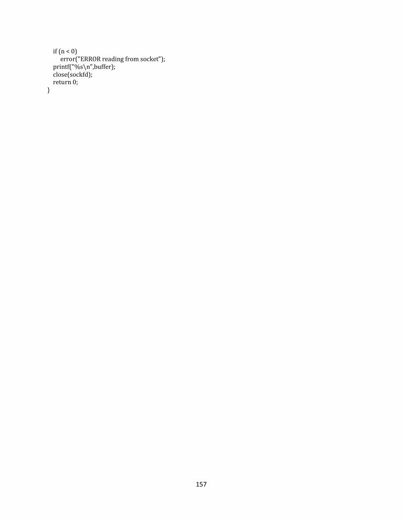
157
if (n < 0) error("ERROR reading from socket"); printf("%s\n",buffer); close(sockfd); return 0; }
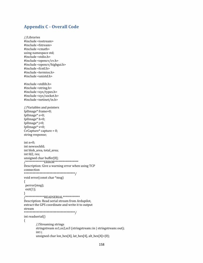
158
Appendix C - Overall Code
//Libraries #include <iostream> #include <fstream> #include <cmath> using namespace std; #include <stdio.h> #include <opencv/cv.h> #include <opencv/highgui.h> #include <fcntl.h> #include <termios.h> #include <unistd.h> #include <stdlib.h> #include <string.h> #include <sys/types.h> #include <sys/socket.h> #include <netinet/in.h> //Variables and pointers IplImage* frame=0; IplImage* s=0; IplImage* h=0; IplImage* j=0; IplImage* v=0; CvCapture* capture = 0; string response; int n=0; int newsockfd; int blob_area, total_area; int fd2, res; unsigned char buffer[0]; /*************ERROR***************** Description: Give a warning error when using TCP connection ************************************/ void error(const char *msg) { perror(msg); exit(1); } /*************READSERIAL************ Description: Read serial stream from Ardupilot, extract the GPS coordinate and write it to output stream ************************************/ int readserial() { //Streaming strings stringstream ss1,ss2,ss3 (stringstream::in | stringstream::out); int i; unsigned char lon_hex[4], lat_hex[4], alt_hex[4]={0};
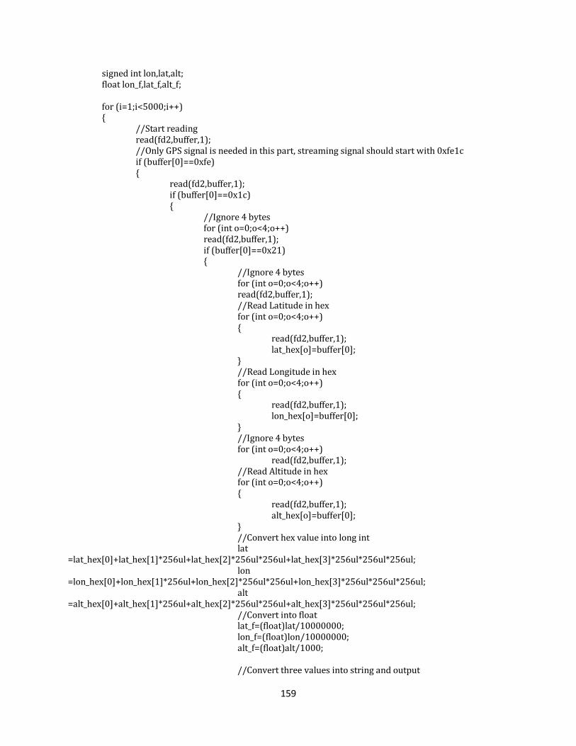
159
signed int lon,lat,alt; float lon_f,lat_f,alt_f; for (i=1;i<5000;i++) { //Start reading read(fd2,buffer,1); //Only GPS signal is needed in this part, streaming signal should start with 0xfe1c if (buffer[0]==0xfe) { read(fd2,buffer,1); if (buffer[0]==0x1c) { //Ignore 4 bytes for (int o=0;o<4;o++) read(fd2,buffer,1); if (buffer[0]==0x21) { //Ignore 4 bytes for (int o=0;o<4;o++) read(fd2,buffer,1); //Read Latitude in hex for (int o=0;o<4;o++) { read(fd2,buffer,1); lat_hex[o]=buffer[0]; } //Read Longitude in hex for (int o=0;o<4;o++) { read(fd2,buffer,1); lon_hex[o]=buffer[0]; } //Ignore 4 bytes for (int o=0;o<4;o++) read(fd2,buffer,1); //Read Altitude in hex for (int o=0;o<4;o++) { read(fd2,buffer,1); alt_hex[o]=buffer[0]; } //Convert hex value into long int lat =lat_hex[0]+lat_hex[1]*256ul+lat_hex[2]*256ul*256ul+lat_hex[3]*256ul*256ul*256ul; lon =lon_hex[0]+lon_hex[1]*256ul+lon_hex[2]*256ul*256ul+lon_hex[3]*256ul*256ul*256ul; alt =alt_hex[0]+alt_hex[1]*256ul+alt_hex[2]*256ul*256ul+alt_hex[3]*256ul*256ul*256ul; //Convert into float lat_f=(float)lat/10000000; lon_f=(float)lon/10000000; alt_f=(float)alt/1000; //Convert three values into string and output
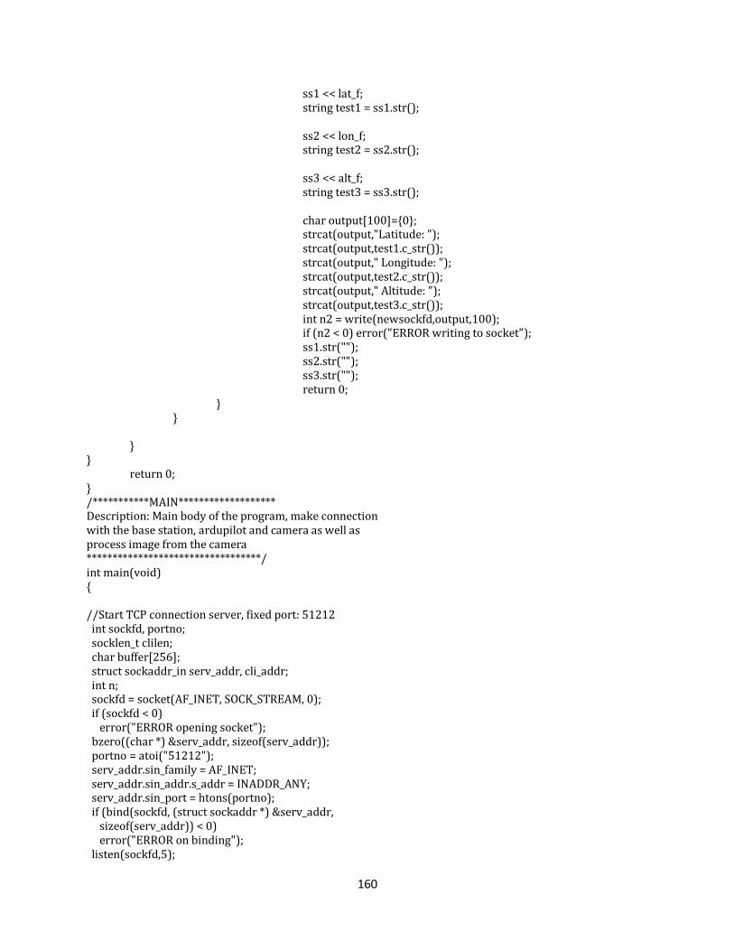
160
ss1 << lat_f; string test1 = ss1.str(); ss2 << lon_f; string test2 = ss2.str(); ss3 << alt_f; string test3 = ss3.str(); char output[100]={0}; strcat(output,"Latitude: "); strcat(output,test1.c_str()); strcat(output," Longitude: "); strcat(output,test2.c_str()); strcat(output," Altitude: "); strcat(output,test3.c_str()); int n2 = write(newsockfd,output,100); if (n2 < 0) error("ERROR writing to socket"); ss1.str(""); ss2.str(""); ss3.str(""); return 0; } } } } return 0; } /***********MAIN******************* Description: Main body of the program, make connection with the base station, ardupilot and camera as well as process image from the camera **********************************/ int main(void) { //Start TCP connection server, fixed port: 51212 int sockfd, portno; socklen_t clilen; char buffer[256]; struct sockaddr_in serv_addr, cli_addr; int n; sockfd = socket(AF_INET, SOCK_STREAM, 0); if (sockfd < 0) error("ERROR opening socket"); bzero((char *) &serv_addr, sizeof(serv_addr)); portno = atoi("51212"); serv_addr.sin_family = AF_INET; serv_addr.sin_addr.s_addr = INADDR_ANY; serv_addr.sin_port = htons(portno); if (bind(sockfd, (struct sockaddr *) &serv_addr, sizeof(serv_addr)) < 0) error("ERROR on binding"); listen(sockfd,5);
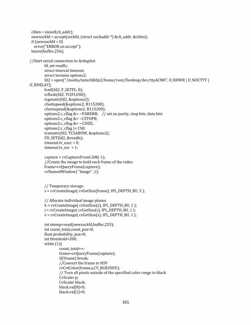
161
clilen = sizeof(cli_addr); newsockfd = accept(sockfd, (struct sockaddr *) &cli_addr, &clilen); if (newsockfd < 0) error("ERROR on accept"); bzero(buffer,256); //Start serial connection to Ardupilot fd_set readfs; struct timeval timeout; struct termios options2; fd2 = open("/media/mmcblk0p2/home/root/Desktop/dev/ttyACM0", O_RDWR | O_NOCTTY | O_NDELAY); fcntl(fd2, F_SETFL, 0); tcflush(fd2, TCIFLUSH); tcgetattr(fd2, &options2); cfsetispeed(&options2, B115200); cfsetospeed(&options2, B115200); options2.c_cflag &= ~PARENB; // set no parity, stop bits, data bits options2.c_cflag &= ~CSTOPB; options2.c_cflag &= ~CSIZE; options2.c_cflag |= CS8; tcsetattr(fd2, TCSANOW, &options2); FD_SET(fd2, &readfs); timeout.tv_usec = 0; timeout.tv_sec = 1; capture = cvCaptureFromCAM(-1); //Create the image to hold each frame of the video frame=cvQueryFrame(capture); cvNamedWindow( "Image" ,1); // Temporary storage. s = cvCreateImage( cvGetSize(frame), IPL_DEPTH_8U, 3 ); // Allocate individual image planes. h = cvCreateImage( cvGetSize(s), IPL_DEPTH_8U, 1 ); j = cvCreateImage( cvGetSize(s), IPL_DEPTH_8U, 1 ); v = cvCreateImage( cvGetSize(s), IPL_DEPTH_8U, 1 ); int ntemp=read(newsockfd,buffer,255); int count_total,count_pos=0; float probability_pos=0; int threshold=200; while (1){ count_total++; frame=cvQueryFrame(capture); if(!frame) break; //Convert the frame to HSV cvCvtColor(frame,s,CV_RGB2HSV); // Turn all pixels outside of the specified color range to black CvScalar p; CvScalar black; black.val[0]=0; black.val[1]=0;
162
black.val[2]=0; blob_area=1; total_area=s->height*s->width; buffer[0]='\0'; read(fd2,buffer,1); for(int x = 0; x < s->height - 1; x++){ for(int y = 0; y < s->width - 1; y++){ p=cvGet2D(s, x, y); if(p.val[0]>110 && p.val[0]<120 && p.val[1]>=250 && p.val[1]<260){ cvSet2D(s, x, y, p); blob_area++; } else { cvSet2D(s, x, y, black); } } } //Check blog area ratio to total area, if it is bigger than 25 start reading information from Ardupilot if ((total_area/blob_area<25)) { count_pos++; readserial(); } } //Release all allocated variables cvReleaseImage( &h ); cvReleaseImage( &j ); cvReleaseImage( &v ); cvReleaseImage( &s ); cvReleaseImage( &frame ); cvReleaseCapture( &capture ); //Close all connection close(fd2); close(newsockfd); close(sockfd); }
163
Bibliography
[1] R. Boyle, "Autonimous Search and Rescue Operations," 16 July 2010. [Online]. Available:
http://www.popsci.com/technology/article/2010-07/small-drones-could-replace-search-and-
rescue-helos-making-hiker-rescue-faster-and-cheaper.
[2] "Smithsonian National Air and Space Museum," [Online]. Available:
http://airandspace.si.edu/exhibitions/gal104/uav.cfm.
[3] B. Naylor, 5 December 2011. [Online]. Available:
http://www.npr.org/2011/12/05/143144146/drone-technology-finding-its-way-to-american-
skies.
[4] M. Lukovic, "The future of the Civil and Military UAV Market," 28 June 2011. [Online]. Available:
http://www.frost.com/sublib/display-market-insight-top.do?id=236443867.
[5] A. Service, "Drones Who Makes Them and Who Has Them," 3 march 2013. [Online].
[6] DOE, "Defense Market," 2012. [Online]. Available: http://www.defensemarket.com/?tag=uav-
market.
[7] "Microdrones," [Online]. Available: http://www.microdrones.com/products/md4-200/md4-200-
key-information.php.
[8] Kbosak, "Pteryx UAV," 27 March 2010. [Online]. Available:
http://en.wikipedia.org/wiki/File:Pteryx_UAV_-_wiki.jpg.
[9] B. Neild, "Not just for military use, Drones turn Civilian," 22 December 2012. [Online]. Available:
http://www.cnn.com/2012/07/12/world/europe/civilian-drones-farnborough.
[10] J. PAPPALARDO, 26 February 2010. [Online]. Available:
http://www.popularmechanics.com/technology/aviation/military/4347306.
[11] "Thermal Infrared Camera," 2013. [Online]. Available: http://www.draganfly.com/uav-
helicopter/draganflyer-x6/features/flir-camera.php.
[12] Draganfly Innovations Inc., "A Short History of Unmanned Aerial Vehicles (UAVs)," 2012. [Online].
Available: http://www.draganfly.com/news/2009/03/04/a-short-history-of-unmanned-aerial-
vehicles-uavs/. [Accessed 12 October 2012].
[13] T. f. Aircraft, "First cruise missile — Kettering’s Bug," 1 April 2011. [Online]. Available:
http://travelforaircraft.wordpress.com/2011/04/01/first-cruise-missile-%E2%80%94-the-
164
kettering-bug/. [Accessed 20 April 2013].
[14] "Global Security," 28 June 2011. [Online]. Available:
http://www.globalsecurity.org/intell/systems/uav-intro.htm. [Accessed 4 October 2012].
[15] The Museum of Flight, "The Fieseler Fi 103 (V1) German “Buzz Bomb”," The Museum of Flight,
2013. [Online]. Available: http://www.museumofflight.org/exhibits/fieseler-fi-103-v1. [Accessed
11 March 20131].
[16] C. Levinson, "The Wall Street Journal," Dow Jones and Company, 10 January 2010. [Online].
Available: http://online.wsj.com/article/SB126325146524725387.html. [Accessed 8 January
2013].
[17] Associataed Press, "Military.com," 2 January 2008. [Online]. Available:
http://www.military.com/NewsContent/0,13319,159220,00.html. [Accessed 4 October 2012].
[18] D. Dufrene, "The Unmanned Aerial Vehicle in Wartime," The Top Secret Writers, 2013. [Online].
Available: http://www.topsecretwriters.com/2010/11/the-unmanned-aerial-vehicle-in-wartime/.
[Accessed 11 March 2013].
[19] "U.S. Using Armed Predator Drones Over Libya," Defense Tech, 21 April 2011. [Online]. Available:
http://defensetech.org/2011/04/21/u-s-using-armed-predator-drones-over-libya/. [Accessed 21
April 2013].
[20] [Online]. Available: http://www.uavm.com/uavapplications.html.
[21] L. Bowman, September 2005. [Online]. Available:
http://www.uavm.com/images/Aerosonde_Ophelia.pdf.
[22] B. V. Bigelow, "NASA research team envisions flock of," The San Diego Union-Tribune, p. 3, 22
August 2005.
[23] A. Caumont, "Start Up," 2005.
[24] P. Tristam, "Predator Drones and other Unmanned Aerial Vehicles (UAVs)," 2012. [Online].
Available: http://middleeast.about.com/od/usmideastpolicy/a/predator-uavs-weaponry.htm.
[Accessed 2 October 2012].
[25] "Hawk AeroSpace," Hawk AeroSpace, 2012. [Online]. Available:
http://www.hawkaerospace.eu/Default.aspx?tabid=239&articleType=ArticleView&articleId=37.
[Accessed 4 October 2012].
[26] B. C. Dostal, "Enhancing Situational Understanding through the Employment of Unmanned Aerial
165
Vehicles," GlobalSecurity.org, 2013. [Online]. Available:
http://www.globalsecurity.org/military/library/report/call/call_01-18_ch6.htm. [Accessed 11
March 2013].
[27] B. Christensen, "Technovelogy," 9 September 2009. [Online]. Available:
http://www.technovelgy.com/ct/Science-Fiction-News.asp?NewsNum=2529. [Accessed 2012
October 2012].
[28] "WiFi, Bluetooth or ZigBee Wireless," Kanda, 29 May 2012. [Online]. Available:
http://www.kanda.com/blog/wireless/wifi-bluetooth-zigbee-wireless/. [Accessed 9 April 2013].
[29] C. Coleman, J. Funk, J. Salvati and C. Whipple, "Design of an Autonomous Platform for Search and
Rescue," Worcester Polytechnic Institute, Worcester, MA, 2012.
[30] M. J. Valenti, "Approximate Dynamic Programming with Applications in," Massachusetts Institute
of Technology, Cambridge, MA, 2007.
[31] T. Millet, J. Yates, B. Millar and N. Johnson, "Brigham Young University MAV Team," Brigham
Young Univerity, Provo, Utah, 2007.
[32] K. Nordberg, P. Doherty, G. Farneback, P.-E. Forssen, G. Granlund, A. Moe and J. Wiklund, "Vision
for a UAV helicoptor," Linkoping University, Linkoping, Sweden.
[33] C. Tetrault, "A Short History of Unmanned Aerial Vehicles (UAVs)".
[34] "Ponte Vecchio 17," Callai, 2013. [Online]. Available:
http://www.callaipontevecchio.com/contact_me_19.html. [Accessed 21 April 2013].
[35] J. M. SULLIVAN, "Evolution or Revolution? Rise of UAVs," IEEE Technology and Society, vol. 25, no.
3, Fall 2006.
[36] admin, "Shadow 200 tactical UAV system," 16 october 2006. [Online]. Available: http://defence-
update.com/20061016_shadown.html.
[37] R. Blackhurst, "The air force men who fly drones in Afghanistan by remote control," The
Telegraph, 24 September 2012. [Online]. Available:
http://www.telegraph.co.uk/news/uknews/defence/9552547/The-air-force-men-who-fly-drones-
in-Afghanistan-by-remote-control.html. [Accessed 11 March 2013].
[38] D. B, "Revolutionary UAV Drones," 23 January 2012. [Online]. Available:
http://strikefighterconsultinginc.com/blog/5-revolutionary-uav-drones/.
[39] "PBS," 10 October 2011. [Online]. Available: http://www.pbs.org/newshour/bb/military/july-
166
dec11/drones1_10-10.html. [Accessed 4 October 2012].
[40] J. Kopstein, "Interactive map reveals where drones are being flown inside the US right now," 6
December 2012. [Online]. Available: http://www.theverge.com/2012/12/6/3735976/interactive-
map-domestic-drones-eff.
[41] R. Waugh, "The rise of the robo-fighters: Britain's new pilotless air force," Mail Online, 5 May
2010. [Online]. Available: http://www.dailymail.co.uk/home/moslive/article-1269282/The-rise-
robo-fighters-Britains-new-pilotless-air-force.html. [Accessed 11 March 2013].
[42] A. Caumont, "Start-Up," The Washington Post, p. 1, 28 November 2005.
[43] "Division of Agriculture," University of Arkansas System, [Online]. Available:
http://www.aragriculture.org/horticulture/nursery_automation/default.htm. [Accessed March
2013].
[44] "NASA," NASA, 2003. [Online]. Available:
http://www.nasa.gov/vision/earth/everydaylife/Safer_Firefighting_prt.htm. [Accessed 2013].
[45] L. Bowman, "Drone aircraft joining hurricane-research missions," Sky Tracker, p. 2, 18 September
2005.
[46] "DWS review," 2008. [Online]. Available: http://www.digi-help.com/uavs-will-fly-into-the-eye-of-
the-hurrican-and-gather-data/. [Accessed March 2013].
[47] UAV Collaborative, "Homeland Security Project," 2012. [Online]. Available: http://www.uav-
applications.org/projects/homeland_1.html. [Accessed 3 October 2012].
[48] "Homeland Security News Wire," 2010. [Online]. Available:
http://www.homelandsecuritynewswire.com/mini-uavs-infrastructure-facilities-protection.
[Accessed March 2013].
[49] "Flat Eight Productions," Flat Eight Productions Inc., [Online]. Available:
http://www.flat8inc.com/search-and-rescue/. [Accessed March 2013].
[50] S. Srinivasan, H. Latchman, J. Shea, T. Wong and J. McNair, "Airborne Traffic Surveillance Systems -
Video Surveillance of Highway Traffic," University of Florida, Gainesville, FL.
[51] J. Elgot, "Police Drones: Unmanned Air Vehicles Could Monitor Protests, Riots And Traffic In UK,"
The Huffington Post, 2012.
[52] General Atomics Aeronautical, "MQ-1 Predator," 2012. [Online]. Available: http://www.ga-
asi.com/products/aircraft/pdf/MQ-1_Predator.pdf. [Accessed 12 October 2012].
167
[53] Arcturus UAV, "Arcturus UAV T-20," 2012. [Online]. Available: http://www.arcturus-
uav.com/docs/Arcturus-T20-SpecSheet.pdf. [Accessed 4 October 2012].
[54] M. v. Leeuwen, "New Contract at Crew Training International in Las Vegas," 2010. [Online].
Available: http://www.goiam.org/index.php/territories/western/2410-new-contract-at-crew-
training-international-in-las-vegas. [Accessed 12 October 2012].
[55] A. Brown, J. Estabrook and B. Franklin, "Sensor Processing and Path Planning Framework for s
Search and Rescue UAV Network," Worcester Polytechnic Institute, Worcester, MA, 2011.
[56] B. Bethke, "Persistent Vision-Based Search and Track Using Multiple UAVs," Massachusetts
Institute of Technology, Cambridge, MA, 2007.
[57] Texas Instruments, "OMAP Mobile Processors : OMAP™ 4 Platform," 2012. [Online]. Available:
http://www.ti.com/general/docs/wtbu/wtbuproductcontent.tsp?templateId=6123&navigationId=
12842&contentId=53247. [Accessed 2012 October 12 2012].
[58] C. Holland, "TI expands support for OMAP," 14 February 2002. [Online]. Available:
http://www.embedded.com/electronics-news/4134387/TI-expands-support-for-OMAP. [Accessed
4 October 2012].
[59] Texas Instruments, "OMAP 4 Platform : OMAP4430/OMAP4460," 2012. [Online]. Available:
http://www.ti.com/general/docs/wtbu/wtbuproductcontent.tsp?templateId=6123&navigationId=
12843&contentId=53243. [Accessed 4 October 2012].
[60] Texas Instruments, "OMAP-DM Coprocessors: OMAP-DM299/500," 2012. [Online]. Available:
http://www.ti.com.cn/general/docs/wtbu/wtbuproductcontent.tsp?templateId=6123&navigation
Id=12828&contentId=50020. [Accessed 12 October 2012].
[61] Texas Instruments, "OMAP Mobile Processors : Security," 2012. [Online]. Available:
http://www.ti.com/general/docs/wtbu/wtbugencontent.tsp?templateId=6123&navigationId=123
16&contentId=4629&DCMP=WTBU&HQS=Other+EM+m-shield. [Accessed 4 October 2012].
[62] "MSP430 16-bit ultra-low power microcontrollers (MCUs) - F6xx series," Texas Instruments, 2012.
[Online]. Available:
http://www.ti.com/paramsearch/docs/parametricsearch.tsp?familyId=2926§ionId=95&tabId
=2880&family=mcu. [Accessed 4 October 2012].
[63] Texas Instruments, "MSP430x5xx and MSP430x6xx Family User's Guide," Texas Instruments, 2012.
[64] October 2011. [Online]. Available:
http://www.xilinx.com/support/documentation/data_sheets/ds162.pdf.
168
[65] July 2012. [Online]. Available:
http://www.xilinx.com/support/documentation/user_guides/ug382.pdf.
[66] S. Asano, T. Maruyama and Y. Yamaguchi, "Performance Comparison of FPGA, GPU, and CPU in
Image Processing," IEEE, Tsukuba, 2009.
[67] S. Edwards, "Microprocessors or FPGAs?: Making the Right Choice," 2012. [Online]. Available:
http://www.rtcmagazine.com/articles/view/102015. [Accessed 12 October 2012].
[68] "The Lenna Story," 1 October 2009. [Online]. Available: http://www.cs.cmu.edu/~chuck/lennapg/.
[Accessed 12 October 2012].
[69] Paparazzi, "Autopilots," Paparazzi, 16 September 2012. [Online]. Available:
http://paparazzi.enac.fr/wiki/Autopilots. [Accessed 4 October 2012].
[70] Procerus Technologies, "Kestrel Autopilot v2.4," 2012. [Online]. Available:
http://www.procerus.com/Downloads/DataSheets/Kestrel_2.4.pdf. [Accessed 4 October 2012].
[71] Procerus Technologies, "Kestrel autopilot," Lockheed Martin Corporation, 2012. [Online].
Available: http://www.procerus.com/productsKestrelAutopilot.php. [Accessed 4 October 2012].
[72] Lockheed Martin, "Product Pricing," Lockheed Martin, 2013. [Online]. Available:
http://www.lockheedmartin.com/us/products/procerus/product-pricing.html. [Accessed 21 April
2013].
[73] Cloud Cap Technology, "Piccolo SL unmanned avionics system," 2012. [Online]. Available:
http://www.cloudcaptech.com/Sales%20and%20Marketing%20Documents/Piccolo%20SL%20Dat
a%20Sheet.pdf. [Accessed 4 October 2012].
[74] Cloud Cap Technology, "Piccolo SL," UTC Aerospace System, 2012. [Online]. Available:
http://www.cloudcaptech.com/piccolo_sl.shtm#datasheet. [Accessed 4 October 2012].
[75] OpenPilot, "OpenPilot," OpenPilot, 2012. [Online]. Available: http://www.openpilot.org/.
[Accessed 2 October 2012].
[76] OpenPilot, "OpenPilot Hardware User Manual," 2012. [Online]. Available:
http://wiki.openpilot.org/display/Doc/OpenPilot+Hardware+User+Manual. [Accessed 3 October
2012].
[77] Ubiquiti, "Bullet," Ubiquiti, 2013. [Online]. Available: http://www.ubnt.com/bullet. [Accessed 23
April 2013].
[78] "JoseMariaKim," 2013. [Online]. Available: http://josemariakim.blogspot.com/. [Accessed 23 April
169
2013].
[79] Overstock.com, "USB 2.0 Bluetooth Dongle," Overstock.com, 2013. [Online]. Available:
http://www.overstock.com/Electronics/USB-2.0-Bluetooth-Dongle/2343471/product.html.
[Accessed 23 April 2013].
[80] "FCBIX45C," Sony, 2012. [Online]. Available: http://pro.sony.com/bbsc/ssr/product-FCBIX45C/.
[Accessed 4 October 2012].
[81] Black Widow AV, "Black Widow AV Wireless Aerial Video Solutions," Black Widow AV, 2012.
[Online]. Available: http://www.blackwidowav.com/kx131.html. [Accessed 12 October 2012].
[82] [Online]. Available: http://www.draganfly.com/news/2006/11/09/draganflyer-savs-rc-helicopter-
termal-intelligence-aerial-video/.
[83] Aegis, " Sony FCB-EX780B," Aegis, 2004. [Online]. Available: http://www.aegis-
elec.com/products/sonyfcbex780b.html. [Accessed 21 April 2013].
[84] [Online]. Available: http://fisher.osu.edu/~muhanna_1/pdf/crypto.pdf.
[85] ArduPilot, "MPInstallation," DIY Drones, 9 November 2012. [Online]. Available:
http://code.google.com/p/ardupilot-mega/wiki/MPInstallation. [Accessed 10 November 2012].
[86] M. S. John, "Configure minicom to communicate with Cisco device," Youtube, 26 September 2010.
[Online]. Available: http://www.youtube.com/watch?v=vUp9TergyhQ. [Accessed 25 November
2012].
[87] G. Anescu, "Encryption/Decryption Method," 7 11 2002. [Online]. Available:
http://www.codeproject.com/Articles/1380/A-C-Implementation-of-the-Rijndael-Encryption-
Decr.
[88] A. Zaki, "Leopard Imaging Camera LI-LBCM3M1 on the Beagleboard," Embedded Geeks, 21
January 2012. [Online]. Available: http://embeddedgeeks.wordpress.com/2012/01/21/leopard-
imaging-camera-li-lbcm3m1-on-the-beagleboard/. [Accessed 26 October 2012].
[89] J. Ragsdale, "Jay Ragsdale," [Online]. Available: http://jayragsdale.com/projects/34-robotics/47-
my-first-opencv-assignment. [Accessed March 2013].
[90] P. D'Silva, "A Little About Color: HSV vs. RGB," 28 July 2008. [Online]. Available:
http://www.kirupa.com/design/little_about_color_hsv_rgb.htm. [Accessed 23 April 2013].
[91] BeamQ, "200mW Red Laser," BeamQ, 2013. [Online]. Available: http://www.beamq.com/laser-
pointers-200mw-red-laser-c-54_25.html. [Accessed 21 April 2013].
170
[92] M. Szczys, "Wifi Jamming via Deauthentication Packets," Hack a Day, 4 October 2011. [Online].
Available: http://hackaday.com/2011/10/04/wifi-jamming-via-deauthentication-packets/.
[Accessed 30 January 2013].
[93] Aircrack-ng, "Aircrack-ng," Aircrack-ng, 2013. [Online]. Available: http://www.aircrack-ng.org/.
[Accessed 5 February 2013].
[94] "Man-in-the-middle-attack," [Online]. Available: http://en.wikipedia.org/wiki/Man-in-the-
middle_attack#References.
[95] Worcester Polytechnic Institute, "Second Floor," Worcester Polytechnic Institute, 2013. [Online].
Available: http://wp.wpi.edu/reccenter/files/2012/07/sr-secondfloor.pdf. [Accessed 23 April
2013].
[96] L. Dong, Z. Han, A. Petropulu and V. H. Poor, "Improving Wireless Physical Layer Security via," IEEE
Tranasactions on Signal Processing, vol. 58, no. 3, p. 14, 2010.
[97] G. J. Gilmore, "U.S. Air Force," 23 June 2009. [Online]. Available:
http://www.af.mil/news/story.asp?id=123160247. [Accessed 4 October 2012].
[98] T. W. McLain and R. W. Beard, "Unmanned Air Vehicle Testbed for Cooperative Control
Experiments," Boston, 2004.
[99] "Wireless Handset Solutions : OMAP Mobile Processors," Texas Instruments, 2012. [Online].
Available:
http://www.ti.com/general/docs/wtbu/wtbugencontent.tsp?templateId=6123&navigationId=119
88&contentId=4638. [Accessed 4 October 2012].
[100] "Autopilot Design," Brigham Young University, 2012. [Online]. Available:
http://magicc.byu.edu/content/autopilot-design. [Accessed 3 October 2012].
[101] [Online]. Available: http://arduino.cc/en/Main/ArduinoBoardUno.
[102] "http://www.arduino.cc/," [Online].
[103] [Online]. Available: http://en.wikipedia.org/wiki/Digital_signal_processor.
[104] 28 june 2011. [Online]. Available: C:\Users\Roni\Desktop\Dropbox\MQP\UAV Markets\The
Future of the Civil and Military UAV Market.htm.
[105] [Online]. Available: http://www.marketresearchmedia.com/?p=509.
[106] [Online]. Available: http://www.uavm.com/uavapplications.html.
171
[107] B. V. Bigelow, August 2005. [Online]. Available:
http://www.uavm.com/images/Fire_Fight_NASA_research_team_envisions_flock_of_robot_aircr
aft_monitori...pdf.
[108] James Nechvatal, Elaine Barker, Lawrence Bassham, William Burr, Morris Dworkin, James Foti,
Edward Roback, "Report on the Development of Advanced Encryption Standard (AES)," 2000.
[109] April 2006. [Online]. Available:
http://ece.wpi.edu/courses/ece3803b2008/Datasheets/AT91M42800A.pdf.
[110] J. Azema and G. Fayad, "M-Shield Mobile Security Technology: making wireless secure," February
2008. [Online]. Available: http://focus.ti.com/pdfs/wtbu/ti_mshield_whitepaper.pdf. [Accessed 8
October 2012].
[111] T. Scherrer, "Video wireless for model RC planes," August 2007. [Online]. Available:
http://www.webx.dk/rc/video-wireless/video.htm. [Accessed 12 October 2012].
[112] "http://securityuncorked.com/2008/08/history-of-wireless-security/," [Online].
[113] [Online]. Available: http://searchnetworking.techtarget.com/definition/OSI.
[114] [Online]. Available:
http://www.senetas.com/products/resources/media/understanding_layer2_encryption.pdf.
[115] "Escotal," 2012. [Online]. Available: http://www.escotal.com/osilayer.html. [Accessed 14 October
2012].
[116] Y.-W. S. a. C.-C. S. Jin-Shyan Lee, "A Comparative Study of Wireless Protocols: Bluetooth, UWB,
ZigBee, and Wi-Fi," in IEEE Industrial Electronics Society, Taipei, 2007.
[117] "Mirifica," [Online]. Available: http://www.mirifica.it/store/lang-en/schede-fpga/178-digilent-
atlys-spartan-6-fpga-development-kit-academic.html. [Accessed 14 October 2012].
[118] [Online]. Available: http://www.uavm.com/images/Economics_Forcast_of_UAV_-
_Graphic_From_NASA_UAV_Capabilities_Assessment-DRAFT.pdf.
[119] Y.-W. S. a. C.-C. S. Jin-Shyan Lee, "A Comparative Study of Wireless Protocols: Bluetooth, UWB,
ZigBee, and Wi-Fi," 5-8 November 2007. [Online]. Available:
http://eee.guc.edu.eg/announcements/comparaitive_wireless_standards.pdf.
[120] U.S. Air Force, "RQ-4 GLOBAL HAWK," U.S. Air Force, 27 January 2012. [Online]. Available:
http://www.af.mil/information/factsheets/factsheet.asp?id=13225. [Accessed 11 March 2013].
172
[121] Smithsonian National Air and Space Museum, "Pioneer RQ-2A UAV," Smithsonian National Air and
Space Museum, 2013. [Online]. Available:
http://web.archive.org/web/20110429160929/http://www.nasm.si.edu/collections/artifact.cfm?i
d=A20000794000. [Accessed 11 March 2013].
[122] Arcturus UAV, "Arcturus UAV," 2013. [Online]. Available: http://www.arcturus-
uav.com/docs/products_brochure08.pdf. [Accessed 11 March 2013].
[123] Universal Printing, "More about Color: Digital Color | RGB vs. CMYK," Universal Printing, 1
September 2012. [Online]. Available: http://info.universalprinting.com/blog/bid/51844/More-
about-Color-Digital-Color-RGB-vs-CMYK. [Accessed 23 April 2013].