Secure Session Mobility for VoIP - KTH | Skolan f¶r
70
Master of Science Thesis Stockholm, Sweden 2008 COS/CCS 2008-21 SAMIR DZAFERAGIC Secure Session Mobility for VoIP KTH Information and Communication Technology
Transcript of Secure Session Mobility for VoIP - KTH | Skolan f¶r

Master of Science ThesisStockholm, Sweden 2008
COS/CCS 2008-21
S A M I R D Z A F E R A G I C
Secure Session Mobility for VoIP
K T H I n f o r m a t i o n a n d
C o m m u n i c a t i o n T e c h n o l o g y

Secure Session Mobility for VoIP
Samir Dzaferagic
Master of Science Thesis
13 October 2008
Department of Communication Systems School of Information and Communication Technology
(ICT) Royal Institute of Technology (KTH)
Stockholm, Sweden
Examiner & Supervisor at KTH: Professor Gerald Q. Maguire Jr.
Supervisor at Combitech: Christian Hamle, Consultant,
Information Security

i
Abstract High data rate wireless packet data networks have made real-time IP based services available
through mobile devices. At the same time, differences in the characteristics of radio technologies (802.11/WiFi and 3G networks) make seamless handoff across heterogeneous wireless networks difficult. Despite this, many believe that the ultimate goal of next generation networks (often referred to as the fourth generation) is to allow convergence of such dissimilar heterogeneous networks. Supporting voice over Internet Protocol in next-generation wireless systems is thought by some to require support for mobility and quality of service features. Currently a mobile node can experience interruptions or even sporadic disconnections of an on going real-time session due to handovers between both networks of different types and networks of the same type.
Many tests have already been done in this area and one may wonder why it is worth spending even more time investigating it? This thesis focuses on the important problem of providing session security despite handovers between networks (be they operated by the same operator or different operators and be they the same link technologies or different).
One of the goals in this thesis is to investigate how an ongoing speech session can continue despite a change in transmission media1. Additionally, a number of security threats that could occur due to the handover will be identified and presented. Finally, the most suitable solution to address these threats will be tested in a real environment. Eventual shortcomings and weaknesses will be identified and presented; along with suggestions for future work.
1 When utilizing IP over carriers such as wired Ethernet, WLAN, and 3G.

ii
Sammanfattning Trådlösa hög-hastighets datanät har möjliggjort appliceringen av realtids tjänster på mobil
utrustning över IP. Samtidigt har skillnaderna i de olika radioteknologierna (802.11/WiFi och 3G näten) introducerat nya problem med att upprätthålla trådlösa kommunikationen tvärs den heterogena trådlösa accessen. Många tror att slutmålet för nästa generations nätverk (ofta refererade som fjärde generationens nätverk) är att tillåta konvergensen av dessa olika heterogena nätverk. Stödet för Voice over Internet Protokollet (VoIP) i nästa generations trådlösa nät tror somliga kräver ett inslag av kombination mellan mobilitet samt upprätthållandet av kvaliteten. För närvarande kan den mobila noden (MN) råka ut för störningar och även sporadiska avbrott av en pågående realtidssessionen på grund av övergångar mellan samma eller olika typer av medier.
Många tester har redan gjorts inom det här området och man kan fråga sig varför det är värt att lägga ner ännu mer tid på att undersöka det här? Det här examensarbetet fokuserar på det viktiga problemet som handlar om att kunna erbjuda sessions säkerhet trots övergångar mellan näten (oavsett om dessa drivs av samma eller olika operatörer samt oavsett om de är av samma eller olika nätverks typ).
Ett av målen för det här examensarbetet är att undersöka hur en pågående talsession behålls vid byte av transmissionsmedia2. Vidare kommer olika säkerhetsaspekter och hot som kan tänkas uppstå vid bytet att identifieras och presenteras. Slutligen kommer den mest lämpade lösningen till problemet att testas i verklig miljö. Eventuella brister och svagheter kommer att identifieras och redovisas i slutet av rapporten tillsammans med förslag på framtida arbete.
2 Då man nyttjar IP bärare som trådbundet Ethernet, WLAN och 3G.
iii
Acknowledgements I would like to show gratitude to my friend Admir Muhovic who contributed in establishing
my contact with Combitech AB.
All the people at IS department at Combitech AB in Växjö deserve to be mentioned, they made me feel like one of them from the first day I arrived. Especially Christian Hamle, my supervisor at the Combitech who provided me with important information about my thesis topic and all other practical details at the company. I thank Lena Johansson for administrative help and that she, together with others, gave me opportunity to do my master thesis at the IS department.
My greatest gratitude goes to Professor Gerald Q. Maguire Jr. who really is an expert in the area of communication systems and without whom this master thesis would not be the same. I thank him for the time he spent providing me with vital information about this thesis topic.
All members of my family deserve special thanks since they always gave me unconditional support and strength to finish this thesis.
Finally, I would like to thank Djana, who became my wife during this thesis work and my friends who supported me during good and bad moments.

iv
Contents Abstract ............................................................................................................................................ i Sammanfattning .............................................................................................................................. ii Acknowledgements........................................................................................................................ iii Contents ......................................................................................................................................... iv List of Figures ................................................................................................................................ vi List of Tables ................................................................................................................................ vii Abbreviations and Acronyms ...................................................................................................... viii 1 Introduction.................................................................................................................................. 1
1.1 General overview.................................................................................................................. 1 1.2 A scenario: Walking out of office......................................................................................... 1 1.3 Problem statement................................................................................................................. 2 1.4 Goals of this Masters Thesis ................................................................................................. 3
2 Background.................................................................................................................................. 4 2.1 VoIP ................................................................................................................................ 4 2.2 VoIP protocol stack......................................................................................................... 6
2.2.1 SIP Signaling .......................................................................................................... 6 2.2.2 Session description.................................................................................................. 8 2.2.3 Key exchange: SDES, ZRTP, and MIKEY ............................................................ 9 2.2.4 RTP and SRTP...................................................................................................... 11 2.2.5 SIP Network.......................................................................................................... 12
2.3 Mobility......................................................................................................................... 12 2.3.1 Definition of mobility ........................................................................................... 12 2.3.2 Heterogeneous networks & Handoffs................................................................... 13 2.3.3 Networks ............................................................................................................... 13
2.4 VoIP clients: Skype, MiniSip, and Fring ...................................................................... 14 3 Related work .............................................................................................................................. 15
3.1 Corporate Wireless IP Telephony................................................................................. 15 3.2 Security for IP Multimedia Applications over Heterogeneous Networks .................... 15 3.3 Adaptive Wireless Multimedia Services....................................................................... 16 3.4 IP telephony: mobility and security .............................................................................. 16 3.5 Secure Internet Telephony: Design, Implementation, and Performance Measurement 17 3.6 Mobility for IP: Performance, Signaling, and Handoff Optimization (mipshop) working group........................................................................................................................... 18
4 VoIP network attacks................................................................................................................. 19 4.1 Denial of Service in a VoIP Network ........................................................................... 19
4.1.1 UDP flooding attacks............................................................................................ 20 4.1.2 TCP SYN flood attacks......................................................................................... 20 4.1.3 Operating System flaws or application weaknesses ............................................. 20 4.1.4 ICMP and Smurf Flooding Attacks ...................................................................... 20 4.1.5 Wireless DoS attack.............................................................................................. 21 4.1.6 Countermeasures for flooding attacks against VoIP Network Infrastructure....... 22
4.2 VoIP Network Eavesdropping ...................................................................................... 23 4.2.1 TFTP Configuration File Sniffing ........................................................................ 23 4.2.2 Number Harvesting and Call Pattern Tracking..................................................... 23 4.2.3 Call Eavesdropping............................................................................................... 24 4.2.4 TFTP Sniffing Countermeasures .......................................................................... 24

v
4.2.5 Number Harvesting and Call Pattern Tracking Countermeasures........................ 24 4.2.6 Call Eavesdropping Countermeasures .................................................................. 24 4.2.7 Virtual Private Networks: IPsec and TLS............................................................. 25
4.3 VoIP Network Interception (Man-in-the-Middle) ........................................................ 26 4.3.1 ARP altering.......................................................................................................... 26 4.3.2 Network Man-in-the-Middle Countermeasures.................................................... 27
5 VoIP Session attacks.................................................................................................................. 28 5.1 Signalling Manipulation................................................................................................ 28 5.2 Signalling Manipulation Countermeasures................................................................... 28 5.3 Media Manipulation...................................................................................................... 29 5.4 Media Manipulation countermeasures.......................................................................... 29 5.5 Signalling and Media Manipulation Summary ............................................................. 30
6 Link change................................................................................................................................ 31 6.1 Mobile IPv4 .................................................................................................................. 31 6.2 Mobile IPv6 .................................................................................................................. 32 6.3 SIP Mobility.................................................................................................................. 34 6.4 Handover procedure...................................................................................................... 35
6.4.1 Before handover.................................................................................................... 36 6.4.2 Upcoming handover.............................................................................................. 36 6.4.3 Handover process.................................................................................................. 37
6.5 Link change: summary.................................................................................................. 39 7 Practical test ............................................................................................................................... 40 8 Test analysis............................................................................................................................... 42
8.1 Test observations .......................................................................................................... 42 8.1.1 Enabling IPv6 and OpenSIPS ............................................................................... 42 8.1.2 Enabling MIPv6 .................................................................................................... 43 8.1.3 Homeguy 1.0......................................................................................................... 44
8.2 Reorganisation .............................................................................................................. 46 8.3 Alternative solution....................................................................................................... 46
8.3.1 Delays due to change of IP address in SIP mobility............................................. 47 8.3.2 A secure re-INVITE message ............................................................................... 48 8.3.3 Securing the real-time media ................................................................................ 48 8.3.4 Measurements of handover delays for SIP mobility in IPv6 ................................ 49 8.3.5 Security aspect ...................................................................................................... 51 8.3.6 Secure SIP UA with SIP mobility support............................................................ 51
9 Conclusion ................................................................................................................................. 52 10 Future work.............................................................................................................................. 54 References..................................................................................................................................... 55 Appendix A: Configuration for testing with Homeguy 1.0 .......................................................... 58

vi
List of Figures
Figure 1. Coding/Decoding of voice............................................................................................... 4 Figure 2. Voice over IP protocol stack ........................................................................................... 6 Figure 3. SIP protocol exchange.................................................................................................... 7 Figure 4. Diffie-Hellman method ................................................................................................. 11 Figure 5. Example of a SIP based VoIP network architecture ..................................................... 12 Figure 6. DDoS attack example .................................................................................................... 19 Figure 7. TCP three-way handshake............................................................................................. 20 Figure 8. Wireless DoS................................................................................................................. 21 Figure 9. Layered security for a WLAN....................................................................................... 23 Figure 10. SIP security mechanisms on different layers............................................................... 24 Figure 11. Man-in-the-Middle concept........................................................................................ 26 Figure 12. Alice moves from WLAN 1 to WLAN 2 .................................................................... 31 Figure 13. Binding Update message exchange during Alice’s handover in MIPv6..................... 34 Figure 14. MIPv6 Handover Procedure ........................................................................................ 36 Figure 15. When to make a successful handover.......................................................................... 37 Figure 16. SIP & Mobile IPv6 test network ................................................................................. 42 Figure 17. SIP re-INVITE............................................................................................................ 47 Figure 18. Handoff flow ............................................................................................................... 49 Figure 19. SIP mobility testbed setup ........................................................................................... 50
vii
List of Tables Table I. Some differences between MIPv4 and MIPv6........................................................... 30 Table II. Handoff delay of signalling………………………………………………………….53 Table III. Handoff delay of media UDP packet………………………………………………53 Table IV. UA’s with encryption and SIP mobility support………………………………….54

viii
Abbreviations and Acronyms AP Access Point AR Access Router ARP Address Resolution Protocol BA Binding Acknowledgment BU Binding Update CAR Current Access Router CARD Candidate Access Router Discovery CEF Cisco Express Forwarding COA Care-of IP Address CODEC Coder/Decoder CoT Care-of Test CoTI Care-of Test Initiation DAD Duplicate Address Detection DDoS Distributed Denial of Service DHCP Dynamic Host Configuration Protocol DNS Domain Name System DTLS Datagram Transport Layer Security ESP Encapsulating Security Payload GPRS General Packet Radio Service GSM General System for Mobile Communications HA Home Agent HoT Home Test HoTI Home Test Initiation HTTP Hyper Text Transfer Protocol ICMP Internet Control Message Protocol ICQ “I seek you” Instant Messaging (a computer Program) IETF Internet Engineering Task Force IP Internet Protocol IPsec IP Security ISP Internet Service Provider ITU-T International Telecommunication Union-Telecommunication Standardization
Sector LAN Local Area Network MAC Media Access Control MAP Mobility Anchor Point MIKEY Multimedia Internet KEYing MIP Mobile IP MIPv4 Mobile IPv4 MIPv6 Mobile IPv6 MSN Microsoft Network Instant Messaging (a computer Program) MTU Maximum Transmission Unit NAR New Access Router NAT Network Address Translation OS Operating System PBX Private Branch Exchange PDA Personal Digital Assistant PKI Public Key Infrastructure

ix
PSTN Public Switched Telephone Network QoS Quality of Service RF Radio Frequency RR Return Routability RTP Real-time Transport Protocol SBC Session Border Controller SCTP Stream Control Transmission Protocol SPIT Spam over Internet Telephony SRTP Secure Real-time Transport Protocol SSL Secure Sockets Layer STUN Simple Traversal of UDP over NAT S/MIME Secure/Multipurpose Internet Mail Extensions TCP Transport Control Protocol TFTP Trivial File Transfer Protocol TLS Transport Later Security UA User Agent UDP User Datagram Protocol UMTS Universal Mobile Telecommunication System URI Uniform Resource Identifier USB Universal Serial Bus VoIP Voice over IP VPN Virtual Private Network VLAN Virtual Local Area Network WPA WiFi Protected Access WCDMA Wideband Code Division Multiple Access WiFi Wireless Fidelity WLAN Wireless Local Area Network ZRTP Zimmermann Real-time Transport Protocol
1
1 Introduction
1.1 General overview Since the end of the 1990s, the use of mobile devices (particularly cellular phones and
laptops) has increased dramatically thanks to the increased integration of computing and wireless communications. Many people need to be mobile and reachable at all times independent of where they are. Of these, some need to have access to email, voice mail, banking services, web browsing, and so on.
Today, this expectation has evolved so that people want to have the same IP-services as are available on their stationary computers (at home or at work). Another trend is that young people and large organizations prefer to own laptops rather than stationary machines. This choice is due to the mobility and flexibility which laptop computers offer. Users can take their work with them wherever they go. This mobility is especially appreciated by employees and employers in multinational companies as they have offices in many different countries. It is convenient that employees can bring their computer with them as they travel both to different sites of the company, but also so that the employee can work in the field (often at their customer’s site).
Laptops are usually equipped both with a wired Ethernet interface and a wireless interface allowing the user to easily connect to different access networks. The wireless local area network (WLAN) allows the computer to access IP based services from public hotspots or other locations which provides WLAN access. As nearly all laptops are equipped with analog audio input and output or USB interfaces into which a USB headset can be plugged, software to provide voice over IP (VoIP) enables the user to call to others, including friends, coworkers, customers, etc. Gateways operated by numerous VoIP service providers make it possible to call a subscriber who has only a regular Public Switched Telephone Network (PSTN) telephone, thus making VoIP service useful for nearly all calls.
Due to the development of mobile devices (such as cellular phones and handheld computers), it is now possible to make VoIP calls from your mobile phone or personal digital assistant (PDA). PDAs have gone from simply keeping calendars, schedules, and address book information to become a phone, computer, media player, etc. Today, a PDA can access high speed data wireless networks in several ways, typically WLAN access or via a 3G cellular network. The result is that increasingly the user has one device for making calls and for a wide variety of other purposes, such as access to Internet communities. This device is increasingly able to take advantage of both wide-area cellular and home/hotspot wireless coverage.
The use of a public shared communication infrastructure such as the Internet has one major drawback: security. Security is always a key concern and a basic requirement from companies who handle information which they must handle according to local and international data privacy regulations. In addition, some of this data must also be protected under even more stringent regulations when it concerns medical patients, financial transactions, national security, etc.
In the case of wireless network connectivity, another key requirement is session mobility. By session mobility we mean that a user should be able to maintain an ongoing session, be it a VoIP session or other type of session (such as video call session), despite changing transmission media or network provider.
1.2 A scenario: Walking out of office An employee, we will call him Martin, is sitting in his office reading emails on his laptop.
On the table, beside him, lies his PDA which along with the laptop is connected to the

2
company’s WLAN. An incoming VoIP call is announced and Martin interrupts his reading to accept the call. The PDA’s screen displays the name and phone number of a friend whom he is supposed to meet in a nearby café very soon. Using his headset Martin answers the call via his PDA. The friend tells him that he can not find the café and asks Martin to guide him through the streets. While Martin is speaking to his friend, he leaves the office and goes out on to the street heading for the café. At some point he reaches the limits of his company’s WLAN coverage and the PDA automatically establishes connectivity via Martin’s subscription to a 3G network. Shortly after this Martin arrives at the café. This particular café offers all its customers free WLAN access. Because Martin has been here before his PDA recognizes this particular WLAN and simply hands over the on going call to this WLAN network connection. It does this because it is programmed to use WLAN whenever it is available, rather than 3G; as the assumption is that WLAN access is both less expensive and offers greater bandwidth. After several minutes Martin’s friend arrives and Martin terminates the call. Now the two of them discuss their new business ideas face-to-face over a delicious cup of coffee.
1.3 Problem statement A detailed investigation into the scenario above reveals some possible security weaknesses
and possible issues in voice quality which must be investigated and solved. These weaknesses also reveal why we are interested in secure session mobility for VoIP, which will be the focus of this thesis. This thesis will build upon prior work that has been done in this area (details of this are presented in chapter 3).
Some of the problems are:
• How can two users be sure that no one can eavesdrop on their conversation? • Can a user be sure that his call, while he is moving, will not be disconnected due to his
motion or due to handoff between different cells of the same or different network technologies?
• What security risks does handoff imply? • How can service disruption during a handoff procedure be minimized? • If the network link quality decreases, can a user expect that the quality of voice will be
sufficient to maintain the conversation? Although, some failures happen even for purely cellular voice systems; the goal is a comparable level of quality – even for a heterogeneous system.
We will begin by investigating how a VoIP call can be made from a device which has both WLAN and 3G interfaces; this analysis can easily be extended to other transmission media. During this investigation we will examine what technologies, services, and policies are applicable. After laying this foundation, we will examine in detail what happens when the transmission media is changed during an ongoing VoIP session and how the session can be maintained in a secure way. Thus a low level policy of switching from 3G to lover cost WLAN access should not reduce the security of the on-going call.
We should note that even if the media does not change, there is a risk that the call can be disconnected. This can occur because the user is moving and enters an area where there is no network coverage (this is true even for cellular phones in 3G networks). Furthermore, the probability of interception is nearly 100 % for nearly all wireless networks (except for some special military and espionage links). We will identify existing threats, then determine which standards and techniques best support session mobility.

3
In the end, we will implement the most suitable practical solution to avoid or minimize these threats and test it in a real environment. If any shortcomings and flaws are found during testing they will be identified and presented in the report.
1.4 Goals of this Masters Thesis Main questions:
• How shall an ongoing speech session be maintained while the transmission media is changed? (The transmission media which we will consider are Ethernet, WLAN, and 3G.)
• How is this done in a secure way? • Does the proposed solution function in a real environment?
Sub questions:
• Which threats exist today against session mobility? • How extensive are they? • Which standards exist already and which standards are being developed to support session
mobility? • Which standard/standards do the major telecommunication vendors (Ericsson, Cisco, and
Nokia) prefer? – Market research. • Which standard/standards best reduce the security threat level?
A practical test of the proposed solution should be made in order to show that this solution is suitable for addressing existing threats (detailed in the answer to the question above). If any faults and shortcomings are found in the solution during testing they will be identified and presented in this thesis.

4
2 Background
2.1 VoIP Voice over IP (VoIP) is a service which enables the transmission of real-time voice/video
and related signaling over IP [1]. Often when some one who is unfamiliar with the technology says VoIP, he/she refers to the actual transmission of voice rather than the protocol implementing it. VoIP also has many other names, such as: Broadband telephony, Internet telephony, IP telephony, and Broadband Phone.
A VoIP implementation (for speech) transmits analog audio encoded as digital packets. We can see a simple example of this in Figure 1. The speech, which is an analog signal from a microphone is converted using a Coder/Decoder (CODEC) to a digital form and is encapsulated using a transport protocol and transmitted as IP packets. The selection of CODEC is a balance between voice quality, the available processing power, and bandwidth requirements [2]. It should also be noted that the choice of CODEC can also depend upon the expected impairments of the communication channel, the desired maximum delay, whether the voice is part of duplex or simplex communication, etc. The stream of the encapsulated voice packets is sent using IP to a receiver which uses the corresponding CODEC to convert the signal from digital format back to an analog signal. The analog signal then propagates to the receiver’s ear. A similar process can be used for transmitting video, still images, text, etc.
Internet
Speech colletion PlaybackCoding DecodingTransfer
Figure 1. Coding/Decoding of voice
VoIP offers some advantages in comparison to the regular telephony over PSTN. In particular:
• It can be less expensive. • For example, with a typical subscription to an internet service provider (ISP), PC-to-PC
calls do not incur additional charges; since from the point of view of the internet the voice packets are simply packets – the transmission of which is already paid for in the user’s monthly subscription.
• In case of a PC-to-Phone call a long distance “call” costs almost nothing in comparison to regular tariffs (i.e., if the call had been made in the traditional way); as using VoIP the call can transit the internet until it reaches a gateway to the PSTN near to where the callee is located, in many cases this means that the call can be delivered as a local call and not as an international circuit switch call. It is interesting to note that because of the advantages of multiplexing packets on high speed networks, international circuit switched calls are often actually VoIP calls, even if the user might not know this.
• VoIP is more versatile and open to new implementations. Integration of VoIP and data implementations may offer new features. One example would be a button on a bank’s webpage which a user may click to directly speak to one of the bank’s customer service agents in order to get help with his or her bank business or transaction [1]. This service is sometimes called “click-to-call”.
5
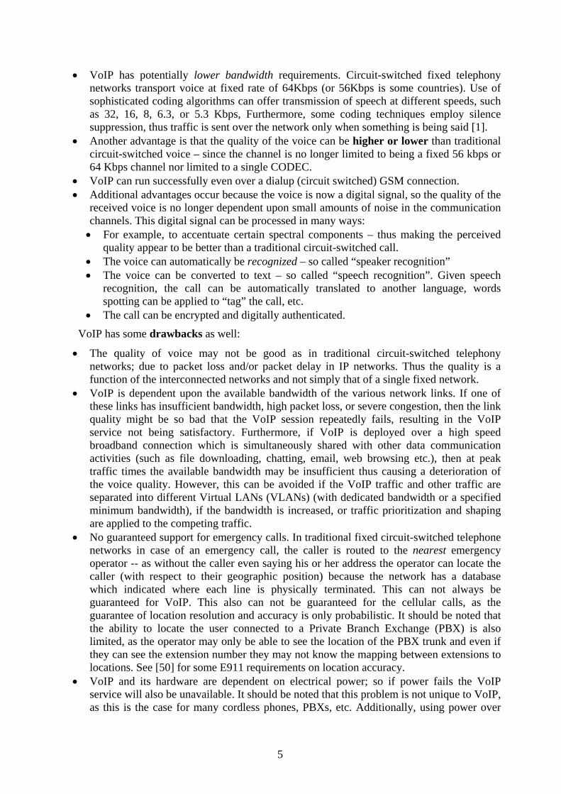
• VoIP has potentially lower bandwidth requirements. Circuit-switched fixed telephony networks transport voice at fixed rate of 64Kbps (or 56Kbps is some countries). Use of sophisticated coding algorithms can offer transmission of speech at different speeds, such as 32, 16, 8, 6.3, or 5.3 Kbps, Furthermore, some coding techniques employ silence suppression, thus traffic is sent over the network only when something is being said [1].
• Another advantage is that the quality of the voice can be higher or lower than traditional circuit-switched voice – since the channel is no longer limited to being a fixed 56 kbps or 64 Kbps channel nor limited to a single CODEC.
• VoIP can run successfully even over a dialup (circuit switched) GSM connection. • Additional advantages occur because the voice is now a digital signal, so the quality of the
received voice is no longer dependent upon small amounts of noise in the communication channels. This digital signal can be processed in many ways: • For example, to accentuate certain spectral components – thus making the perceived
quality appear to be better than a traditional circuit-switched call. • The voice can automatically be recognized – so called “speaker recognition” • The voice can be converted to text – so called “speech recognition”. Given speech
recognition, the call can be automatically translated to another language, words spotting can be applied to “tag” the call, etc.
• The call can be encrypted and digitally authenticated.
VoIP has some drawbacks as well:
• The quality of voice may not be good as in traditional circuit-switched telephony networks; due to packet loss and/or packet delay in IP networks. Thus the quality is a function of the interconnected networks and not simply that of a single fixed network.
• VoIP is dependent upon the available bandwidth of the various network links. If one of these links has insufficient bandwidth, high packet loss, or severe congestion, then the link quality might be so bad that the VoIP session repeatedly fails, resulting in the VoIP service not being satisfactory. Furthermore, if VoIP is deployed over a high speed broadband connection which is simultaneously shared with other data communication activities (such as file downloading, chatting, email, web browsing etc.), then at peak traffic times the available bandwidth may be insufficient thus causing a deterioration of the voice quality. However, this can be avoided if the VoIP traffic and other traffic are separated into different Virtual LANs (VLANs) (with dedicated bandwidth or a specified minimum bandwidth), if the bandwidth is increased, or traffic prioritization and shaping are applied to the competing traffic.
• No guaranteed support for emergency calls. In traditional fixed circuit-switched telephone networks in case of an emergency call, the caller is routed to the nearest emergency operator -- as without the caller even saying his or her address the operator can locate the caller (with respect to their geographic position) because the network has a database which indicated where each line is physically terminated. This can not always be guaranteed for VoIP. This also can not be guaranteed for the cellular calls, as the guarantee of location resolution and accuracy is only probabilistic. It should be noted that the ability to locate the user connected to a Private Branch Exchange (PBX) is also limited, as the operator may only be able to see the location of the PBX trunk and even if they can see the extension number they may not know the mapping between extensions to locations. See [50] for some E911 requirements on location accuracy.
• VoIP and its hardware are dependent on electrical power; so if power fails the VoIP service will also be unavailable. It should be noted that this problem is not unique to VoIP, as this is the case for many cordless phones, PBXs, etc. Additionally, using power over

6
Ethernet connections fixed LAN attached VoIP terminals can be powered – in some settings these devices are powered using a power supply system with emergency backup. In the case of access via wide area cellular systems, unless the base station controllers, etc. have redundant backup power – these too will not work (the aftermath of the storm Gudrun is good example).
• Security is another weakness for VoIP. Many VoIP user agents have not focused on security -- since their priority was often functionality -- although there exist good solutions which offer rather high security (such as Skype’s proprietary security mechanisms [23] and MIKEY + SRTP in MiniSip [24]).
2.2 VoIP protocol stack A VoIP protocol stack is presented in Figure 2. This is not the only possible VoIP protocol
stack (as there are others, such as Skype’s proprietary solution and ITU-T’s H.323). However, the Session Initiation Protocol (SIP) + Real-time protocol (RTP) stack is widely used and many open source implementations exist. We will consider the protocols needed for establishment and maintenance of a voice session along with the protocols used to transfer the actual voice (or other) content. As shown in the figure, these protocols can be divided into two different stacks: signaling and media transport, which together make up the VoIP stack.
TCP UDP
SDES, MIKEY
SDP
SIP
ZRTPRTPSRTP
Signaling Media transport
IPv4, IPv6
Net
wor
kTr
ansp
ort
Figure 2. Voice over IP protocol stack [31]
With regard to Figure 2, it should be noted that the signaling could also use UDP, TLS over TCP, SCTP, TLS over SCTP, etc. – rather than TCP. The ability to use TLS is frequently used to secure the signaling traffic. (This will be examined later in section 5.1.)
2.2.1 SIP Signaling The Session Initiation Protocol (SIP) [3] is an IETF standard. It is an application layer
signaling protocol to establish, modify, and terminate sessions with one or more participants. A SIP network is based on User Agents (UA), proxies, location servers, and registrars. UAs are also called end points. An UA executes on a computer with network connectivity. SIP users are not bound to one specific device; they simply register the address of their UA or UAs with their registrars. To identify a user a special type of Uniform Resource Identifier (URI) called a SIP URI is used [4]. Unlike the case of e-mail, where the e-mail message is simply delivered to the e-mail server for potentially later delivery to (or fetching by) the user; in the case of SIP the caller often wants to establish an interactive communication session with the user, therefore locating the target (callee’s) user agent(s) is necessary. However, for both scaling reasons and for privacy reasons the caller does not need to know the current location(s) of the callee’s agent(s) in

7
advance, thus the callee’s proxy uses the information from the callee’s user agent’s registration with the registrar to locate the callee’s user agent(s) [3]. It is up to callee’s proxy and their user agents to decide if the callee wants to accept this call and only then is the network address of the callee’s UA known by the caller. (Note that this address might be a mobile IP address and not the actual current address of the UA’s point of network attachment – see [27].)
SIP uses a three-way handshake to communicate the interest by the caller to establish a session with the callee and for the callee to indicate that it is interested in participating in the proposed session. In addition, this handshaking also exchanges the parameters for the actual session which will take place directly between caller and the callee(s). In Figure 3 we can see the messages exchanged when SIP (via intermediate proxies) is used to establish a session between two user agents [3].
Before a session between Alice’s and Bob’s UAs can be set up, Bob’s SIP URI must be resolved into the IP address of the UA which Bob has previously registered. SIP address resolution and routing is done by the proxy server for Bob’s SIP domain [4]. Thus the first step which Alice’s UA must make is to learn the address of the proxy for Bob’s SIP domain.
Alice’s proxy will perform a DNS lookup for the domain specified in Bob’s SIP URI to find out the address of Bob’s proxy server. This domain is identified by extracting the domain name part of the SIP URI or based upon the explicit IP address if this is included in the SIP URI. Here we will assume that a service record indicating a SIP server for this domain is returned as the result of this DNS query. (Details of this lookup are described in [56]). After learning the address of Bob’s proxy a Session Description Protocol (SDP) in the body of the SIP (INVITE and OK) messages is used to pass the session details between the UAs. SDP is described in section 2.2.2.
A lice B obatlan ta .com proxy
b iloxi.com proxy
IN V ITE
100 Trying
100 Try ing
180 R ing ing
IN V ITE
IN V ITE
180 R ing ing
180 R ing ing 200 O K
200 O K
200 O K
AC K
M edia Sess ion
B YE
200 O K
Figure 3. SIP protocol exchange [3]
As shown in Figure 3, in order to establish a call to Bob, Alice’s UA sends a SIP INVITE request either to Bob’s proxy server or to an intermediate proxy server(s) (for example, Alice’s

8
SIP domain might offer an out-going proxy server so that Alice’s UA does not have to locate Bob’s proxy server by it self). The INVITE message contains Session Description Protocol (SDP) information (i.e., type of media, supported CODEC(s), port numbers, and media protocol), which is forwarded to Bob’s UA via his proxy server based on Bob’s UA’s earlier SIP registration.
When the INVITE message reaches an intermediate server, this server sends back a 100 Trying message to the caller. This message indicates that the INVITE message has been received correctly and that the intermediate proxy is processing this request. Because Alice’s UA receives this message it knows that it does not need to retransmit the INVITE request (as it has been successfully received by the proxy who will now take responsibility for processing this request).
When Bob’s UA starts ringing it sends a 180 Ringing message via SIP so that Alice’s UA knows that the Bob’s UA is ringing.
Since Bob wants to talk to Alice, he accepts the call by ‘answering the phone’3. This generates a 200 OK message which is sent back to Alice through the SIP network. The OK message also contains an SDP part that confirms the media session’s parameters offered by Alice (to which Bob’s UA is interested) and contains the session parameters offered by Bob’s UA.
After receiving the OK message, Alice responds with an ACK which confirms to Bob the reception of the OK message and her agreement to Bob’s session parameters. With this OK message the three-way handshake (i.e., INVITE, OK, and ACK) is completed. The cases where Bob or Alice does not want to accept the session parameters or does not even wishes to participate in the call have not been described here, but can be found in [26].
The exchange of media during the session generally takes place directly between Alice’s and Bob’s respective UAs (note however, that the session need not to take place between these two UAs, but does take place between the devices whose IP addresses and port numbers were agreed to in the SDP messages). (For an example of using different devices for the actual session than used to set up the session see [51].)
SIP messages can be sent over UDP only if the packets do not exceed the MTU size; otherwise they can be sent via TCP [4]. It should be noted that other transport protocols (such as SCTP, TLS, … ) can be used.
2.2.2 Session description The Session Description Protocol (SDP) [5] is a format for describing the streaming media
parameters for a session announcement, session invitation, and so on. Since SDP is purely a format for this specification it is independent of the transport layer, so it may be carried by a number of protocols [5]. In the context of this thesis, we are only concerned when SDP is carried by SIP.
The use of SDP in SIP is based upon an Offer/Answer [6] model. In this model, one of the users makes an offer (formatted as an SDP message) – which specifies the set of media streams and CODECs that the offerer can use, together with the IP addresses and ports it would like to use to receive the associated media. The offer is passed to the other party (called the answerer). The answerer forms an answer, formatted as a SDP message that responds to the offer sent by the offerer. The answer indicates for each media stream in the offer, whether the stream is acceptable or not. Included in the answer is a proposal for media sessions (containing IP addresses and
3 How Bob ‘answers’ is outside the scope of this thesis. Bob could perform this operation by pushing a button on one of his devices (for example, a button on a handset or headset), via a speech command to one of his devices, by picking up the device (as detected by an accelerometer), etc.
9
ports, media types, CODEC(s), etc.) that the answerer wants to use in order to receive the media. An example of an offer/answer exchange can be found in [6]. SDP can also be used to carry information used in conjunction with a key exchange. This is discussed in the next section.
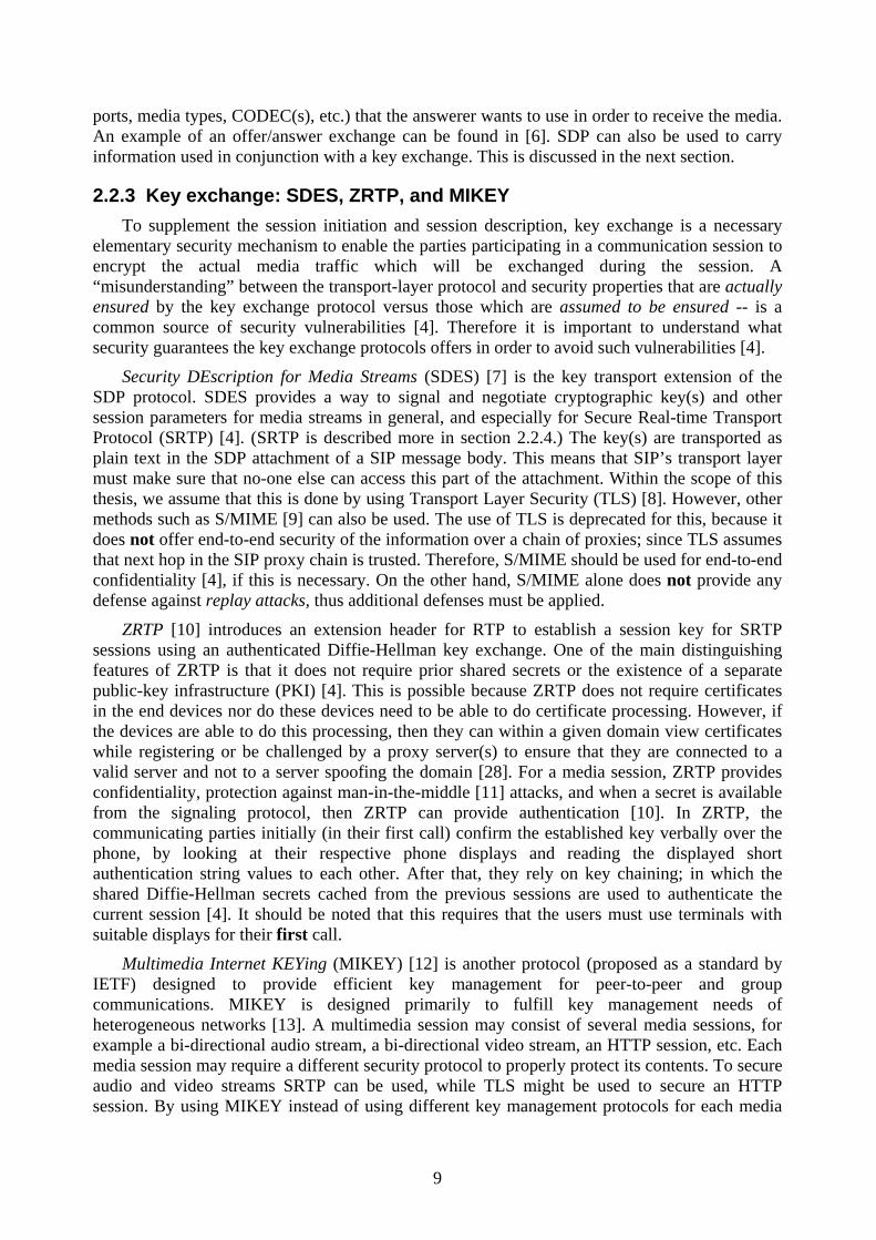
2.2.3 Key exchange: SDES, ZRTP, and MIKEY To supplement the session initiation and session description, key exchange is a necessary
elementary security mechanism to enable the parties participating in a communication session to encrypt the actual media traffic which will be exchanged during the session. A “misunderstanding” between the transport-layer protocol and security properties that are actually ensured by the key exchange protocol versus those which are assumed to be ensured -- is a common source of security vulnerabilities [4]. Therefore it is important to understand what security guarantees the key exchange protocols offers in order to avoid such vulnerabilities [4].
Security DEscription for Media Streams (SDES) [7] is the key transport extension of the SDP protocol. SDES provides a way to signal and negotiate cryptographic key(s) and other session parameters for media streams in general, and especially for Secure Real-time Transport Protocol (SRTP) [4]. (SRTP is described more in section 2.2.4.) The key(s) are transported as plain text in the SDP attachment of a SIP message body. This means that SIP’s transport layer must make sure that no-one else can access this part of the attachment. Within the scope of this thesis, we assume that this is done by using Transport Layer Security (TLS) [8]. However, other methods such as S/MIME [9] can also be used. The use of TLS is deprecated for this, because it does not offer end-to-end security of the information over a chain of proxies; since TLS assumes that next hop in the SIP proxy chain is trusted. Therefore, S/MIME should be used for end-to-end confidentiality [4], if this is necessary. On the other hand, S/MIME alone does not provide any defense against replay attacks, thus additional defenses must be applied.
ZRTP [10] introduces an extension header for RTP to establish a session key for SRTP sessions using an authenticated Diffie-Hellman key exchange. One of the main distinguishing features of ZRTP is that it does not require prior shared secrets or the existence of a separate public-key infrastructure (PKI) [4]. This is possible because ZRTP does not require certificates in the end devices nor do these devices need to be able to do certificate processing. However, if the devices are able to do this processing, then they can within a given domain view certificates while registering or be challenged by a proxy server(s) to ensure that they are connected to a valid server and not to a server spoofing the domain [28]. For a media session, ZRTP provides confidentiality, protection against man-in-the-middle [11] attacks, and when a secret is available from the signaling protocol, then ZRTP can provide authentication [10]. In ZRTP, the communicating parties initially (in their first call) confirm the established key verbally over the phone, by looking at their respective phone displays and reading the displayed short authentication string values to each other. After that, they rely on key chaining; in which the shared Diffie-Hellman secrets cached from the previous sessions are used to authenticate the current session [4]. It should be noted that this requires that the users must use terminals with suitable displays for their first call.
Multimedia Internet KEYing (MIKEY) [12] is another protocol (proposed as a standard by IETF) designed to provide efficient key management for peer-to-peer and group communications. MIKEY is designed primarily to fulfill key management needs of heterogeneous networks [13]. A multimedia session may consist of several media sessions, for example a bi-directional audio stream, a bi-directional video stream, an HTTP session, etc. Each media session may require a different security protocol to properly protect its contents. To secure audio and video streams SRTP can be used, while TLS might be used to secure an HTTP session. By using MIKEY instead of using different key management protocols for each media

10
session, only MIKEY is needed to start the security setup of all media sessions within a multimedia session. However, security for all sessions does not need to be established at the same time – as additional media streams can be added later and the key for these streams is derived by the master key established by MIKEY. However, currently MIKEY supports only SRTP [13].
MIKEY supports three different methods to establish a key:
A pre-shared key (PSK) can be used if the peers possess a shared key, previously exchanged by some other means. This is the most efficient way to handle the key transport, because only symmetric encryption is used and only a small amount of data needs to be exchanged. On the other hand, an individual key has to be exchanged with every single party to which a caller wishes to establish a session, which leads to problems in scalability [13]. However, for a small to modest sized group this may be a practical solution.
The public key with key transport method is similar to the previous method, although it is based on public key encryption. In public key encryption a user has both a public key and a private key. The private key is kept secret; while the public key may be widely distributed. A message encrypted with the public key can only be decrypted with the corresponding private key [14]. In larger systems, this requires a PKI to handle the secure distribution of public keys. Usually in the case of a corporate user, this should not be a problem since each user can have the public key of the corporation and hence can trust keys which it can retrieve from the company’s key server, web server, etc. In this way scalability is improved since there is no need for users to securely exchange pre-shared keys [13].
The public key with Diffie – Hellman (DH) key exchange method is different from the previous methods in that the key material is not sent to the recipient, but instead both parties participate in the generation of the key (as shown in Figure 4). This method is the most computationally and bandwidth expensive MIKEY method [13]. Additionally, it requires two messages, i.e. it can not be performed in only half a roundtrip as the two previous methods and it establishes only a single key valid for peer-to-peer communication (it can not create a group key). However, the advantages of DH are flexibility (as it is public key based), the symmetric contribution from the peers to generation of the keys, and the advantage of providing perfect forward secrecy4 [13].
4 Perfect forward secrecy describes “a key agreement protocol based on asymmetric cryptography, the property that ensures that a session key derived from a set of long-term public and private keys will not be compromised if one of the private keys is compromised in the future” [15].

11
Untrusted network
1. Both nodes agree on two values (G and n)
2. Generate a random value (x) 2. Generate a random value (y)
3. A = Gx mod n 3. B = Gy mod n
4. A and B values are exchanged
5. K1 = Bx mod n 5. K2 = Ay mod n
K1 and K2 are the same secret key Figure 4. Diffie-Hellman method [29]
2.2.4 RTP and SRTP The Real-time Transport Protocol [16] is a standard protocol for carrying real-time data.
Such data can be real-time audio, video, text, or simulation data sent as multicast or unicast traffic. RTP is generally configured to use even numbered UDP ports from the range 16384-32766; while the next higher odd numbered port is used by the Real-time Transport Control Protocol (RTCP) associated with the RTP stream.
RTCP is defined as part of RTP and its primary function is to provide feedback concerning the quality of data distribution. This feedback can be used for control of adaptive encoding [16] (see [17] for an example on how RTCP can be used for adaptive wireless multimedia services). It is also important to get feedback from the receivers to diagnose errors in media distribution.
Four services are provided by RTP [16]:
• Payload-type identification – which indicates the type of media carried. • Sequence numbering – a Protocol Data Unit sequence number. • Time stamping – to allow synchronization and jitter calculations. • Delivery monitoring (via RTCP).
Secure Real-time Transport Protocol [18] (SRTP) defines a profile of RTP, intended to provide privacy (via encryption), message authentication and integrity, and replay protection of the RTP data for both multicast and unicast applications.
The main security goals of SRTP are to provide:
• Confidentiality of the RTP and RTCP payloads, and • Integrity of the entire RTP and RTCP packets, together with protection against replayed
packets.
The idea underlying SRTP is that it should be able to evolve and to adapt to new techniques over time [18]. Because of this, there are some additional goals for SRTP, specifically:
• to be a framework that permits upgrading with new cryptographic transforms, • to provide security at low cost in terms of additional bandwidth, this includes preserving
RTP header compression efficiency, • a low computational cost, • small code size and storage requirements for keying information and replay lists,

12
• limited packet expansion (required to support the bandwidth economy goal), and • independence from the underlying transport, network, and physical layers used by RTP, in
particular high tolerance to packet loss and re-ordering.
All of the goals and properties mentioned above are supposed to ensure that SRTP is a suitable protection scheme for RTP/RTCP in both wired and wireless scenarios [18].
2.2.5 SIP Network To see how a SIP network can be built up we consider the network shown in Figure 5.
Hotspot/zone
HomeWLAN AP
WLAN AP
802.11
802.11
IP Access (cable / DSL)
IP Access (cable / DSL)
SIP Network
Proxy/registrar
SIP
SIP
Session Border Controller
Security Gateway
PSTN Gateway
STUN Server
Session Border Controller
Cellular
PSTN
SIP network
Figure 5. Example of a SIP based VoIP network architecture (adapted from Figure 11 of [30])
Figure 5 introduces some network elements which have not been mentioned earlier. These additional elements are:
• Session Border Controllers [19] are needed in some cases to assist with firewall/NAT traversal. They are used to control signaling and media streams involved in setting up, conducting, and tearing down calls to the PSTN, circuit-switched cellular networks, etc.
• STUN (Simple Traversal of UDP over NAT) server [20] is a network protocol which helps a user agent behind a NAT (or NATs) to find out its public IP address and the public port associated by the NAT with a particular local port.
• Security Gateways establish Virtual Private Network (VPN) connections between the terminals and the service provider’s network. These are mainly used to establish connections of VoIP clients to company networks [30].
• PSTN Gateways are used for inter-working between the VoIP and circuit switched networks [30].
2.3 Mobility
2.3.1 Definition of mobility Mobility is defined as the ability and the willingness to move or change. In mobile
computing, mobility refers to characteristics of a device to handle information access, communication, and business transactions while in motion [21].
For most people, at least in the western world, mobility is something that we take for granted. Users increasingly expect to be able to connect their laptop to the Internet wherever they are; for example on an island in the Stockholm archipelago. Additionally, users increasingly

13
expect to be able to have a VoIP conversation via their PDA while walking around in the city. Due to the technology and the pervasive network coverage in Stockholm today, a user is able to experience all of these. It should be mentioned that while similar coverage exists elsewhere, this is not universally true – hence the user may find that their expectations are not met when they travel to a new location.
2.3.2 Heterogeneous networks & Handoffs In this study we mainly focus on heterogeneous wireless networks. For example, a wireless
device which is used by a party to a session could initially be connected via WLAN and should be capable of maintaining the session despite the wireless access network changing to a wide area cellular network, such as a 3G wide area cellular network.
The process of changing connectivity from one wireless network technology to another is called a vertical handoff. In contrast, horizontal handoff occurs when a device changes from one base station to another within the same network technology. The additional interval of time which elapses between when the UA wants to send an RTP packet on the new network and when it can successfully send this packet is called the handoff latency.
A handoff consists of three different phases [21]:
• The mobile device senses that it is about to loose connectivity, that connectivity has already been lost, or that there is potentially a new communications link which has become (or shortly will become) available.
• The mobile device determines which other networks are available. • The mobile device selects the most appropriate network and connects to it.
Roaming is the signaling procedure in cellular networks which allows provision of services in different networks other than home network. This means that a mobile user has ability to move to networks (typically outside the geographical coverage area of the user’s home network5) without interruption in the service. The user may still make/receive voice calls, send/receive data, and use other services in a visited network. International roaming in some cases can be very costly.
It should be noted that for VoIP the handoff may require changes to the session – such as a change in address, port, CODEC, etc. The time to perform this is often in addition to the underlying IP handoff latency.
2.3.3 Networks Since a current mobile device might use both wireless and wired networks, the three
networks which are of interest (i.e., within the scope of this thesis) are:
• Wired LAN (specifically Ethernet or IEEE 802.3) • Wireless LAN (WLAN) • 3G wide area cellular network (specifically WCDMA)
Additional information about the underlying technologies for these types of networks can be found in [22].
5 Note that national roaming exists in a number of countries. In national roaming the subscriber can roam from one network operator to another even though these operators may have overlapping coverage. Thus roaming is not restricted to a lack of coverage, but is simply a change in operator.

14
2.4 VoIP clients: Skype, MiniSip, and Fring The sections above have presented the underlying techniques and networks needed to
establish a VoIP call. In order to actually do this the user needs a computer, laptop, PDA, or mobile phone with suitable VoIP software. Numerous VoIP programs (and related services) are available on the market today, such as Skype [23], MiniSip [24], and Fring [25]. Skype is not based on SIP, but instead uses its own proprietary protocols. Skype subscribers can make free calls to other Skype users and via gateways they can make calls to landlines and cell phones all over the world for low fees. Additional features like video conferencing, SMS, file transferring, and instant messaging are available in Skype [23].
Swedish mobile operator “Tre” has together with Skype recently launched a “Skypephone” which combines the functionality of a UMTS handset with free Skype voice calls (to other Skype users) and instant messaging using Skype. This Skyphone supports UMTS/WCDMA, GSM, and GPRS. It can do all the things that a regular mobile phone can do. When the user is out of range of the 3G network it simply uses the normal GSM network to handle Skype calls. In fact, all the Skypephone does is to connect the cellular users voice channel to a Skype gateway – thus the user is simply making a normal cellular voice call. Therefore there is no end-to-end security for the contents of this call – unlike the case of a normal Skype call – which utilizes end-to-end encryption. Therefore the call can be intercepted in plain-text format within the cellular operator’s network.
MiniSip is an open source software SIP User Agent developed by some doctoral and masters students from KTH together with volunteer developers. MiniSip can be used to make phone calls, send/receive instant messages, and make video calls to other SIP users. MiniSip is SIP compliant (RFC 3261 and more) and it offers many features [24]. In particular MiniSip implements both MIKEY and SRTP. Measurements of MiniSip show that the additional cost to support authentication of the parties and to perform a secure call setup are in order of hundreds of milliseconds [52].
Nokia Nseries mobile phones use Symbian OS adapted VoIP software from Fringland Ltd. called Fring [25]. Fring enables users with a Nseries phone to use 3G, WiFi, and GPRS to chat and talk using Skype, ICQ, MSN, and other applications for VoIP and instant messaging. It should be mentioned that many of these are provided through the gateways, in a similar way as “Tre” is doing for Skype connectivity. Thus Fring also lacks the end-to-end security which MiniSip offers. One nice feature in Fring is WISPr, which automatically logs in to WiFi hotspots which saves a lot of time since the user does not need to search for access points. Another feature is auto-roaming between WLAN and 3G [25].
Additionally there are a large number of VoIP clients which provide no security what so ever. As they provide no security we will not consider them further in this thesis.

15
3 Related work There are many different solutions and proposals of how to address existing problems in
VoIP session mobility. This chapter introduces some of the most relevant work to this project.
3.1 Corporate Wireless IP Telephony Raúl Garcia Hijes analyzes in his masters thesis [27] how to deploy IP telephony in large
corporations (in the thesis case, for sixty-six thousand employees) – while providing the necessary security and facilitating mobility. Raúl Garcia combines VPNs, Mobile IP, and VoIP to satisfy the essential requirements for an enterprise for scalability, reliability, flexibility, high-availability, and cost-effectiveness.
To secure access to the corporate intranet resources he suggests using IPsec VPN tunneling. (For secure access by the devices which have low processing capabilities the use of SSL VPN tunneling is suggested.) Along with VPN technologies, deployment of an admission control system is needed to enforce endpoint security. In order to secure media communications established by SIP, TLS/SRTP is preferred since this requires less processing and introduces less delay that alternative methods. Note that because his thesis focuses on corporate communication the problem mentioned earlier (in section 2.2.3.) concerning TLS is not relevant since the TLS tunnel is always going to the corporation’s SIP proxy! Therefore there is not a problem of requiring transitive trust (i.e., hop by hop trust of the SIP proxies).
To complement SIP mobility features, he suggests that Mobile IP should be implemented. As a result, this solution provides mobility to all types of users and applications. A consequence of the integration of IPsec and Mobile IP is the use of IPsec inside Mobile IP tunnels is the ability to place Mobile IP agents outside the intranet. He estimates that six Mobile IP agents are needed to serve up to one hundred thousand mobile employees [27].
Raúl Garcia indicates that the limiting factor for SIP servers is the number of simultaneous users registering, rather than the call volume. As the registration servers need to serve all of the SIP registration requests of the very large pool of SIP users (whose registrations may be correlated due to the effect of user’s being located in time zones). He proposed that these SIP servers should be situated outside the corporate intranet. When multiple servers are used, they should be spread among two or three main sites and the DNS Service record should be used for load balancing and redundancy in case of a server failure.
With an Ethernet capacity of 1 Gbps, the use of compression and silence suppression techniques will allow a corporate LAN to support the voice traffic load of a large number of employees. Further details are presented in his thesis [27].
Raúl Garcia concludes that secure VoIP service is feasible in large (international) companies and implementation of IP telephony in a corporate environment will lead to large cost savings. These savings will come from the elimination of international calls and the integration between voice and data networks [27].
3.2 Security for IP Multimedia Applications over Heterogeneous Networks
In Elisabetta Carrara’s licentiate thesis [13] several security threats that are applicable to IP multimedia are examined. More specifically, threats to: confidentiality, integrity, replay attacks, data origin authentication, and user authentication are addressed in her thesis. To mitigate these problems she proposes new methods for secure and efficient key management, specifically MIKEY together with secure media transfer SRTP. These were described in sections Key

16
exchange: SDES, ZRTP, and MIKEY 2.2.3 and 2.2.4. As described in her licentiate thesis these two protocols were designed to be applicable in heterogeneous networks.
3.3 Adaptive Wireless Multimedia Services When quality of voice due to different factors deteriorates there are some alternatives that
could be considered. One of these solutions is adaptive selection of the CODEC which compensates for the decreased quality of the communication channel. In Xiakun Yi’s master thesis [17], he proposes a solution based on using RTCP feedback to select a CODEC to enhance the user’s experience during a conversation and to compensate for variations in network performance. It should be noted that if this approach is used in conjunction with Mobile IP (so that the change in IP address is hidden from UA), then this approach could automatically change CODEC when the link type is changed. Furthermore, if the general characteristics of the potential links are known in advance of the start of the session, then all the potential CODECs can be agreed upon in the initial SIP INVITE message’s SDP (and the session initiation handshaking), thus no new session negotiation need be performed during the call, as the client can simply switch to using another CODEC and all of the RTP packets will be appropriately labeled with the type of CODEC used.
3.4 IP telephony: mobility and security Today an increasing number of companies, universities, and private people are extending
their LANs to provide wireless access by attaching their LANs to wireless local area network (WLAN) access points (APs). As this wireless coverage is increasing and increasing numbers of people are using WLAN access to communicate, they also wish to use this infrastructure for interactive real-time applications such as mobile (IP) telephony. J. O. Vatn addresses this desire in his doctoral dissertation [43].
Vatn’s dissertation concerns mobility and security support for IP telephony in public WLAN environments. The security issues addressed consider both user requirements such as end-to-end confidentiality and operator requirements such as network access control. Vatn discusses and describes alternatives for (1) how the media stream can be protected and (2) how to establish a secure call using SIP. For protection of the media stream Vatn examined two different protocols: IPSec and SRTP. The latter is preferred by Vatn since it makes the VoIP applications less dependent on having IPSec support in the end-device. For the establishment of the call he recommends the use of MIKEY/Diffie-Hellman as the authenticated6 keying protocol (possibly protected by S/MIME), since it provides perfect forward security and integrates well with the SIP call setup signaling. Public WLAN architectures enabling service providers to share access network infrastructure are described and evaluated. To enforce access control Vatn suggests the use of either IEEE 802.11i or L2TP/IPSec since both these meet the given security requirements, and both are standardized solutions available with modern systems. However, of these two Vatn prefers the use of IEEE 802.11i since it requires less handshaking during layer-3 handovers, adds less per-packet overhead, and does not constrain the use of VPN solutions.
Further, details of how mobile users perform handovers between AP’s on the same LAN (layer-2 handover) and across IP subnets (layer-3 handover) are discussed and studied. For layer-2 handovers the properties of IEEE 802.11b handover mechanisms and its impact on the handover performance are examined. The mechanisms needed for layer-3 handover are described. Vatn suggests how layer-3 handovers can be improved, specifically by relaxing the security constraints. UDP can be used rather than TLS transport for SIP re-INVITE messages, or
6 This method becomes authenticated due to use of certificates.

17
by skipping/postponing care-of address tests in MIPv6. Furthermore, more efficient play-out buffer implementations may give lower end-to-end delay and increase the ability of longer buffers during times of handover. Vatn’s analysis focuses on SIP mobility and Mobile IPv6 since these mobility management schemes provide optimal routing and are therefore well suited for IP telephony. The choice of which solution to use will depend both on individual preferences and the mobility support implemented by the remote end.
3.5 Secure Internet Telephony: Design, Implementation, and Performance Measurement
Erik Eliasson’s licentiate thesis [53] presents a study of how to implement end-to-end secure VoIP based on open standards. The security mechanisms provide encryption of the media streams so that eavesdropping is impossible and authentication of incoming call requests occurs before the callee’s phone starts to ring. This makes it possible to set policies to block unwanted calls before the phone starts ringing.
Eliasson’s proposed solution uses TLS for the signaling, SRTP for media, and MIKEY for authenticated session key exchange. Other solutions for transport of the media, such as IPSec, were implemented and evaluated in [53].
His performance measurements and evaluation show that the proposed solution can be implemented both on PCs and handheld devices such as iPAQ PDAs.
Eliasson’s thesis is divided into several papers. As his paper A is not relevant to this thesis it will not be discussed. However, four of the five papers are relevant. Each of these will be briefly described below.
Paper B. Call establishment delay for Secure VoIP - concerns call establishment delay for secure VoIP. This paper describes the performance of an implementation of secure VoIP using MIKEY and SRTP. Its conclusion is that the delay introduced by the security protocols is tolerable for human users.
Paper C. Secure VoIP: call establishment and media protection – this paper enhanced the security work in paper B with:
• support for IPSec using MIKEY to exchange keys and evaluation of the performance and signalling problems,
• description of how mutual authentication can be achieved before the callee’s phone starts ringing using provisional reliable responses, and
• improved and more detailed measurements and results. Specifically SRTP and IPSec were compared as ways to secure the media.
Paper D. Secure VoIP performance on handheld devices – defines in more detail and implements the enhancements of signalling proposed in paper C to eliminate ghost ringing and media clipping effects due to not having calculated the session key when the session starts. The performance of secure VoIP measured and evaluated when running on a handheld device, more specifically an HP iPAQ h5550 PDA. These measurements showed that SRTP is well suited even on devices with relatively limited processing power.
Paper E. MiniSip – a secure VoIP softphone implementation. Eliasson describes the design and implementation of a SIP UA that was used to do all measurements described in papers B. and D. He concludes that the MiniSip code is efficient enough to be used on hardware with relatively limited processing power. MiniSip has been run on HP iPAQ devices with both encrypted audio and video streams with good performance. It is also showed that the work needed to port the code to a new platform is relatively small (assuming the existence of a C++ compiler for the

18
platform) since most of the code is written in a cross-platform way. [Note that one part which has been shown in other theses to not be very portable is the user interface – since it was initially designed for devices with rather large X window displays]
3.6 Mobility for IP: Performance, Signaling, and Handoff Optimization (mipshop) working group
An IETF working group (mipshop) is focusing on technologies to address issues of signaling overhead and handoff latency & packet loss for Mobile IP [32]. The group has proposed two technologies:
• Hierarchical Mobile IPv6 mobility management (HMIPv6) • Fast Handovers for Mobile IPv6 (FMIPv6)
The first approach focuses on reducing the amount of signaling and the latency of signaling between a MN, its agent, and one or more correspondents by introducing a Mobility Anchor Point (MAP). The MAP acts similar to a local home agent for the visiting mobile node by limiting the amount of signaling required outside the MAP’s domain.
The second approach reduces packet loss by quickly providing IP connectivity between the mobile node and correspondent(s) as soon as a new link has been established. It does this by fixing up the routing during link configuration and binding update, so that packets delivered to the old care of address are forwarded to the new address. Furthermore, FMIPv6 provides support for preconfiguration of link information (such as the subnet prefix) needed in the new subnet while the mobile node is still connected via the old subnet. By doing this, the amount of reconfiguration time in the new subnet is reduced.
These two approaches can be used separately or in combination to reduce or eliminate signaling overhead and packet loss due to handoff delays in Mobile IPv6.
This working group is continuing to work on a complete specification of both protocols and to examine their applicability, especially on IEEE 802.11 networks. Further information on this working group’s work can be found at [32].

19
4 VoIP network attacks This chapter will discuss various attacks targeted against the VoIP network infrastructure.
Most of the well known attacks which are feasible on packet networks are also a threat to VoIP services. However, we will focus on suggestions to secure a VoIP service. A short presentation of these attacks will be followed by suggestions of the most suitable countermeasures.
4.1 Denial of Service in a VoIP Network Different types of Denial of Service (DoS) attacks exist. These attacks can be divided into
three categories:
• A single packet attack is a data packet, specially designed to exploit a known operating system flaw or an application weakness.
• A DoS flood attack exhausts server or network resources using a flood of packets. In this attack a single attacker who sends a flood of packets can easily be located and isolated. Therefore the third approach (DDoS) is the choice of many attackers.
• A Distributed Denial of Service (DDoS) attack occurs when an attacker uses multiple machines to send a coordinated flood of packets to the selected target. Over time an attacker can gain control of these machines using help from trojan programs – creating “zombies” which can be remotely controlled. Once these machines can be controlled, an attacker utilizes these zombies to launch an attack against a selected target, for example a VoIP server. It should be noted that criminal organizations “rent” out collections of zombies to others for attacks, sending SPAM, etc. An example of this type of attack can be seen in Figure 6. The difficulty with detecting or combating this form of attach is that each zombie might only send a single packet and these packets could be chosen to appear innocuous.
VoIP ServerAttacker runningclient program Internet
CompromisedSystems
(Handlers)
ZombieAgents
Figure 6. DDoS attack example
Distributed Denial of Service attacks are not limited to VoIP networks, but can also be used against cellular networks (as described by [55]).

20
4.1.1 UDP flooding attacks UDP is common used for flooding attacks which are designed to consume bandwidth. Since
almost all SIP-capable devices support UDP, it is it good choice of attack. Flooding the listening SIP port or random ports with raw UDP datagrams may cause VoIP devices (and their operating systems) to become crippled [33]. This form of attack may also be used to starve a SIP UA which is located on a bandwidth constrained network, as many legitimate UDP datagrams may be dropped at the router feeding this link.
4.1.2 TCP SYN flood attacks A TCP SYN flood attack sabotages the TCP three-way handshake. A normal TCP three-way
handshake consists of three steps as shown in Figure 7.
SYN
SYN, ACK
ACK
Initiating host Receiving host
Figure 7. TCP three-way handshake
In this type of attack the attacker sends a flood of SYN packets with a spoofed source IP addresses. The attacked host answers with a SYN-ACK to the unsuspecting or nonexistent spoofed source. In order to complete the handshake the victim waits for a period of time for the ACK-packet from the spoofed source, but in this case this packet never arrives. Thus the victim’s connection table will be quickly filled up with invalid requests which will consume all the TCP control block resources. The result of the attack can be that server, phone, or router is not able to process legitimate SYNs related to actual VoIP sessions [33].
4.1.3 Operating System flaws or application weaknesses Another common and high impact DoS attack on a VoIP infrastructure occurs when an
attacker takes advantage of vulnerabilities of the operating system (OS) or an application. For example the attacker can insert specially designed packets which can lead to a system crash or overwhelming resource consumption. Such vulnerability in the OS (e.g., Windows OS) can in turn affect the VoIP application, i.e., Asterisk (software providing PBX features for VoIP) running on top of this OS [33].
4.1.4 ICMP and Smurf Flooding Attacks The Internet Control Message Protocol (ICMP) is used for diagnostic purposes, such as ping,
traceroute, and so on. It is therefore typically allowed through firewalls and routers. It is possible for an attacker to send a large number of ICMP traffic through a link. From an attacker’s point of view, ICMP traffic can be used by spoofing the source IP address and ping the broadcast addresses of many networks which allow IP directed broadcasts. The result will be a large
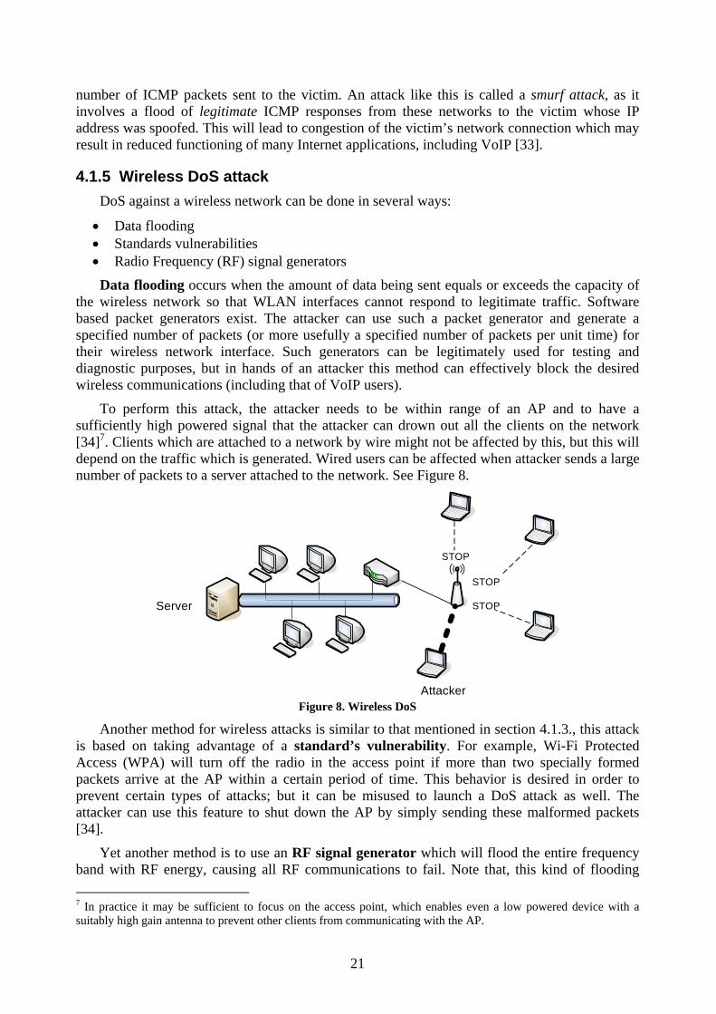
21
number of ICMP packets sent to the victim. An attack like this is called a smurf attack, as it involves a flood of legitimate ICMP responses from these networks to the victim whose IP address was spoofed. This will lead to congestion of the victim’s network connection which may result in reduced functioning of many Internet applications, including VoIP [33].
4.1.5 Wireless DoS attack DoS against a wireless network can be done in several ways:
• Data flooding • Standards vulnerabilities • Radio Frequency (RF) signal generators
Data flooding occurs when the amount of data being sent equals or exceeds the capacity of the wireless network so that WLAN interfaces cannot respond to legitimate traffic. Software based packet generators exist. The attacker can use such a packet generator and generate a specified number of packets (or more usefully a specified number of packets per unit time) for their wireless network interface. Such generators can be legitimately used for testing and diagnostic purposes, but in hands of an attacker this method can effectively block the desired wireless communications (including that of VoIP users).
To perform this attack, the attacker needs to be within range of an AP and to have a sufficiently high powered signal that the attacker can drown out all the clients on the network [34]7. Clients which are attached to a network by wire might not be affected by this, but this will depend on the traffic which is generated. Wired users can be affected when attacker sends a large number of packets to a server attached to the network. See Figure 8.
STOP
STOP
STOP
Attacker
Server
Figure 8. Wireless DoS
Another method for wireless attacks is similar to that mentioned in section 4.1.3., this attack is based on taking advantage of a standard’s vulnerability. For example, Wi-Fi Protected Access (WPA) will turn off the radio in the access point if more than two specially formed packets arrive at the AP within a certain period of time. This behavior is desired in order to prevent certain types of attacks; but it can be misused to launch a DoS attack as well. The attacker can use this feature to shut down the AP by simply sending these malformed packets [34].
Yet another method is to use an RF signal generator which will flood the entire frequency band with RF energy, causing all RF communications to fail. Note that, this kind of flooding 7 In practice it may be sufficient to focus on the access point, which enables even a low powered device with a suitably high gain antenna to prevent other clients from communicating with the AP.

22
may also be generated by microwave ovens or mis-configured devices which generate RF energy [34], along with other devices which utilize this same band, such as Bluetooth devices. However, such an attacker can be located because of the energy which they need to output.8
4.1.6 Countermeasures for flooding attacks against VoIP Network Infrastructure
Many solutions exist for defending a network against various DoS and DDoS flooding attacks, but there is no general solution which solves all problems. Therefore, the best defense is to strive to minimize the impact on VoIP devices, network components, and servers in case of such attacks [33]. Many types of network equipment can be configured to resist the most basic DoS and DDoS methods which attackers use. Cisco (one of the major router vendors) offers some recommendations against DDoS attacks [35]. (Other vendors have similar recommendations.) Three of their recommendations are:
1. Use the IP verify unicast reverse-path [35] interface command on the input interface on the router at the upstream end of the connection. This feature examines each data packet received as input on that interface. If the source IP address does not have a route in the Cisco Express Forwarding (CEF) tables that point back to the same interface on which the packet arrived, the packet is dropped.9
2. Filter all IP addresses allocated for private internet address space using Access Control Lists. (This assumes that the network is not using one of the address ranges which is being filtered!)
3. Use Committed Access Rate (CAR) to limit SYN and ICMP packets. Rate limiting is a mechanism that allows the network to run in a degraded manner, but still allows some degree of proper functioning when the device is receiving a stream of DoS attack packets as well as actual network traffic.10
Further information on how to prevent DoS attacks against Cisco equipment can be found at [35].
Another suggestion is to harden VoIP phones and servers regardless of the particular vendor:
• Change all default passwords and remove all guest and non-essential accounts. • Unnecessary services (such as telnet, HTTP, …) should be disabled.
The device and its operating system must be kept up to date with the latest patches and/or firmware. This requires developing strategies and policies for keeping up to date with patches. However, a large number of devices which will be used for VoIP services will not regularly be shutdown; hence software updates will need to take place without requiring that the device be rebooted or in some cases even updated while the device is in use.
Virtual LANs (VLANs) can be used to separate network domains logically on the same physical subnet. Creation of VLANs can be a component in protecting core VoIP servers and devices against most common DoS traffic, such as worms and viruses [33].
For wireless LANs, the best type of protection is gained through layered security or by defense in depth (see Figure 9). (Note that this is true for all LANs!) Thus even if an attacker gets
8 Of course it is possible with many interferers to generate sufficient background interference that communications is impossible, while still only transmitting what looks (at first) like legitimate traffic and at ”reasonable” power levels. This is the multiple RF source analogous to a DDoS attack. [GQMJr] 9 Note that this is ingress filtering, which results in Mobile IP v4 nodes having to do bi-directional tunneling. 10 In this case a reduced rate of SYN packets will be permitted through the router – potentially reducing the performance of HTTP connection attempts.

23
through one barrier, he or she might not get through the next barrier. For example, if an attacker has gained the information needed to configure his machine for WPA authentication; he or she still might need a network user account [34].
WPA wireless connection encryption
Network-Based user authentication
Access Control Lists used for each resource
Attacker
Barrier
Figure 9. Layered security for a WLAN
4.2 VoIP Network Eavesdropping
4.2.1 TFTP Configuration File Sniffing Most hardware IP phones rely on a Trivial File Transfer Protocol (TFTP) server to download
their configuration file after powering on. This file often contains passwords that can be used to connect directly to the phone and administer it. If an attacker has somehow gained access to the network and is able to perform TFTP sniffing, then this attacker simply watches for traffic on UDP port 69 (which is the default TFTP service port) {using a packet capture tool}. These tools (packet sniffers such as tcpdump11 and Wireshark12) help the attacker to discover the name of the configuration file. After the names of existing files on the TFTP server are identified, they can be downloaded directly from the TFTP server with a simple command [33]. If these files contain plain text usernames and passwords the attacker learns information which can be used to expand their attack. It should be noted that in some cases TFTP traffic sniffing is not even necessary as for some VoIP telephone vendors as the format of the file name is known and the file name includes the MAC address of the phone. Thus it is enough to know the MAC address of the phone, then just ask the server for the configuration files.
4.2.2 Number Harvesting and Call Pattern Tracking Number harvesting can help an attacker to gain sufficient information to build a database of
their target’s calling habits, which later can be used for more advanced VoIP attacks; such as signaling manipulation and Spam over Internet Telephony (SPIT). Or this information could be used directly by a competitor.
The easiest way for passive number harvesting is to sniff all SIP signaling traffic for UDP and TCP port 5060 and to analyze the From: and To: header fields. An easy way to perform this sniffing is to use the Wireshark packet sniffer. Tools such as Voipong13 (among others) can be used for logging all the calls from and to various IP addresses. This process can even be automated. Again, the attacker can use Wireshark to see the actual phone numbers or SIP URI’s involved in each call [33]. Note that if the SIP UAs have used S/MIME it may not be possible to see some of the desired data; suggesting that S/MIME should be used!
11 http://www.tcpdump.org 12 http://www.wireshark.org 13 http://www.enderunix.org/voipong/

24
4.2.3 Call Eavesdropping VoIP call eavesdropping requires access to the network, but we assume that an attacker has
such access. In this case he/she can use Wireshark or other tool to analyze RTP streams and to record their payload, for example to generate an audio file of the complete session.
4.2.4 TFTP Sniffing Countermeasures TFTP is simple and insecure by nature and there are not many options for securing the
communications channel. One option is to create a separate VLAN for the phones to communicate with the TFTP server. Another solution is to encrypt the passwords and usernames which would otherwise be sent as plain text in the TFTP configuration file. Another solution is to encrypt the entire file, but this requires that the device have the key needed to decrypt this file. This third method is implemented in some commercial IP phones. For example, a public/private key pair could be programmed into the device when it is manufactured.
4.2.5 Number Harvesting and Call Pattern Tracking Countermeasures Signaling encryption either on the network layer with IPsec or on transport layer using SIP
TLS (SIPS) may mitigate snooping on user’s dialing patterns. However, there is still a risk that IP addresses can be retrieved from the RTP traffic since the IP, UDP, and RTP headers are not encrypted by SRTP (which is often used as the secure media transport protocol). Using separate VLANs for VoIP may help reduce the risk of simple signaling sniffing on the network and the (easy) interception of the RTP traffic [33]. In Figure 10, we can see various forms of security that can be applied to signaling streams across the various layers.
SIP security
Network layer
Transport layer
Application layerS/MIME
TLS
IPSec Figure 10. SIP security mechanisms on different layers
While VPNs can be used to hide the IP addresses used in the tunneled traffic, this does not hide the existence of the tunnels themselves. To perform traffic hiding of these is much harder and out of the scope of this thesis.
4.2.6 Call Eavesdropping Countermeasures Confidentiality of a VoIP conversation may be achieved by encrypting the RTP media
stream. This can be done in several ways. One approach is at the network layer with IPsec (VPN) as Raúl Garcia [27] suggests, and another is via media encryption on the transport layer with SRTP or ZRTP [33]. SRTP is most common protocol used for this purpose and is supported by several hard phones such as Avaya 9600-series14, Linksys SPA 900-series15, and Snom 300-
14 http://www.avaya.com 15 http://www.linksys.com

25
series16, and firewall manufacturers such as inGate17. In cases when firewalls are not SRTP friendly different techniques can be deployed such as Simple Traversal over NATs (STUN), Traversal Using Relay NAT (TURN), SBCs, and other proprietary solutions.
4.2.7 Virtual Private Networks: IPsec and TLS Creating a Virtual Private Network (VPN) using IPsec or TLS is one way of securing the
data flowing over insecure networks (such as the Internet). A brief presentation of these technologies follows.
VPN technologies are mainly used by companies that want to provide secure access to the company’s network for their remote users. The Virtual Private Network Consortium (VPNC) describes a VPN as a private data network which uses an existing communication infrastructure while maintaining privacy by making use of a tunneling protocol and security procedures [44]. VPNC recommends two technologies for securing VPNs: IPsec and TLS.
IPsec [45] is designed to provide interoperable, high quality cryptographically-based security for IPv4 and IPv6. It includes security services such as:
• Access control • Connectionless integrity • Data origin authentication • Protection against replays • Confidentiality (via encryption) • Limited traffic flow confidentiality
In order to meet these objectives there are two security protocols in IPsec. These are Authentication Header (AH) and Encapsulating Security Payload (ESP) which can be used together with cryptographic key management procedures and protocols. AH provides integrity protection and data origin authentication; while ESP may provide encryption and/or integrity protection. Both of these protocols may be used in combination or separately to achieve the desired set of security services for IPv4 or IPv6 [45].
The TLS protocol [8] has a primary goal to provide privacy and data integrity between two communicating applications. The protocol consists of two layers: the TLS Record Protocol and the TLS Handshake Protocol.
The TLS Record Protocol is layered on top of some reliable transport protocol (e.g. TCP). It provides connection security that has two basic properties:
• The connection is private • The connection is reliable
A TLS Record is used for encapsulation of higher level protocols, such as the TLS Handshake protocol. Protocols such as the TLS Handshake protocol allow the authentication of both server and client. It should be noted that many applications do not do bi-directional authentication. The handshake protocol also allows the server and client to negotiate the encryption algorithm and cryptographic keys before data transmission [8].
The TLS Handshake Protocol provides connection security that has following basic properties:
• Nodes can be authenticated by using cryptography
16 http://www.snom.com 17 http://www.ingate.com

26
• The negotiation of a shared secret is secure and protected even from attackers which may be placed in-the-middle of the connection (i.e., a so-called man-in-the-middle attack – se the next section).
• The negotiation of secrets is reliable. If an attacker tries to modify the negotiation communication, then he will be detected by the parties
Both IPsec and TLS are application protocol independent. This means that higher level protocols can be layer on top of these protocols transparently (see [8] for details of this for TLS).
4.3 VoIP Network Interception (Man-in-the-Middle)
4.3.1 ARP altering The most common means of carrying out a man-in-the-middle interception is by Address
Resolution Protocol (ARP) cache poisoning. ARP is used to map MAC addresses to IP addresses. An attacker changes the contents of the ARP cache in order to place himself between the two hosts which are involved in a VoIP session. Each of these hosts thinks that the attacker is the other legitimate party (Figure 11) and in this way the attacker acts as a gateway, silently forwarding and monitoring the traffic between two tricked hosts.
Interceptedlink
Host 1 Host 2
Man-in-the-Middle Figure 11. Man-in-the-Middle concept
Once the attacker is in this position he or she can conduct a number of other attacks [36]:
• Eavesdrop the conversations and inspect any packet • Cause DoS • Modify the conversation by excluding, replaying, and/or inserting media • Redirecting the sending party to another receiving party
A man-in-the-middle attack will most likely be performed by an attacker who already has access to the internal network (which we assume that he or she has gained in some way). As mentioned earlier for other attacks, many tools exist which can be used to perform ARP cache poisoning, such as: Cain and Abel18, Ettercap19, and Dsniff20. These powerful tools were developed to help network administrators, teachers, security professionals, and so on, and are intended for use for ethical reasons. In the hands of an attacker they can be used to cause a lot of damage. The man-in-the-middle attack is not VoIP specific, but can be used to cause a lot of damage to all kinds of applications on the network.
18 http://www.oxid.it/cain.html 19 http://ettercap.sourceforge.net 20 http://www.monkey.org/~dugsong/dsniff/

27
4.3.2 Network Man-in-the-Middle Countermeasures It is possible to manually enter MAC address to IP mappings into a static ARP table for each
host on the network; thus avoiding the need to reply upon ARP traffic on the network. As this is very time consuming, it is much easier to apply port security settings in the switch than make manual ARP entries for every possible host on the network. However, this method may be suitable for critical workstations and servers (VoIP proxy, gateway, DHCP, and so on) [33].
In some cases, segmenting of the network into VLANs, can contribute to a reduction of the risk of ARP spoofing [33]. However, for reasons described earlier it may be neither practical nor desirable to use VLANs.
Session encryption on various layers is another form of protection against man-in-the-middle attacks. An IPsec VPN can be used on the network layer and SRTP or ZRTP used on the application layer [33]. TLS may be used as a countermeasure against man-in-the-middle based SIP VoIP signalling attacks [36]. All of these techniques can provide end-to-end integrity checks, thus preventing against and detecting man-in-the-middle attacks. (Note that these protocols do not automatically do so, but must be configured and deployed properly – this means that proper configuration of the network infrastructure and end-points will be important elements of any security plan.)
Tools for ARP poisoning detection exist. An example of such a countermeasure is arpwatch. In case of an attack, arpwatch will generate an alarm and report changes via email or a syslog entry. More information about arpwatch can be found in [37].

28
5 VoIP Session attacks Manipulation of SIP messages is a well known technique underlying a number of types of
attacks. An attacker must (by some means) get access to the network. For the scope of this thesis we assume that the attacker has the needed access.
5.1 Signalling Manipulation SIP signalling attacks may consist of:
• Tearing down calls with a faked BYE/CANCEL message. • Registration hijacking where an attacker impersonates a valid UA to a registrar and
replaces the legitimate registration with its own address. • Registration removal. All SIP phones register themselves with their SIP Registrar when
they are rebooted. If this REGISTER message is not successfully received, then important SIP phones may not be able to receive calls. However, this does not prevent the attacked phone from making calls.
• Registration addition lets a user redirect phone calls to multiple devices in different places such as office, lab, conference room, and so on. The first phone which is picked up answers the call. In a registration addition attack an attacker may register many UAs which will ring simultaneously causing irritation and confusion. Or the attacker can simply add a phone over which he or she has control, to hijack all incoming calls (assuming that this phone always answers first – which it might do by automatically answering all calls).
• Server impersonation involves an attacker tricking UAs into thinking that they are communicating with the legitimate SIP server; when they in fact are communicating with an attacker impersonating the server. In this case, the attacker gains control of the entire signalling of incoming and outgoing calls.
5.2 Signalling Manipulation Countermeasures Some authors; [33] and [36], propose that TCP should be used for SIP signalling rather than
UDP. This is because TCP provides sequence numbers. This feature makes it more difficult for an attacker to trick a SIP proxy into accepting a spoofed registration. However, TCP must be used on all SIP phones communicating with the SIP proxy to be effective. Furthermore, if TCP is used, then TLS may be combined together with it -- allowing encryption; thus providing confidentiality and integrity over each hop in the signalling path [36]. However, TCP is not accepted by all SIP phones and other devices, hence those without TCP will still be vulnerable to signalling manipulation attacks.
Other protocols such as S/MIME may be used to protect SIP signalling messages regardless of whether UDP or TCP is used. However, S/MIME lacks replay protection.
Recently, IETF accepted Datagram TLS (DTLS) [38] for secure signalling over UDP. DTLS is in many ways similar to TLS, but was adjusted to suit UDP. Therefore DTLS may in the future be used for protection of SIP messages sent over UDP. For more details and implementation of DTLS see [39].
However, trying to obtain “security through obscurity” by using other than well known ports, such as the default SIP port 5060, offers very limited protection [33].

29
5.3 Media Manipulation Once an attacker is in position between two UA’s he/she may be able (with help by various
tools) to collect, insert, and to mix new audio into an active conversation. This attack is based on RTP message manipulation. The idea is to insert or mix sounds in so that one or both parties hear disturbing noise, words, or other impropriate sounds. This kind of attack can cause a lot of damage. It can irritate, insult, and create confusion. It may undermine reliability and credibility of both individuals and enterprises.
5.4 Media Manipulation countermeasures RTP manipulation can be mitigated by encryption and authentication of the audio stream. If
the audio is encrypted and authenticated, then it is not possible to insert and mix in new sounds in an ongoing VoIP conversation. Even if new audio were inserted in some way (that passed the authentication test) it would sound just like noise after decryption.
One solution is to use SRTP to provide end-to-end encryption and authentication between two IP-phones. Because MIKEY offers perfect forward secrecy it should be used to provide the SRTP key exchange [43]. However, SRTP does not encrypt RTP headers which are sent in clear text. Data such as payload type, synchronization source identifier, and timestamp are exposed to an attacker [18]. This may allow traffic analysis by collecting information from the RTP headers and extensions. This information can later be used for spam over internet. If the protection of RTP headers is a must, then IPSec is proposed as an alternative in [18].
When RTP packets are collected for analysis, Wright, et al. [49] claim that it is possible to a large extent, to identify phrases spoken within a VoIP call secured with SRTP and where the audio was encoded using variable bit rate CODECs. This is possible by analyzing the lengths of the encrypted VoIP packets. These authors argue that in the standard specification for SRTP, the cryptographic layer when it encrypts packets does not pad or otherwise alter the size of the original RTP payload. One solution to this may be to pad packets to a common length or at least to coarser granularity. For details on this issue, more information is available in [49]. It is important to note that this does not apply to CODECs which do not do silence suppression and use a fixed data rate.
Properly configured LAN switches and VLANs may make insertion of false RTP packets even more difficult, but still possible.
Use of VoIP/SIP aware firewalls can be a good idea, but to place a VoIP/SIP firewall in front of all VoIP phones might not be practical in terms of scalability. However, firewalls should be used when VoIP traffic is exchanged with a public network. A SIP firewall can monitor incoming and outgoing RTP packets and detect some audio insertion /mixing attacks [33].
Another means to secure RTP traffic is based on an IPsec VPN. In this approach a VoIP session is established by the SIP server before an IPsec tunnel is built to provide end-to-end security of the media traffic. However, the IPsec protocols add overhead to the voice packets. To solve this, IP header compression may be used. Due to the advances in microelectronics, IP header compression and encryption may be performed at the UAs. After a successful initiation of a SIP session in which the MIKEY message for IPsec has been included, an end-to-end VPN tunnel is established between the two UAs using Encapsulating Security Payload (ESP) in tunnel mode. This protects the entire inner IP packet. IPsec secures the confidentiality of the session’s media contents [40].

30
An alternative to these two existing solutions may be to send RTP media over DTLS. DTLS would offer comparable security and it would be easier to implement than IPsec. However, this solution is still a work in progress and it is not yet sufficiently mature for the market.
5.5 Signalling and Media Manipulation Summary A good means to provide secure signalling in order to enable end-to-end protection of media
flow is to use TLS over TCP to secure the SIP signalling, rather than S/MIME. TCP uses sequence numbers which makes it harder to insert spoofed registrations and TLS provides encryption for confidentiality and integrity over each hop in the signalling path. Unfortunately S/MIME does not provide any protection against replay attacks, thus necessitating further protection. It should be noted that S/MIME provides end-to-end security of SIP signalling which TLS does not, but due to lack of replay protection in S/MIME; TLS over TCP is preferred for SIP signalling protection.
For end-to-end media protection; MIKEY should be used to provide SRTP key exchange since it provides perfect forward secrecy. RTP media end-to-end protection should be provided by SRTP. SRTP is preferred over IPsec since it makes VoIP applications less dependent on IPsec support in the end-device and it secures the RTP traffic of each media stream in a session with its own key [43]. However, SRTP does not encrypt RTP headers which are sent in clear text, thus allowing attacker(s) to perform traffic analysis by collecting information from these headers. IPsec may be necessary to solve this problem.
It has recently been shown that audio encoded using variable bit rate CODECs and encrypted with length preserving encryption such as SRTP, may allow attackers to identify phrases within a VoIP call. The lengths of encrypted VoIP packets lead to this vulnerability. Therefore, padding of packets to common length may be a solution to this problem. Another means of reducing the effectiveness of this analysis is to use CODECs which generates fixed sized blocks and to turn off silence suppression (i.e., to continuously transmit packets whether there is actually audio/video content to transmit or not).

31
6 Link change At a site, e.g., a large company or campus, equipped with many access points belonging to
the same subnet, many handovers that will occur during a session can be handled by link layer mobility mechanisms. This is true only if these kinds of handovers do not result in a change of IP address. If the user roams between several wireless APs, as shown in Figure 12, then if they are attached to different LANs or between different link technologies this may result in a change of IP address (unless Mobile IP is used).
WLAN 1(Subnet 1)
WLAN 2(Subnet 2)
Internet
LAN
AP 1 AP 2
Alice Bob
SIP Server 1 SIP Server 2
SIP
Sig
nalli
ngS
IP S
ignalling
SIP S
ignall
ingSIP Signalling
SIP Signalling
On the move
RTP Media
Figure 12. Alice moves from WLAN 1 to WLAN 2
As we mentioned earlier, handovers between different LANs are referred to as horizontal handovers and handovers between different technologies are vertical handovers. In order to maintain an ongoing session when these kinds of layer-3 handovers occur, different mobility mechanisms are needed. One widely deployed mechanism is Mobile IP. Different versions of Mobile IP exist. SIP mobility is another mechanism which is of interest for the scope of this thesis. This chapter will examine each of these potential mechanisms.
6.1 Mobile IPv4 Mobile IPv4 is described in [41]. It is an IETF standard protocol for IPv4 which is designed
to allow transparent routing of IP datagrams to mobile devices in the Internet. In addition, Mobile IPv6 exists for IPv6 and we will focus on this IPv6 for the remainder of this thesis. Some of the main differences between MIPv4 and MIPv6 can be seen in Table 1.

32
Table 1. Some differences between MIPv4 and MIPv6 Mobile IPv4 Mobile IPv6
• IPv4 addresses are 32-bits long. • IPv6 addresses are 128-bits long. • Uses tunnel routing to deliver data
packets to Mobile Nodes. • Uses tunnel routing and source routing with
IPv6 type 2 routing headers. • Mobile IPv4 may use Foreign Agents
(FA) for Mobile Node movement detection and it can use FA to decapsulate data packets destined to a mobile node’s care-of address. However, MN can also use co-located care-of-address to decapsulate packets itself, thus FA is not needed.
• MIPv6 does not use Foreign Agents. The Mobile Node decapsulates data packets destined to its care-of address itself and uses Router Advertisements for movement detection.
• Route Optimization is an extension to the protocol.
• Route Optimization is a fundamental part of MIPv6.
• Reverse Tunnelling is an extension to the protocol.
• Bi-directional tunnelling is part of the core protocol.
• Uses one Home Address. • Uses a globally routed Home Address and link-local Home Address.
6.2 Mobile IPv6 Mobile IPv6 (MIPv6) [42] is a protocol (similar to MIPv4, but with enhancements and
adaptation to IPv6) that allows nodes to remain reachable while roaming in the IPv6 Internet. All mobile nodes possess a home address by which they are reachable regardless of their current attachment point to the Internet. When away from its home network, each mobile node is also associated (bound to) a care-of-address (COA), assigned by the visited network. The COA provides information about the mobile node’s current attachment point. All IP packets destined to the node’s home address will be forwarded transparently to the COA of the node, if it is not at home. Without mobility support such this or similar, maintenance of an on-going session would not be possible due to the change in IP address [42].
While attached to a link in a foreign network, the mobile node registers its COA with a router on its home network, asking this router to function as its “home agent” (HA). This registration by the mobile node is done by sending a “Binding Update” (BU) message to the home router which in turn replies with Binding Update ACK message.
Two possible modes for communication between a mobile node (MN) (with a care-of-address) and a corresponding node (CN) (any node communicating with a mobile node) exist [42]: Bi-directional tunnelling and Route optimization.
Bi-directional tunnelling does not require MIPv6 support from a correspondent node and it works even if a mobile node has not registered its current COA with the correspondent node. All data packets destined to the mobile node, wherever on the Internet it might be, are tunnelled to it via its home agent. Packets from the mobile node to the correspondent node are reverse tunnelled to the home agent and forwarded to the correspondent node by the home agent. In this way the correspondent node does not know (or need to know) the current address of the mobile node. This means that only the HA needs to receive binding updates with a COA from the MN. These BU’s are sent over IPSec or a VPN tunnel and are therefore authenticated and secure. Since the CN is not aware of the MN’s COA it can not easily determine where the MN is located and therefore this mode provides some location privacy for the MN. However, if MN is far away from its home network and is close to CN, then the signalling and communicating path may be

33
unnecessary long. Tunnelling also adds overhead to all the data packets, adds traffic load on the HA, and may result in inefficient routing that may lead to unacceptably high packet delays. However, these problems can be avoided by using route optimization.
Route optimization. To perform route optimization, registration of the mobile node’s current COA at the correspondent node is required. Packets from the correspondent node can be routed directly to the mobile node’s COA without any intermediaries. This routing to the mobile node’s COA follows the shortest path (or best path as determined by the routing tables along the way). Congestion at the mobile node’s home agent and home network is avoided in this way, as the packets between the mobile node and correspondent node need not go via the user’s home network (unless one of MN or CN is in this network – but in either of these cases there is no route optimization as the route will already be optimal; therefore, for the remainder of the discussion we will assume that neither case is true). Furthermore, the impact of any subsequent failure of the home agent or networks on the path from and to the HA can be avoided. However, this approach requires that the correspondent node implements binding updates. It also has some negative location privacy implications as the CN knows where the MN is currently attached (in terms of its IP address) and this enables some additional traffic analysis.
J.-O. Vatn discusses in [43] some security issues for layer-3 schemes and especially for MIPv6 with route optimization which are of interest for this thesis. These issues are:
• No global authentication infrastructure: When Alice is moving and wants to inform her corresponding node (used by Bob) of her new COA with a BU, this BU message needs to be authenticated in order to prevent attackers from redirecting traffic from Bob to some other node. In MIPv6 with route optimization this BU is protected without relying on the existence of a global authentication infrastructure. A Binding management key (Kbm) used to authenticate the BU is created based on the same authentication infrastructure as used in establishment phase of a secure VoIP call.
• Verifying “ownership” of home address: When Alice sends a BU to Bob with her new home address/care-of-address she would like Bob to insert a source routing entry in his binding cache. However, Bob needs to verify that Alice really is able to receive data via her new address. In MIPv6 with route optimization this is done by performing a home address test. In this test, Bob sends a Home Test packet (HoT) containing a home address token to Alice. This token is part of the Kbm which we mentioned earlier. The HoT packet will reach Alice, if she is either at home or this packet can be tunnelled (with or without IPsec) to her COA. This gives some assurance that Alice really controls her claimed home address. However, there is still a risk that an attacker may intercept the HoT packet on its way to Alice, but such a spoofing attack may be possible even without mobility support, thus MIPv6 does not reduce security from that point of view.
• Verifying access to COA: Risk of attackers launching a DoS attacks against some addresses on the internet exists. To cope with this risk, MIPv6 lets Bob send a care-of test packet (CoT) to Alice’s claimed COA, containing a COA token. This COA token is used together with the home address token when forming the Kbm.
• No multiplication of traffic: In order to avoid certain DoS attacks where an attacker can send a single packet to a node, triggering that node to respond with multiple packets, Alice will need to send two separate packets Home Test Init (HoTI) and Care-of Test Init (CoTI) to Bob to trigger him to send the corresponding HoT and CoT packets.
The home test and care-of test can be done in parallel and do not need to be done sequentially. For an example of messages that are exchanged, see Figure 13 - where events represented as dashed lines do not need to affect the handover latency.

34
Alice HA Alice Bob
1:Binding Update
2:Binding Ack
3:Home Test Init3:Home Test Init
4:Home Test (home keygen token)4:Home Test (home keygen token)
5:Care-of Test Init
6:Care-of Test (care-of keygen token)
7:Binding Update
8:Binding Ack
Figure 13. Binding Update message exchange during Alice’s handover in MIPv6 [43]
6.3 SIP Mobility During a SIP based VoIP call, any of the participating parties may change their preferences
during the call [3]. Within the scope of this thesis, this is interesting since if, say Alice, suddenly changes her IP address due to a handover from one WLAN to another during an on-going VoIP session; she can send a re-INVITE message to Bob instead of starting a new session. The re-INVITE message can be sent as soon as the new IP address on the new network is acquired. This re-INVITE message will include the new IP address of her device(s) to which Bob’s UA should continue sending RTP (or SRTP) datagrams and maintain other preferences that their UAs agreed upon earlier (or at the start of the VoIP session). The delay or interruption of the VoIP call is only as long as the time it takes for Alice to obtain a new IP address and the time it takes for Bob to receive this new address [43]. At the present time, this delay can be of the order of several seconds, which is not acceptable for real-time media. However, this delay may be significantly decreased. A major contribution to this delay comes from Alice’s behaviour when she acquires a new IP address; as she performs Duplicate Address Detection (DAD) by probing to see if the acquired address is already in use. After the probe is sent she waits to see that no reply is received. J.-O. Vatn describes in his doctoral dissertation [43], three alternatives to minimize the delay caused by DAD in IPv6: Skip DAD, Pro-active DAD using a new access router, and DAD using a new access router after handover.
Skip DAD: DAD is actually a recommendation, rather than requirement. J.-O. Vatn believes that the probability of address conflict is minimal and that it can be resolved reactively (Note that this is especially true in the case of IPv6 – when using auto configuration.). In other words, Alice can perform DAD after she has started using the new IP address. By doing so, time may be saved during the handover. (Note that in IPv6 the probability of a duplicate address is very small if the MAC address is being used to derive the low order bits of the interface’s IPv6 address – since if you use the manufacturer’s programmed MAC address it should be unique.)
Pro-active DAD using a new Access Router (AR): Given that Alice is able to contact the new AR using Candidate Access Router Discovery (CARD) before performing a handover, she

35
could ask the new AR to test her new address by consulting its neighbor cache instead of “probing” the address. If Alice needs to send data before DAD is successful, then she can then use an encapsulation mechanism which allows this, see details in [43].
DAD using a new AR after handover: The previous alternative can be useful even if Alice is not able to contact the new AR in advance. In that case, immediately after the handover she would get a response about the address from the new AR, this is faster than waiting for an answer not to appear.
6.4 Handover procedure This section gives a short presentation of the horizontal handover procedure in general. What
happens just before a handover and what happens during a handover will be described. Some assumptions which may affect maintenance of an on going VoIP session are [43]:
• Header compression can be used to improve performance by better bandwidth utilization, but we will focus on high speed networks therefore we do not need to consider this question farther.
• Bandwidth reservation and QoS. We do not consider bandwidth reservation or require that VoIP traffic will be given priority over other traffic, as we here will assume that there is sufficient bandwidth for all traffic including VoIP.
• Availability of global IP addresses. In IPv6 addresses are 128 bit long, so the availability of addresses will not be considered a problem; since we can assume that address availability is almost unlimited (i.e., it is at least proportional to the number interfaces that can connect to networks using IPv6). We therefore assume that when the user is visiting in a foreign network that they will be provided with a globally routable address. (This removes the need for NAT; which should generally be unnecessary in IPv6.)
• Use of firewalls or their existence will not be considered (i.e., they are explicitly outside the scope of this thesis project).
• We assume that every corresponding node is MIPv6 compatible and that it supports route optimization.
As noted above, many of these questions will not be considered further, since we will assume that they do not present an obstacle that is relevant for this thesis.
Other questions such as:
• Whether Alice has a roaming agreement with new WLAN(s) that she visits and how her visit should be billed will not be considered. We assume that she has access to the visiting WLAN(s) and that she does not have to do anything special (such as perform a login via a web interface) to establish access via this network access point.
• Which WLAN Alice should attach to if several WLANs exist in the same area and on what basis she would decide to which one she will attach will not be considered. We will simply assume that the AP with the strongest received signal strength will be used.
Furthermore, we have limited the IP layer handover procedure to consider only what happens when a user’s terminal has a single WLAN interface and when the handover occurs between two different APs belonging to different subnets. A similar scenario could be extended to cover the vertical handover procedure (which occurs during handovers between WLAN and UMTS (3G) networks).
In Figure 14 we can see a possible handover procedure for MIPv6. In this figure we have chosen not to include Authentication and Authorisation (this step would occur between Duplicate

36
Address Detection (DAD) and the Register New CoA). We will not consider Authentication and Authorization, as we assume that Alice is authorized to access to the new WLAN.
Movement Detection
Router Discovery
Address Configuration
Duplicate Address Detection
Register New CoA
Binding Update
Completion
Figure 14. MIPv6 Handover Procedure
6.4.1 Before handover Initially, we assume that Alice is attached to her home WLAN and that Bob is also attached
to his home LAN (Figure 12). In order to make a VoIP call to Bob, Alice uses a MiniSip UA. She may first register her current location (IP address) with her SIP registrar. Later Alice’s UA follows the standard SIP signalling procedures in order to make a call to Bob. (Here we have assumed that Bob’s UA has already registered earlier with Bob’s SIP proxy.) These procedures have been described in section 2.2.1. For secure SIP signalling Alice uses TCP and TLS.
Since Alice uses MiniSip we assume that the calling parties use MIKEY/Diffie-Hellman in order to setup a secure phone call and that SRTP is used to protect the RTP media flow during the call. During the call setup parties may use SDP to agree on preferences for the call (CODEC, ports, and so on). Alice and Bob both use MIPv6 with route optimization for mobility support if they need to roam between different networks. Once Alice and Bob have agreed upon their SIP session preferences, we assume that they have a secure ongoing VoIP session.
6.4.2 Upcoming handover The decision of when to make a handover is not always an easy task. When Alice is moving
away from WLAN AP1 the signal from that AP decreases with distance (and due to other factors). At one point she will potentially enter the cell of an AP belonging to the WLAN2 (i.e., AP2) and this signal will become stronger as she approaches this access point. At some point Alice must decide when to perform the actual handover. This scenario can be extended to the case when a mobile node with dual interfaces is attached to a WLAN, but needs to handover to a 3G network due to the poor network conditions and/or degradation of the voice quality. (Note that the situation for a handoff when the device has dual interfaces is fundamentally different than the case where the device has only a single interface -- which can only be attached to a single network at a time, thus it can not search for other networks while maintaining communications via the currently associated access point.)
Daniel Yunda proposes in his thesis [46] an algorithm that may provide information about the correct time for a successful handover decision. Most of the handover algorithms in today’s wireless systems are primarily based on signal strength measurements. Yunda proposes that additional parameters should be added to the algorithm in order to improve the accuracy and reliability of the handover decision. Such parameters could be: location information, noise or interference, packet loss, or number and pattern of link layer retransmissions. Some additional factors such as: cost, terminal speed, or user preferences may also be considered since for many VoIP users cost savings may be the main reason why they are using VoIP.
We assumed earlier that use of (W)LAN for VoIP does not need to be expensive, but that the use of a 3G network costs a certain amount of money per minute. So an early handover from WLAN to the 3G network will not result in a loss of packets and there will not be any extra delay, but it will simply cost more money. Similar behaviour may occur for a handover in opposite direction which is done too late (see Figure 15). It is important that algorithms for successful handover properly address the case of vertical handover which is done too late from

37
WLAN to 3G or from 3G to WLAN too early, as these both may result in loss of packets and extra delay. Early handover to 3G from WLAN and late handover from 3G to WLAN only leads to an increased cost for the user. This observation (by Prof. G. Q. Maguire Jr.) was a key part of the earlier planning of Yunda - as one can now make a quantative cost analysis of these costs. Maguire has further pointed out that in the case of a flat rate 3G subscription – there is no economic cost in making these handovers as long as the total usage (in terms of packets) does not exceed the user’s monthly allocation (i.e., the maximum amount of traffic included in the flat rate tariff for the month). Therefore the introduction of low cost flat rate services in Sweden fundamentally changes the goals for such handoffs!
Early OK Late
Predifined voice quality treshold
Time
Network condition
Handover execution
Quality window Figure 15. When to make a successful handover (adapted from Figure 1.1. in [46])
Yunda’s function takes parameters for: signal strength, packet loss, delay, jitter, layer-2 retransmissions, transmission rate, and user preferences and combines them into a “handover score” which indicates the correct time for the handover. If the handover is performed at the correct moment, then both service quality improvements and cost savings can be realized. The next section looks in detail at this handover process.
6.4.3 Handover process In this section, a brief description of a potential handover process is described using ideas from [47]:
• Movement detection. When Alice detects that the link quality to her AP is decreasing (based upon increased error rate, increased rate of retransmission, decreased signal strength, …) she may start to search for new APs in her vicinity to associate with. In MIPv6 it is generally the MN’s responsibility to detect movement between networks. In order to discover if the MN’s Current Access Router (CAR) is still bi-directionally reachable the MN performs Neighbour Unreachability Detection. This detects the failure of the neighbour or the failure of the forward communication path to the neighbour. This detection requires positive confirmation that packets sent to a neighbour are actually reaching their destination and that they are being properly processed by its IP layer. Two sources for confirmation are used by Neighbour Unreachability Detection: (1) when it is possible, upper layer protocols confirm that the previously sent data is known to have been delivered or (2) when such confirmations are not possible, the node sends unicast Neighbour Solicitation messages that solicit Neighbour Advertisements as reachability confirmations from the next hop.

38
It should be noted that neighbour unreachability detection only works if the MN has something to send – this is done in order to reduce unnecessary network traffic. Therefore in the worst case, if the MN has no traffic to transmit it may not notice that it has moved out of its communication range to the current access point until it receives a unsolicited router advertisement from the new on-link router21. However, simply because the mobile node notices a new router advertisement does not guarantee that the MN should switch networks, but it may provide a hint that it should consider performing a handover.
• Router discovery. Router discovery occurs when mobile node receives an unsolicited router advertisement from the New Access Router (NAR). Each access router periodically sends such advertisements to a multicast addresses. Otherwise, MN will listen for a response to a router solicitation sent by MN itself. Which of these two occurs first depends on the link and network circumstances at the time of the potential handover. However, the receipt of a new unsolicited router advertisement does not necessarily indicate that a MN has changed networks. Thus Alice must decide when it best suites her, in terms of voice quality and/or cost, to change networks. If Alice’s WLAN interface senses that a handover is imminent, she may inform Bob so he can prepare him self by: • adjusting his play-out buffer to be larger to compensate for longer delays and higher
jitter [43]; • adjusting his CODEC to compensate for eventual packet loss caused by the
synchronization following the handover [17]; and • if possible, Alice could try to execute the handover during a time when both parties
are silent. • Care of Address configuration. To use the network, the MN must configure itself with an
IP address. In Mobile IPv6 the user has a permanent home IP address which is assigned to its home network. When the user is on the move he/she needs to configure his or her device’s interface with a Care of Address in order to use the visited network. To be able to generate this address when Mobile IPv6 is used as the mobility mechanism, the host router may use automatic address configuration. In this approach, the host uses a prefix contained in the router advertisement to which it appends an IP address based upon its 64-bit interface identifier22 in order to generate a globally routable IP address. Other means of acquiring the COA in MIPv6 include stateless DHCP, but this approach adds additional delay and overhead that is undesired.
• Duplicate Address Detection. As we mentioned in section 6.3, there are several solutions to reduce the delay required for DAD; as Vatn has proposed in [43].
• Registration of the New Care-of Address. In MIPv6, as soon as the COA is obtained and the network access granted, Alice will send a BU message to her HA to inform it of her new location. The HA will reply with a Binding Acknowledgement (BA). In addition, Alice will send a BU to Bob so he can continue sending packets to her directly. Future packets destined to Alice from Bob will be sent to her directly and not via her HA since MIPv6 with route optimization is utilized. If SIP mobility is utilized in order to maintain an on-going VoIP session, a SIP re-INVITE message will be sent to Bob upon a layer-3 handover enabling his UA to continue the on-going session with Alice without needing to start a new session. It is assumed that Alice can send upstream data to Bob immediately after acquiring the new
21 Note that this assumes that the device does not utilize the information it has from the access point (such as link layer beacons) – which might occur once every 100ms (which is more often than the roughly once per second of router advertisements). 22 Note that while the reader might generally think of the MAC address as being 48 bits in length, IEEE has expanded the potential MAC address space to 64 bits. There is a predefined way to convert a 48 bit MAC address to a 64 bit interface identifier.

39
COA, while Bob can start sending only after he has received the re-INVITE message. More details on SIP mobility can be found in [48].
• Binding Update Completion. After Alice has informed Bob of her new COA, Bob performs a Return Routability (RR) test in order to find out if the BU he receives is authentic and not from an attacker. This test uses a HoT and CoT (as described earlier in section 6.2), which are sent to Alice via the HA and the route optimized path (i.e. the shortest path) directly to her new COA. Once Alice has received a BA from Bob, the handover procedure can be considered as completed.
For more details on MIPv6 handover, see [47].
6.5 Link change: summary Mobile IPv6 and SIP mobility offer similar solutions to address layer-3 mobility, there
remains a question of which technique is most suitable for particular implementations [43]. As both my supervisor at Combitech and I want to learn more about Mobile IPv6, we agreed that MIPv6 should be used to provide mobility support for layer-3 handovers during the test phase.
Summary of the handover in the context of IPv6:
• Alice’s WLAN interface must decide when it is the correct time to attach to the foreign WLAN network. During the attachment process Alice’s terminal will associate with a new AP and obtain a new IP address, which becomes her UA’s new COA in this visited network.
• A BU will be sent from Alice to her home router and her correspondent node (the later will only occur - if there is an on going session in process). Once this BU is received all data packets destined for Alice’s home address will be routed to her current COA.
• With regard to the on going VoIP session; two different solutions can be used to redirect the RTP data flows: • SIP mobility using a re-INVITE message: Alice sends a SIP re-INVITE directly
to Bob using TLS as a transport protocol as soon as she obtains a new COA. If a protocol other than TLS is used, for example UDP, or if Alice and Bob require end-to-end protection of re-INVITE messages, then MIKEY can be used for authentication -- if it has already been used during the establishment phase of the call. This would prevent an attacker from redirecting a data stream, but will not affect the handover delay since credentials exchanged during the initial MIKEY handshake may be reused [43]. Alice can transmit packets immediately after receiving her new COA, but she would not be able to receive packets from Bob until he receives the re-INVITE message and reconfigures his settings for the session.
• MIPv6 with route optimization: Immediately after the CAO address is obtained Alice may send a BU to her HA and via this HA also to Bob (or even send a BU directly to Bob first). This first message, the BU, may be sent to Bob via Alice’s HA, but further traffic from Alice to Bob will be sent directly to him, since both parties support MIPv6 with route optimization. The reason why the BU should be sent to Bob via the HA is to ensure that the new address really comes from Alice and not an attacker.

40
7 Practical test We performed a set of general tests to evaluate if the security and mobility protocols are
sufficient to provide secure session mobility for VoIP. In our test we will utilize Mobile IPv6 together with MiniSip. Mobile IPv6 will provide mobility support for our MN, while MiniSip will provide security using TLS, DH/MIKEY key exchange and SRTP. OpenSIPS23 will be our SIP server as it is an open source implementation with plenty of features but mostly because it supports TLS and IPv6. We will use one HA, one MN, and one CN. We configured an IPv6 network with these components inside (see section 8.1.1).
We made these choices for the test network configuration, since as we described in previous chapters, Mobile IPv6 is a well known technique to provide mobility for mobile nodes. While MIKEY and SRTP are key management and media security protocols that can be used to secure VoIP sessions. TLS together with TCP can be used to secure the SIP signalling during the session establishing phase. We assume that the next hop in SIP proxy chain is trusted, thus we can safely use TLS without risking decreased security. MiniSip is used as the SIP user agent which can be used to make SIP VoIP calls. We selected MiniSip because it supports MIKEY, SRTP, IPv6, and was available for the computers which we used for our testing.
In our tests, we will made use of the above technologies in order to investigate if they provide the mobility and security required for VoIP sessions. The tests were conducted at Combitech AB’s VoIP test lab. In addition to the MN, CN, and HA, we setup SIP servers/registrars in order to create a suitable SIP network for our tests.
During this testing we want to perform three major sorts of tests: Functionality of the entities used for these tests, their performance, and the security offered by the implementations of the protocols which we selected. In this case the functionality, concerns the ability of the MN to change APs belonging to different subnets during a VoIP session, the performance was evaluated in terms of the time it takes for a handover to complete. While security, was evaluated in terms of the ability of this sessions to withstand attempt(s) at eavesdropping and different attacks on the VoIP session, both during the establishment phase and during the session.
The functionality was tested:
• Without any security protocols enabled. • With security protocols (i.e., TLS, MIKEY, and SRTP) enabled.
Security will be tested:
• Without any security protocols enabled. • With security protocols (i.e., TLS, MIKEY, and SRTP) enabled.
We will use a Wireshark network sniffer to monitor what happens during different phases in the above named scenarios. This monitoring was used to measure the performance in terms of:
1. the time it takes to perform a handoff when the handoff occurs from one WLAN AP to another AP in the same subnet
2. the time it takes to perform a Mobile IPv6 handoff when the handoff occurs from one WLAN AP to another AP in a different subnet
3. the jitter in a G.711 audio stream due to (1) and (2), and 4. the distribution of the number of lost packets for cases (1) and (2)
Repeat tests (1), (2), (3), and (4) when TLS, MIKEY, and SRTP are enabled.
23 www.opensips.org

41
5. Investigate if the on going VoIP session can be eavesdropped after it has been secured, both before the handoff and after the handoff.
6. Try to perform a BYE-attack when SIP signalling is not secured and when SIP signalling is secured.
Results from each of these tests will be described in following chapter.

42
8 Test analysis Our original idea was to set up a SIP based test network for VoIP with a one of currently
existing solutions for providing mobility and security. Then based upon some tests and questions as described in chapter 7, we wanted to verify the security, functionality, and performance of this solution. Therefore, we set up a test network and we implemented some mobility features in it, but we were not able to perform our planned tests -- due to various reasons. The most important reason for failing to perform the planned tests, was that we did not succeed to make our network, hardware, and software to work together during our preparation phase. Unfortunately, the effort to make all of these entities work used up our time for tests. Thus we were not actually able to conduct the planned mobility tests.
8.1 Test observations Our observations and experiences are described in following sections. These should provide
a starting point to someone else who wishes to conduct a similar test. Perhaps it will help them avoid some of the pitfalls which we fell into.
8.1.1 Enabling IPv6 and OpenSIPS We started by setting up an IPv6 network with two central routers (Cisco 2651), two access
routers (Cisco 3620), and two AP’s on different subnets as shown in Figure 16.
MNCN
OpenSIPS (& HA)
1001:10:0:4:290:4bff:fec8:e1f31001:10:0:5:21e:4cff:fe72:ca9f
WLAN2WLAN1
1001:10:0:4:202:55ff:feb7:9ffb
1001:10:0:4::1/64
1001:10:0:2::2/64
DHCPv6 DHCPv6
1001:10:0:2::1/64
1001:10:0:1::1/64 1001:10:0:1::2/64
1001:10:0:3::1/64
1001:10:0:3::2/64
1001:10:0:5::1/64
OSPFv6 OSPFv6
1
2 3
4 5
Cisco 2651 Cisco 2651
Cisco 3620 Cisco 3620
Apple- Airport Extreme Apple- Airport Extreme
sip.iptel3.ipatl.mil.se
iptel3.ipatl.mil.se iptel7.ipatl.mil.se
Figure 16. SIP & Mobile IPv6 test network
Both central routers utilized the Open Shortest Path First (OSPF) routing protocol for IPv6. The access routers utilize the Dynamic Host Configuration Protocol v6 (DHCPv6) in order to dynamically assign IPv6 addresses to our nodes. We did not have any significant problems in setting this network up; other than that we began with two Netgear MR 314 wireless routers as our APs, but discovered that they are not compatible with IPv6. We replaced these two APs with Apple Airport Extreme APs and they functioned as expected.
After this we attached a SIP server (running the open source implementation of OpenSIPS on top of a computer running CentOS24) to our network. As our VoIP client we used MiniSip on 24 www.centos.org

43
Windows XP. We tried to register our VoIP user agents using the accounts that we had pre-configured and everything worked correctly. Next, on the SIP server we enabled TLS in order to support TLS protection of the SIP signalling. The VoIP clients were able to register with the SIP proxy and to connect each other and to establish a session from a UA attached to WLAN1 to a UA attached to WLAN2 and vice versa. We verified that two different types of softphones (Xlite25 and MiniSip) were able to establish a session with each other. We followed the SIP signalling with Wireshark and we were able to observe all the SIP messaging involved in the establishment and termination of each session.
We were not able to secure the SIP signalling with the TLS without certificates. We planed to make our own certificates later when the mobility features were enabled in the network. However, when we enabled a DH key exchange for SRTP between two MiniSip UAs, using Wireshark we were able to observe the encrypted RTP packets being sent between the two MiniSip clients. During this initial phase of testing we ran the Windows XP operating system on both our MN and CN.
8.1.2 Enabling MIPv6 In the next phase, it was time to enable MIPv6 in our test network. We enabled MIPv6 on
the Cisco routers. Since we had used Windows XP as the operating system for the MN and CN, we searched on Microsoft’s home page for MIPv6 software for Windows XP. At this point we encountered a number of major problems. Unfortunately, it turns out that Windows XP does not support MIP any longer and Microsoft has decided not to support MIP for Windows XP. However, their research is continuing and perhaps in future they will support Mobile IP on some future operating system26. This was unexpected since we assumed that we could use Windows XP as our OS on our nodes. One may wonder why we did not do more research or experiments to see if Microsoft supported Mobile IPv6. Unfortunately, we simply assumed that they would support Mobile IP since so much was been written about Mobile IP and Mobile IP research has been going on for long time. This revealed the fact that we were very naive about the difference between what one reads about as research and what is actually implemented and released for a widely used operating system.
At this point we switched operating systems for our nodes to a Linux based for which we could find MIPv6 software. Unfortunately, I was not familiar with Linux; so this added another obstacle on the way to performing the tests. While I did not mind becoming familiar with Linux, this took additional unplanned time. After installing the Linux based CentOS, we tried to install different versions of Mobile IPv6 software for Linux (MIPL) to create a HA, MN, and CN. We used one of the central routers (with interface addresses 1001:10:0:1::1 & 1001:10:0:1::2) as our HA. We followed instructions, manuals, and “How-To” documents without being able to realize the mobility that we wanted. It should be noted that this occurred during the setup phase we foolishly did not document any error messages or which MIPL versions we used. This represented a gross failure on our part for poor experimental laboratory procedures. While we (frantically/blindly) searched for the most up to date MIPL implementations, we focused on realizing mobility. In the back of our minds, we assumed that we would succeed in making MIPv6 work at some point. However, we discovered that while many documents and manuals exist, most of them were out dated and the URL’s to which they referred (such as http://www.mobile-ipv6.org and many others) no longer functioned. Additionally, a lot of
25 www.couterpath.com 26 It should be noted that Windows XP is no longer sold for platforms other than very limited performance PCs. Thus it is unlikely that Microsoft will release any new software for this platform (other than perhaps security and other patches).

44
software was outdated, i.e., it would not run with the existing version of the OS which we had installed. Rather than revert to an earlier version of the OS and use the outdated software, we continued to focus on using current software to investigate the functionality and security of VoIP nodes as they performed handovers from one network to another. As we had little or no understanding of the details of the software, all we could do was to configure each package according the manuals. However, when this did not work we did not know what to do. While we continued to search for a solution, the time for performing the experiments had come.
8.1.3 Homeguy 1.0. Fortunately, we found a working group; Nautilus627 which aims at providing a better
mobility IPv6 environment by improving the Linux and Berkeley Software Distribution (BSD) reference implementations of Mobile IPv6, IPv6 related libraries, and IPv6 applications. This working group offers a Mobile IPv6 Live CD (called “Homeguy 1.0” that can act as HA, MN, and CN). This software can be installed or booted directly from the CD in any x86 based computer. This Live CD also contains a lot of software related to IPv6 and mobility testing (including: Wireshark, Mip6tester, traceroute6, ping6, radvd, SIP communicator, and so on). We downloaded this CD, burned it, and booted our nodes, but we found that our wireless interfaces were not supported. We tried to make them work and we even switched to other manufacturers interfaces, but were initially unsuccessful. However, when we installed the Live CD (based on Ubuntu’s Gutsy release) on the hard drive, then we could downloaded drivers suited for the wireless interfaces and they started to function as they are supposed to.
We configured the MN and CN with the parameters according to the manuals (see Appendix A) and it seemed as we had realized the desired mobility. With the MN in the home network, we observed in a shell window that without the mobility manager enabled, we had a valid IPv6 address. With the mobility manager enabled, we had both a valid IPv6 address and a tunnel in the case we needed to switch subnets. Next we shifted the MN to WLAN2 where we followed the same procedure. We now observed that with the mobility manager enabled we had received a COA and the tunnel correctly pointed to the MN’s home address in the home network. By following the exchanged messages with the Wireshark and reading the Mobile IP log file we were able to verify that DAD was successful. We were also able to see that the BU and the BU Ack’s were sent and received by the MN.
Now that we were able to have the MN move from WLAN1 to WLAN2, we tried to install MiniSip (our secure VoIP client) on our MN. It turned out that this version of MiniSip was outdated and that we needed to install it manually. We tried this by following the manual and following the links on the MiniSip page. However, some of the links were not longer functioning -- so we planned to come back to this later.
As we wanted examine the functioning of mobility in the network we switched to another SIP user agent. SIP Communicator28 is a SIP client which does not offer any security other than TLS compatibility, but we used it in order to test the mobility support in the network. We successfully registered the MN user at WLAN1 and a CN user attached to WLAN2. Both users were able to ping and send SIP INVITE messages to each other, but only the MN was able to establish a session to the CN and to maintain it. The CN on WLAN2 was able to signal that it was ringing, but immediately after this the call was terminated. We tried to have both nodes on the same subnet, but the result was the same. However, when MN was attached to WLAN1 in an ongoing session with the CN at WLAN2; when the MN switched to WLAN2 during this session we observed that the session between both SIP UAs continued. However, using Wireshark we 27 www.nautilus6.org 28 http://sip-communicator.org/

45
observed that UDP packets did not successfully arrive at their correct destination, i.e., to CN. An ICMP error message “port unreachable” was observed by Wireshark running on MN. During the same session we switched the MN back to its home network in hope that UDP packets now will find their way to the CN, but they did not. Again one might wonder why we did not document any of the errors shown in the log, but at that time we concentrated on making mobility function as we assumed that making the mobility to function will not cause any problems for us since it (according to manuals) seemed straight forward to implement. Now looking back on the tests a big lesion is learned and that is to log everything to be able to present it for others which we can not do now.
At this point we thought that something might be wrong with our HA. We installed Homeguy as the HA on the same machine and on the same subnet (WLAN1) as our SIP server. Because Homeguy is based upon Ubuntu and our SIP server was running on CentOS, we needed to reinstall the SIP server on Ubuntu with same configuration as earlier. After the reinstallation of the SIP server it did not function. Thus rather than try to figure out why it did not function, we set the SIP server aside for a moment and concentrated on the HA. The HA was installed and configured with basic settings and without any IPSec security for the BUs according to the instructions from Homeguy’s home page (see footnote 27) as well as from the instructions that we found on Internet from users that implemented this software earlier. After installation of the HA and configuration of the MN settings that it should use this new HA from now on it seemed that the mobility features might be functioning to some extent again. We thought this because we had an IPv6 home address and link local address on MN.
When we switched networks with MN from WLAN1 to WLAN2 we received a COA and the tunnel to the home address. However, this time we could not see (with Wireshark) that the BU was sent from MN nor that BU Ack was received by MN when it switched networks. However, we were able to see in the mobility managers log file that DAD succeeded. So we attempted to measure the handover time for the MN (using a tool named “MIPv6 tester”29 that was included on the Live CD) with basic settings for mobility when MN would switch from WLAN1 to WLAN2 and vice versa. We were able to do this procedure twice before this also stopped functioning. The first time, going from WLAN1 to WLAN2 the handover took approximately 13 seconds which we measured with MIPv6 tester. Going back to home network took approximately 6 seconds. The second handover took 15 seconds and on the way back the MN received a home address, but the handover was never detected by the test tool (even after couple of minutes). I restarted the mobility manager on the MN (after more than 2 minutes) and the traffic between the two handover testers resumed. I repeated the same procedure once again and same thing happened. We assume that mobility manager freezes after the handover attempt and that mobility manager needs to be restarted in order to function again. Without restart the handover never completes. After the restart we saw with help of MIPv6 tester that handover completed. We did not document any error messages from the log file here either from the same reason as earlier during the test and the lack of test experience, test procedures, and importance of log file documentation. At the webpage (see footnote 27) from which we acquired this MIPL implementation it was claimed that mobility would work without any major configurations. As understanding why this software did not work was not the intent of this thesis and since I lack any deep knowledge of programming, I was not able to examine the code of any the MIPL implementations nor was I able to understand why none of them worked as expected.
We switched networks again and discovered that without the mobility manager being enabled the MN received an IPv6 address on WLAN1, but from the MN we were no longer able to ping any other machines attached to the network nor could they ping the MN. However, we
29 http://www.bullopensource.org/mipv6/tester.php

46
knew that network was functioning, because were able to establish connectivity between the other machines via their interfaces. While everything seemed in order our MN was no longer reachable from the network and the network was unreachable from the MN. We rebooted the MN machine several times and examined the network configuration although it did not help.
At this point we decided not to proceed with the tests any longer. Unfortunately, due to our lack of understanding of IPv6, MobileIPv6, and operating system & network configuration we realized that even with additional time it was unlikely that we would make any forward progress.
8.2 Reorganisation Considering the fact that we did not succeed to evaluate the mobility features (or even make
them work reliably) in our test network, we decided not to attempt any additional testing. Our conclusion was that while Mobile IPv6 might be a good idea in theory, this theory did not translate into successful practice. Despite the fact that MIPv6 was very popular as a research area several years ago, interest for has waned in recent year. However, research is still ongoing (see for example footnote 27). Unfortunately, only few commercial implementations with full support for MIPv6 exist. While this is understandable since IPv6 has not yet made a significant impact on the market. Thus we conclude that neither we nor the market are ready for this technique.
With regard to MIPv6 we lost our focus and may have made the situation more complicated than it needed to be. Therefore, together with my industrial adviser we decided to try to come to some theoretical conclusions regarding our main question: Can security and mobility be ensured through some other means besides MIPv6 when using IPv6? Additionally, we still wanted to answer our main question: What is the security of VoIP when mobile nodes switch subnets?
Therefore we decided to explore the use of SIP mobility which enables mobility at the application layer, rather than using MIPv6 to enable mobility at the IP layer. The next section describes this alternative.
8.3 Alternative solution Mobility support using SIP [48] could be an alternative solution to our question. We
mentioned this solution in section 6.3. Note that this is not a general solution for IP layer communication; but it offers a solution for real-time VoIP traffic which is our main interest. As SIP terminal mobility is implementable at the application layer, this makes it easier to deploy across various platforms and operating systems. The basic idea of SIP mobility is; after the MN has changed to a new IPv6 address and the UA has discovered this change (with help of some underlying process), then the MN’s UA may send a re-INVITE message (either directly or via proxies) to its CN with a new SDP containing its new IP address at which it wishes to receive the media stream(s), see Figure 17. Note that to offer both security and mobility we need a SIP UA agent that provides IPv6, TLS, SRTP, and re-INVITE support.

47
Internet
Alice’s SIP server Bob’s SIP server
Alice UA Bob UA
123
1: re-INVITE
2: 200 OK
3: ACK
Figure 17. SIP re-INVITE
This re-INVITE message contains the same preferences that Alice and Bob agreed on upon during the establishment phase of the session with an exception that Alice’s new IP address in SIP contact header (as information to Bob where she wants to receive future SIP messages) and her UA’s IP address in the SDP media description utilize the new address.
8.3.1 Delays due to change of IP address in SIP mobility Two types of delays arise:
• Upstream delay: After sending the re-INVITE message, Alice can choose to transmit data either directly or after receiving a 200 OK message from both Bob and from Alice’s SIP server in reply to her re-REGISTER SIP message. Assuming that Alice sends re-INVITE directly, then J. O. Vatn [43] believes that with proper implementations (regarding UDP sockets) Bob would not need to drop packets received from Alice’s new address. Alice would thus be able continue to send data directly after she has received a new address and without waiting for the re-INVITE message to reach Bob or for a 200 OK from Bob and her SIP server. This would result in zero upstream delay for Alice [43]. However, if Alice needs to wait for a 200 OK from Bob and her SIP server, then interruption in upstream delay would be larger, see [43] for more details. If both or one of the users is behind a NAT this would make the situation even more complex and the delay considerably longer. If only Alice is behind a NAT, then she would be able to continue transmitting data with zero upstream delay, but she would need to use STUN before she could send the re-INVITE message to Bob. If Bob is behind a NAT this would cause packets from Alice’s new address to be dropped until Bob starts to send data to Alice’s new address (i.e., until after he has received re-INVITE). The safest way of enabling the re-INVITE message to pass a NAT is to send it via the SIP proxies to which Alice and Bob have already communicated (hence the NATs will have opened paths for these packets – however, there remains the problem of continuing to send traffic in order to keep the mappings valid and the paths for these packets open – this thesis did not examine this problem).
• Down stream delay: After that Bob has received the re-INVITE message from Alice he will redirect his data streams towards Alice’s new address. The delay would be the time it takes for the re-INVITE to reach the Bob and the time it takes for the data packets from Bob to reach the Alice’s new location. This interruption would be as long as the network delays, plus any necessary processing of the re-INVITE by the proxies.

48
Additionally, the downstream delay will be affected by the use of NATs in the same way as the upstream delay. Packets which are in flight from Bob to Alice while she acquires a new address and before she informs Bob about this may be lost. J. O. Vatn describes two possible scenarios and times when Bob could start to redirect his data. One is after receiving the re-INVITE and the other is after receiving ACK from Alice. Redirecting the data in the first case takes ~150ms and in the second case after receiving ACK takes ~500ms [43].
8.3.2 A secure re-INVITE message We have all assumed that TLS should be used to secure SIP signalling between Alice and
Bob on hop-by-hop basis and that the SIP proxies involved on the signalling path are trusted. As in case of MIP BU messages, the SIP re-INVITE messages need to be authenticated. If Alice and Bob insist on end-to-end protection or if some other protocols are used (e.g. UDP or TCP), then some other protection needs to be implemented. J. O. Vatn mentions several alternatives [43]:
• HTTP Digest requires that Alice and Bob share a common secret. Additionally, this method would increase the round-trip time for the re-INVITE message and it does not protect the Contact header or the SDP – any of which might be a sufficient reason not to choose this option.
• S/MIME may be used to authenticate the re-INVITE message as it will cover the To, From, Call-ID, and Contact headers as well as in SDP message with the new IP address. The advantage of S/MIME is that it can protect the SIP Contact header, the SDP media description, and even the MIKEY message. Additionally, no additional round-trips are required.
• MIKEY could be used to protect the re-INVITE by reusing, rather than resending, the credentials exchanged during the initial MIKEY handshake at the beginning of the session. While MIKEY was designed to protect the MIKEY messages itself, it does not protect the Contact header nor the IP address in the SDP body.
Considering these alternatives, S/MIME would be a good choice for protection of the SIP re-INVITE messages if measure other than TLS are needed [43]. Of course this means that S/MIME should be implemented – thus it could be used even for the initial INVITE message.
8.3.3 Securing the real-time media Using SIP mobility does not affect end-to-end protection of the media transmission
considerably if either IPsec or SRTP is utilised. Thus we already have a partial answer to our question.
IPsec was already in section 4.2.7. When Alice changes her new address, along with her re-INVITE message she would need to send a new MIKEY message with new IPsec parameters. The new IP address would be included in these IPsec parameters, which are protected by MIKEY (or S/MIME). Thus Bob would be able to use the IP address carried in MIKEY to verify that no-one has tampered with the IP address in the SDP media description [43]. Unfortunately, the start up time of this new IPsec tunnel must be added to the time it takes to receive and extract these parameters and verify them (using the previously established MIKEY key)
As we stated earlier, SRTP seems to be better choice for securing the media. If SRTP is used together with SIP mobility, then when Alice changes her IP address this will then only affect the SRTP cryptographic context (as described in [18]) for the session from Bob to Alice. Thus Alice and Bob need to have the corresponding SRTP cryptographic support to adapt to this change

49
[43]. Protection of Alice’s new IP address in the re-INVITE message may be done by several methods (as described in section 8.3.2).
8.3.4 Measurements of handover delays for SIP mobility in IPv6 H. Schulzrinne et al. [54] have performed measurements regarding handoff delay for SIP
based mobility in IPv6 when mobile nodes moves to a new network, performs DAD, and router solicitation. They describe three phases of a handoff (see Figure 18) – in terms of three additive delays:
• D1 is the delay for switching lower layer medium to access network • D2 is the delay for detecting a new router and a new IP subnet • D3 is the SIP mobility delay
MN New Router
CN
D1
D2
D3
Total DRouter Advertisement
INVITE
200 OK
Deatachment from old access medium
Attachment to new access medium
Handoff detection
DAD completition
Handoff completition
Figure 18. Handoff flow (adapted from Fig. 5 in [54])
D1 and D2 are very important components in the overall delay performance for real-time mobile communication, such as VoIP -- although they are not the focus of this thesis. D1 is related to the link layer technology and can be reduced to zero for those link layer technologies supporting soft handover with multiple interfaces. A soft handover utilize a make before break approach which means that a connection on one interface does not need to be broken, before the connection on the other is established (e.g. a handover from 3G to WLAN). D2 could be large in networks with constrained bandwidth resources where the MN depends upon router advertisements for subnet detection. However, this delay may also be reduced if the MN is able to send router solicitations which triggered by the lower layers. In that case D2 would be the time between a router solicitation sent by an MN and a router advertisement sent by a new access router. D3 has two factors contributing to delay; DAD and router selection. However, as we found out, DAD may be skipped since it is a recommendation rather than a requirement. By skipping DAD, the delay may be reduced by perhaps 1500ms. However, Router selection may add considerable delay before selecting the proper access router.
In their implementation of SIP terminal mobility they have modified a Columbia SIP UA in the MN and CN with a module for faster detection of router advertisements. They have also modified the MN’s SIP UA to send re-INVITE message carrying the new IP address information when the MN attaches to new access router. This feature is necessary in order to support

50
mobility during an on-going session. Their CN node was also modified to have the ability to process the re-INVITE messages from the MN. They made configuration changes to the Linux kernel which they used. The DAD process was skipped, the Neighbour Unreachability Detection’s (NUD) timer value was reduced, and the selection of the new router was made through an aggressive router selection mechanism.
Schulzrinne et al. measured the handoff delay of SIP terminal mobility in their IPv6 testbed. Two different scenarios were considered: (a) SIP mobility without kernel modification and (b) SIP mobility with kernel modification.
The testbed for their experiments is shown in Figure 19.
Testbed Backbone
IPv6 Router A
IPv6 Router B
Home Network Visited NetworksE1 E2 E3
802.11b AP
802.11b AP
802.11b AP
CN MN MN MNH12 H23
H31 MN’s movement Figure 19. SIP mobility testbed setup (adapted from Fig. 4 in [54])
Tables II and III shows the results of their tests. Table II. Handoff delay of signalling (adapted from Table I in [54])
Handoff case (a) (b) H12 38290.9 ms 171.4 ms H23 3932.2 ms 161.6 ms H31 1934.7 ms 161.1 ms
Table III. Handoff delay of media UDP packet (adapted from Table II in [54]) Handoff case (a) (b)
H12 38546.3 ms 420.8 ms H23 4187.7 ms 418.6 ms H31 1949.4 ms 408.4 ms
As we can see from the tables even with the modified Linux kernel the delay is still not acceptable for real-time media. An acceptable one-way handoff delay recommended by ITU is in range of 200-300ms. However, Schulzrinne et al. believe that SIP terminal mobility with proper implementation will be able to provide a sufficiently low handoff delay to enable real-time applications (assuming that handoffs are not too frequent).