Sectional drawing - gemu-group.comThreaded sockets DIN ISO 228 1 Threaded sockets BS 21 Rc length...
14
507 Construction The GEMÜ 507 manually operated 2/2-way angle seat globe valve has an ergonomically designed plastic handwheel. The valve spindle is sealed by a self-adjusting gland packing providing low maintenance and reliable valve spindle sealing even after a long service life. The wiper ring fitted in front of the gland packing protects it against contamination and damage. A handwheel extension (not for bonnet size 0) is available as an option enabling full operator isolation. Features • Various valve body connections: threaded sockets, threaded spigots, butt weld spigots • Standard floating plug on spindle ensures excellent seat sealing • Good flow capability due to angle seat design • Optionally suitable for contact with food according to Regulation (EC) No. 1935/2004 (K-No. 2013) • Standard gland packing suitable for vacuum up to 20 mbar (abs.) Angle Seat Globe Valve, Metal Sectional drawing
Transcript of Sectional drawing - gemu-group.comThreaded sockets DIN ISO 228 1 Threaded sockets BS 21 Rc length...

507
Construction The GEMÜ 507 manually operated 2/2-way angle seat globe valve has an ergonomically designed plastic handwheel. The valve spindle is sealed by a self-adjusting gland packing providing low maintenance and reliable valve spindle sealing even after a long service life. The wiper ring fitted in front of the gland packing protects it against contamination and damage. A handwheel extension (not for bonnet size 0) is available as an option enabling full operator isolation.
Features• Various valve body connections:
threaded sockets, threaded spigots, butt weld spigots• Standard floating plug on spindle ensures excellent seat sealing• Good flow capability due to angle seat design• Optionally suitable for contact with food according to Regulation (EC)
No. 1935/2004 (K-No. 2013)• Standard gland packing suitable for vacuum up to 20 mbar (abs.)
Angle Seat Globe Valve, Metal
Sectional drawing

5072
Technical data
Working mediumCorrosive, inert, gaseous and liquid media which have no negative impact on the physical and chemical properties of the body and seal material.Max. perm. pressure of working medium see tableMedia temperature -10 °C to 180 °CMax. permissible viscosity 600 mm²/s (cSt)Other versions for lower/higher temperatures and viscosities on request.
Ambient conditionsMax. ambient temperature 60 °C
Bonnet weight [kg]Bonnet size DN 6 DN 8 DN 10 DN 15 DN 20 DN 25 DN 32 DN 40 DN 50 DN 65 DN 80
0 0.3 0.3 0.3 0.3 - - - - - - -1 / 1E - 1.0 1.0 1.0 1.2 1.4 2.4 2.6 3.8 - -2 / 2E - - - - - - - - - 6.8 8.4
Maximum permissible seat leakage rate / Open-Closed-ValveSeat seal Standard Test procedure Leakage rate Test medium
PTFE DIN EN 12266-1 P12 A air
Maximum permissible seat leakage class / Control valveSeat seal Standard Test procedure Leakage rate Test medium
PTFE DIN EN 60534-4 1 VI airMetal DIN EN 60534-4 1 IV air

5073
Kv values [m³/h]DN 6 DN 8 DN 10 DN 15 DN 20 DN 25 DN 32 DN 40 DN 50 DN 65 DN 80
Butt weld spigots,DIN 11850 1.6 1.8 2.4 2.4 - - - - - - -
Butt weld spigots,DIN 11866 - 2.2 4.5 5.5 11.7 20.5 33.0 51.0 61.0 110.0 117.0
Threaded sockets,DIN ISO 228 - - 4.5 5.4 10.0 15.2 23.0 41.0 68.0 95.0 130.0
Kv values determined acc. to DIN EN 60534. The Kv values for other product configurations (e.g. other connections or body materials) may differ.
Max. operating pressure [bar]Bonnet size DN 6 DN 8 DN 10 DN 15 DN 20 DN 25 DN 32 DN 40 DN 50 DN 65 DN 80
0 25 25 25 25 - - - - - - -1 / 1E - 25 25 25 25 25 25 25 25 - -2 / 2E - - - - - - - - - 16 16
All pressures are gauge pressures.
Pressure / temperature correlation for angle seat globe valve bodies
Connection code Materialcode
Max. allowable operating pressures in bar at temperature °C*RT 100 150 200 250 300
1, 9, 17, 37, 60, 63, 3C, 3D 37 25.0 23.8 21.4 18.9 17.5 16.10, 16, 17, 18, 37, 59, 60, 65 34 25.0 24.5 22.4 20.3 18.2 16.1
13 (DN 15 - DN 50) 34 25.0 23.6 21.5 19.8 18.6 17.280, 88 (DN 15 - DN 40) 34 25.0 21.2 19.3** - - -80, 88 (DN 50 - DN 80) 34 16.0 16.0 16.0** - - -
82 (DN 15 - DN 32) 34 25.0 21.2 19.3** - - -82 (DN 40 - DN 65) 34 16.0 16.0 16.0** - - -86 (DN 15 - DN 40) 34 25.0 21.2 19.3** - - -86 (DN 50 - DN 65) 34 16.0 16.0 16.0** - - -10 (DN 15 - DN 50) 37 25.0 25.0 22.7 21.0 19.8 18.547 (DN 15 - DN 50) 34 15.9 13.3 12.0 11.1 10.2 9.70, 16, 17, 18, 59, 60 40 25.0 20.6 18.7 17.1 15.8 14.8
17, 59, 60 C2 25.0 21.2 19.3 17.9 16.8 15.9* The valves can be used down to -10°C ** max. temperature 140 °C RT = Room Temperature All pressures are gauge pressures.
Technical data

5074
Order data
Connection CodeButt weld spigotsSpigots DIN 0Spigots EN 10357 series B 16Spigots EN 10357 series A (formerly DIN 11850 series 2) / DIN 11866 series A 17Spigots DIN 11850 series 3 18Spigots SMS 3008 37Spigots ASME BPE 59Spigots ISO 1127 / EN 10357 series C / DIN 11866 series B 60Spigots ANSI/ASME B36.19M Schedule 10s 63Spigots ANSI/ASME B36.19M Schedule 40s 65Threaded connectionsThreaded sockets DIN ISO 228 1Threaded sockets BS 21 Rc length DIN 3202-4 series M8 3CThreaded spigots DIN ISO 228 9Threaded sockets NPT length DIN 3202-4 series M8 3DFlangesFlanges EN 1092 / PN25 / form B length EN 558, series 1 10Flanges EN 1092 / PN25 /form B length see body dimensions 13Flanges ANSI Class 125/150 RF length see body dimensions 47Clamp connectionsClamps ASME BPE for pipe ASME BPE, length ASME BPE 80Clamps DIN 32676 series B for pipe EN ISO 1127, length EN 558, series 1 82Clamps DIN 32676 series A for pipe DIN 11850, length EN 558, series 1 86Clamps ASME BPE for pipe ASME BPE, length EN 558, series 1 88
Valve body material Code1.4435 (ASTM A 351 CF3M 316L), Investment cast. 341.4408, Investment casting 371.4435 (316 L), Forged body 401.4435, Investment casting C2*Material equivalency 316 L
* A surface finish from the order code table “K number“ must be specified for valve body material C2.
Seat seal CodePTFE 5PTFE, glass fibre reinforced 5GPTFE, USP Class VI 5PPEEK (for bonnet 0) PK
Control function CodeManually operated 0Manually operated with handwheel clamp L
Bonnet size CodeHandwheel diameter 32 mm 0 Handwheel diameter 90 mm 1 Handwheel diameter 90 mm 1EHandwheel extensionHandwheel diameter 140 mm 2Handwheel diameter 140 mm 2EHandwheel extension
Body configuration Code2/2-way body DAngle body Eonly in material code 37 (DN 15 - 50)
Version CodeGland packing PTFE / PTFE suitable for contact with food according to EU Regulation 1935/2004 2013Media temperature -10 to 210 °C (only with seat seal Code 5G and 10) 2023Surface finish for valve body material C2
Ra ≤ 0.6 μm (25 μinch) for process contact surfaces, in accordance with ASME BPE SF2 + SF3, mechanically polished internal 1903Ra ≤ 0.8 μm (30 μinch) for process contact surfaces, in accordance with DIN 11866 H3, mechanically polished internal 1904Ra ≤ 0.4 μm (15 μinch) for process contactsurfaces, in accordance with DIN 11866 H4, ASME BPE SF1, mechanically polished internal 1909Ra ≤ 0.6 μm for process contact surfaces, in accordance with ASME BPE SF6, electropolished internal/external 1953Ra ≤ 0.8 μm for process contact surfaces, in accordance with DIN 11866 HE3, electropolished internal/external 1954Ra ≤ 0.4 μm for process contact surfaces, in accordance with DIN 11866 HE4/ASME BPE SF5, electropolished internal/external 1959

5075
Order data
Special version CodeRigid plug fixing *, special version for oxygen BRigid plug fixing * CSpecial version for oxygen (max. temperature 60 °C, max. operating pressure 10 bar), Flow direction: under the seat S* Standard for bonnet size 0
Order example 507 25 D 60 34 5 0 1 - BType 507Nominal size 25Body configuration (code) DConnection (code) 60Valve body material (code) 34Seat seal (code) 5Control function (code) 0Bonnet size (code) 1Version (code) -Special version (code) B
Version for food contactFor food contact, the product must be ordered with the following ordering options:Version code 2013Seat seal code 5, 5GValve body material code 34, 37, 40, C2
5076
B
45°
LA
CT SW 1
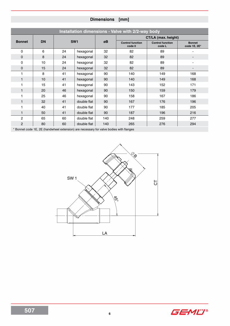
Dimensions [mm]
Installation dimensions - Valve with 2/2-way body
Bonnet DN SW1 øBCT/LA (max. height)
Control function code 0
Control function code L
Bonnet code 1E, 2E*
0 6 24 hexagonal 32 82 89 -0 8 24 hexagonal 32 82 89 -0 10 24 hexagonal 32 82 89 -0 15 24 hexagonal 32 82 89 -1 8 41 hexagonal 90 140 149 1681 10 41 hexagonal 90 140 149 1681 15 41 hexagonal 90 143 152 1711 20 46 hexagonal 90 150 159 1791 25 46 hexagonal 90 158 167 1861 32 41 double flat 90 167 176 1961 40 41 double flat 90 177 185 2051 50 41 double flat 90 187 196 2162 65 60 double flat 140 248 259 2772 80 60 double flat 140 265 276 294
* Bonnet code 1E, 2E (handwheel extension) are necessary for valve bodies with flanges

5077
B
CT SW 1
Dimensions [mm]
Control function code Lwith handwheel clamp
Installation dimensions - Valve with angle body
Bonnet DN SW1 øBCT/LA (max. height)
Control function code 0
Control function code L
1 15 41 hexagonal 90 140 1531 20 46 hexagonal 90 145 1581 25 46 hexagonal 90 154 1671 32 41 double flat 90 159 1721 40 41 double flat 90 170 1831 50 41 double flat 90 181 194
5078
L
d
sLB
45°
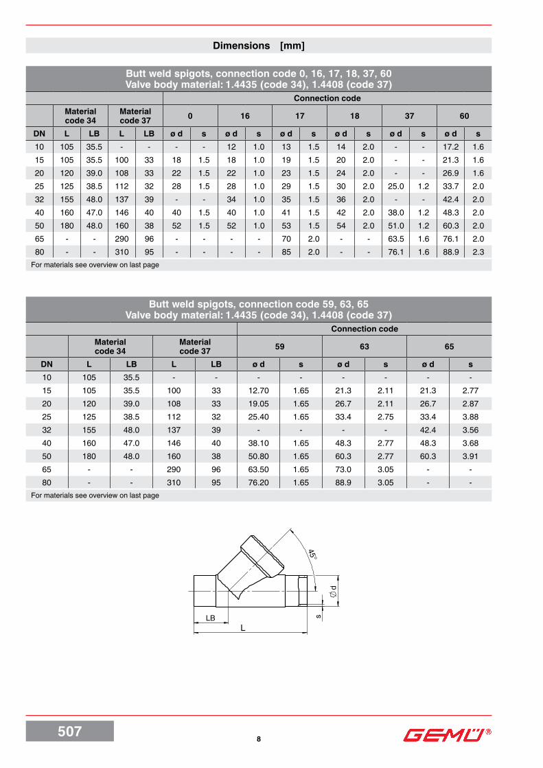
Dimensions [mm]
Butt weld spigots, connection code 0, 16, 17, 18, 37, 60Valve body material: 1.4435 (code 34), 1.4408 (code 37)
Connection codeMaterial code 34
Material code 37 0 16 17 18 37 60
DN L LB L LB ø d s ø d s ø d s ø d s ø d s ø d s10 105 35.5 - - - - 12 1.0 13 1.5 14 2.0 - - 17.2 1.615 105 35.5 100 33 18 1.5 18 1.0 19 1.5 20 2.0 - - 21.3 1.620 120 39.0 108 33 22 1.5 22 1.0 23 1.5 24 2.0 - - 26.9 1.625 125 38.5 112 32 28 1.5 28 1.0 29 1.5 30 2.0 25.0 1.2 33.7 2.032 155 48.0 137 39 - - 34 1.0 35 1.5 36 2.0 - - 42.4 2.040 160 47.0 146 40 40 1.5 40 1.0 41 1.5 42 2.0 38.0 1.2 48.3 2.050 180 48.0 160 38 52 1.5 52 1.0 53 1.5 54 2.0 51.0 1.2 60.3 2.065 - - 290 96 - - - - 70 2.0 - - 63.5 1.6 76.1 2.080 - - 310 95 - - - - 85 2.0 - - 76.1 1.6 88.9 2.3
For materials see overview on last page
Butt weld spigots, connection code 59, 63, 65Valve body material: 1.4435 (code 34), 1.4408 (code 37)
Connection codeMaterial code 34
Material code 37 59 63 65
DN L LB L LB ø d s ø d s ø d s10 105 35.5 - - - - - - - -15 105 35.5 100 33 12.70 1.65 21.3 2.11 21.3 2.7720 120 39.0 108 33 19.05 1.65 26.7 2.11 26.7 2.8725 125 38.5 112 32 25.40 1.65 33.4 2.75 33.4 3.8832 155 48.0 137 39 - - - - 42.4 3.5640 160 47.0 146 40 38.10 1.65 48.3 2.77 48.3 3.6850 180 48.0 160 38 50.80 1.65 60.3 2.77 60.3 3.9165 - - 290 96 63.50 1.65 73.0 3.05 - -80 - - 310 95 76.20 1.65 88.9 3.05 - -
For materials see overview on last page

5079
L
d
sLB
45°
Butt weld spigots, connection code 0, 16, 17, 18, 59, 60 Valve body material: Forged body (code 40)
Connection code0 16 17 18 59 60
DN L LB ø d s ø d s ø d s ø d s ø d s ø d s6* 80 26.5 8 1.0 - - - - - - - - - -8* 80 26.5 10 1.0 - - - - - - - - 13.5 1.6
10* 80 26.5 - - 12 1.0 13 1.5 14 2.0 9.53 0.89 - -15* 80 26.5 - - - - - - - - 12.70 1.65 - -
* only with actuator size 0
Butt weld spigots, connection code 17, 59, 60Valve body material: 1.4435 (code C2)
Connection code17 60 59
DN L LB ø d s ø d s ø d s8 105* 35.5* - - 13.5 1.6 - -
10 105 35.5 13 1.5 17.2 1.6 - -15 105 35.5 19 1.5 21.3 1.6 12.70 1.6520 120 39.0 23 1.5 26.9 1.6 19.05 1.6525 125 39.5 29 1.5 33.7 2.0 25.40 1.6532 155 48.0 35 1.5 42.4 2.0 - -40 160 47.0 41 1.5 48.3 2.0 38.10 1.6550 180 48.0 53 1.5 60.3 2.0 50.80 1.6565 290 96.0 70 2.0 76.1 2.0 63.50 1.6580 310 95.0 85 2.0 88.9 2.3 76.20 1.65
* Connection code 1A: L = 100, LB = 33,5
Dimensions [mm]

50710
45°
R
tL
LB
SW 2
Threaded sockets DIN, connection code 1Valve body material: 1.4408 (code 37)
DN L LB R t SW28* 65 19.0 G 1/4 12.0 17 hexagonal
10* 65 19.0 G 3/8 12.0 24 hexagonal15* 65 19.0 G 1/2 11.4 24 hexagonal10 65 16.5 G 3/8 11.4 27 hexagonal15 65 16.5 G 1/2 15.0 27 hexagonal20 75 17.5 G 3/4 16.3 32 hexagonal25 90 24.0 G 1 19.1 41 hexagonal32 110 33.0 G 1 1/4 21.4 50 octagonal40 120 30.0 G 1 1/2 21.4 55 octagonal50 150 40.0 G 2 25.7 70 octagonal65 190 46.0 G 2 1/2 30.2 85 octagonal80 220 50.0 G 3 33.3 100 octagonal
* only with bonnet size 0
Body dimensions [mm]
Threaded sockets NPT, BS 21 Rc, connection code 3C, 3DValve body material: 1.4408 (code 37)
Connection code3C 3D
DN L LB SW2 R t R t8* 65 19.0 17 hexagonal - - 1/4” NPT 10.1
10* 65 27.0 24 hexagonal - - 3/8” NPT 10.415* 65 27.0 24 hexagonal - - 1/2” NPT 13.615 65 16.5 27 hexagonal Rc 1/2 15.0 1/2” NPT 13.620 75 17.5 32 hexagonal Rc 3/4 16.3 3/4” NPT 14.125 90 24.0 41 hexagonal Rc 1 19.1 1” NPT 17.032 110 33.0 50 octagonal Rc 1 1/4 21.4 1 1/4” NPT 17.540 120 30.0 55 octagonal Rc 1 1/2 21.4 1 1/2” NPT 17.350 150 40.0 70 octagonal Rc 2 25.7 2” NPT 17.865 190 46.0 85 octagonal Rc 2 1/2 30.2 2 1/2” NPT 23.780 220 50.0 100 octagonal Rc 3 33.3 3” NPT 25.8
* only with bonnet size 0

50711
L
45°
R
tLB
R
t
t
R
H2
LE
SW2
Threaded spigots, connection code 9Valve body material: 1.4408 (code 37), Forged body (code 40)
DN L LB t R6* 65 19 12 G 1/48* 65 19 12 G 3/8
10* 65 19 12 G 1/215* 65 19 12 G 3/415 90 25 12 G 3/420 110 30 15 G 125 118 30 15 G 1 1/432 130 38 13 G 1 1/240 140 35 13 G 1 3/450 175 50 15 G 2 3/865 216 52 15 G 380 254 64 18 G 3 1/2
* only with bonnet size 0 For materials see overview on page 13
Body dimensions [mm]
Threaded sockets DIN, connection code 1, 3D / Angle bodyValve body material: 1.4408 (code 37)
Connection code 1 Connection code 3DDN SW2 LE H2 R t R t15 27 30 30.0 G 1/2 15.0 1/2” NPT 13.620 32 35 37.5 G 3/4 16.3 3/4” NPT 14.125 41 41 41.0 G 1 19.1 1” NPT 17.032 50 50 48.0 G 1 1/4 21.4 1 1/4” NPT 17.540 55 50 55.0 G 1 1/2 21.4 1 1/2” NPT 17.350 70 60 62.0 G 2 25.7 2” NPT 17.8

50712
FTF
D
45°
LB
L
k
FTF
D
L
45°
LB
k
Flanges, connection code 10Valve body material: 1.4408 (code 37)
DN FTF LB ø D ø L ø k Number of bolts
15 130 33 95 14 65 420 150 45 105 14 75 425 160 44 115 14 85 432 180 51 140 18 100 440 200 52 150 18 110 450 230 50 165 18 125 4
Body dimensions [mm]
Flanges, connection code 13, 47Valve body material: 1.4435 (code 34)
Connection code 13 Connection code 47
DN FTF LB ø D ø L ø k Number of bolts ø D ø L ø k Number
of bolts15 210 72 95 14 65 4 89.0 15.7 60.5 420 280 78 105 14 75 4 98.6 15.7 69.8 425 280 77 115 14 85 4 108.0 15.7 79.2 432 310 89 140 18 100 4 117.3 15.7 88.9 440 320 91 150 18 110 4 127.0 15.7 98.6 450 330 95 165 18 125 4 152.4 19.1 120.7 4

50713
LBL
45°
d1 d3
Clamp connections, connection code 80, 82, 86, 88Valve body material: 1.4435 (code 34)
DN NPSConnection code Connection code
LB L82 86 88 80
ø d1 ø d3 ø d1 ø d3 ø d1 ø d3 LB L ø d1 ø d315 1/2“ 47.5 130 18.1 50.5 16 34.0 9.40 25.0 33.5 101.6 9.40 25.020 3/4“ 54.0 150 23.7 50.5 20 34.0 15.75 25.0 30.0 101.6 15.75 25.025 1“ 56.0 160 29.7 50.5 26 50.5 22.10 50.5 33.0 114.3 22.10 50.532 1 1/4“ 62.0 180 38.4 64.0 32 50.5 - - - - - -40 1 1/2“ 67.0 200 44.3 64.0 38 50.5 34.80 50.5 37.0 139.7 34.80 50.550 2“ 73.0 230 56.3 77.5 50 64.0 47.50 64.0 36.5 158.8 47.50 64.0
Body dimensions [mm]

For further globe valves, accessories and other products, please see our Product Range catalogue and Price List.Contact GEMÜ.
VALVES, MEASUREMENTAND CONTROL SYSTEMS
GEMÜ Gebr.Müller · Apparatebau GmbH & Co.KG · Fritz-Müller-Str. 6-8 · D-74653 Ingelfingen-Criesbach · Telefon +49(0)7940/123-0 · Telefax +49(0)7940/[email protected] · www.gemu-group.com
Subj
ect t
o al
tera
tion
· 08/
2019
· 88
0544
67Sh
ould
ther
e be
any
dou
bts o
r misu
nder
stan
ding
s, th
e G
erm
anve
rsio
n of
this
data
shee
t is th
e au
thor
itativ
e do
cum
ent!
All r
ight
s in
clud
ing
copy
right
and
indu
stria
l pr
oper
ty ri
ghts
are
exp
ress
ly re
serv
ed.
Overview of metal bodies for GEMÜ 507Threaded connections Clamps Flanges
Connection code 1 3C 9 3D 80 82 86 88 10** 13 47
Material code 37 37 37 37 40 37 37 34 34 34 34 37 34 34
Body configuration
2/2-way body
Angle body
2/2-way body
Angle body
DN 6 - - - - X* - - - - - - - - -DN 8 X* - - X* - X* - - - - - - - -
DN 10 X* - - X* - X* - - - - - - - -DN 15 X* - - X* - X* - - - - - - - -DN 10 X - - - - - - - - - - - - -DN 15 X X X X - X X X X X X X X XDN 20 X X X X - X X X X X X X X XDN 25 X X X X - X X X X X X X X XDN 32 X X X X - X X - X X - X X XDN 40 X X X X - X X X X X X X X XDN 50 X X X X - X X X X X X X X XDN 65 X - X X - X - - - - - - - -DN 80 X - X X - X - - - - - - - -
* only with bonnet size 0 ** only with bonnet size 1E or 2E
Overview of metal bodies for GEMÜ 507Spigots
Connection code 0 16 17 18 37 59 60 63 65
Material code 34 40 34 40 34 37 40 C2 34 40 34 37 34 37 40 C2 34 37 40 C2 37 34
DN 6 - X* - - - - - - - - - - - - - - - - - - - -DN 8 - X* - - - - - - - - - - - - - - - - X* - - -
DN 10 - - - X* - - X* - - X* - - - - X* - - - - - - -DN 15 - - - - - - - - - - - - - - X* - - - - - - -DN 8 - - - - - - - - - - - - - - - - - - - X - -
DN 10 - - X - X - - X - - - - - - - - X - - X - -DN 15 X - X - X X - X X - - - X - - X X X - X X XDN 20 X - X - X X - X X - - - X - - X X X - X X XDN 25 X - X - X X - X X - X - X - - X X X - X X XDN 32 - - X - X X - X X - - - - - - - X X - X - XDN 40 X - X - X X - X X - X - X - - X X X - X X XDN 50 X - X - X X - X X - X - X - - X X X - X X XDN 65 - - - - - X - X - - - X - X - X - X - X X -DN 80 - - - - - X - X - - - X - X - X - X - X X -
* only with bonnet size 0