SECTION ROAD WHEELS & TIRES
36
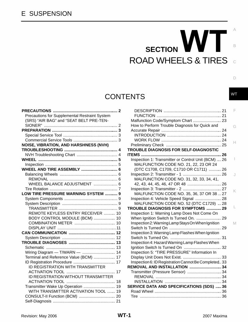
WT-1 ROAD WHEELS & TIRES E SUSPENSION CONTENTS C D F G H I J K L M SECTION A B WT Revision: May 2006 2007 Maxima PRECAUTIONS ......................................................... 2 Precautions for Supplemental Restraint System (SRS) “AIR BAG” and “SEAT BELT PRE-TEN- SIONER” ................................................................. 2 PREPARATION .......................................................... 3 Special Service Tool ................................................ 3 Commercial Service Tools ....................................... 3 NOISE, VIBRATION, AND HARSHNESS (NVH) TROUBLESHOOTING ............................................... 4 NVH Troubleshooting Chart .................................... 4 WHEEL ...................................................................... 5 Inspection ................................................................ 5 WHEEL AND TIRE ASSEMBLY ................................ 6 Balancing Wheels ................................................... 6 REMOVAL ............................................................ 6 WHEEL BALANCE ADJUSTMENT ..................... 6 Tire Rotation ............................................................ 7 LOW TIRE PRESSURE WARNING SYSTEM ........... 9 System Components ............................................... 9 System Description ................................................. 9 TRANSMITTER .................................................... 9 REMOTE KEYLESS ENTRY RECEIVER .......... 10 BODY CONTROL MODULE (BCM) ................... 10 COMBINATION METER .................................... 10 DISPLAY UNIT .................................................... 11 CAN COMMUNICATION ......................................... 12 System Description ............................................... 12 TROUBLE DIAGNOSES ......................................... 13 Schematic ............................................................. 13 Wiring Diagram — T/WARN — ............................. 14 Terminal and Reference Value (BCM) ................... 17 ID Registration Procedure ..................................... 17 ID REGISTRATION WITH TRANSMITTER ACTIVATION TOOL ........................................... 17 ID REGISTRATION WITHOUT TRANSMITTER ACTIVATION TOOL ........................................... 18 Transmitter Wake Up Operation ............................ 19 WITH TRANSMITTER ACTIVATION TOOL ....... 19 CONSULT-II Function (BCM) ................................ 20 Self-Diagnosis ....................................................... 21 DESCRIPTION ................................................... 21 FUNCTION ......................................................... 21 Malfunction Code/Symptom Chart ......................... 23 How to Perform Trouble Diagnosis for Quick and Accurate Repair ..................................................... 24 INTRODUCTION ................................................ 24 WORK FLOW ..................................................... 24 Preliminary Check ................................................. 25 TROUBLE DIAGNOSIS FOR SELF-DIAGNOSTIC ITEMS ....................................................................... 26 Inspection 1: Transmitter or Control Unit (BCM) .... 26 MALFUNCTION CODE NO. 21, 22, 23 OR 24 (DTC C1708, C1709, C1710 OR C1711) ........... 26 Inspection 2: Transmitter - 1 .................................. 26 MALFUNCTION CODE NO. 31, 32, 33, 34, 41, 42, 43, 44, 45, 46, 47 OR 48 .............................. 26 Inspection 3: Transmitter - 2 .................................. 27 MALFUNCTION CODE NO. 35, 36, 37 OR 38 ... 27 Inspection 4: Vehicle Speed Signal ....................... 28 MALFUNCTION CODE NO. 52 (DTC C1729) ... 28 TROUBLE DIAGNOSIS FOR SYMPTOMS ............. 29 Inspection 1: Warning Lamp Does Not Come On When Ignition Switch Is Turned On. ...................... 29 Inspection 2: Warning Lamp Stays On When Ignition Switch Is Turned On .............................................. 29 Inspection 3: Warning Lamp Flashes When Ignition Switch Is Turned On. ............................................. 31 Inspection 4: Hazard Warning Lamp Flashes When Ignition Switch Is Turned On ................................. 32 Inspection 5: “TIRE PRESSURE” Information In Display Unit Does Not Exist. .................................. 33 Inspection 6: ID Registration Cannot Be Completed ... 33 REMOVAL AND INSTALLATION ............................ 34 Transmitter (Pressure Sensor) .............................. 34 REMOVAL .......................................................... 34 INSTALLATION .................................................. 34 SERVICE DATA AND SPECIFICATIONS (SDS) ..... 36 Road Wheel ........................................................... 36 Tire ........................................................................ 36
Transcript of SECTION ROAD WHEELS & TIRES
WT-1
ROAD WHEELS & TIRES
E SUSPENSION
CONTENTS
C
D
F
G
H
I
J
K
L
M
SECTION
A
B
WT
Revision: May 2006 2007 Maxima
PRECAUTIONS .......................................................... 2Precautions for Supplemental Restraint System (SRS) “AIR BAG” and “SEAT BELT PRE-TEN-SIONER” .................................................................. 2
PREPARATION ........................................................... 3Special Service Tool ................................................. 3Commercial Service Tools ........................................ 3
NOISE, VIBRATION, AND HARSHNESS (NVH) TROUBLESHOOTING ................................................ 4
NVH Troubleshooting Chart ..................................... 4WHEEL ....................................................................... 5
Inspection ................................................................. 5WHEEL AND TIRE ASSEMBLY ................................. 6
Balancing Wheels .................................................... 6REMOVAL ............................................................. 6WHEEL BALANCE ADJUSTMENT ...................... 6
Tire Rotation ............................................................. 7LOW TIRE PRESSURE WARNING SYSTEM ............ 9
System Components ................................................ 9System Description .................................................. 9
TRANSMITTER ..................................................... 9REMOTE KEYLESS ENTRY RECEIVER ........... 10BODY CONTROL MODULE (BCM) .................... 10COMBINATION METER ..................................... 10DISPLAY UNIT .....................................................11
CAN COMMUNICATION .......................................... 12System Description ................................................ 12
TROUBLE DIAGNOSES .......................................... 13Schematic .............................................................. 13Wiring Diagram — T/WARN — .............................. 14Terminal and Reference Value (BCM) .................... 17ID Registration Procedure ...................................... 17
ID REGISTRATION WITH TRANSMITTER ACTIVATION TOOL ............................................ 17ID REGISTRATION WITHOUT TRANSMITTER ACTIVATION TOOL ............................................ 18
Transmitter Wake Up Operation ............................. 19WITH TRANSMITTER ACTIVATION TOOL ........ 19
CONSULT-II Function (BCM) ................................. 20Self-Diagnosis ........................................................ 21
DESCRIPTION .................................................... 21FUNCTION .......................................................... 21
Malfunction Code/Symptom Chart .......................... 23How to Perform Trouble Diagnosis for Quick and Accurate Repair ...................................................... 24
INTRODUCTION ................................................. 24WORK FLOW ...................................................... 24
Preliminary Check .................................................. 25TROUBLE DIAGNOSIS FOR SELF-DIAGNOSTIC ITEMS ........................................................................ 26
Inspection 1: Transmitter or Control Unit (BCM) ..... 26MALFUNCTION CODE NO. 21, 22, 23 OR 24 (DTC C1708, C1709, C1710 OR C1711) ............ 26
Inspection 2: Transmitter - 1 ................................... 26MALFUNCTION CODE NO. 31, 32, 33, 34, 41, 42, 43, 44, 45, 46, 47 OR 48 ............................... 26
Inspection 3: Transmitter - 2 ................................... 27MALFUNCTION CODE NO. 35, 36, 37 OR 38 ... 27
Inspection 4: Vehicle Speed Signal ........................ 28MALFUNCTION CODE NO. 52 (DTC C1729) .... 28
TROUBLE DIAGNOSIS FOR SYMPTOMS .............. 29Inspection 1: Warning Lamp Does Not Come On When Ignition Switch Is Turned On. ....................... 29Inspection 2: Warning Lamp Stays On When Ignition Switch Is Turned On ............................................... 29Inspection 3: Warning Lamp Flashes When Ignition Switch Is Turned On. .............................................. 31Inspection 4: Hazard Warning Lamp Flashes When Ignition Switch Is Turned On .................................. 32Inspection 5: “TIRE PRESSURE” Information In Display Unit Does Not Exist. ................................... 33Inspection 6: ID Registration Cannot Be Completed ... 33
REMOVAL AND INSTALLATION ............................. 34Transmitter (Pressure Sensor) ............................... 34
REMOVAL ........................................................... 34INSTALLATION ................................................... 34
SERVICE DATA AND SPECIFICATIONS (SDS) ...... 36Road Wheel ............................................................ 36Tire ......................................................................... 36
WT-2
PRECAUTIONS
Revision: May 2006 2007 Maxima
PRECAUTIONS PFP:00001
Precautions for Supplemental Restraint System (SRS) “AIR BAG” and “SEAT BELT PRE-TENSIONER” EES002E4
The Supplemental Restraint System such as “AIR BAG” and “SEAT BELT PRE-TENSIONER”, used alongwith a front seat belt, helps to reduce the risk or severity of injury to the driver and front passenger for certaintypes of collision. This system includes seat belt switch inputs and dual stage front air bag modules. The SRSsystem uses the seat belt switches to determine the front air bag deployment, and may only deploy one frontair bag, depending on the severity of a collision and whether the front occupants are belted or unbelted.Information necessary to service the system safely is included in the SRS and SB section of this Service Man-ual.WARNING:� To avoid rendering the SRS inoperative, which could increase the risk of personal injury or death
in the event of a collision which would result in air bag inflation, all maintenance must be per-formed by an authorized NISSAN/INFINITI dealer.
� Improper maintenance, including incorrect removal and installation of the SRS, can lead to per-sonal injury caused by unintentional activation of the system. For removal of Spiral Cable and AirBag Module, see the SRS section.
� Do not use electrical test equipment on any circuit related to the SRS unless instructed to in thisService Manual. SRS wiring harnesses can be identified by yellow and/or orange harnesses orharness connectors.
PREPARATION
WT-3
C
D
F
G
H
I
J
K
L
M
A
B
WT
Revision: May 2006 2007 Maxima
PREPARATION PFP:00002
Special Service Tool EES002DC
The actual shapes of Kent-Moore tools may differ from those of special service tools illustrated here.
Commercial Service Tools EES002DD
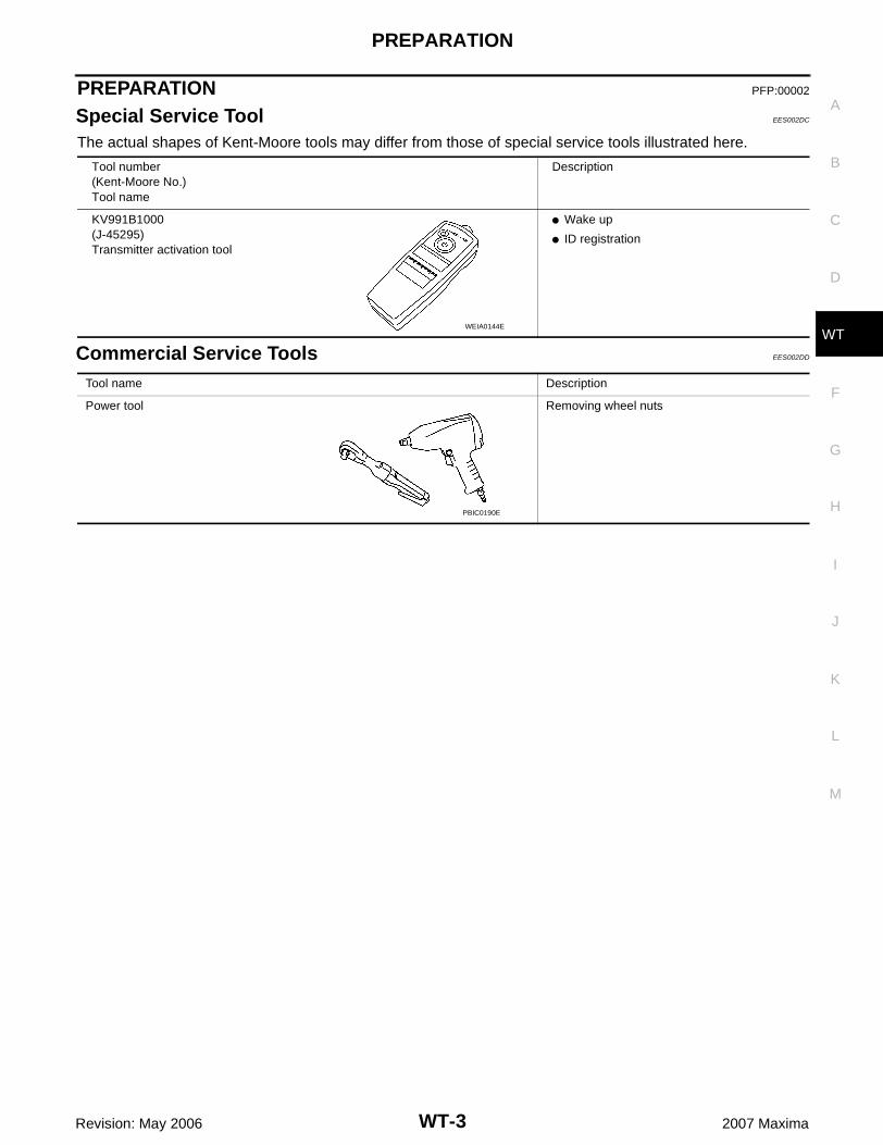
Tool number (Kent-Moore No.)Tool name
Description
KV991B1000(J-45295)Transmitter activation tool
� Wake up
� ID registration
WEIA0144E
Tool name Description
Power tool Removing wheel nuts
PBIC0190E
WT-4
NOISE, VIBRATION, AND HARSHNESS (NVH) TROUBLESHOOTING
Revision: May 2006 2007 Maxima
NOISE, VIBRATION, AND HARSHNESS (NVH) TROUBLESHOOTING PFP:00003
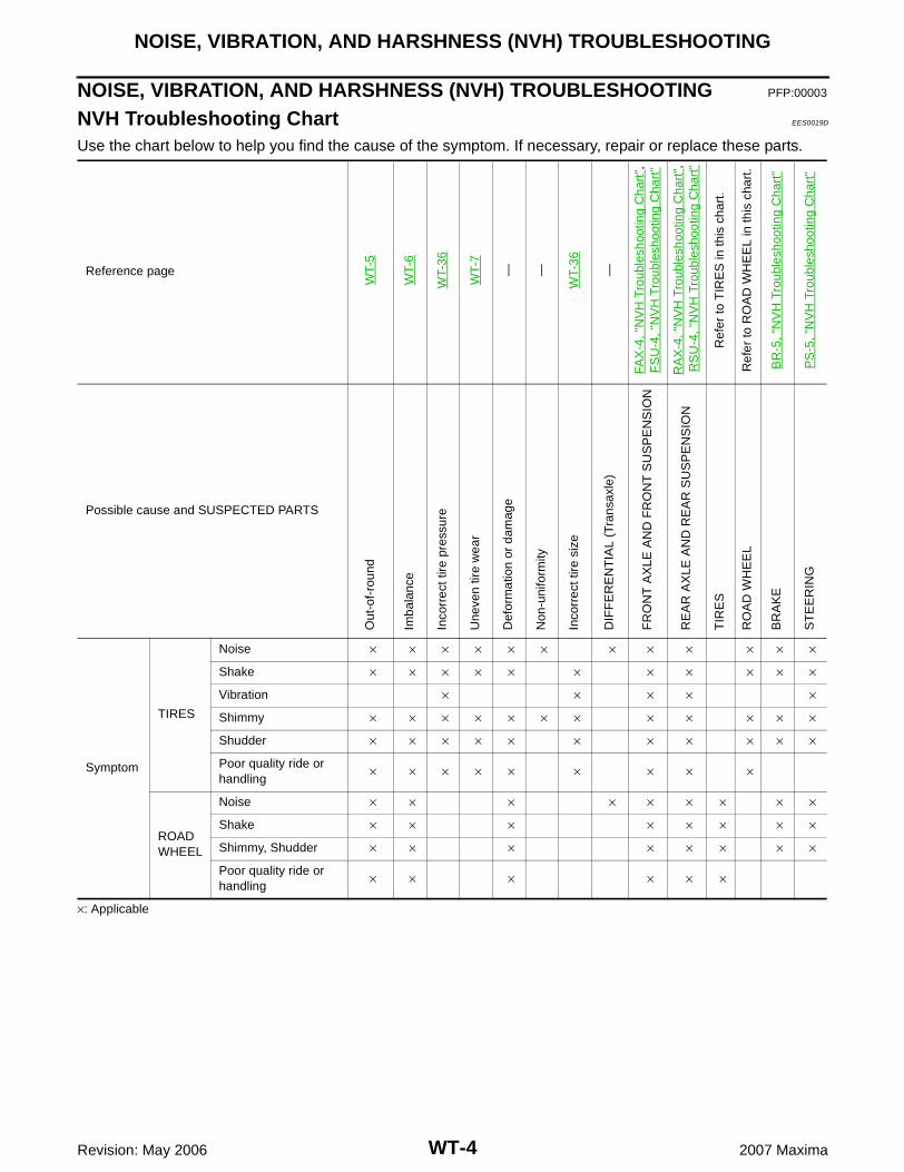
NVH Troubleshooting Chart EES0019D
Use the chart below to help you find the cause of the symptom. If necessary, repair or replace these parts.
×: Applicable
Reference page
WT-
5
WT-
6
WT-
36
WT-
7
— —
WT-
36
—
FAX
-4, "
NV
H T
roub
lesh
ootin
g C
hart
",F
SU
-4, "
NV
H T
roub
lesh
ootin
g C
hart
"
RA
X-4
, "N
VH
Tro
uble
shoo
ting
Cha
rt",
RS
U-4
, "N
VH
Tro
uble
shoo
ting
Cha
rt"
Ref
er to
TIR
ES
in th
is c
hart
.
Ref
er to
RO
AD
WH
EE
L in
this
cha
rt.
BR
-5, "
NV
H T
roub
lesh
ootin
g C
hart
"
PS
-5, "
NV
H T
roub
lesh
ootin
g C
hart
"
Possible cause and SUSPECTED PARTS
Out
-of-
roun
d
Imba
lanc
e
Inco
rrec
t tire
pre
ssur
e
Une
ven
tire
wea
r
Def
orm
atio
n or
dam
age
Non
-uni
form
ity
Inco
rrec
t tire
siz
e
DIF
FE
RE
NT
IAL
(Tra
nsax
le)
FR
ON
T A
XLE
AN
D F
RO
NT
SU
SP
EN
SIO
N
RE
AR
AX
LE A
ND
RE
AR
SU
SP
EN
SIO
N
TIR
ES
RO
AD
WH
EE
L
BR
AK
E
ST
EE
RIN
G
Symptom
TIRES
Noise × × × × × × × × × × × ×
Shake × × × × × × × × × × ×
Vibration × × × × ×
Shimmy × × × × × × × × × × × ×
Shudder × × × × × × × × × × ×
Poor quality ride or handling
× × × × × × × × ×
ROAD WHEEL
Noise × × × × × × × × ×
Shake × × × × × × × ×
Shimmy, Shudder × × × × × × × ×
Poor quality ride or handling
× × × × × ×
WHEEL
WT-5
C
D
F
G
H
I
J
K
L
M
A
B
WT
Revision: May 2006 2007 Maxima
WHEEL PFP:40300
Inspection EES0019E
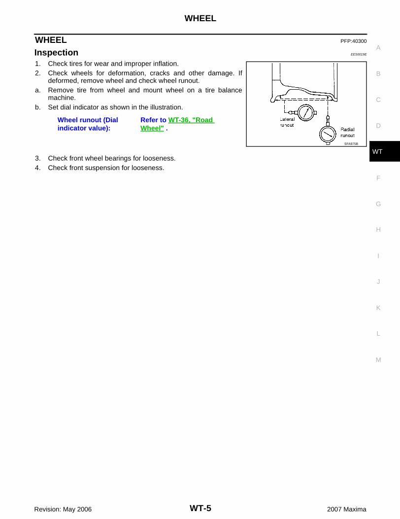
1. Check tires for wear and improper inflation.2. Check wheels for deformation, cracks and other damage. If
deformed, remove wheel and check wheel runout.a. Remove tire from wheel and mount wheel on a tire balance
machine.b. Set dial indicator as shown in the illustration.
3. Check front wheel bearings for looseness.4. Check front suspension for looseness.
Wheel runout (Dial indicator value):
Refer to WT-36, "Road Wheel" .
SFA975B
WT-6
WHEEL AND TIRE ASSEMBLY
Revision: May 2006 2007 Maxima
WHEEL AND TIRE ASSEMBLY PFP:40300
Balancing Wheels EES0019F
REMOVAL1. Remove inner and outer balance weights from the wheel.
CAUTION:Be careful not to scratch the wheel during removal procedures.
2. Using releasing agent, remove double-faced adhesive tape from the wheel.CAUTION:� Be careful not to scratch the wheel during removal.� After removing double-faced adhesive tape, wipe clean traces of releasing agent from the
wheel.
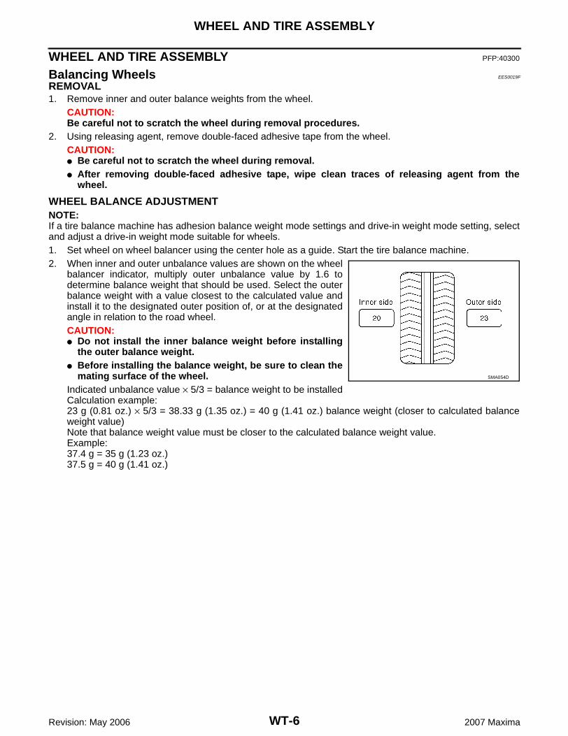
WHEEL BALANCE ADJUSTMENTNOTE:If a tire balance machine has adhesion balance weight mode settings and drive-in weight mode setting, selectand adjust a drive-in weight mode suitable for wheels.1. Set wheel on wheel balancer using the center hole as a guide. Start the tire balance machine.2. When inner and outer unbalance values are shown on the wheel
balancer indicator, multiply outer unbalance value by 1.6 todetermine balance weight that should be used. Select the outerbalance weight with a value closest to the calculated value andinstall it to the designated outer position of, or at the designatedangle in relation to the road wheel.CAUTION:� Do not install the inner balance weight before installing
the outer balance weight.� Before installing the balance weight, be sure to clean the
mating surface of the wheel.Indicated unbalance value × 5/3 = balance weight to be installedCalculation example:23 g (0.81 oz.) × 5/3 = 38.33 g (1.35 oz.) = 40 g (1.41 oz.) balance weight (closer to calculated balanceweight value)Note that balance weight value must be closer to the calculated balance weight value.Example:37.4 g = 35 g (1.23 oz.)37.5 g = 40 g (1.41 oz.)
SMA054D
WHEEL AND TIRE ASSEMBLY
WT-7
C
D
F
G
H
I
J
K
L
M
A
B
WT
Revision: May 2006 2007 Maxima
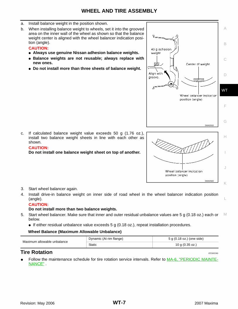
a. Install balance weight in the position shown.b. When installing balance weight to wheels, set it into the grooved
area on the inner wall of the wheel as shown so that the balanceweight center is aligned with the wheel balancer indication posi-tion (angle).CAUTION:� Always use genuine Nissan adhesion balance weights.� Balance weights are not reusable; always replace with
new ones.� Do not install more than three sheets of balance weight.
c. If calculated balance weight value exceeds 50 g (1.76 oz.),install two balance weight sheets in line with each other asshown.CAUTION:Do not install one balance weight sheet on top of another.
3. Start wheel balancer again.4. Install drive-in balance weight on inner side of road wheel in the wheel balancer indication position
(angle).CAUTION:Do not install more than two balance weights.
5. Start wheel balancer. Make sure that inner and outer residual unbalance values are 5 g (0.18 oz.) each orbelow.� If either residual unbalance value exceeds 5 g (0.18 oz.), repeat installation procedures.
Wheel Balance (Maximum Allowable Unbalance)
Tire Rotation EES0019G
� Follow the maintenance schedule for tire rotation service intervals. Refer to MA-6, "PERIODIC MAINTE-NANCE" .
SMA055D
SMA056D
Maximum allowable unbalanceDynamic (At rim flange) 5 g (0.18 oz.) (one side)
Static 10 g (0.35 oz.)

WT-8
WHEEL AND TIRE ASSEMBLY
Revision: May 2006 2007 Maxima
� Do not include the T-type spare tire when rotating the tires asshown.
� Tighten wheel nuts to specification.CAUTION:When installing wheels, tighten them diagonally by dividingthe work two to three times in order to prevent the wheelsfrom developing any distortion.
� After rotating the tires, adjust the tire pressure.
Wheel nut : 108 N·m (11 kg-m, 80 ft-lb)
WEIA0044E

LOW TIRE PRESSURE WARNING SYSTEM
WT-9
C
D
F
G
H
I
J
K
L
M
A
B
WT
Revision: May 2006 2007 Maxima
LOW TIRE PRESSURE WARNING SYSTEM PFP:40300
System Components EES002E5
System Description EES002E6
TRANSMITTERA sensor-transmitter integrated with a valve is installed in eachwheel, and transmits a detected air pressure signal in the form of aradio wave.
WEIA0174E
1. Remote keyless entry receiverM120
2. Display control unit, M94, M95Unified meter and A/C AMP.M49, M50
3. Transmitters
4. Tire pressure warning check connectorM123
5. BCMM18, M20
6. Combination meterM24
7. Display unitM93
WEIA0137E
WT-10
LOW TIRE PRESSURE WARNING SYSTEM
Revision: May 2006 2007 Maxima
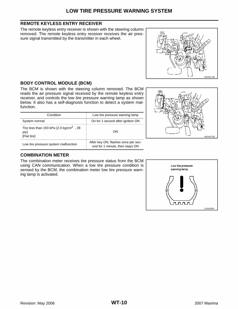
REMOTE KEYLESS ENTRY RECEIVERThe remote keyless entry receiver is shown with the steering columnremoved. The remote keyless entry receiver receives the air pres-sure signal transmitted by the transmitter in each wheel.
BODY CONTROL MODULE (BCM)The BCM is shown with the steering column removed. The BCMreads the air pressure signal received by the remote keyless entryreceiver, and controls the low tire pressure warning lamp as shownbelow. It also has a self-diagnosis function to detect a system mal-function.
COMBINATION METERThe combination meter receives tire pressure status from the BCMusing CAN communication. When a low tire pressure condition issensed by the BCM, the combination meter low tire pressure warn-ing lamp is activated.
WEIA0175E
Condition Low tire pressure warning lamp
System normal On for 1 second after ignition ON
Tire less than 193 kPa (2.0 kg/cm2 , 28 psi)[Flat tire]
ON
Low tire pressure system malfunctionAfter key ON, flashes once per sec-
ond for 1 minute, then stays ON
WEIA0176E
LEIA0055E
LOW TIRE PRESSURE WARNING SYSTEM
WT-11
C
D
F
G
H
I
J
K
L
M
A
B
WT
Revision: May 2006 2007 Maxima
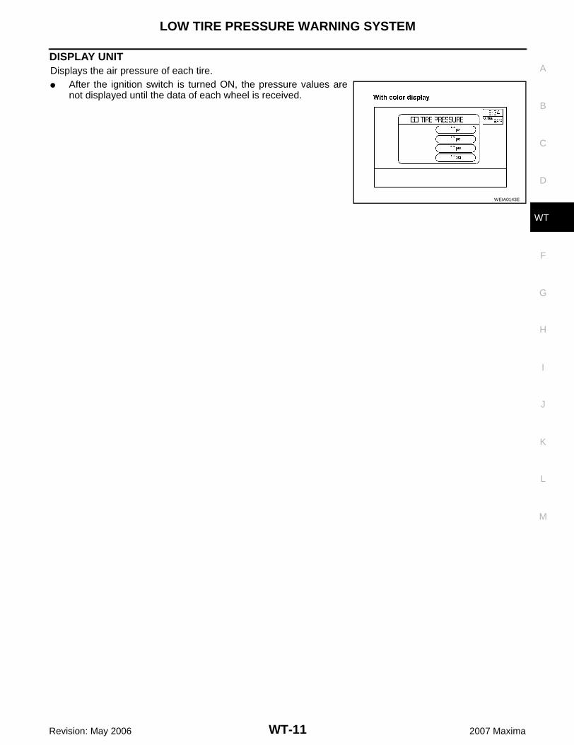
DISPLAY UNITDisplays the air pressure of each tire.� After the ignition switch is turned ON, the pressure values are
not displayed until the data of each wheel is received.
WEIA0143E
WT-12
CAN COMMUNICATION
Revision: May 2006 2007 Maxima
CAN COMMUNICATION PFP:23710
System Description EES002DI
Refer to LAN-4, "SYSTEM DESCRIPTION" .
TROUBLE DIAGNOSES
WT-13
C
D
F
G
H
I
J
K
L
M
A
B
WT
Revision: May 2006 2007 Maxima
TROUBLE DIAGNOSES PFP:00004
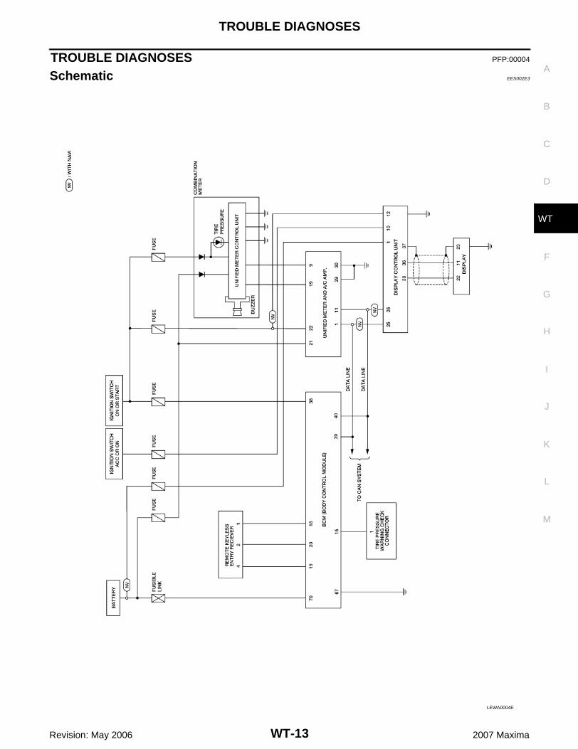
Schematic EES002E3
LEWA0004E
WT-14
TROUBLE DIAGNOSES
Revision: May 2006 2007 Maxima
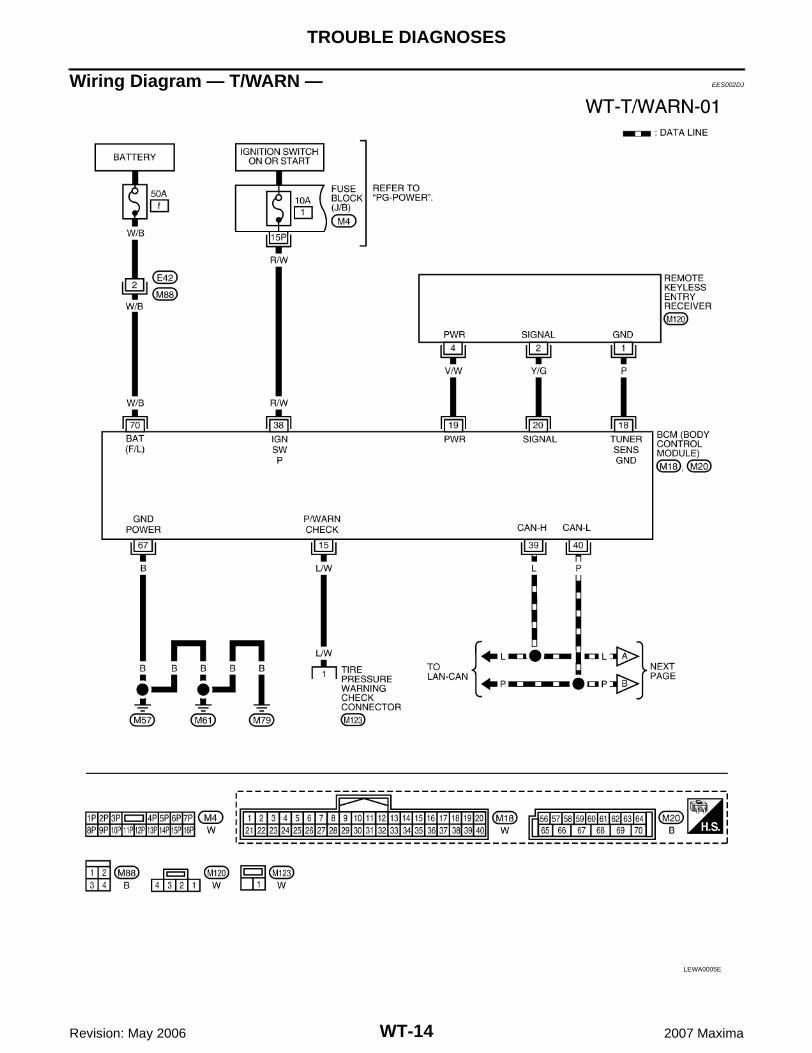
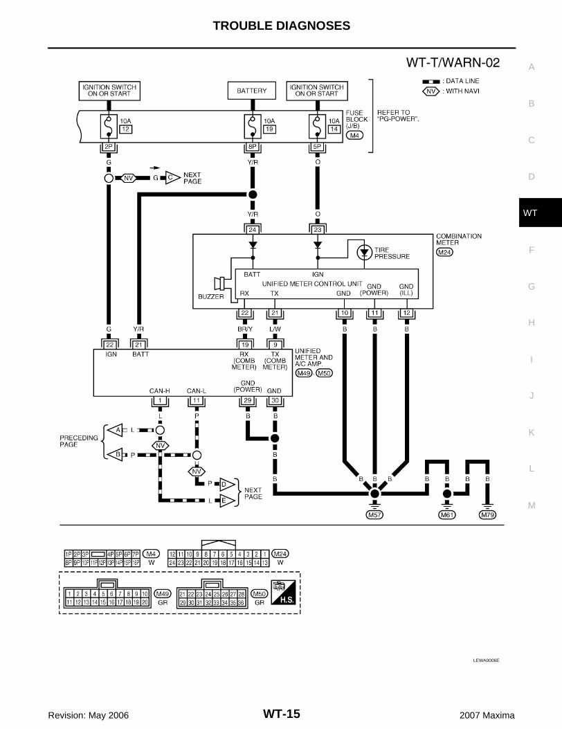
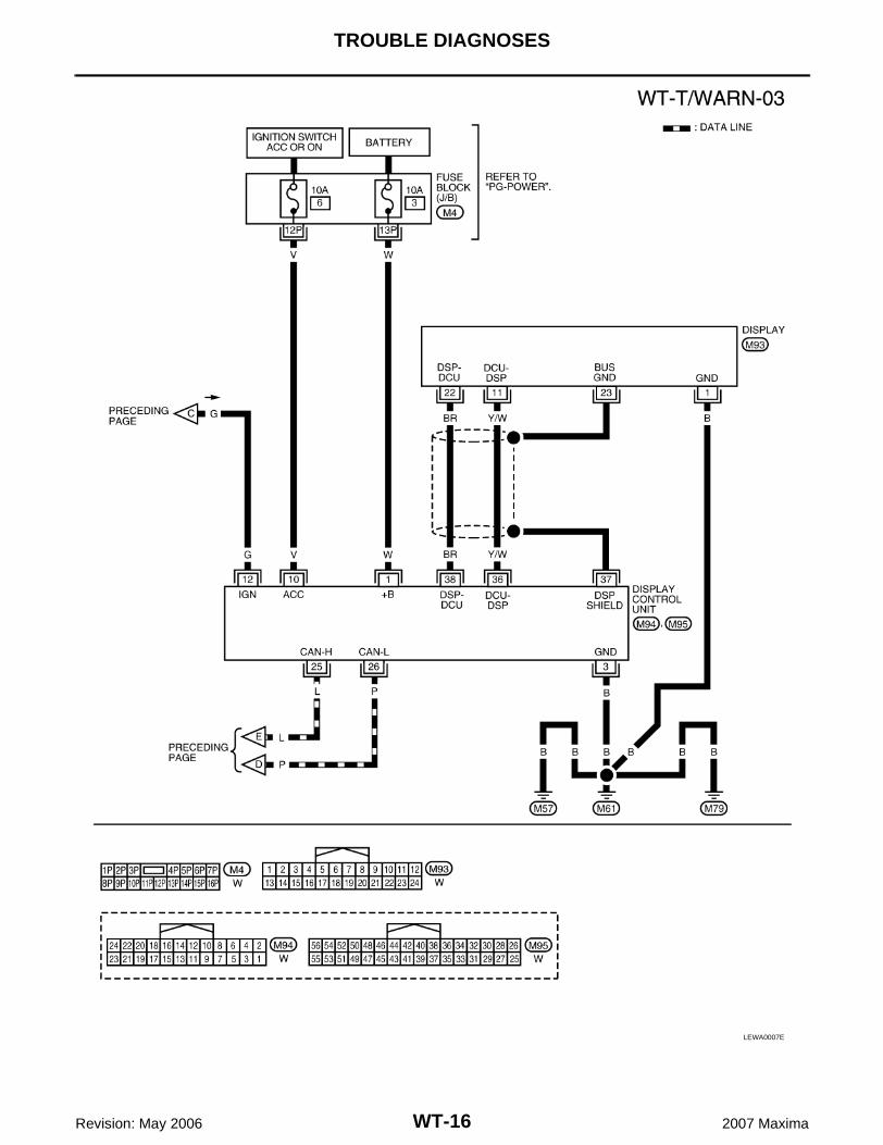
Wiring Diagram — T/WARN — EES002DJ
LEWA0005E
TROUBLE DIAGNOSES
WT-15
C
D
F
G
H
I
J
K
L
M
A
B
WT
Revision: May 2006 2007 Maxima
LEWA0006E
WT-16
TROUBLE DIAGNOSES
Revision: May 2006 2007 Maxima
LEWA0007E
TROUBLE DIAGNOSES
WT-17
C
D
F
G
H
I
J
K
L
M
A
B
WT
Revision: May 2006 2007 Maxima
Terminal and Reference Value (BCM) EES002DK
Refer to BCS-12, "Terminals and Reference Values for BCM" .
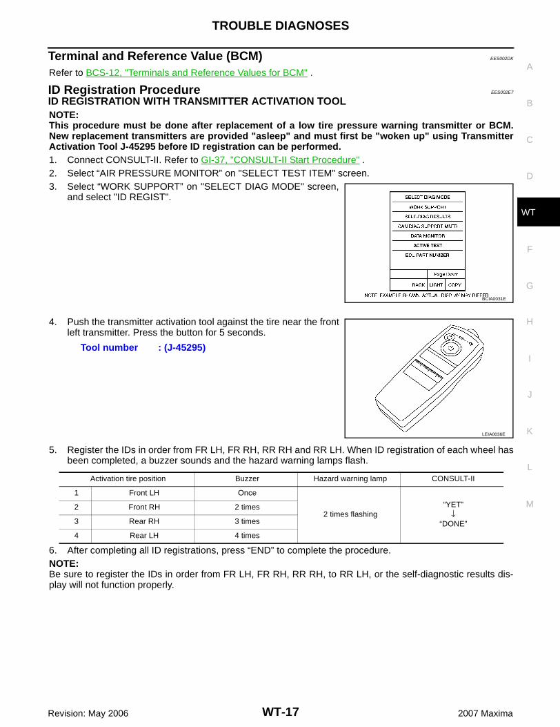
ID Registration Procedure EES002E7
ID REGISTRATION WITH TRANSMITTER ACTIVATION TOOLNOTE:This procedure must be done after replacement of a low tire pressure warning transmitter or BCM.New replacement transmitters are provided "asleep" and must first be "woken up" using TransmitterActivation Tool J-45295 before ID registration can be performed.1. Connect CONSULT-II. Refer to GI-37, "CONSULT-II Start Procedure" .2. Select “AIR PRESSURE MONITOR” on "SELECT TEST ITEM" screen.3. Select “WORK SUPPORT” on "SELECT DIAG MODE" screen,
and select "ID REGIST".
4. Push the transmitter activation tool against the tire near the frontleft transmitter. Press the button for 5 seconds.
5. Register the IDs in order from FR LH, FR RH, RR RH and RR LH. When ID registration of each wheel hasbeen completed, a buzzer sounds and the hazard warning lamps flash.
6. After completing all ID registrations, press “END” to complete the procedure.NOTE:Be sure to register the IDs in order from FR LH, FR RH, RR RH, to RR LH, or the self-diagnostic results dis-play will not function properly.
BCIA0031E
Tool number : (J-45295)
LEIA0036E
Activation tire position Buzzer Hazard warning lamp CONSULT-II
1 Front LH Once
2 times flashing“YET”
↓“DONE”
2 Front RH 2 times
3 Rear RH 3 times
4 Rear LH 4 times
WT-18
TROUBLE DIAGNOSES
Revision: May 2006 2007 Maxima
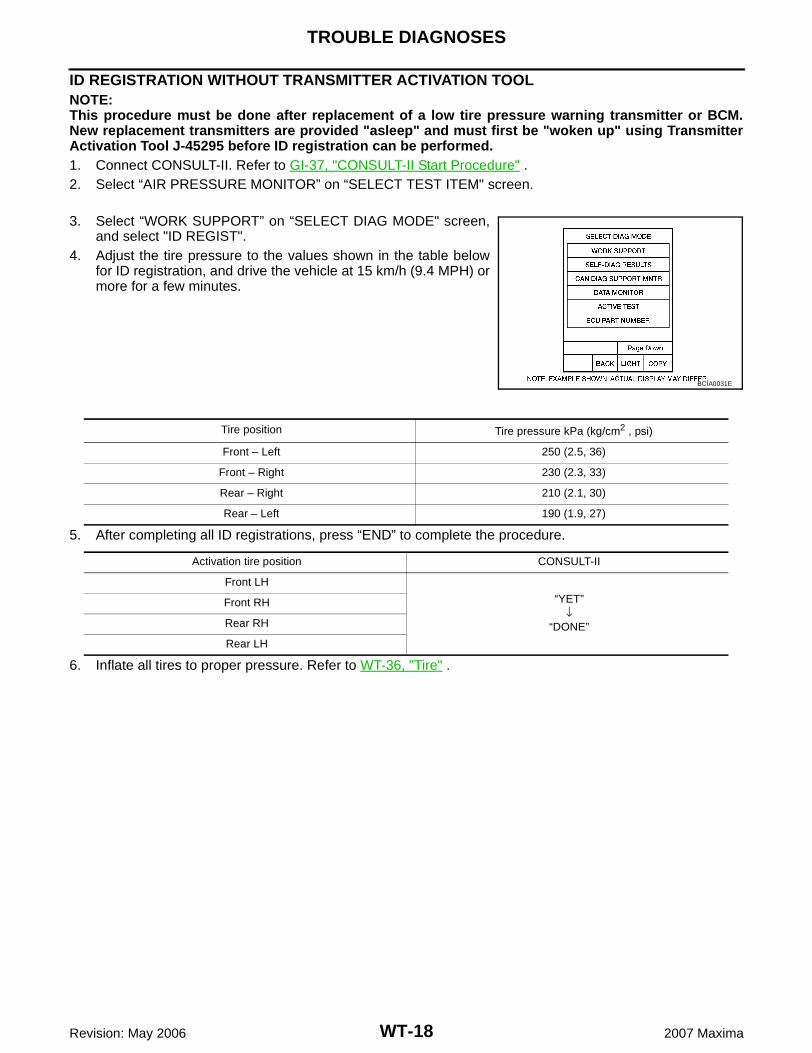
ID REGISTRATION WITHOUT TRANSMITTER ACTIVATION TOOLNOTE:This procedure must be done after replacement of a low tire pressure warning transmitter or BCM.New replacement transmitters are provided "asleep" and must first be "woken up" using TransmitterActivation Tool J-45295 before ID registration can be performed.1. Connect CONSULT-II. Refer to GI-37, "CONSULT-II Start Procedure" .2. Select “AIR PRESSURE MONITOR” on “SELECT TEST ITEM" screen.
3. Select “WORK SUPPORT” on “SELECT DIAG MODE" screen,and select "ID REGIST".
4. Adjust the tire pressure to the values shown in the table belowfor ID registration, and drive the vehicle at 15 km/h (9.4 MPH) ormore for a few minutes.
5. After completing all ID registrations, press “END” to complete the procedure.
6. Inflate all tires to proper pressure. Refer to WT-36, "Tire" .
BCIA0031E
Tire position Tire pressure kPa (kg/cm2 , psi)
Front – Left 250 (2.5, 36)
Front – Right 230 (2.3, 33)
Rear – Right 210 (2.1, 30)
Rear – Left 190 (1.9, 27)
Activation tire position CONSULT-II
Front LH
“YET”↓
“DONE”
Front RH
Rear RH
Rear LH
TROUBLE DIAGNOSES
WT-19
C
D
F
G
H
I
J
K
L
M
A
B
WT
Revision: May 2006 2007 Maxima
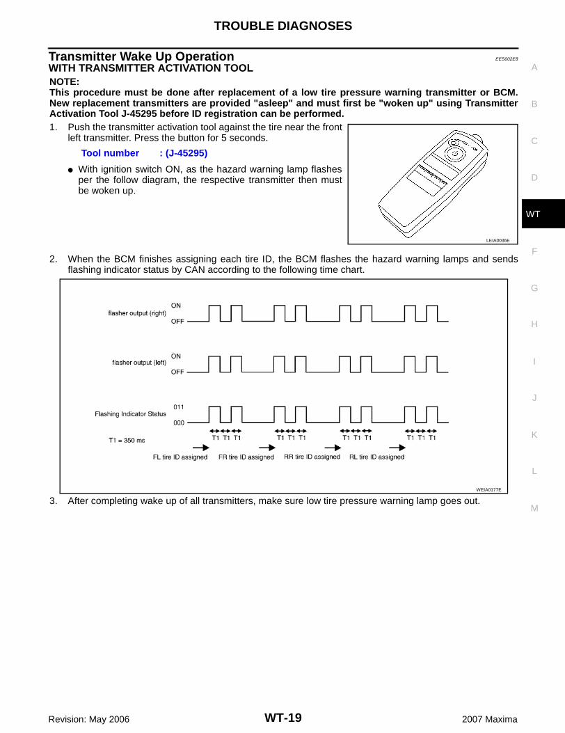
Transmitter Wake Up Operation EES002E8
WITH TRANSMITTER ACTIVATION TOOLNOTE:This procedure must be done after replacement of a low tire pressure warning transmitter or BCM.New replacement transmitters are provided "asleep" and must first be "woken up" using TransmitterActivation Tool J-45295 before ID registration can be performed.1. Push the transmitter activation tool against the tire near the front
left transmitter. Press the button for 5 seconds.
� With ignition switch ON, as the hazard warning lamp flashesper the follow diagram, the respective transmitter then mustbe woken up.
2. When the BCM finishes assigning each tire ID, the BCM flashes the hazard warning lamps and sendsflashing indicator status by CAN according to the following time chart.
3. After completing wake up of all transmitters, make sure low tire pressure warning lamp goes out.
Tool number : (J-45295)
LEIA0036E
WEIA0177E
WT-20
TROUBLE DIAGNOSES
Revision: May 2006 2007 Maxima
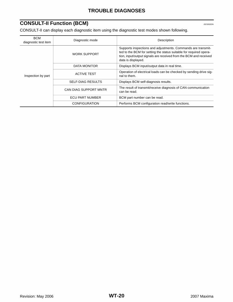
CONSULT-II Function (BCM) EES002DN
CONSULT-II can display each diagnostic item using the diagnostic test modes shown following.
BCMdiagnostic test item
Diagnostic mode Description
Inspection by part
WORK SUPPORT
Supports inspections and adjustments. Commands are transmit-ted to the BCM for setting the status suitable for required opera-tion, input/output signals are received from the BCM and received data is displayed.
DATA MONITOR Displays BCM input/output data in real time.
ACTIVE TESTOperation of electrical loads can be checked by sending drive sig-nal to them.
SELF-DIAG RESULTS Displays BCM self-diagnosis results.
CAN DIAG SUPPORT MNTRThe result of transmit/receive diagnosis of CAN communication can be read.
ECU PART NUMBER BCM part number can be read.
CONFIGURATION Performs BCM configuration read/write functions.
TROUBLE DIAGNOSES
WT-21
C
D
F
G
H
I
J
K
L
M
A
B
WT
Revision: May 2006 2007 Maxima
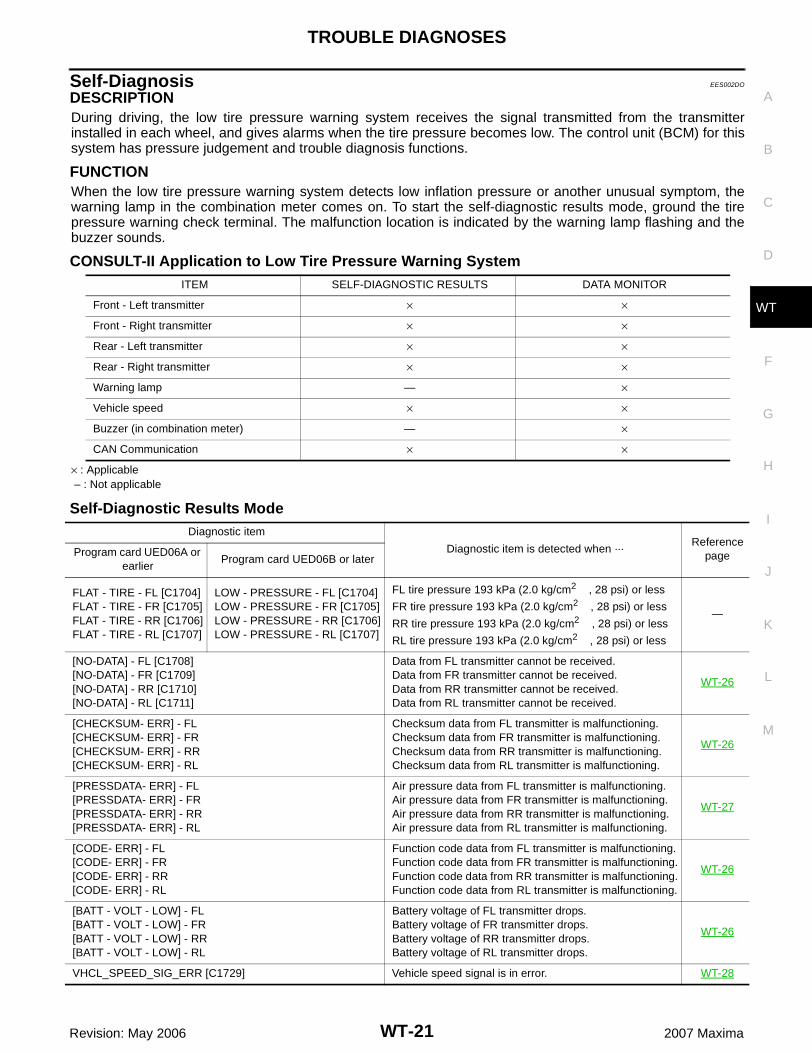
Self-Diagnosis EES002DO
DESCRIPTIONDuring driving, the low tire pressure warning system receives the signal transmitted from the transmitterinstalled in each wheel, and gives alarms when the tire pressure becomes low. The control unit (BCM) for thissystem has pressure judgement and trouble diagnosis functions.
FUNCTIONWhen the low tire pressure warning system detects low inflation pressure or another unusual symptom, thewarning lamp in the combination meter comes on. To start the self-diagnostic results mode, ground the tirepressure warning check terminal. The malfunction location is indicated by the warning lamp flashing and thebuzzer sounds.
CONSULT-II Application to Low Tire Pressure Warning System
× : Applicable – : Not applicable
Self-Diagnostic Results Mode
ITEM SELF-DIAGNOSTIC RESULTS DATA MONITOR
Front - Left transmitter × ×
Front - Right transmitter × ×
Rear - Left transmitter × ×
Rear - Right transmitter × ×
Warning lamp — ×
Vehicle speed × ×
Buzzer (in combination meter) — ×
CAN Communication × ×
Diagnostic item
Diagnostic item is detected when ···Reference
pageProgram card UED06A or earlier
Program card UED06B or later
FLAT - TIRE - FL [C1704]FLAT - TIRE - FR [C1705]FLAT - TIRE - RR [C1706]FLAT - TIRE - RL [C1707]
LOW - PRESSURE - FL [C1704]LOW - PRESSURE - FR [C1705]LOW - PRESSURE - RR [C1706]LOW - PRESSURE - RL [C1707]
FL tire pressure 193 kPa (2.0 kg/cm2 , 28 psi) or less
FR tire pressure 193 kPa (2.0 kg/cm2 , 28 psi) or less
RR tire pressure 193 kPa (2.0 kg/cm2 , 28 psi) or less
RL tire pressure 193 kPa (2.0 kg/cm2 , 28 psi) or less
—
[NO-DATA] - FL [C1708][NO-DATA] - FR [C1709][NO-DATA] - RR [C1710][NO-DATA] - RL [C1711]
Data from FL transmitter cannot be received.Data from FR transmitter cannot be received.Data from RR transmitter cannot be received.Data from RL transmitter cannot be received.
WT-26
[CHECKSUM- ERR] - FL[CHECKSUM- ERR] - FR[CHECKSUM- ERR] - RR[CHECKSUM- ERR] - RL
Checksum data from FL transmitter is malfunctioning.Checksum data from FR transmitter is malfunctioning.Checksum data from RR transmitter is malfunctioning.Checksum data from RL transmitter is malfunctioning.
WT-26
[PRESSDATA- ERR] - FL[PRESSDATA- ERR] - FR[PRESSDATA- ERR] - RR[PRESSDATA- ERR] - RL
Air pressure data from FL transmitter is malfunctioning.Air pressure data from FR transmitter is malfunctioning.Air pressure data from RR transmitter is malfunctioning.Air pressure data from RL transmitter is malfunctioning.
WT-27
[CODE- ERR] - FL[CODE- ERR] - FR[CODE- ERR] - RR[CODE- ERR] - RL
Function code data from FL transmitter is malfunctioning.Function code data from FR transmitter is malfunctioning.Function code data from RR transmitter is malfunctioning.Function code data from RL transmitter is malfunctioning.
WT-26
[BATT - VOLT - LOW] - FL[BATT - VOLT - LOW] - FR[BATT - VOLT - LOW] - RR[BATT - VOLT - LOW] - RL
Battery voltage of FL transmitter drops.Battery voltage of FR transmitter drops.Battery voltage of RR transmitter drops.Battery voltage of RL transmitter drops.
WT-26
VHCL_SPEED_SIG_ERR [C1729] Vehicle speed signal is in error. WT-28
WT-22
TROUBLE DIAGNOSES
Revision: May 2006 2007 Maxima
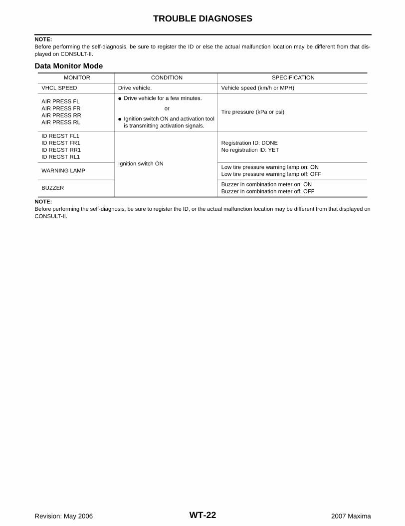
NOTE:Before performing the self-diagnosis, be sure to register the ID or else the actual malfunction location may be different from that dis-played on CONSULT-II.
Data Monitor Mode
NOTE:Before performing the self-diagnosis, be sure to register the ID, or the actual malfunction location may be different from that displayed onCONSULT-II.
MONITOR CONDITION SPECIFICATION
VHCL SPEED Drive vehicle. Vehicle speed (km/h or MPH)
AIR PRESS FLAIR PRESS FRAIR PRESS RRAIR PRESS RL
� Drive vehicle for a few minutes.
Tire pressure (kPa or psi)or
� Ignition switch ON and activation tool is transmitting activation signals.
ID REGST FL1ID REGST FR1ID REGST RR1ID REGST RL1
Ignition switch ON
Registration ID: DONENo registration ID: YET
WARNING LAMPLow tire pressure warning lamp on: ONLow tire pressure warning lamp off: OFF
BUZZERBuzzer in combination meter on: ONBuzzer in combination meter off: OFF
TROUBLE DIAGNOSES
WT-23
C
D
F
G
H
I
J
K
L
M
A
B
WT
Revision: May 2006 2007 Maxima
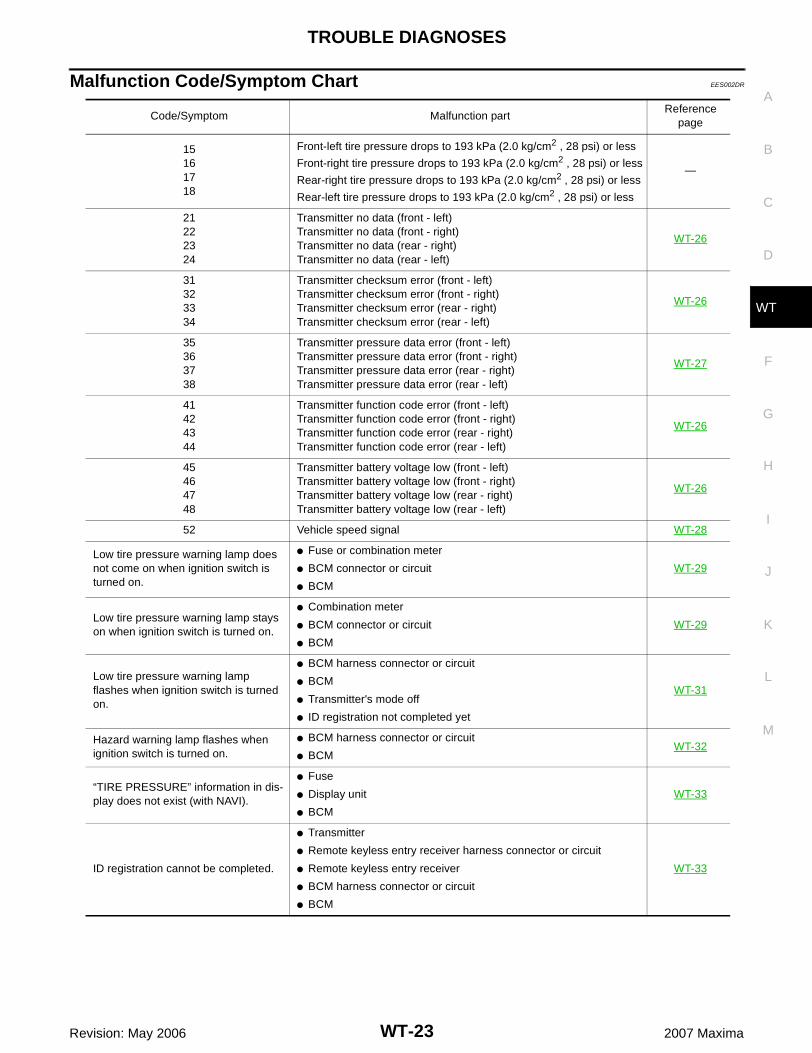
Malfunction Code/Symptom Chart EES002DR
Code/Symptom Malfunction partReference
page
15161718
Front-left tire pressure drops to 193 kPa (2.0 kg/cm2 , 28 psi) or less
Front-right tire pressure drops to 193 kPa (2.0 kg/cm2 , 28 psi) or less
Rear-right tire pressure drops to 193 kPa (2.0 kg/cm2 , 28 psi) or less
Rear-left tire pressure drops to 193 kPa (2.0 kg/cm2 , 28 psi) or less
—
21222324
Transmitter no data (front - left)Transmitter no data (front - right)Transmitter no data (rear - right)Transmitter no data (rear - left)
WT-26
31323334
Transmitter checksum error (front - left)Transmitter checksum error (front - right)Transmitter checksum error (rear - right)Transmitter checksum error (rear - left)
WT-26
35363738
Transmitter pressure data error (front - left)Transmitter pressure data error (front - right)Transmitter pressure data error (rear - right)Transmitter pressure data error (rear - left)
WT-27
41424344
Transmitter function code error (front - left)Transmitter function code error (front - right)Transmitter function code error (rear - right)Transmitter function code error (rear - left)
WT-26
45464748
Transmitter battery voltage low (front - left)Transmitter battery voltage low (front - right)Transmitter battery voltage low (rear - right)Transmitter battery voltage low (rear - left)
WT-26
52 Vehicle speed signal WT-28
Low tire pressure warning lamp does not come on when ignition switch is turned on.
� Fuse or combination meter
� BCM connector or circuit
� BCM
WT-29
Low tire pressure warning lamp stays on when ignition switch is turned on.
� Combination meter
� BCM connector or circuit
� BCM
WT-29
Low tire pressure warning lamp flashes when ignition switch is turned on.
� BCM harness connector or circuit
� BCM
� Transmitter's mode off
� ID registration not completed yet
WT-31
Hazard warning lamp flashes when ignition switch is turned on.
� BCM harness connector or circuit
� BCMWT-32
“TIRE PRESSURE” information in dis-play does not exist (with NAVI).
� Fuse
� Display unit
� BCM
WT-33
ID registration cannot be completed.
� Transmitter
� Remote keyless entry receiver harness connector or circuit
� Remote keyless entry receiver
� BCM harness connector or circuit
� BCM
WT-33
WT-24
TROUBLE DIAGNOSES
Revision: May 2006 2007 Maxima
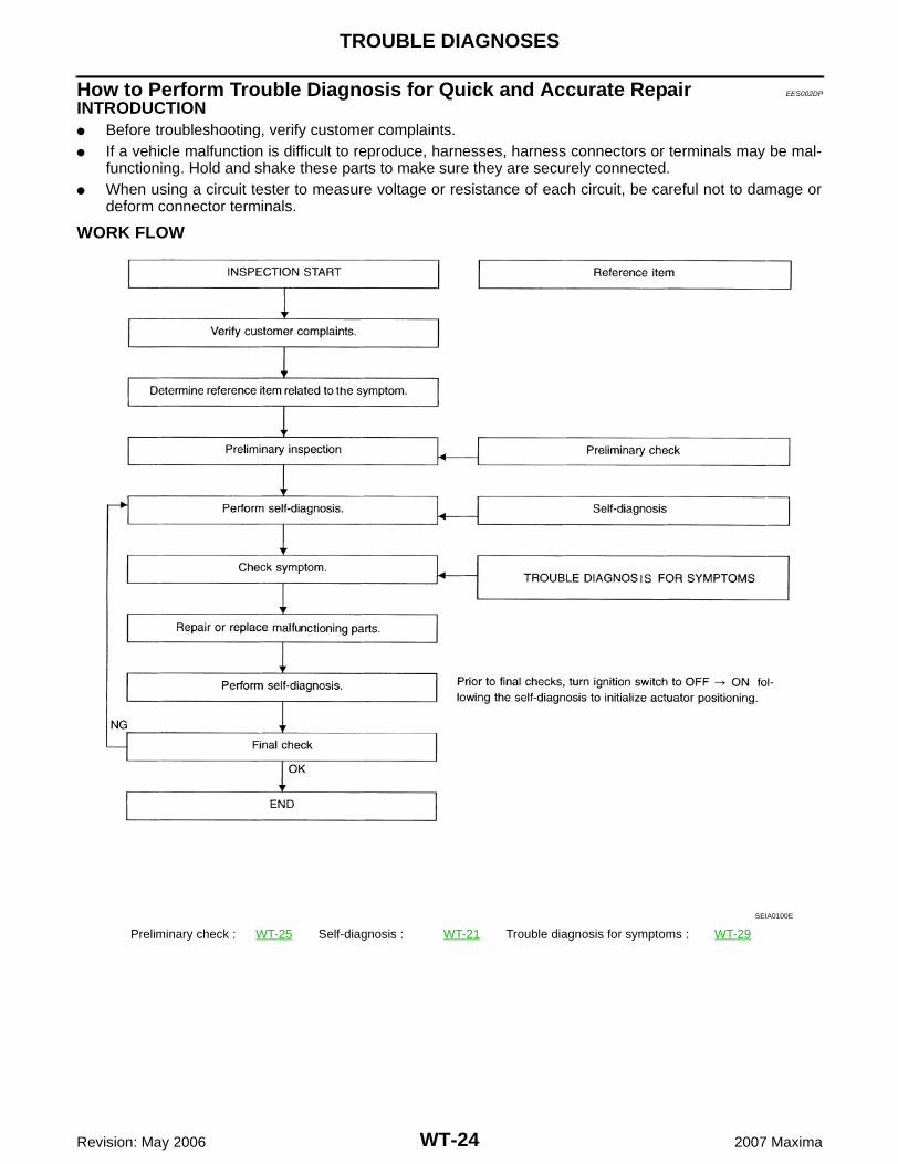
How to Perform Trouble Diagnosis for Quick and Accurate Repair EES002DP
INTRODUCTION� Before troubleshooting, verify customer complaints.� If a vehicle malfunction is difficult to reproduce, harnesses, harness connectors or terminals may be mal-
functioning. Hold and shake these parts to make sure they are securely connected.� When using a circuit tester to measure voltage or resistance of each circuit, be careful not to damage or
deform connector terminals.
WORK FLOW
Preliminary check : WT-25 Self-diagnosis : WT-21 Trouble diagnosis for symptoms : WT-29
SEIA0100E
TROUBLE DIAGNOSES
WT-25
C
D
F
G
H
I
J
K
L
M
A
B
WT
Revision: May 2006 2007 Maxima
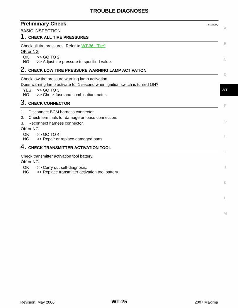
Preliminary Check EES002DQ
BASIC INSPECTION
1. CHECK ALL TIRE PRESSURES
Check all tire pressures. Refer to WT-36, "Tire" .OK or NGOK >> GO TO 2.NG >> Adjust tire pressure to specified value.
2. CHECK LOW TIRE PRESSURE WARNING LAMP ACTIVATION
Check low tire pressure warning lamp activation.Does warning lamp activate for 1 second when ignition switch is turned ON?YES >> GO TO 3.NO >> Check fuse and combination meter.
3. CHECK CONNECTOR
1. Disconnect BCM harness connector.2. Check terminals for damage or loose connection. 3. Reconnect harness connector.OK or NGOK >> GO TO 4.NG >> Repair or replace damaged parts.
4. CHECK TRANSMITTER ACTIVATION TOOL
Check transmitter activation tool battery.OK or NGOK >> Carry out self-diagnosis.NG >> Replace transmitter activation tool battery.
WT-26
TROUBLE DIAGNOSIS FOR SELF-DIAGNOSTIC ITEMS
Revision: May 2006 2007 Maxima
TROUBLE DIAGNOSIS FOR SELF-DIAGNOSTIC ITEMS PFP:00000
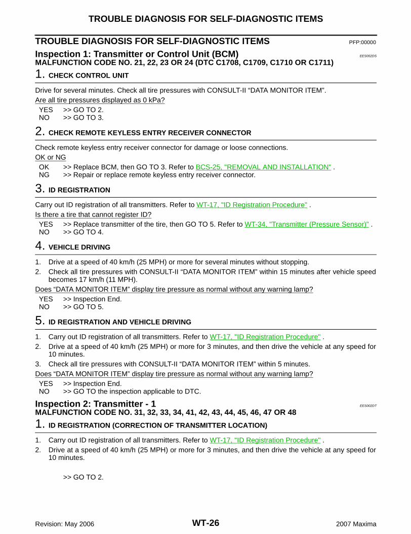
Inspection 1: Transmitter or Control Unit (BCM) EES002DS
MALFUNCTION CODE NO. 21, 22, 23 OR 24 (DTC C1708, C1709, C1710 OR C1711)
1. CHECK CONTROL UNIT
Drive for several minutes. Check all tire pressures with CONSULT-II “DATA MONITOR ITEM”.Are all tire pressures displayed as 0 kPa?YES >> GO TO 2.NO >> GO TO 3.
2. CHECK REMOTE KEYLESS ENTRY RECEIVER CONNECTOR
Check remote keyless entry receiver connector for damage or loose connections.OK or NGOK >> Replace BCM, then GO TO 3. Refer to BCS-25, "REMOVAL AND INSTALLATION" .NG >> Repair or replace remote keyless entry receiver connector.
3. ID REGISTRATION
Carry out ID registration of all transmitters. Refer to WT-17, "ID Registration Procedure" .Is there a tire that cannot register ID?YES >> Replace transmitter of the tire, then GO TO 5. Refer to WT-34, "Transmitter (Pressure Sensor)" .NO >> GO TO 4.
4. VEHICLE DRIVING
1. Drive at a speed of 40 km/h (25 MPH) or more for several minutes without stopping.2. Check all tire pressures with CONSULT-II “DATA MONITOR ITEM” within 15 minutes after vehicle speed
becomes 17 km/h (11 MPH).Does “DATA MONITOR ITEM” display tire pressure as normal without any warning lamp?YES >> Inspection End.NO >> GO TO 5.
5. ID REGISTRATION AND VEHICLE DRIVING
1. Carry out ID registration of all transmitters. Refer to WT-17, "ID Registration Procedure" .2. Drive at a speed of 40 km/h (25 MPH) or more for 3 minutes, and then drive the vehicle at any speed for
10 minutes.3. Check all tire pressures with CONSULT-II “DATA MONITOR ITEM” within 5 minutes.Does “DATA MONITOR ITEM” display tire pressure as normal without any warning lamp?YES >> Inspection End.NO >> GO TO the inspection applicable to DTC.
Inspection 2: Transmitter - 1 EES002DT
MALFUNCTION CODE NO. 31, 32, 33, 34, 41, 42, 43, 44, 45, 46, 47 OR 48
1. ID REGISTRATION (CORRECTION OF TRANSMITTER LOCATION)
1. Carry out ID registration of all transmitters. Refer to WT-17, "ID Registration Procedure" .2. Drive at a speed of 40 km/h (25 MPH) or more for 3 minutes, and then drive the vehicle at any speed for
10 minutes.
>> GO TO 2.

TROUBLE DIAGNOSIS FOR SELF-DIAGNOSTIC ITEMS
WT-27
C
D
F
G
H
I
J
K
L
M
A
B
WT
Revision: May 2006 2007 Maxima
2. REPLACE TRANSMITTER
1. Check low tire pressure warning lamp again for flashing, replace malfunctioning transmitter.2. Carry out ID registration of all transmitters. Refer to WT-17, "ID Registration Procedure" .Can ID registration of all transmitters be completed?YES >> GO TO 3.NO >> GO TO Inspection 1. Refer to WT-26, "Inspection 1: Transmitter or Control Unit (BCM)" .
3. VEHICLE DRIVING
1. Drive at a speed of 40 km/h (25 MPH) or more for 3 minutes, and then drive the vehicle at any speed for10 minutes.
2. Check all tire pressures with CONSULT-II “DATA MONITOR ITEM” within 5 minutes.Does “DATA MONITOR ITEM” display tire pressure as normal without any warning lamp?YES >> Inspection End.NO >> Replace malfunctioning transmitter, and perform Step 3 again. Refer to WT-34, "Transmitter
(Pressure Sensor)" .
Inspection 3: Transmitter - 2 EES002DU
MALFUNCTION CODE NO. 35, 36, 37 OR 38
1. CHECK ALL TIRE PRESSURES
Check all tire pressures. Refer to WT-36, "Tire" .Are there any tires with pressure of 64 psi or more?YES >> Adjust tire pressure to specified value.NO >> GO TO 2.
2. VEHICLE DRIVING
1. Carry out ID registration of all transmitters. Refer to WT-17, "ID Registration Procedure" .2. Drive at a speed of 40 km/h (25 MPH) or more for several minutes without stopping.3. Check all tire pressures with CONSULT-II “DATA MONITOR ITEM” within 15 minutes after vehicle speed
becomes 17 km/h (11 MPH).Does “DATA MONITOR ITEM” display 64 psi or more?YES >> Replace transmitter. Refer to WT-34, "Transmitter (Pressure Sensor)" . GO TO 3.NO >> GO TO 3.
3. ID REGISTRATION AND VEHICLE DRIVING
1. Carry out ID registration of all transmitters. Refer to WT-17, "ID Registration Procedure" .2. Drive at a speed of 40 km/h (25 MPH) or more for 3 minutes, and then drive the vehicle at any speed for
10 minutes.3. Check all tire pressures with CONSULT-II “DATA MONITOR ITEM” within 5 minutes.Does “DATA MONITOR ITEM” display tire pressure as normal without any warning lamp?YES >> Inspection End.NO >> GO TO the inspection applicable to DTC.
WT-28
TROUBLE DIAGNOSIS FOR SELF-DIAGNOSTIC ITEMS
Revision: May 2006 2007 Maxima
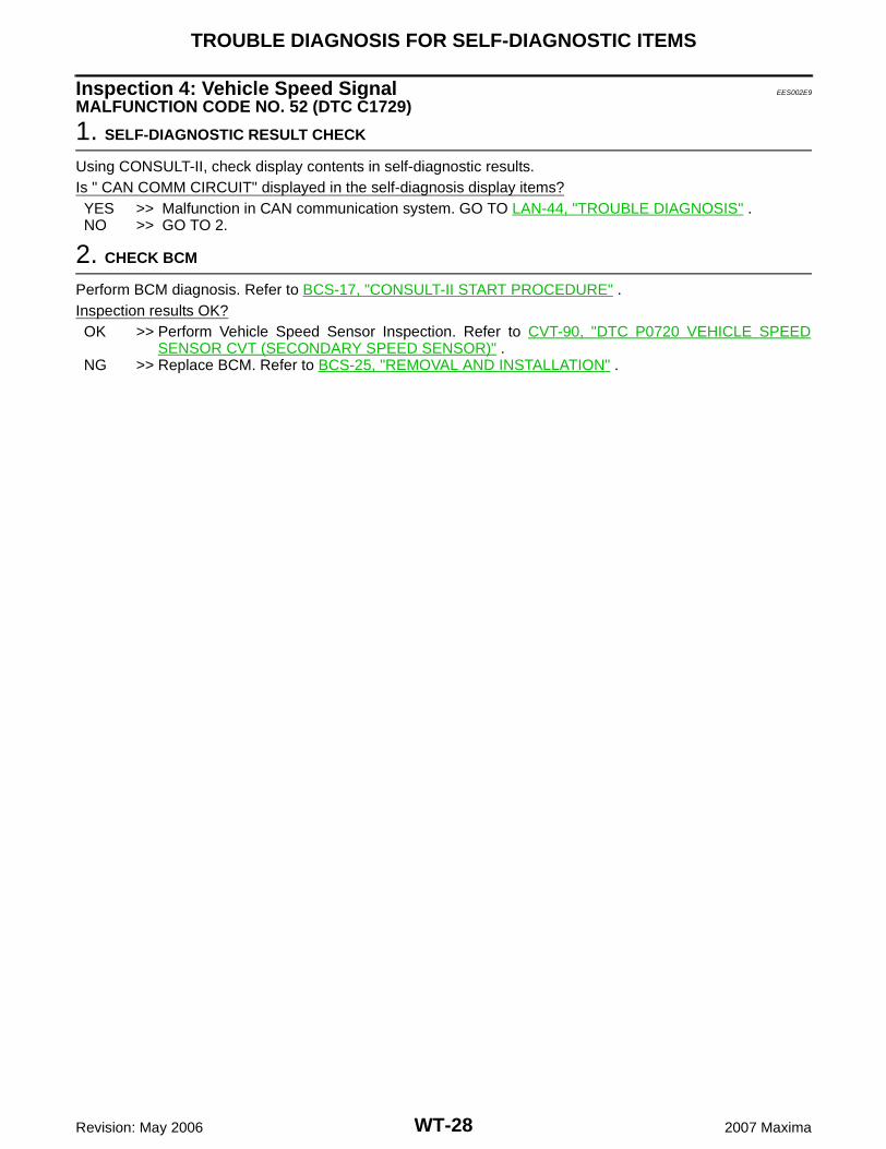
Inspection 4: Vehicle Speed Signal EES002E9
MALFUNCTION CODE NO. 52 (DTC C1729)
1. SELF-DIAGNOSTIC RESULT CHECK
Using CONSULT-II, check display contents in self-diagnostic results.Is " CAN COMM CIRCUIT" displayed in the self-diagnosis display items?YES >> Malfunction in CAN communication system. GO TO LAN-44, "TROUBLE DIAGNOSIS" .NO >> GO TO 2.
2. CHECK BCM
Perform BCM diagnosis. Refer to BCS-17, "CONSULT-II START PROCEDURE" .Inspection results OK?OK >> Perform Vehicle Speed Sensor Inspection. Refer to CVT-90, "DTC P0720 VEHICLE SPEED
SENSOR CVT (SECONDARY SPEED SENSOR)" .NG >> Replace BCM. Refer to BCS-25, "REMOVAL AND INSTALLATION" .
TROUBLE DIAGNOSIS FOR SYMPTOMS
WT-29
C
D
F
G
H
I
J
K
L
M
A
B
WT
Revision: May 2006 2007 Maxima
TROUBLE DIAGNOSIS FOR SYMPTOMS PFP:00007
Inspection 1: Warning Lamp Does Not Come On When Ignition Switch Is Turned On. EES002EA
DIAGNOSTIC PROCEDURE
1. SELF-DIAGNOSTIC RESULT CHECK
Using CONSULT-II, check display contents in self-diagnostic results.Is "CAN COMM CIRCUIT" displayed in the self-diagnosis display items?YES >> Malfunction in CAN communication system. GO TO LAN-44, "TROUBLE DIAGNOSIS" .NO >> GO TO 2.
2. CHECK COMBINATION METER
Check combination meter operation.Inspection results OK?OK >> GO TO 3.NG >> Check combination meter. Refer to DI-13, "Self-Diagnosis Mode of Combination Meter" .
3. CHECK LOW TIRE PRESSURE WARNING LAMP
Disconnect BCM harness connector. Does the low tire pressure warning lamp activate?YES >> Replace BCM. Refer to BCS-25, "REMOVAL AND INSTALLATION" .NO >> Check combination meter and repair or replace.
Inspection 2: Warning Lamp Stays On When Ignition Switch Is Turned On EES002DX
DIAGNOSTIC PROCEDURE
1. CHECK CONNECTOR
1. Turn ignition switch OFF.2. Disconnect BCM harness connectors M18 and M20.3. Check terminals for damage or loose connections.Inspection results OK?OK >> GO TO 2.NG >> Repair or replace damaged parts.
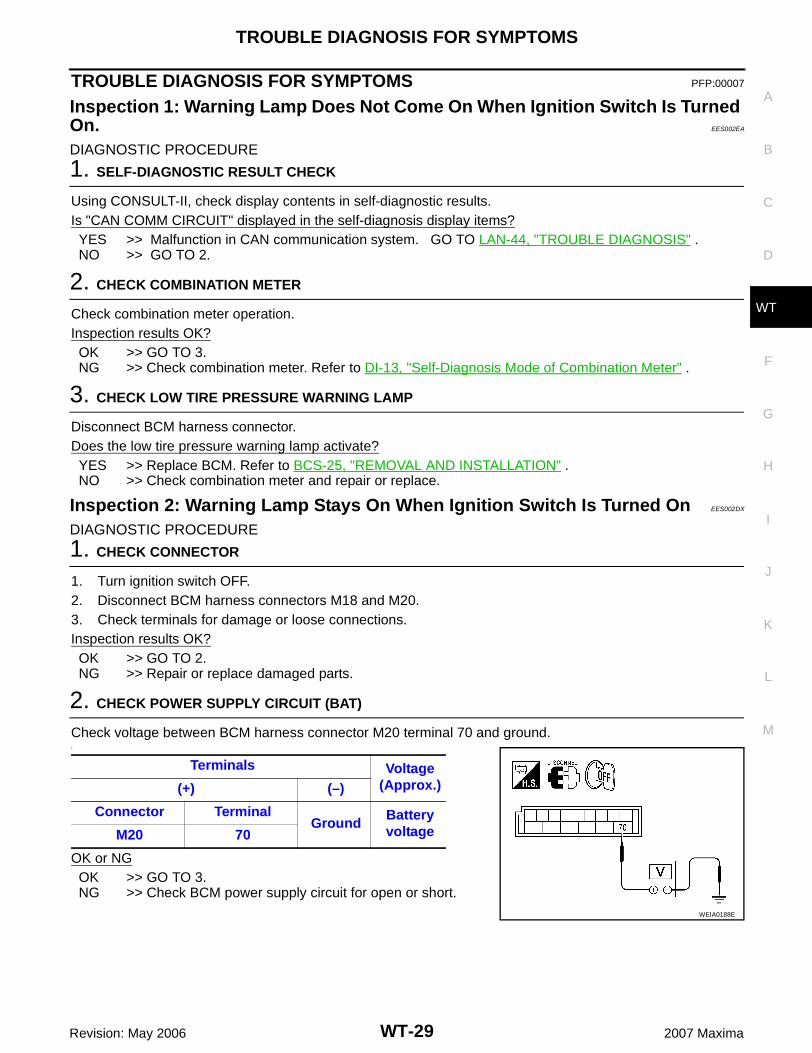
2. CHECK POWER SUPPLY CIRCUIT (BAT)
Check voltage between BCM harness connector M20 terminal 70 and ground.1.
OK or NGOK >> GO TO 3.NG >> Check BCM power supply circuit for open or short.
Terminals Voltage(Approx.)(+) (–)
Connector TerminalGround
Battery voltageM20 70
WEIA0188E
WT-30
TROUBLE DIAGNOSIS FOR SYMPTOMS
Revision: May 2006 2007 Maxima
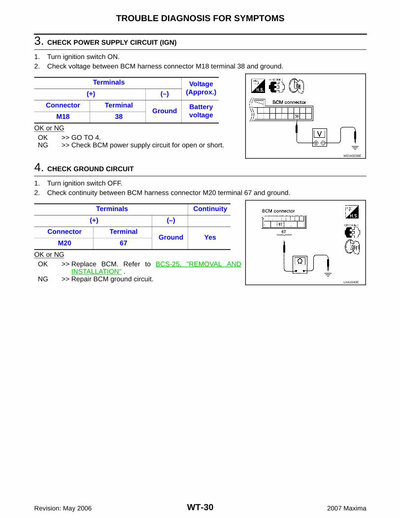
3. CHECK POWER SUPPLY CIRCUIT (IGN)
1. Turn ignition switch ON.2. Check voltage between BCM harness connector M18 terminal 38 and ground.
OK or NGOK >> GO TO 4.NG >> Check BCM power supply circuit for open or short.
4. CHECK GROUND CIRCUIT
1. Turn ignition switch OFF.2. Check continuity between BCM harness connector M20 terminal 67 and ground.
OK or NGOK >> Replace BCM. Refer to BCS-25, "REMOVAL AND
INSTALLATION" .NG >> Repair BCM ground circuit.
Terminals Voltage(Approx.)(+) (–)
Connector TerminalGround
Battery voltageM18 38
WEIA0038E
Terminals Continuity
(+) (–)
Connector TerminalGround Yes
M20 67
LIIA1040E
TROUBLE DIAGNOSIS FOR SYMPTOMS
WT-31
C
D
F
G
H
I
J
K
L
M
A
B
WT
Revision: May 2006 2007 Maxima
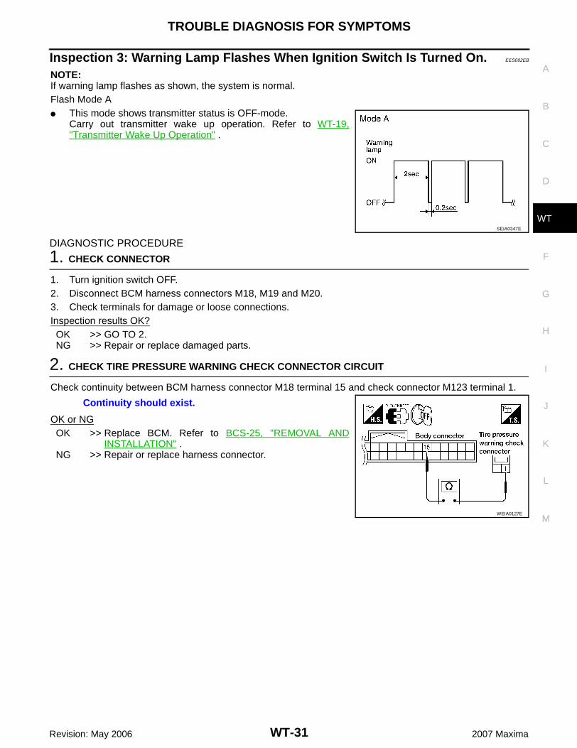
Inspection 3: Warning Lamp Flashes When Ignition Switch Is Turned On. EES002EB
NOTE:If warning lamp flashes as shown, the system is normal.Flash Mode A� This mode shows transmitter status is OFF-mode.
Carry out transmitter wake up operation. Refer to WT-19,"Transmitter Wake Up Operation" .
DIAGNOSTIC PROCEDURE
1. CHECK CONNECTOR
1. Turn ignition switch OFF.2. Disconnect BCM harness connectors M18, M19 and M20.3. Check terminals for damage or loose connections.Inspection results OK?OK >> GO TO 2.NG >> Repair or replace damaged parts.
2. CHECK TIRE PRESSURE WARNING CHECK CONNECTOR CIRCUIT
Check continuity between BCM harness connector M18 terminal 15 and check connector M123 terminal 1.
OK or NGOK >> Replace BCM. Refer to BCS-25, "REMOVAL AND
INSTALLATION" .NG >> Repair or replace harness connector.
SEIA0347E
Continuity should exist.
WEIA0127E
WT-32
TROUBLE DIAGNOSIS FOR SYMPTOMS
Revision: May 2006 2007 Maxima
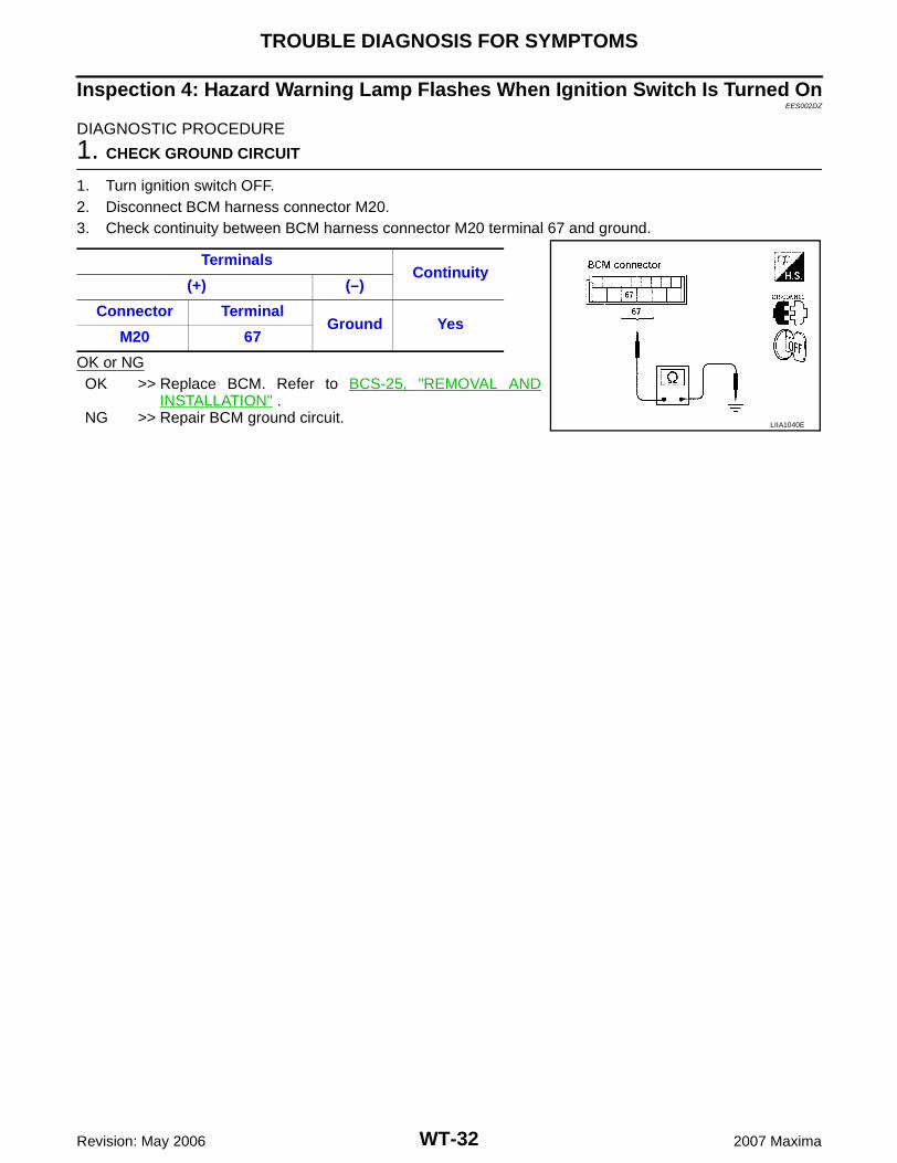
Inspection 4: Hazard Warning Lamp Flashes When Ignition Switch Is Turned OnEES002DZ
DIAGNOSTIC PROCEDURE
1. CHECK GROUND CIRCUIT
1. Turn ignition switch OFF.2. Disconnect BCM harness connector M20.3. Check continuity between BCM harness connector M20 terminal 67 and ground.
OK or NGOK >> Replace BCM. Refer to BCS-25, "REMOVAL AND
INSTALLATION" .NG >> Repair BCM ground circuit.
TerminalsContinuity
(+) (–)
Connector TerminalGround Yes
M20 67
LIIA1040E
TROUBLE DIAGNOSIS FOR SYMPTOMS
WT-33
C
D
F
G
H
I
J
K
L
M
A
B
WT
Revision: May 2006 2007 Maxima
Inspection 5: “TIRE PRESSURE” Information In Display Unit Does Not Exist.EES002EC
DIAGNOSTIC PROCEDURE
1. SELF-DIAGNOSTIC RESULT CHECK
Using CONSULT-II, check display contents in self-diagnostic results.Is "CAN COMM CIRCUIT" displayed in the self-diagnosis display items?YES >> Malfunction in CAN communication system. GO TO LAN-44, "TROUBLE DIAGNOSIS" .NO >> GO TO 2.
2. CHECK DISPLAY UNIT
Perform display unit self-diagnosis. Refer to AV-154, "Self-Diagnosis Mode (NAVI)" .Inspection results OK?OK >> Replace BCM. Refer to BCS-25, "REMOVAL AND INSTALLATION" .NG >> Repair or replace malfunctioning parts.
Inspection 6: ID Registration Cannot Be Completed EES002E1
DIAGNOSTIC PROCEDURE
1. ID REGISTRATION (ALL)
Carry out ID registration of all transmitters. Refer to WT-17, "ID Registration Procedure" .Can ID registration of all transmitters be completed?YES >> Inspection End.NO >> GO TO WT-26, "Inspection 1: Transmitter or Control Unit (BCM)" .
WT-34
REMOVAL AND INSTALLATION
Revision: May 2006 2007 Maxima
REMOVAL AND INSTALLATION PFP:00000
Transmitter (Pressure Sensor) EES002E2
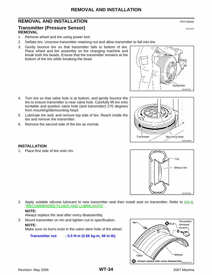
REMOVAL1. Remove wheel and tire using power tool.2. Deflate tire. Unscrew transmitter retaining nut and allow transmitter to fall into tire.3. Gently bounce tire so that transmitter falls to bottom of tire.
Place wheel and tire assembly on tire changing machine andbreak both tire beads. Ensure that the transmitter remains at thebottom of the tire while breaking the bead.
4. Turn tire so that valve hole is at bottom, and gently bounce thetire to ensure transmitter is near valve hole. Carefully lift tire ontoturntable and position valve hole (and transmitter) 270 degreesfrom mounting/dismounting head.
5. Lubricate tire well, and remove top side of tire. Reach inside thetire and remove the transmitter.
6. Remove the second side of the tire as normal.
INSTALLATION1. Place first side of tire onto rim.
2. Apply suitable silicone lubricant to new transmitter seal then install seal on transmitter. Refer to MA-9,"RECOMMENDED FLUIDS AND LUBRICANTS" .NOTE:Always replace the seal after every disassembly.
3. Mount transmitter on rim and tighten nut to specification.NOTE:Make sure no burrs exist in the valve stem hole of the wheel.
SEIA0047E
WEIA0046E
SEIA0049E
Transmitter nut : 5.5 N·m (0.56 kg-m, 49 in-lb)
WEIA0137E
REMOVAL AND INSTALLATION
WT-35
C
D
F
G
H
I
J
K
L
M
A
B
WT
Revision: May 2006 2007 Maxima
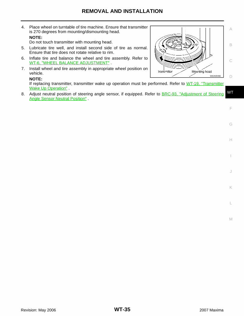
4. Place wheel on turntable of tire machine. Ensure that transmitteris 270 degrees from mounting/dismounting head.NOTE:Do not touch transmitter with mounting head.
5. Lubricate tire well, and install second side of tire as normal.Ensure that tire does not rotate relative to rim.
6. Inflate tire and balance the wheel and tire assembly. Refer toWT-6, "WHEEL BALANCE ADJUSTMENT" .
7. Install wheel and tire assembly in appropriate wheel position onvehicle.NOTE:If replacing transmitter, transmitter wake up operation must be performed. Refer to WT-19, "TransmitterWake Up Operation" .
8. Adjust neutral position of steering angle sensor, if equipped. Refer to BRC-93, "Adjustment of SteeringAngle Sensor Neutral Position" .
WEIA0046E

WT-36
SERVICE DATA AND SPECIFICATIONS (SDS)
Revision: May 2006 2007 Maxima
SERVICE DATA AND SPECIFICATIONS (SDS) PFP:00030
Road Wheel EES0019H
Tire EES0019I
Unit: kPa (kg/cm2 , psi)
*: D or R depending on manufacturer
*1 : United States
*2 : Optional in United States; standard in Canada
Wheel type Aluminum
Maximum radial runout limitLateral mm (in) 0.3 (0.012) or less
Radial mm (in) 0.3 (0.012) or less
Allowable quantity of residual unbal-ance
Dynamic (On the ear part)
Less than 5 g (0.18 oz.) (per side)
Static (On the ear part) Less than 10 g (0.35 oz.)
Tire sizeAir pressure
Conventional tire Spare tire
T145/80*17 — 420 (4.2, 60) *1
225/55R17 230 (2.3, 33) 230 (2.3, 33) *2
245/45R18 220 (2.2, 32) 220 (2.2, 32) *2