SECTION M - Spridgetguru.com · 2017-10-12 · hand brake mounted alongside the propeller shaft...
14
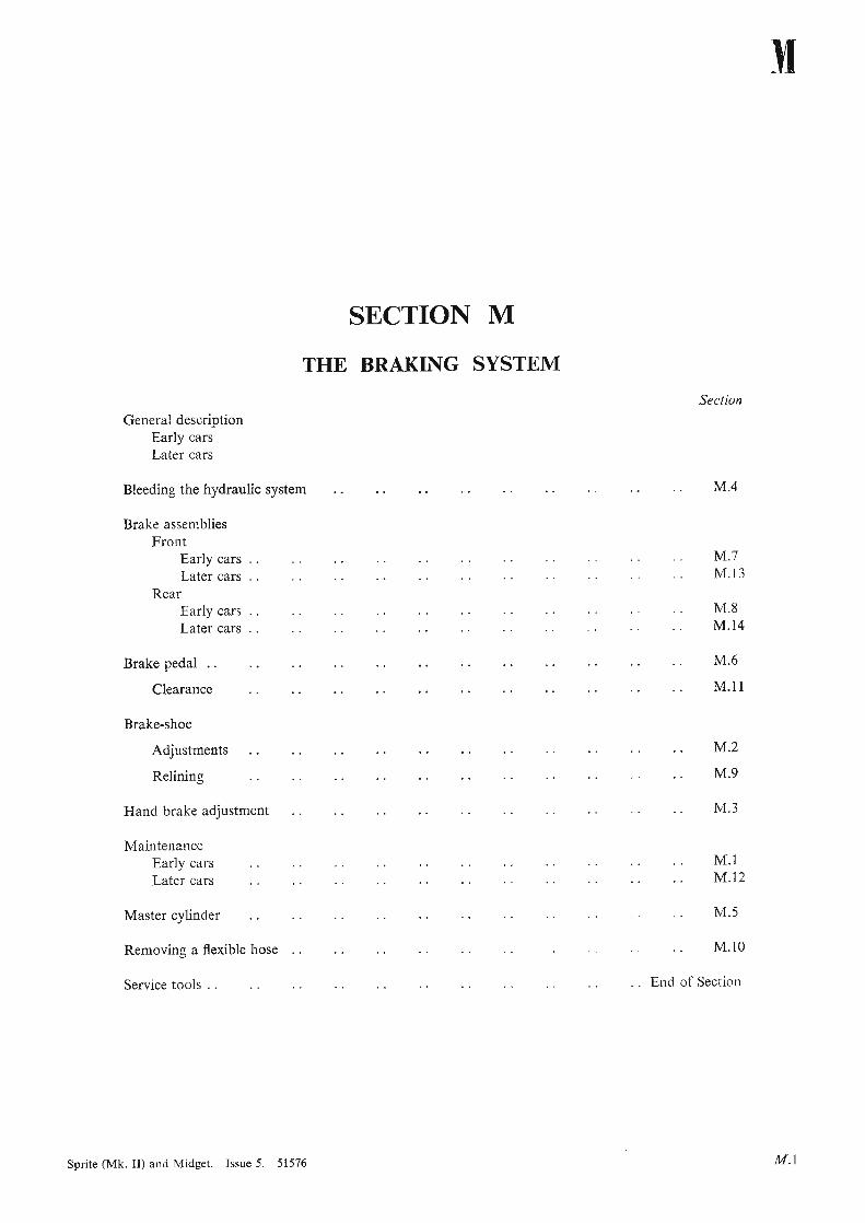
SECTION M THE BRAKING SYSTEM General description Early cars Later cars Bleeding the hydraulic system Brake assemblies Front Early cars Later cars Rear Early cars Later cars Bra ke pedal .. Clearance Brake-shoe Adjustments Relining Hand brake adjustment Mai ntenance Early cars Later cars Master cylinder Removin g a flexible hose Service too ls . . Sprite (Mk. II) and Midget. Issue 5. 51576 Brake pedal .. Se ction M.4 M.7 M. 13 M.8 M .14 M.6 M.ll M.2 M.9 M.3 M .l M.1 2 M. 5 M.lO End of Section M.6 M M.I
Transcript of SECTION M - Spridgetguru.com · 2017-10-12 · hand brake mounted alongside the propeller shaft...
SECTION M
THE BRAKING SYSTEM
General descriptionEarly carsLater cars
Bleeding the hydraulic system
Brake assembliesFront
Early carsLater cars
RearEarly carsLater cars
Bra ke pedal . .
Clearance
Brake-shoe
Adjustments
Relining
Ha nd brake adjus tment
Mai ntenanceEarly carsLater cars
Master cylinder
Removin g a flexible hose
Service too ls . .
Sprite (Mk . II) and Midget. Issue 5. 51576
Brake pedal . .
Section
M.4
M.7M. 13
M.8M .14
M.6
M.ll
M.2
M.9
M.3
M .lM.1 2
M. 5
M. lO
End of Section
M.6
M
M.I
TH
EF
RO
NT
BR
AK
EC
OM
PO
NE
NT
S""""'"
""
'"''''
""
""
""
"""~
B12
30
19 i--
14~--
13
8'---
-12
6-
11
~9
6-
8
30
29
-.
39~
VJ
'0 .., §-"10
-~ 1""
?.... ~ III ::l C
o 3:: c:2
5O
Q ~ [I §I
="--
.1
111
1I
111
11
'1'
_-+
-+-+
++
+1.+
++
••
++
++
++
111
_1
'1·.--.
1'1
'+
'1.
"1
'1I"
1••
11
11
1"
".-.-
1.1
1"I
I'1
11
11
11
••
1•••
11
1'1
'...............
f4J
-6

KE
YT
OT
HE
FR
ON
TB
RA
KE
CO
MP
ON
EN
TS
Vl
1--
...11
1.1
11
1',.
1'
11
11
'11
11
11
11
._
-__
-...-
_.
'1
""
11
11
11
11
11
11
1'
11
11
11
1"
'1
_1
11
11
11
11
'1
'1
I1
11
1
-g. " ~ ".
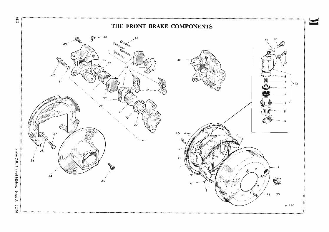
Des
crip
tion
29.
Cal
liper
unit
asse
mbl
y -L
.H.
30.
Cal
lipe
r -L
.R.
31.
Pist
on.
32.
Inne
rse
al.
33.
Du
stse
alan
dre
tain
er.
34.
Pad
asse
mbl
y.
35.
Pad
reta
inin
gsp
ring
.
36.
Split
cott
erpi
n.
37.
Pad
shim
.
38.
Plug
.
39.
Ble
edsc
rew
.
40.
Cal
liper
mo
unti
ngbo
lt.
4l.
Spri
ngw
ashe
r.
No
.··-·
----
--1 i I 1 j i j
No
.D
escr
ipti
on
15.
Seal
ing
ring
.
16.
Set
scre
w(s
mal
l).
17.
Spri
ngw
ashe
r.
18.
Set
scre
w(l
arge
).
19.
Spri
ngw
ashe
r.
20.
Ble
eder
scre
w.
21.
Bra
ke-d
rum
.
22.
Set
scre
w.
23.
Plu
g.
24.
Bra
ke
disc
.
25.
Set
scre
w.
26.
Dus
tco
ver.
27.
Set
scre
w.
28.
Sha
kepr
oof
was
her.
No
.D
escr
ipti
on
I.B
rake
-pla
te.
2.Se
tsc
rew
.
3.Sh
akep
roo
fw
ashe
r.
4.B
rake
-sho
eas
sem
bly.
5.L
iner
wit
hri
vets
.
6.R
ivet
.
7.Pu
ll-of
fsp
ring
.
8.M
icra
mad
just
er.
9.M
ask
.
10.
Wh
eel
cyli
nder
asse
mbl
y.
II.
Pis
ton
with
dus
tco
ver.
12.
Cu
p.
13.
Cu
pfi
ller.
14.
Spri
ng.
~I.,
,,,,,
,,,,
,,,,
,,,
8.M
icra
mad
just
er.
22.
Set
scre
w.
36.
Split
cott
erpi
n.

M THE BRAKING SYSTEM
GENERAL DESCRIPTION(Early Cars)
The brakes on all four wheels are hydraulicallyoperated by pedal directly coupled to a master cylinder inwhich the hydraulic pressure of the brake operatingfluid is generated. A supply tank cast integrally with the
Fig. M. I
Showing afront brak e-drum with one ofthe brake-shoeadjusters
master cylinder replenishes the fluid, and a pipe lineconsisting of tubes and flexible hoses interconnects themaster cylinder and wheel cylinders.
The pressure generated in the master cylinder byapplication with the foot pedal is transmitted with equaland undiminished force to all wheel cylinders simultaneously. This moves the pistons outwards, which intum expand the brake-shoes, thus producing automaticequalization and efficiency in direct proportion to theeffort applied at the pedal.
When the pedal is released the brake-shoe springsreturn the shoes, which then return the wheel cylinderpistons, and therefore the fluid, to the pipe lines andmaster cylinder .
An independent mechanical linkage, actuated by ahand brake mounted alongside the propeller shaft tunnel,operates the rear brakes by mechanical expandersattached to the rear wheel cylinder bodies.
The front brakes are of the two-leading-shoe type withsliding shoes, which ensure automatic centralization ofthe brake-shoe in operation.
The rear brake s are also fitted with sliding shoes.
GENERAL DESCRIPTION(Later Cars)
The front brakes are of the rotating disc and rigidly
M.4
mounted calliper type, each calliper containing twofriction pad assemblies between which the disc rota tes.The friction pads are applied to the disc by means of twopistons operated by hydrau lic pressure, and are automatically retracted when the hydra ulic pressure is released.Wear on the friction pad s is taken up automatical1y andno adjustment is necessary.
When the friction pads require renewal they are readilydetachable without removing the calliper from itsmounting.
Fluid pressure generated in the master cylinder by theapplication of the brake pedal enters the mounting halfof the calliper and passes thro ugh internal fluid passagesto the rim half, thus exerting equal pressure on bothoperating pistons simultaneous ly and bringing thefriction pads into contact with the disc faces.
The pistons are sealed by means of a rubb er seal fittedto the mouth of the bore of each half of the calliper toprevent moisture and dirt from entering, and are alsosealed by a rubber seal fitted in a groove in each calliperbore to prevent fluid leakage.
The fluid seals grip the outer diameter of the pistonstightly.
When the brakes are applied outward movement ofthe piston and fluid pressure tend to force the seal outof its groove. As the pressure is released the seal returnsto its original position, and in doing so moves the pistonbackwards slightly to provide a running clearancebetween the friction pads and the disc. As the pads wearthe piston will move farther outwards to compensatefor the wear, thus eliminat ing the need for manualadjustment.
The rear brakes are of the internal-expanding typewith one leading and one trailing shoe in each assembly.Pressure on the pedal expand s the shoes in the drumshydraulically, and when the pressure is released returnsprings retract them onto their stops on the expanderunits.
A57 45
Fig. M .2
Showing rear brak e-shoe adjuster
Sprit e (Mk . II) and Midget. Issue 2. 51576
adjustment .The rear brakes are of the internal-expanding type
THE BRAKING SYSTEM MSection M.I
MAINTENANCE(Early Cars)
Periodically examine the quantity of brake fluid in themaster cylinder . The level should be kept i in. (6'5 mm.)below the bottom of the filler neck, but not higher. Thenecessity for frequent topping up is an indication ofoverfilling or a leak in the system which should at oncebe traced and rectified.
IMPORTANT.-Serious consequences may result fromthe use of incorrect fluids, and LOCKHEED SUPERHEAVY DUTY BRAKE FLUID or a fluid conformingto Specification S.A.E. 70.R3 must be used. This fluid hasbeen specially prepared and is unaffected by high temperature or freezing.
Adjust the brake-shoes to compensate for wear; theneed for this is shown by excessive pedal travel beforesolid resistance is felt. For brake adjustments see SectionsM.2 and M.3.
LubricationThere is one lubricating nipple on the top of the hand
brake compensating lever, and this is accessible fromunderneath the rear of the car. Wipe away all the dirtfrom the nipple and give one or two strokes at regularintervals with a gun filled with lubricant.
The hand brake cable nipple located just forward ofthe rear axle must receive three or four strokes at regularinterva ls with a gun filled with lubricant .
Section M.2BRAKE-SHOE ADJUSTMENTS
The brakes are adju sted for lining wear only at the shoesthemselves, and on no account should any alteration bemade to the hand brake cable for this purpose.
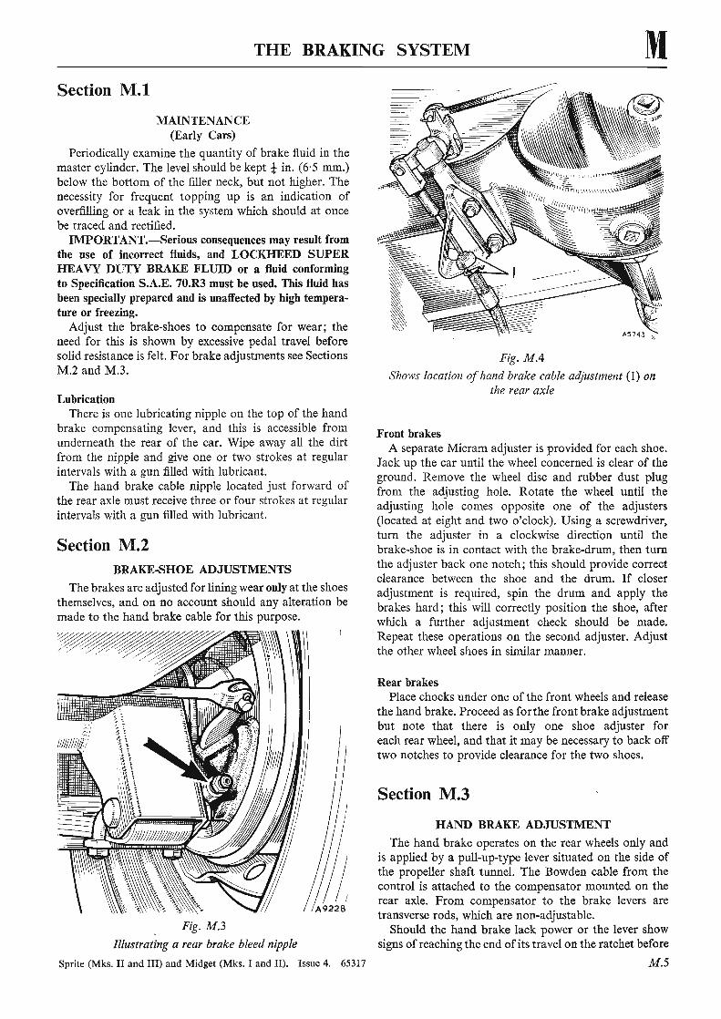
Fig. M.3
Illustrating a rear brake bleed nipple
Sprite (Mks. II and III) and Midget (Mk s. I and II). Issue 4. 65317
Section M.2
Fig. M.4
Shows location ofhand brake cable adjustment (1) onthe rear axle
Front brakesA separate Micram adjuster is provided for each shoe.
Jack up the car until the wheel concerned is clear of theground . Remove the wheel disc and rubber dust plugfrom the adjusting hole. Rotate the wheel until theadjusti ng hole comes opposite one of the adjusters(located at eight and two o'clock). Using a screwdriver,turn the adjuster in a clockwise direction until thebrake-shoe is in contact with the brake-drum, then turnthe adjuster back one notch; this should provide correctclearance between the shoe and the drum. If closeradjustment is required, spin the drum and apply thebrakes hard ; this will correctly position the shoe, afterwhich a further adjustment check should be made.Repeat these operations on the second adjuster. Adjustthe other wheel shoes in similar manner.
Rear brakesPlace chocks under one of the front wheels and release
the hand brake. Proceed as for the front brake adjustmentbut note that there is only one shoe adjuster foreach rear wheel, and that it may be necessary to back offtwo notches to provide clearance for the two shoes.
Section M.3
HAND BRAKE ADJUSTMENT
The hand brake operates on the rear wheels only andis applied by a pull-up-type lever situated on the side ofthe propeller shaft tunnel. The Bowden cable from thecontrol is attached to the compensator mounted on therear axle. From compensator to the brake levers aretransverse rods, which are non-adjustable.
Should the hand brake lack power or the lever showsigns of reaching the end of its travel on the ratchet before
M.5
- -turn the adjuster in a clockwise direction until thebrake-shoe is in contact with the brake-drum, then turn.1- ........ ...:1 : . ...... ......_ 1- .......1...... _ ..... ...................1- • • 1-: ...... '1- ........... 1 ..:1 __ ..... . :...:1 ...... ... .........

M THE BRAKING SYSTEM
~I
4
5
6
16 17
~.~
~' ,"{' ' ..
................ .. ' '' ' .'s":" . '"
20 19 18
13 1211 10 9Fig. M .5
Master cylinder exploded
8 7B.27S8
1. Filler cap .2. F ixing screw.3. Shakeproof washer.4. Tank cover.5. Tank cover gasket.6. Cylinder barrel and tan k.7. Valve (Brake bore only).
8. Return spring.9. Sprin g retainer.
10. Main cup.11. Piston washer.12. Piston.13. Secondary cup.14. Gasket.
15. Boot fixing plate.16. Fixing washer.17. Shakeproof washer.18. Boot.19. Push rod .20. Push rod adjuster.
the brake-shoes come into operation, readjustment isnecessary; this will also be indicated by excessive pedaltravel.
First make sure that the shoes are properly adjusted bymeans of the shoe adjusters as explained in Section M.2.This is most important.
Check the hand brake action , and if excessive travelstill prevents proper application of the brakes it isprobable that the brake-shoe linings are worn, or inexceptional cases the cables have stretched.
Examine the brake-shoe linings, and if worn renew orreline them if replacement shoes are not available.
The hand brake linkage is set when leaving the Worksand should not require any attention. Only when acomplete overhaul is necessary should the hand brakelinkage require resetting.
To adjust the hand brake the rear shoes should belocked to the drums, the hand brake control just slightlyapplied, and the cable slackness just removed by adjustingthe sleeve nut at the rear of the Bowden cable (Fig. MA).
Section M.4
BLEEDING THE HYDRAULIC SYSTEM
Bleeding is necessary after any of the hydraulic linesor unions have been disconnected , or if the level of the
M.6
brake fluid has been allowed to fall so low that air hasentered the master cylinder.
With all the hydraulic connections secure and thesupply tank topped up with the fluid, remove the rubbercap from the rear bleed nipple which is farthest awayfrom the master cylinder and fit the bleed tube over thebleed nipple, immersing the free end of the tube in aclean jar containing a little brake fluid.
Unscrew the bleed nipple about three-quarters of atum and then operate the brake pedal with a slow, fullstroke until the fluid entering the jar is completely freeof air bubbles. Then, during a down stroke of the brakepedal, tighten the bleed screw sufficiently to seat theball, remove the bleed tube, and replace the bleed nippledust cap. Do not use excessive force when tightening thebleed screws.
Repeat this process with each bleed screw at each ofthe three remaining backplates, finishing at the wheelnearest the master cylinder. Always keep a careful checkon the supply tank during bleeding since it is mostimportant that a full level be maintained. Should air reachthe master cylinder from the supply tank, the whole ofthe bleeding operation must be repeated.
After bleeding, top up the supply tank to its correctlevel.
Never use fluid that has just been bled from a brakesystem for topping up the supply tank, as this brakefluid may be to some extent aerated. Such fluid must be
Sprite (Mks. II and III) and Midget (Mk s. I and 11). Issue 4. 65317
I. v ai ve \,D H 1 l\.C UUll:; uluy ) .
the brake-shoes come into operation, readjustment is brake fluid has been allowed to fall so low that air has_ __ ""'- .J .. 1 .... . 1 ': _ ..:1 _ _
THE BRAKING SYSTEM M, allowed to stand for at least 24 hours before it is used
again. This will allow time for the air bubbles in the fluidto disperse.
Great cleanliness is essential when dealing with anypart of the hydraulic system, and especially so wherethe brake fluid is concerned. Dirty fluid must never beadded to the system.
Section M.5
~STER CYL~ER
ConstructionThe master cylinder caters for operation of both
brakes and clutch . It has two bores which are side by sideand, except for the fact that one has no check valve, eachbore accommodates normal master cylinder part s. Thebore with the check valve serves the brakes the othe rserves the clutch slave cylinder. '
RemovingThe following removal procedure involves the with
drawal of the master cylinder unit complete with clutchand brake pedals as it is not necessary to disconnectthe pedals.
NOTE.-Before disconnecting the master cylinderascertain, for assembly purposes, which bore communicateswith the clutch slave cylinder.
Remove the heater blower unit (if fitted) by firstreleasing the two electrical connections, and then removethe set screws securing the heater blower bracket to thebulkhead . Remove the set screws securing the mastercylinder mounting plate to the engine bulkhead. Disconnect the two hydraulic pipes at their unions with therear of the master cylinder unit. Withdraw the mastercylinder unit upwards and at the same time manipulatethe clutch and brake pedals through the hole in thebulkhead.
DismantlingDisconnect each pedal from its master cylinder
push-rod by removing the spring clips and withdrawingthe clevis pins.
Remove the bolts securing the master cylinder unit toits mounting plate and withdraw the complete unit .
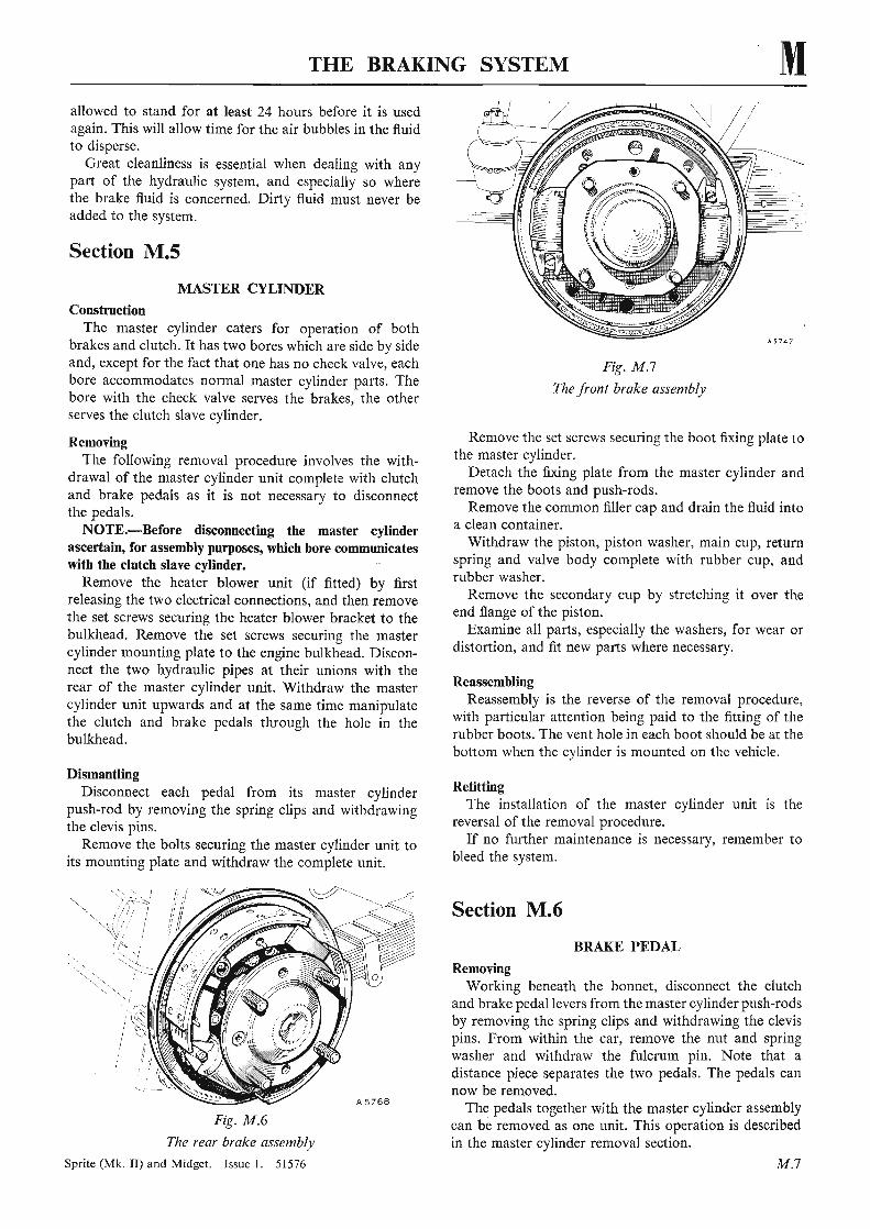
Fig. M .6
The rear brake assembly
Sprite (Mk. II ) and Midget. Issue I. 51576
UU.lA..U ,vU.U . ... """'J.llVY,", 1,..1J,\J .,"' .. .;)\.-l'-'VVl) i)~"'UIJU5 uu::; lliQ.;:)l'li;;l
cylinder mounting plate to the engine bulkhead. Disconnect the two hydraulic pipes at their unions with the
Fig. M.7
The front brake assembly
Remove the set screws securing the boot fixing plate tothe master cylinder.
Detach the fixing plate from the master cylinder andremove the boots and push-rods.
Remove the common filler cap and drain the fluid intoa clean container.
Withdraw the piston, piston washer , main cup, returnspring and valve body complete with rubber cup , andrubber washer.
Remove the secondary cup by stretching it over theend flange of the piston.
Examine all parts, especially the washers, for wear ordistortion, and fit new parts where necessary.
ReassemblingReassembly is the reverse of the removal procedure,
with particular attention being paid to the fitting of therubber boots. The vent hole in each boot should be at thebottom when the cylinder is mounted on the vehicle.
RefittingThe installation of the master cylinder unit is the
reversal of the removal procedure.If no further maintenance is necessary, remember to
bleed the system.
Section M.6
BRAKE PEDAL
RemovingWorking beneath the bonnet, disconnect the clutch
and brake pedal levers from the master cylinder push-rodsby removing the spring clips and withdrawing the clevispins. From within the car, remove the nut and springwasher and withdraw the fulcrum pin. Note that adistance piece separates the two pedals. The pedals cannow be removed.
The pedals together with the master cylinder assemblycan be removed as one unit . This operation is describedin the master cylinder removal section.
M .7
distortion, and 'fit new parts where necessary.

M THE BRAKING SYSTEM
A 9 3 43
Fig. M .8The union nut (1) is the one which must be fi rst unscrewed to release the fl exible hose fro m the pipeline. The attachment nut (2) can then be removed
RefittingWhen refitti ng reverse the remova l procedure.
Section M.7
FRONT BRAKE ASSEMBLIES(Early Cars)
RemovingDisconnect the hydraulic pipe from the master cylinder
at the backplate.Remove the front brake backplate fro m the fro nt
suspension as described in Section K.3 .
DismantlingPull one of the brake-shoes against the load of the
return sp rings, away from the abutment on the closedend of a brake cylinder, and slide the Micram mask offthe pi ston co ver of the operating cylinder; on releasingthe tension of the re turn springs the opposite brake-shoewill fall away.
D isco nnect the bridge pipe between the two brakecylinders complete with the banjo adaptors. Unscre wthe nuts and withdraw the brake cylinders from thebackplate.
To dismantle a brake cylinder withdraw the pi stoncomplete with the pi ston co ver from the cylinder andapply a gentle air pressure to the fluid connection toblowout the rubber cup and cup filler .
ReassemblingClean all components with Lockheed Brake Fl uid and
renew all rubber cups and washers before reassembly.Take care to fit the small end of the coil spring over theprojection in the cup filler.
Reassemble by reversing the dismantling sequence.
M.8
FRONT BRAKE ASSEMBLIES(Early Cars)
RefittingReverse the removal procedure when refitt ing.
Section M.8
REAR BRAKE ASSEMBLIES(Early Cars)
RemovingRemove the wheel , drum, and axle shaft as describ ed
in Section H .3. R em ove the hub assembly (see SectionH A).
Di sconnect the hydraulic pipe fro m the wheel cylinderand the hand brake lever rod, both situated at thebackplate.
Remove the securing nuts and bolts and lift off thebackplat e.
DismantlingPull the t rai ling shoe against the load of the return
springs and away from its abutment a t either end. Onreleasing the tension of the return springs t he leadingshoe will fall away together with the Micram adjuster andmask. Remove the bolt securing the banjo adaptor tothe wheel cylinder and remove the ru bbe r bo ot .
Remove the wheel cylinder piston , swing the handbrake lever until the shoulde r is clea r of the backplate,and slide the cylinder ca stin g forward. Pivot the cylinderabout its fo rward end and withd raw the rear en d fro mthe slot in the backpl ate ; a rearward move ment of thecylinder will no w bring its fo rward end clear of thebackplate.
Withdraw the pi ston complete with cover from thecylinder. Remove the hand brake pivot pin and lever .Apply a gentle air pressure to the fluid connection andblo wout the hydraulic piston, rubber cup, and cup filler.
ReassemblingReassemble by reversing the di smantling procedure,
giving special care to ensure that the slot in the pistoncoincide s with the lever slo t in the cyli nder castin g.
Also ensu re that the M icram adjuste r is in the slotin the leading shoe with the mask in po sition, and thatthe return springs lie between the brake-shoes and thebackplat e. It should be noted that the unlined end of theleading shoe is to be nearest to the brake cylinder ,whilst the unlined en d of the trai ling sho e is to be nearestthe abutment block .
RefittingBefore reversin g the rem oval procedure ensure that
all the adj usters a re backed off.
Section M.9
BRAKE-SHOE RELINING
If it becomes necessary to renew the full set of brakelinings due to excessive wear it is essential to use thesame material as originally specified or of an approved
Sprite (Mk. In and Midget. Issue I. 51576
-backplate.
Withdraw the pi ston co mplete with cove r from the_ . __ _ __ ..J 1 _ _ • _ _

THE BRAKING SYSTEM Malternative, otherwise the present front-to-rear brakebalance will be adversely affected.
Do not reline the brake-shoes with different types oflining.
Any divergence from these stipula tions may give riseto serious consequences due to out-of-balance braki ng.
For information as to approved lining materia ls referto 'GENERAL DATA'.
Owing to the need for the brake linings to be perfectlyconcentric with the brake-drums, special precautionsmust be taken when relining the shoes. It is not recommended that relining be undertaken unless all thespecialist facilities are available. We advise the use ofreplacement shoes, and renewal should be carried out insets to ensure even braking conditions.
After riveting the new linings to the brake-shoes it isessential that any high-spots should be removed beforereplacement on the backplate .
When new linings are fitted considerable adjustmentmust be made to the foot brake mechanism ; turn theadjusters to their fully 'off' position before atte mptingto refit the brake-drums over the new linings. The handbrake must also be in the fully released position.
Do not allow grease or paint to come into contactwith the bra ke linings.
Section M.IO
REMOVING A FLEXIBLE HOSE
Do not attempt to release a flexible hose by turningeither end with a spanner; it should be removed asfollows.
Unscrew the metal pipe line union nut from itsconnection to the hose.
Hold the hexagon on the flexible hose and remove th elocknut securing the flexible hose union to the bracket.
Unscrew the flexible hose from the cylinder.
Section M.II
BRAKE PEDAL CLEARANCE
The correct amount of free movement between themaster cylinder push-rod and piston is set during erectionof the vehicle and should never need alteration.
In the event of the adjustment having been disturbed,reset the effective length of the rod connecting the pistonto the pedal until the pedal pad can be depre ssed approximately -A in. (4 mm.) before the piston begins to move.The clearance can be felt if the pedal is depressed byhand. It is very important that the push-rod should havea minimum free movement of n in. (,8 mm.) before thepiston starts to move.
Section M.12
MAINTENANCE(Later Cars)
Periodically examine the quantity of brake fluid in the
Sprite (Mk. II) and Midget. Issue 1. 51576
either end with a spanner ; it should be removed asfollows.
Fig. M .9
One square-headed brake adjusting bolt is providedon each rear brake-plate
master cylinder. The level should be kept t in. (6-5 mm.)below the bott om of the filler neck, bu t not higher.The necessity for frequent topping up is an indicationof a leak in the system which sho uld at once be tracedand rectified.
Adju st the rear brake-shoes to compensate for wearof the linings. The need for this is shown by the pedalgoing down almost to the floorboards before solidresistance is felt.
In order to maint ain peak braking efficiency and atthe same time obtai n maximum life from the front brakefriction pads they should be exatnined periodically, andif one pad has more wear than the ot her their operatingpositions should be changed over.
IMPORTANT.-Serious consequences may result fromthe use of incorrect fluids. Replenish with LOCKHEEDDISC BRAKE FLUID. Do not use any substitute as thiswill seriously affect the working of the system.
When climatic temperatures are below - 340 C.(-300 F.) the systems should be drained and refilledwith Lockheed Super Heavy Dut y Brake Fluid or a fluidconforming to Specification S.A.E. 70.R3.
LubricationThere is one lubricati ng nipple on the top of the hand
brake compensating lever, and th is is accessible fromunderneath the rear of th e car. Wipe away all the dirtfro m the nipple and give one or two strokes at regularinterva ls with a gun filled with lubricant.
The hand brake cable nipple located ju st forwa rd ofthe rear axle must receive th ree or four strokes at regularintervals with a gun filled with lub ricant.
Section M.13
FRON T BRAKE ASSEMBLIES(Later Cars)
Renewing friction padsJack up the car and remove the road wheel. Depress
the pad retaining spring and withdraw the retaining split
M .9
friction pads they should be exatnined periodically, andif one pad has more wear than the ot her their operating
~i·.._
..+++++..
•..
.._
....
...•.._·H
H......
.._....
.__.
.....~
........
H.__.
_..__
.H_~.
__
.---
."""
""".,
"'""""
,.......,
""""
""""
'".._""'
"'''''''~'''''''"""'
''1I
TH
ER
EA
RB
RA
KE
CO
MP
ON
EN
TS
I3
3
2
32
--
----
.."'"
22
259
I 7
7
BIO
B3
A
i
~j
~+
-++
++
_-+_
......
..-_
__
11
.'1
11
11
11
'.-."
""'.
11
11
11
11
"I
+_III
~II~.'._
._-+__
.......-_
_.-....
...-.
'1"
I11
111-~
II.I
IIII
III++
-+1'•
...,
.~~
+-+-T1
'-~t

C/)
.-.-
....
•._
..-
•••
.-_
,11
••
111
11
11
....
....
-.+
11
11
11
1'
1'
11
111
'II'
"1
1'1
'1"
I'
I'
'I,
111
'1
11
1'
1'1
1'
11
"'I
',
.-.-
'
'0 ::!.
<> ~ ;.;
!" .... .... ., ::I Co
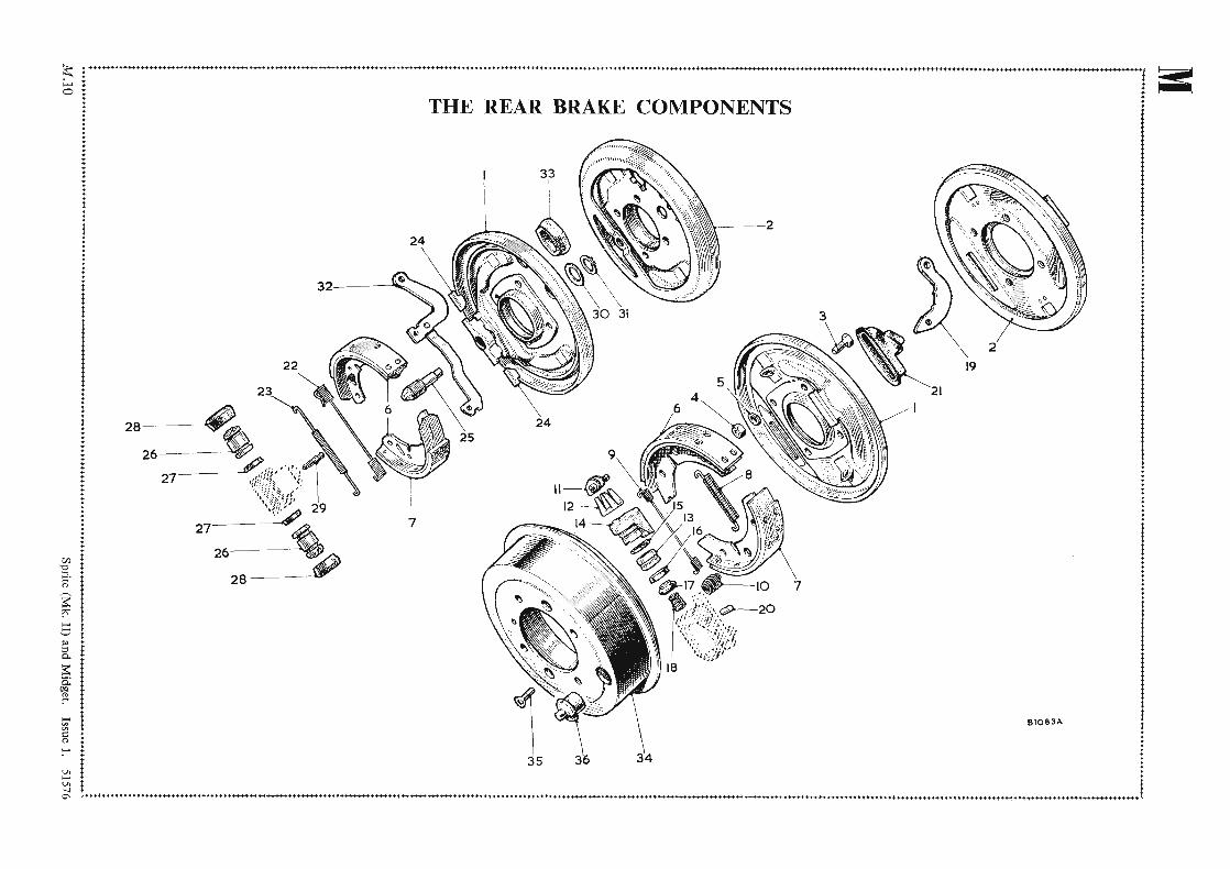
KEY
TOTH
ER
EA
RBR
AK
EC
OM
PO
NE
NT
S
No.
Des
crip
tion
No
.D
escr
ipti
onN
o.D
escr
ipti
on
l.B
rake
-pla
te-R
.H.
13.
Pist
on.
25.
Wed
ge.
2.B
rake
-pla
te-
L.H
.14
.Pi
ston
wit
hdu
stco
ver.
26.
Pist
on.
3.Se
tsc
rew
.IS
.Se
al.
27.
Seal
.
4.N
ut.
16.
Cup
.28
.B
oot.
5.Sp
ring
was
her.
17.
Cup
fille
r.29
.B
leed
ersc
rew
.
6.B
rake
-sho
eas
sem
bly.
18.
Spri
ng.
30.
Bel
levi
llew
ash
er.
7.L
iner
wit
hri
vets
.19
.H
and
brak
ele
ver.
3l.
Cir
clip
.
8.Sh
oere
turn
spri
ng(a
but
men
ten
d).
20.
Pivo
tp
in.
32.
Han
db
rake
leve
r.
9.Sh
oere
turn
spri
ng(c
ylin
der
end)
.21
.B
oot.
33.
Boo
t.
10.
Stea
dy
spri
ng.
22.
Shoe
retu
rnsp
ring
(cyl
inde
ren
d).
34.
Bra
ke-d
rum
.
11.
Adj
uste
ras
sem
bly
.23
.S
hoe
retu
rnsp
ring
(adj
uste
ren
d).
35.
Set
scre
w.
12.
Mas
kad
just
er.
24.
Tap
pet.
36.
Plu
g.
I I I i I I f 1
;l..._..._
.._...._-"",,,,,,
,"".""""",,,,
,,,_,,,,,,,,,,,,,,,
.....
OOIOOO
O"O'O
OIOOOO
IOI_~
++
++
~~.
_+++
+OOOO
oooo,'~
~..
_..~
9.Sh
oere
turn
spri
ng(c
ylin
der
end)
.21
.B
oot.
33.
Boo
t.

M THE BRAKING SYSTEM
Reconnect the brake fluid supply hose and supportthe calliper to avoid straining the hose.
Clamp the piston in the mounting half of the calliperand gently apply the foot brake. This operation willforce the piston in the rim half of the calliper to moveoutwards. Continue with gentle pressure on the footpedal unti l the piston has emerged sufficiently for it to beremoved by hand . Have a clean receptacle ready to catchthe fluid as the piston is removed.
With a suitable blunt-nosed too l remove the fluid sealfrom its groove in the bore of the calliper, taking greatcare not to damage the bore of the calliper or the sealretaining groove.
The dust seal retainer can be removed by inserting ascrewdriver between the retainer and the seal and gentlyprising the retainer from the mouth of the calliper bore.The rubb er seal can then be detached.
Remove the clamp from the mounting-half piston. Toremove the mounting-half piston from the calliper it isnecessary first to refit the rim-half piston, and thereafterthe procedure is as previously detailed.
When cleaning out the calliper it is essential that onlymethylated spirit or the correct Lockheed brake fluid beused as a cleaning medium. Other types of cleaning fluidmay damage the internal rub ber seal between the twohalves of the calliper.
Brake discsFollow the procedure detai led in Section K.6 for the
removal of the brake disc. Should the maximum run-outat the outer periphery of the braking surface exceed·006 in. ('152 mm.) after fitting, the disc must be removedand repositioned on the drive shaft splines.
Rea ssemblingCoat a new fluid seal with Lockheed Disc Brake Lubri
cant, making sure that the seal is absolutely dry before sodoing, and ease the seal into its groove with the fingersuntil it is seating correctly in the groove.
Slacken the bleeder screw in the calliper one completeturn. Coat the piston with Lockheed Disc Brake Lubricant and locate the piston squarely in the mouth of thebore with the cut-away portion of the piston face correctly positioned downwards.
Press in the piston until approximately * in. (8 mm.)of the piston is protruding from the bore. Take great careto prevent the piston tilting during this operation. If thedust seal and retainer have been previously removed,take a new, perfectly dry dust seal, coat it with LockheedDisc Brake Lubricant , and fit the seal into its retainer.Position the seal assembly on the protruding portion ofthe piston with the seal innermost, ensuring that theassembly is square with the piston . Press home the pistonand seal assembly with the clamp . Retighten the bleederscrew.
The moun ting-half piston is dealt with in the samemanner as described for the rim-half piston. The rubberhose must be disconnected to allow the clamp to be usedand the bleeder screw must be slackened .
Sprite (Mks . II and ill) and Midget (Mks . I and 10. Issue 2. 65317
A53B3B10 8
Fig. M .l O
The front brake calliper components1. Fric tion pads. 6. Piston.2. Pad retainin g spring. 7. Bleeder screw.3. Retaining pin. 8. Calliper (mounting half) .4. Piston dust seal. 9. Callipe r (rim half) .5. Piston fluid seal. 10. Calliper mounting point.
11. Anti-squeak shims.
Removing and dismantling a calliperDisconnect the brake fluid supply hose.Remove the nuts securing the hose retaining plate to
the calliper assembly.Unscrew and remove the studs securing the calliper to
the stub axle and withdraw the calliper. Depress the padretaining spring and withdraw the retaining split pins.Remove the friction pad s and anti-squeak shims andclean the outside of the calliper, makin g sure that all dirtand traces of cleaning fluid are completely removed.
M.12
5
pins. Remove the spring and withdraw the friction padsand anti-squeak shims from the calliper, using a slightrotational movement to assist removal. It may benecessary to use a pair of pointed-nose pliers for thisoperation.
Thoroughly clean the exposed face of each piston andensure that the recesses in the calliper which receive thefriction pad assemblies are free from rust and grit. Presseach piston back into the calliper. Whilst this is beingdone the fluid level in the master cylinder will rise, dueto fluid being displaced by the pistons. It may be necessaryto siphon off any surplus from the master cylinder toprevent the fluid from overflowing.
Check that the relieved face of each piston is correctlypositioned and fit the new friction pad assemblies intothe calliper.
Fit the ant i-squeak shims between the piston andfriction pad.
Ensure that the pad assemblies are free to move easilyin the calliper recesses. Remove any high-spots from thepad pressure plate by filing carefully.
Refit the retaining spring in position, press down thespring, and insert the split pins. If the retaining springsshow any signs of damage or loss of tension, new springsmust be fitted.
After fitting new friction pads operate the brake pedalseveral times to adjust the brake. Top up the mastercylinder if necessary.
LV llU I U U lo:'J.lll5 UJ, l:)'p .ia."",,,",u UJ 1.1.1.'-' PJ. ':HVU,;)• .l. L ..lU "")' u \,; U l..lv\.fO,;) U lJ
to siphon off any surp lus from the master cylinder toprevent the fluid from overflowing.
·006 in. ('152 mm.) after fitting, the disc must be removedand repositioned on the drive shaft splines.

THE BRAKING SYSTEM MReconnect the hose and secure the calliper to the stub
axle. Do not depre ss the brake pedal. Fit the frictionpad assemblies, together with their retaining springs andsplit pins , and bleed the system .
After bleeding operate the brake pedal several times toadjust the brake.
Section M.14
REAR BRAKE ASSEMBLIES(Later Cars)
Brake-shoe adjustmentAs the brake linings wear, the pedal will trave l nearer
to the floorboards before the brakes are applied. Whenthe travel becomes excessive the brake-shoes must beadjusted to bring the linings closer to the brake-drum.
One common adjus ter controlling the adjustment ofboth the leading and trailing brake-shoes is located onthe back of each rear brake backplate.
Jack up the car and turn the adjuster screw in a clockwise direction until the brake-drum is locked , thenslacken the screw until the drum rotates without rubbing.
Repeat this adjustment on the othe r rear road wheel.
Removing the rear wheel cylinder assemblyJack up the car, remo ve the road wheel, and thoroughly
clean the brake backplate.Disconnect the flexible fluid supply hose as detai led
in Section M. IO.Unscrew and remo ve the bleed screw. Remove the
circlip from the cylinder boss protruding th rough thebackplate. Remove the brake dru m as described in
Section H. 3. Remove the brake-shoes and extract thecylinder.
Examining the rear wheel cylinder assemblyRemo ve the dust seals from the ends of the cylinder
and extract both pistons. The rubber piston seals shouldbe removed and new seals fitted by using the fingers only.
Do not clean the rubber parts with anything oth er thanthe correct Lockheed brake fluid. All trace s of petrol(gasoline), etc., used for cleaning metal par ts mustbe removed before reassembly.
Refitting the rear wheel cylinder assemblyThe procedure for refitting a rear wheel cylinder is
a reversal of the remo val sequence. In addition, attentionmust be given to bleeding the hydraulic system andadjusting the brake-shoes.
Removing rear shoesChock the front road wheels and set the hand brake
in the 'off' position.Jack up the car and remo ve the road wheel.Remo ve the brake drum as described in Section H .3.Note the position in which the pull-off springs are
fitted and remove the shoes and springs.NOTE.-Do not press the brake pedal with the shoes
removed from the backplate.
Refitting rear shoesRefitting is a reversal of the above procedure; make
sure that the pull-off springs are anchored in their correctholes in the shoe web and th at the brake-shoes registercorrectly in the slotted end of the brake wheel cylinderpiston and in the adjus ter tapp ets.
(For 'SERVICE TOOLS' see page M .14)
Sprite (Mks. II and III) and Midget (Mks. I and II). Issue 2. 65317 M.B
Unscrew and remo ve the bleed screw. Remove thecirclip from the cylinder boss protrudin g th rough the
....... .. - - .t" y o _ - _- ...
holes in the shoe web and that the brake-shoes registercorrectly in the slotted end of the brake wheel cylinder

M THE BRAKING SYSTEM
SERVICE TOOLS
18G 619. Brake Adjusting SpannerThe use of this spanner obviates damage to the
adjusters, enables the brakes to be adjusted more speedilyand effectively, and removes the possibility of damagedknuck les and fingers.
A4767
18G 619
18G 590. Disc Brake Piston Resetting ToolDesigned to reset the pistons when renewing the disc
brake friction pad s, this tool will also be found invaluable, when servicing the callipers, to hold one piston inposition while removing the other piston by means ofhydraulic pressure generat ed in the master cylinder.
M.1 4
18G 590
Sprite (Mks. II and III) and Midget (Mks. I and II). Issue 2. 65317