Section G - Dewatering Strategy.pdf
19
March 2003 Section G – DEWATERING STRATEGY
Transcript of Section G - Dewatering Strategy.pdf

March 2003
Section G – DEWATERING STRATEGY

G-23-1 March 2003
DEWATERING STRATEGY Dewatering refers to the act of removing and discharging water from excavated areas on construction sites or from sediment traps or basins on construction sites. Standards and specifications for dewatering practices follow. These standards apply to removal and discharge of water from any excavated area or sediment trap or basin at any construction site. Given the unique conditions at any particular construction site, any or all of the practices may apply. Regardless of the applicability of the practices listed herein, operators are required to use acceptable procedures for maintenance and dewatering. In all cases, every effort shall be made to eliminate sediment pollution associated with dewatering. Designers shall specify the preferred procedures for dewatering on plans. In particular, designers should identify procedures for dewatering sediment traps and basins prior to elimination of the last sediment control facility on the site or prior to conversion of sediment control facilities to stormwater management facilities. Recommended procedures shall be consistent with these standards. Atypical site conditions may require innovative dewatering designs. Dewatering measures not referenced in this standard may be used with the consent of the approval authority.
Dewatering of Excavated Areas
A. Designers shall specify on plans, and in sequences of construction included on plans, practices for dewatering of excavated areas. Plan reviewers shall check to see that procedures for dewatering are included on plans.
B. In all cases, water removed from excavated areas shall be discharged such that it shall pass through a sediment control device prior to entering receiving waters. Sediment control devices include sediment traps and basins, in addition to the practices in this section.
Approved Practices for Dewatering of Excavated Areas
1. Pumping of water to an existing sediment basin or trap in which the entire volume of water from the area to be dewatered can be contained without discharge to receiving waters.
2. Pumping of water to an existing sediment basin or trap such that the entire volume
of water from the area to be dewatered can be managed without exceeding the design outflow from the sediment control structure.
3. Removable Pumping Station - Standards and specifications for Removable
Pumping Station are on Detail 32A.
G-23-2 March 2003
4. Use of a Sump Pit - Standards and specifications for a sump pit are on Detail 32B.
5. Sediment Tank - Standards and specifications for a sediment tanks are on Details
34 and 35.
Dewatering of Sediment Traps and Basins Designers shall specify on plans, and in sequences of construction included on plans, the practices for dewatering of traps and basins. Plan reviewers shall check to see that procedures for dewatering to be used are included on plans. In all cases, water removed from traps and basins shall be discharged so that it passes through a sediment control device prior to entering receiving waters.
Approved Practices for Dewatering of Traps and Basins
1. Removable pumping station
2. Use of a Sump Pit.
3. Use of a floating suction hose to pump the cleaner water from the top of the pond. As the cleaner water is pumped, the suction hose will lower and eventually encounter sediment laden water. When this happens, the pumping operation will cease. Provisions shall be made to filter water prior to discharge to receiving waters. When floating suction hoses are used, personnel shall be assigned to monitor pumping operations to ensure that sediment pollution is abated.
4. Pumping through an approved geotextile bag.
Pumping sediment laden water into the waters of the District without filtration is strictly forbidden.

G-23-3 March 2003
23.0 DEWATERING SPECIFICATIONS
FOR
REMOVABLE PUMPING STATION
Definition A temporary structure which is used to remove water from excavated areas, sediment traps and basins.
Purpose The Removable Pumping Station is an easily maintained device that filters sediment laden water at a pump intake, prior to discharging to a suitable area.
Conditions Where Practice Applies Removable Pumping Stations are constructed where water collects and must be pumped away during excavation, cofferdam dewatering, maintenance or removal of sediment traps and basins or for other uses as applicable. These are preferred over Sump Pits on projects where a long duration of pumping is expected.
Design Criteria The number of Removable Pumping Stations and their locations shall be determined by the designer and included on the plans. Contractors may relocate sump pits to optimize use but discharge location changes must be coordinated with inspectors. A design is not required but construction must conform to the general criteria outlined on Detail 32A. A perforated, vertical standpipe wrapped with wire mesh and geotextile is placed inside a larger pipe. The outside pipe is then enveloped by a cone of washed stone. Water is then pumped from the center of the inside pipe to a suitable discharge area. Water pumped from the standpipe should discharge into a sediment trap, sediment basin or stabilized area.
Construction Specifications
1. The inner pipe shall be constructed by perforating a 12" to 36" diameter pipe with a watertight cap on the bottom end and wrapping it with 1/2" hardware cloth and
G-23-4 March 2003
Geotextile Class E26. The perforations shall be 1/2" X 6" slits or 1" diameter holes 6" on center.
2. The outer pipe shall be at least 4" larger in diameter than the inside pipe and
wrapped with ½” hardware cloth. Both the inner and outer pipes should extend 12" to 18" above the riser crest elevation, or anticipated high water elevation.
3. Filter material ranging from clean gravel (minimal fines) to #57 stone27 (1 1/2"
maximum diameter) should be backfilled around the outer pipe.
4. The suction hose from the pump shall be placed inside the inner pipe to begin dewatering. The discharge hose shall be placed in a stabilized area downslope of unstabilized areas to prevent erosion. Meadow or wooded areas are preferred discharge locations but storm drains and paved areas are acceptable.
5. Maintenance - The inner pipe can easily be removed to facilitate changing the
geotextile when it clogs. Maintenance must be performed when the pump runs dry and backed up water remains.
Any discharge to sewers needs to be approved by WASA. A permit needs to be obtained.
26 Refer to Table 27 27 Refer to Table 28

G-23-5 March 2003
G-24-1 March 2003
24.0 STANDARDS AND SPECIFICATIONS
FOR
SUMP PIT
Description of Practice A temporary pit from which pumping is conducted to remove excess water while minimizing sedimentation.
Purpose The sump pit filters water being pumped to reduce sedimentation to receiving streams.
Conditions Where Practice Applies Sump Pits are constructed when water collects and must be pumped away during excavating, cofferdam dewatering, maintenance or removal of sediment traps and basins or other uses as applicable.
Design Criteria The number of sump pits and their locations shall be determined by the designer and included on the plans. Contractors may relocate sump pits to optimize use but discharge location changes must be coordinated with inspectors. A design is not required but construction must conform to the general criteria outlined on Detail 32B. A perforated vertical standpipe is wrapped with 1/2" hardware cloth and Geotextile Class E28, then placed in the center of an excavated pit which is then backfilled with filter material consisting of anything from clean gravel (minimal fines) to #57 stone (1 1/2" maximum diameter). Water is then pumped from the center of the standpipe to a suitable discharge area such as into a sediment trap, sediment basin or stabilized area.
Construction Specifications
1. Pit dimensions are variable, with the minimum diameter being twice the diameter of the standpipe.
28 Refer to Table 44 (located on page L-53-1)

G-24-2 March 2003
2. The standpipe should be constructed by perforating a 12" to 36" diameter pipe then wrapping it with 1/2" hardware cloth and Geotextile Class E. The perforations shall be 1/2" X 6" slits or 1" diameter holes 6" on center.
3. A base of filter material consisting of anything from clean gravel (minimal fines)
to #57 stone (1 1/2" maximum diameter) should be placed in the pit to a depth of 12". After installing the standpipe, the pit surrounding the standpipe should then be backfilled with the same filter material.
4. The standpipe shall extend 12" to 18" above the lip of the pit or riser crest
elevation (basin dewatering) and filter material should extend 3" minimum above the anticipated standing water level.
Maintenance To maintain, sump pits must be removed and reconstructed when pump runs dry.

G-24-3 March 2003

G-25-1 March 2003
25.0 STANDARDS AND SPECIFICATIONS
FOR
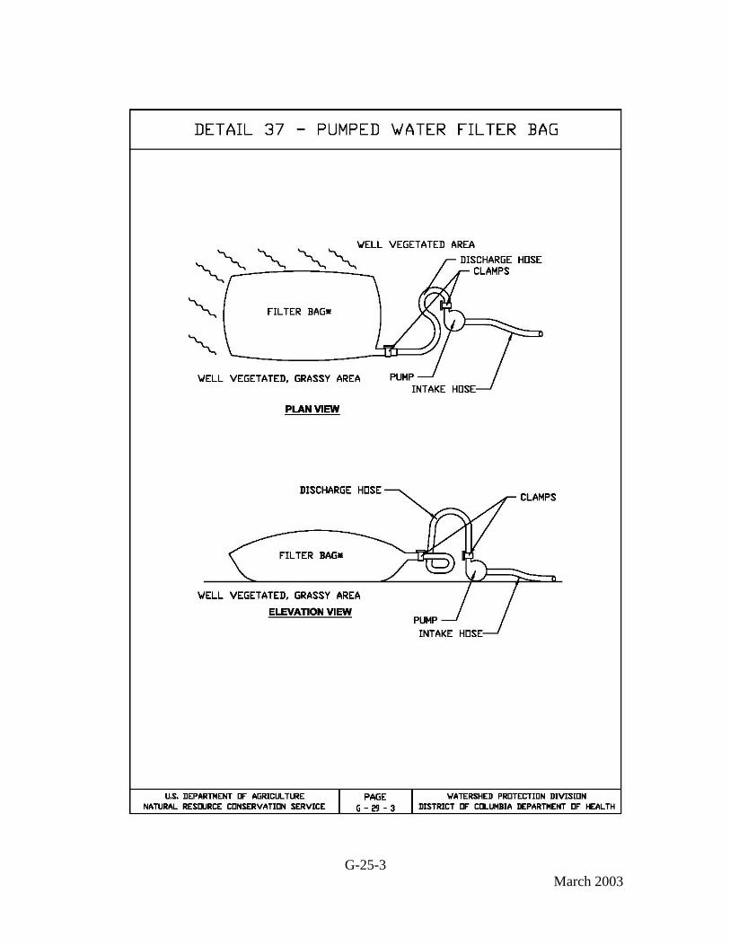
PUMPED WATER FILTER BAGS
Definition A temporary filtering device for water which is discharged from dewatering activities.
Purpose To filter sediment-laden water prior to the water being discharged off-site.
Conditions Where Practice Applies Filter bags may be used to filter water pumped from disturbed areas prior to discharging to waters of the District. They may also be used to filter water pumped from the sediment storage areas of sediment basins.
Design Criteria The pumping rate should be specified on the plan drawings next to the typical detail. Pumping rates will vary depending on the size of the filter bag, and the type and amount of sediment discharged to the bag. Filter bags should be installed according to the details shown in Detail 33. Filter bags shall be made from non-woven geotextile material sewn with high strength, double stitched “J” type seams. They shall be capable of trapping particles larger than 150 microns. A suitable means of accessing the bag with machinery required for disposal purposes must be provided. Filter bags shall be replaced when they become ½ full. Spare bags shall be kept available for replacement of those that have failed or are filled. Bags shall be located in well-vegetated (grassy) area, and discharge onto stable, erosion resistant areas. Where this is not possible, a geotextile flow path shall be provided. Bags shall not be placed on slopes greater than 5%. The pump discharge hose shall be inserted into the bags in the manner specified by the manufacturer and securely clamped.

G-25-2 March 2003
The pumping rate shall be no greater than 750 gpm or ½ the maximum specified by the manufacturer, whichever is less. Pump intakes should be floating and screened. Filter bags shall be inspected daily. If any problem is detected, pumping shall cease immediately and not resume until the problem is corrected.
G-25-3 March 2003

G-26-1 March 2003
26.0 STANDARDS AND SPECIFICATIONS
FOR
SEDIMENT TANKS
Definition A sediment tank is a compartmented tank container through which sediment laden water is pumped to trap and retain the sediment.
Purpose To trap and retain sediment prior to pumping the water to drainage ways, adjoining properties, and rights-of-way below the sediment tank site.
Conditions Where Practice Applies A sediment tank is to be used on sites where excavations are deep, and space is limited, such as urban construction, where direct discharge of sediment laden water to stream and storm drainage systems is to be avoided.
Design Criteria
1. A sediment tank must be sized (and operated) to allow pumped water to flow through the filtering device without overtopping the structure.
2. Material from any required excavation shall be stored in an area and protected in a
manner that will prevent sediments from eroding and moving off-site.
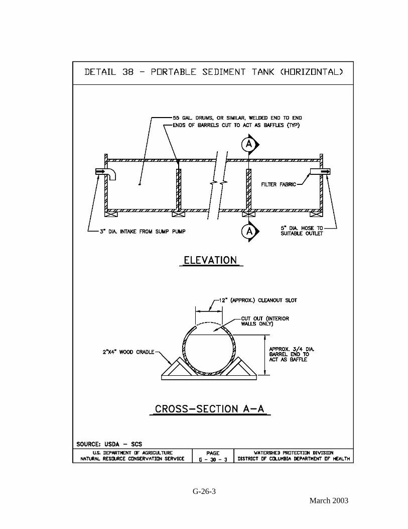
Construction Specifications
1. Portable Sediment Tank - Horizontal (see Detail 34)
a. The structure may be constructed with steel drums, sturdy wood or other material suitable for handling the pressure exerted by the volume of water.
b. Sediment tanks will have a minimum depth of two feet
c. The sediment tank shall be located for easy clean-out and disposal of the
trapped sediment and to minimize the interference with construction activities.

G-26-2 March 2003
d. The following formula shall be used to determine the storage volume of
the sediment tank:
Pump discharge (g.p.m.) x 16 = cubic feet of storage required
e. Once the water level nears the top of the tank, the pump must be shut off while the tank drains and additional capacity is made available.
f. The tank shall be designed to allow for emergency flow over top of the
tank.
g. Clean-out of the tank is required once one-third of the original capacity is depleted due to sediment accumulation. The tank shall be clearly marked showing the clean-out point.
2. Portable Sediment Tank - Vertical (see Detail 35)
a. Location The sediment tank shall be located for ease of clean-out and disposal of the trapped sediment and to minimize interference with construction activities and pedestrian traffic.
b. Tank Size The following formula should be used in determining the
storage volume of the sediment tank: 1 cubic foot of storage for each gallon per minute of pump discharge capacity.
c. Tanks may be connected in series. Geotextile fabric mesh sizes may vary
from tank to tank with the downstream-most layer meeting Geotextile Class SE29 or better.
Maintenance (All sediment tanks)
1. The filtering devices must be inspected frequently and repaired or replaced once the sediment build-up prevents the structure from functioning as designed.
2. The accumulated sediment which is removed from a dewatering device must be
spread on-site and stabilized or disposed of at an approved disposal site as per approved plan.
29 Refer to Table 44 (located on page L-53-1)
G-26-3 March 2003

G-26-4 March 2003

G-27-1 March 2003
27.0 STANDARDS AND SPECIFICATIONS
FOR
DEWATERING BASINS
Definition Temporary measure for filtering sediment-laden water
Description
The work should consist of installing dewatering basins jointly with channel diversion measures to filter sediment laden water from in-stream construction sites before the water re-enters the downstream reach. This practice may also be used for work outside of streams.
Effective Uses & Limitations Undersized dewatering basins will not adequately filter sediment-laden water from the construction site.
Material Specifications Materials for dewatering basins should meet the following requirements:
• Riprap: Riprap should be washed and have a diameter ranging from 4 to 6 inches (10 to 15 centimeters).
Design Criteria 1 Measure shall consist of straw bales, silt fence, a stone outlet and a wet storage pit
oriented as shown in Detail 36. 2. The structure must have a capacity which is dictated by the following formula:
Pump discharge (g.p.m.) x 16 = cubic feet of storage required
In calculating the capacity, one should include the volume available from the floor of the excavation to the crest of the stone weir.
3. In any case, the excavated area should be a minimum of 3 feet below the base of
the perimeter measures (straw bales or silt fence).

G-27-2 March 2003
4. The perimeter measures must be installed as per the guidelines found in 4.0 Straw Bale Dike and 5.0 Silt Fence.
5. Once the water level nears the crest of the stone weir (emergency overflow), the
pump must be shut off while the structure drains down to the elevation of the wet storage.
6. The wet storage pit may be dewatered only after a minimum of 6 hours of
sediment settling time. This effluent should be pumped across a well-vegetated area or through a silt fence prior to entering a watercourse.
7. Once the wet storage area becomes filled to one-half of the excavated depth,
accumulated sediment shall be removed and properly disposed of. 8. Once the device has been removed, ground contours will be returned to original
condition. 9. Riprap should be washed and have a diameter ranging from 4 to 6 inches. 10. The dewatering basin must be sized (and operated) to allow pumped water to flow
through the filtering device without overtopping the structure. 11. Material from any required excavation shall be stored in an area and protected in a
manner that will prevent sediments from eroding and moving off-site. 12. An excavated basin may be lined with filter fabric to help reduce scour and to
prevent the inclusion of soil from within the structure.
Maintenance Dewatering basins must be inspected frequently and repaired or replaced once the sediment build-up prevents the structure from functioning as designed.
The accumulated sediment which is removed from a dewatering device must be spread on-site and stabilized or disposed of at an approved disposal site as per approved plan.

G-27-3 March 2003