SECTION CONCRETE STRUCTURES CALIFORNIA AMENDMENTS … · SECTION 5: CONCRETE STRUCTURES CALIFORNIA...
82
SECTION 5: CONCRETE STRUCTURES CALIFORNIA AMENDMENTS TO AASHTO LRFD BRIDGE DESIGN SPECIFICATIONS – 8 TH EDITION 5-9A April 2019 5.3—NOTATION Replace the following notation: fcpe = compressive stress in concrete due to effective prestress forces only (after allowance for all prestress losses), not including the effects of secondary moment, at extreme fiber of section where tensile stress is caused by externally applied loads (ksi) (5.6.3.3)
Transcript of SECTION CONCRETE STRUCTURES CALIFORNIA AMENDMENTS … · SECTION 5: CONCRETE STRUCTURES CALIFORNIA...

SECTION 5: CONCRETE STRUCTURES CALIFORNIA AMENDMENTS TO AASHTO LRFD BRIDGE DESIGN SPECIFICATIONS – 8TH EDITION 5-9A
April 2019
5.3—NOTATION
Replace the following notation:
fcpe = compressive stress in concrete due to effective prestress forces only (after allowance for all prestress losses), not including the effects of secondary moment, at extreme fiber of section where tensile stress is caused by externally applied loads (ksi) (5.6.3.3)

SECTION 5: CONCRETE STRUCTURES CALIFORNIA AMENDMENTS TO AASHTO LRFD BRIDGE DESIGN SPECIFICATIONS – 8TH EDITION 5-9B
April 2019
This page intentionally left blank.

SECTION 5: CONCRETE STRUCTURES CALIFORNIA AMENDMENTS TO AASHTO LRFD BRIDGE DESIGN SPECIFICATIONS – 8TH EDITION 5-15A
April 2019
5.4.2.1—Compressive Strength
Replace the 3rd paragraph with the following:
The design concrete compressive strength for prestressed concrete and decks shall not be less than 4.0 ksi. The design concrete compressive strength shall not be less than 3.6 ksi for all other reinforced concrete.

SECTION 5: CONCRETE STRUCTURES CALIFORNIA AMENDMENTS TO AASHTO LRFD BRIDGE DESIGN SPECIFICATIONS – 8TH EDITION 5-15B
April 2019
This page intentionally left blank.
SECTION 5: CONCRETE STRUCTURES CALIFORNIA AMENDMENTS TO AASHTO LRFD BRIDGE DESIGN SPECIFICATIONS – 8TH EDITION 5-22A
April 2019
5.4.4—Prestressing Steel
5.4.4.1 General
Add a new 2nd paragraph as follows:
ASTM A722 bars shall not be galvanized. No cleaning process shall be used that will introduce hydrogen into steel.
C5.4.4.1
Add a new paragraph as follows:
Galvanization of ASTM A722 bars is not permitted due to hydrogen embrittlement.

SECTION 5: CONCRETE STRUCTURES CALIFORNIA AMENDMENTS TO AASHTO LRFD BRIDGE DESIGN SPECIFICATIONS – 8TH EDITION 5-22B
April 2019
This page intentionally left blank.
SECTION 5: CONCRETE STRUCTURES CALIFORNIA AMENDMENTS TO AASHTO LRFD BRIDGE DESIGN SPECIFICATIONS – 8TH EDITION 5-24A
April 2019
5.4.6.2—Size of Ducts
Replace the 2nd paragraph with the following:
The size of ducts in cast-in-place concrete shall not exceed 0.5 times the least gross concrete thickness at the duct.

SECTION 5: CONCRETE STRUCTURES CALIFORNIA AMENDMENTS TO AASHTO LRFD BRIDGE DESIGN SPECIFICATIONS – 8TH EDITION 5-24B
April 2019
This page intentionally left blank.
SECTION 5: CONCRETE STRUCTURES CALIFORNIA AMENDMENTS TO AASHTO LRFD BRIDGE DESIGN SPECIFICATIONS – 8TH EDITION 5-26A
April 2019
5.5.3—Fatigue Limit State
5.5.3.1—General
Replace the 1st paragraph with the following:
Fatigue need not be investigated for concrete deck slabs in multigirder applications, approach slabs, slab bridges, or reinforced-concrete box culverts.
C5.5.3.1
Replace the 3rd paragraph with the following:
In determining the need to investigate fatigue, Table 3.4.1-1 specifies a load factor of 1.75 on the live load force effect resulting from the fatigue truck for the Fatigue I load combination. This factored live load force effect represents the greatest fatigue stress that the bridge will experience during its life.

SECTION 5: CONCRETE STRUCTURES CALIFORNIA AMENDMENTS TO AASHTO LRFD BRIDGE DESIGN SPECIFICATIONS – 8TH EDITION 5-26B
April 2019
This page intentionally left blank.

SECTION 5: CONCRETE STRUCTURES CALIFORNIA AMENDMENTS TO AASHTO LRFD BRIDGE DESIGN SPECIFICATIONS – 8TH EDITION 5-28A
April 2019
5.5.3.4—Welded or Mechanical Splices of Reinforcement
Replace the 1st paragraph with the following:
For welded or mechanical connections that are subject to repetitive loads, the constant-amplitude fatigue threshold, (ΔF)TH, shall be as given in Table 5.5.3.4-1. Both the Fatigue I load combination for infinite fatigue life, and the Fatigue II load combination for finite fatigue life specified in Table 3.4.1-1 shall be evaluated.

SECTION 5: CONCRETE STRUCTURES CALIFORNIA AMENDMENTS TO AASHTO LRFD BRIDGE DESIGN SPECIFICATIONS – 8TH EDITION 5-28B
April 2019
This page intentionally left blank.

SECTION 5: CONCRETE STRUCTURES CALIFORNIA AMENDMENTS TO AASHTO LRFD BRIDGE DESIGN SPECIFICATIONS – 8TH EDITION 5-29A
April 2019
5.5.4.2—Resistance Factors
Replace the 2nd bullet in the 2nd paragraph with the following:
For tension-controlled precast prestressed concrete sections with bonded strands or tendons as specified in Article 5.6.2.1:
normal weight concrete .......... 1.00 lightweight concrete ............... 1.00
Add the following bullet under the 2nd bullet in the 2nd paragraph:
For tension-controlled cast-in-place post-tensioned concrete sections or post-tensioned spliced precast concrete sections with bonded strands or tendons as defined in Article 5.6.2.1:
normal weight concrete .......... 0.95 lightweight concrete ............... 0.95
SECTION 5: CONCRETE STRUCTURES CALIFORNIA AMENDMENTS TO AASHTO LRFD BRIDGE DESIGN SPECIFICATIONS – 8TH EDITION 5-30A
April 2019
C5.5.4.2
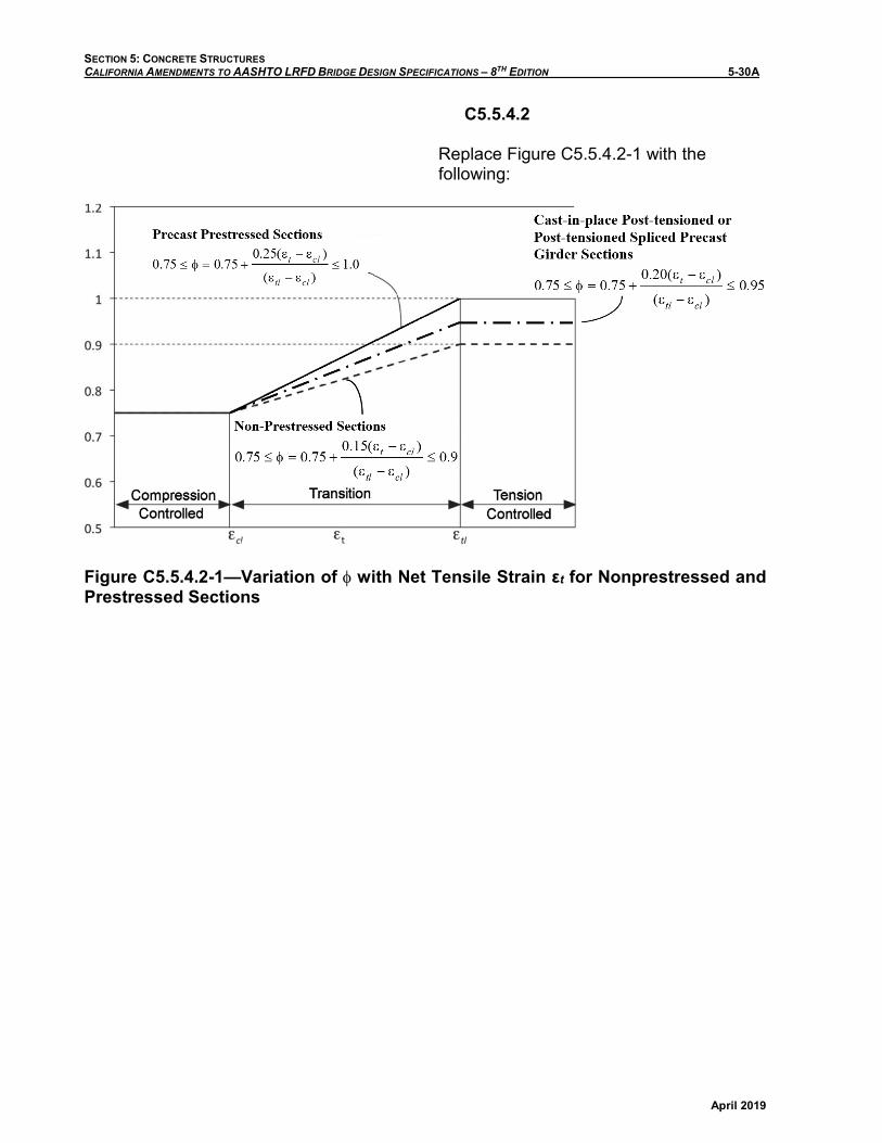
Replace Figure C5.5.4.2-1 with the following:
Figure C5.5.4.2-1—Variation of φ with Net Tensile Strain εt for Nonprestressed and Prestressed Sections

SECTION 5: CONCRETE STRUCTURES CALIFORNIA AMENDMENTS TO AASHTO LRFD BRIDGE DESIGN SPECIFICATIONS – 8TH EDITION 5-31A
April 2019
Replace the 4th paragraph of the article with the following:
This variation ϕ may be computed such that:
For precast prestressed concrete sections:
0.75 ≤ ϕ = 0.75 + 0.25(εt - εcl)(εtl - εcl)
≤ 1.0 (5.5.4.2-1)
For cast-in-place post-tensioned or post-tensioned spliced precast concrete sections:
0.75 ≤ ϕ = 0.75 + 0.20(εt - εcl)(εtl - εcl)
≤ 0.95 (5.5.4.2-1a)
and for nonprestressed concrete sections such that:
0.75 ≤ ϕ = 0.75 + 0.15(εt - εcl)(εtl - εcl)
≤ 0.9 (5.5.4.2-2)
where:
εt = net tensile strain in the extreme tensionsteel at nominal resistance (in./in.)
εcl = compression-controlled strain limit in the extreme tension steel (in./in.)
εtl = tension-controlled strain limit in the extreme tension steel (in./in.)

SECTION 5: CONCRETE STRUCTURES CALIFORNIA AMENDMENTS TO AASHTO LRFD BRIDGE DESIGN SPECIFICATIONS – 8TH EDITION 5-31B
April 2019
This page intentionally left blank.
SECTION 5: CONCRETE STRUCTURES CALIFORNIA AMENDMENTS TO AASHTO LRFD BRIDGE DESIGN SPECIFICATIONS – 8TH EDITION 5-32A
April 2019
5.5.5—Extreme Event Limit State
5.5.5.1—General
Replace the 1st paragraph with the following:
The structure as a whole and its components shall be proportioned to resist collapse due to extreme events, specified in Table 3.4.1-1, as may be appropriate to its site and use. Resistance factors shall be 1.0.

SECTION 5: CONCRETE STRUCTURES CALIFORNIA AMENDMENTS TO AASHTO LRFD BRIDGE DESIGN SPECIFICATIONS – 8TH EDITION 5-32B
April 2019
This page intentionally left blank.
SECTION 5: CONCRETE STRUCTURES CALIFORNIA AMENDMENTS TO AASHTO LRFD BRIDGE DESIGN SPECIFICATIONS – 8TH EDITION 5-34A
April 2019
5.6.2.1—General
Replace the 11th bullet with the following:
• Sections are tension-controlled where the net tensile stain in the extreme tension steel is equal to or greater than the tension-controlled strain limit, εtl just as the concrete in compression reaches its assumed strain limit of 0.003. Sections with net tensile strain in the extreme tension steel between the compression-controlled strain limit and the tension-controlled strain limit constitute a transition region between compression controlled and tension-controlled sections. For nonprestressed concrete members with factored axial compressive load less than 0.1f’cAg, the net tensile strain in the extreme tension steel at a section shall not be less than 0.004 just as the concrete in compression reaches its assumed strain limit of 0.003. The tension-controlled strain limit, εtl , shall be taken as 0.005 for nonprestressed reinforcement with a specified minimum yield strength, fy = 100 ksi. For nonprestressed reinforcement with a specified minimum yield strength between 75.0 and 100 ksi, the tension-controlled strain limit shall be determined by linear interpolation based on specified minimum yield strength.
C5.6.2.1
Replace the 5th paragraph with the following:
Where the net tensile strain in the extreme tension steel is sufficiently large (equal to or greater than the tension-controlled strain limit), the section is defined as tension-controlled where ample warning of failure with excessive deflection and cracking may be expected. Where the net tensile strain in the extreme tension steel is small (less than or equal to the compression-controlled strain limit), a brittle failure condition may be expected, with little warning of impending failure. Flexural members are usually tension-controlled, while compression members are usually compression-controlled. Members with a factored axial compressive load that is less than 0.1f’cAg can be regarded as flexural members. Some sections, such as those with small axial load and large bending moment, will have net tensile strain in the extreme tension steel between the above limits. These sections are in a transition region between compression- and tension-controlled sections. Article 5.5.4.2 specifies the appropriate resistance factors for tension-controlled and compression-controlled sections, and for intermediate cases in the transition region.

SECTION 5: CONCRETE STRUCTURES CALIFORNIA AMENDMENTS TO AASHTO LRFD BRIDGE DESIGN SPECIFICATIONS – 8TH EDITION 5-34B
April 2019
This page intentionally left blank.

SECTION 5: CONCRETE STRUCTURES CALIFORNIA AMENDMENTS TO AASHTO LRFD BRIDGE DESIGN SPECIFICATIONS – 8TH EDITION 5-41A
April 2019
5.6.3.3—Minimum Reinforcement
Replace the following notation:
fcp = compressive stress in concrete due to effective prestress forces only (after allowance for all prestress losses), not including the effects of secondary moment, at extreme fiber of section where tensile stress is caused by externally applied loads (ksi)

SECTION 5: CONCRETE STRUCTURES CALIFORNIA AMENDMENTS TO AASHTO LRFD BRIDGE DESIGN SPECIFICATIONS – 8TH EDITION 5-41B
April 2019
This page intentionally left blank.
SECTION 5: CONCRETE STRUCTURES CALIFORNIA AMENDMENTS TO AASHTO LRFD BRIDGE DESIGN SPECIFICATIONS – 8TH EDITION 5-43A
April 2019
5.6.3.5.2—Deflection and Camber
Replace the 1st paragraph with the following:
Deflection and camber calculations shall consider the appropriate combinations of dead load, live load, prestressing forces, erection loads, concrete creep and shrinkage, and steel relaxation.
Add a new paragraph after the 1st paragraph:
Long-term deflection calculations to estimate camber shall consider deflections due to appropriate combinations of all of the above mentioned load effects except for those due to live load.
C5.6.3.5.2
Replace the 1st paragraph with the following:
Camber is the deflection that is built into a member, other than by prestressing, in order to achieve the desired roadway geometry.
Add a new paragraph after the 1st paragraph:
Past experience with cast-in-place box girder bridges show that the design predictions of camber based on Ig are generally in conformance with field measured values.
SECTION 5: CONCRETE STRUCTURES CALIFORNIA AMENDMENTS TO AASHTO LRFD BRIDGE DESIGN SPECIFICATIONS – 8TH EDITION 5-44A
April 2019
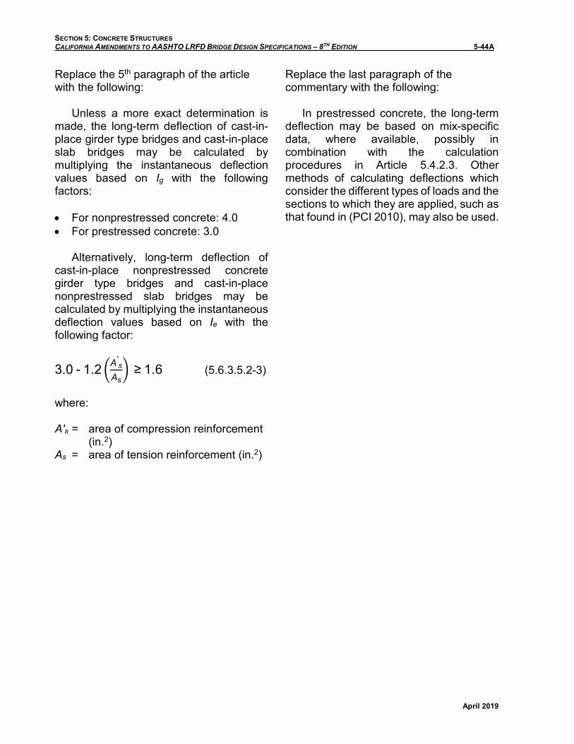
Replace the 5th paragraph of the article with the following:
Unless a more exact determination is made, the long-term deflection of cast-in-place girder type bridges and cast-in-place slab bridges may be calculated by multiplying the instantaneous deflection values based on Ig with the following factors:
• For nonprestressed concrete: 4.0 • For prestressed concrete: 3.0
Alternatively, long-term deflection of cast-in-place nonprestressed concrete girder type bridges and cast-in-place nonprestressed slab bridges may be calculated by multiplying the instantaneous deflection values based on Ie with the following factor:
3.0 - 1.2 �A's
As� ≥ 1.6 (5.6.3.5.2-3)
where:
A′s = area of compression reinforcement (in.2)
As = area of tension reinforcement (in.2)
Replace the last paragraph of the commentary with the following:
In prestressed concrete, the long-term deflection may be based on mix-specific data, where available, possibly in combination with the calculation procedures in Article 5.4.2.3. Other methods of calculating deflections which consider the different types of loads and the sections to which they are applied, such as that found in (PCI 2010), may also be used.
SECTION 5: CONCRETE STRUCTURES CALIFORNIA AMENDMENTS TO AASHTO LRFD BRIDGE DESIGN SPECIFICATIONS – 8TH EDITION 5-55A
April 2019
5.6.7—Control of Cracking by Distribution of Reinforcement
Replace the 3rd paragraph with the following:
Class 1 exposure condition applies when cracks can be tolerated due to reduced concerns of appearance, corrosion, or both. Class 2 exposure condition applies when there is increased concern of appearance, corrosion, or both.
Add a new paragraph after the 3rd paragraph:
Class 2 exposure condition applies to all bridge decks. The clear concrete cover to the top reinforcement shall be taken as 2 ½ in. to determine dc for use in Eq. 5.6.7-1 when verifying reinforcement spacing in bridge decks.

SECTION 5: CONCRETE STRUCTURES CALIFORNIA AMENDMENTS TO AASHTO LRFD BRIDGE DESIGN SPECIFICATIONS – 8TH EDITION 5-55B
April 2019
This page intentionally left blank.
SECTION 5: CONCRETE STRUCTURES CALIFORNIA AMENDMENTS TO AASHTO LRFD BRIDGE DESIGN SPECIFICATIONS – 8TH EDITION 5-58A
April 2019
5.7.2—General Requirements
5.7.2.1—General
Replace the 8th paragraph with the following:
The factored shear resistance, Vr, shall be taken as:
Vr = ϕVn (5.7.2.1-1)
And the factored shear, Vu, shall be less than or equal to the factored shear resistance, Vr.
Vu ≤ Vr (5.7.2.1-1a)

SECTION 5: CONCRETE STRUCTURES CALIFORNIA AMENDMENTS TO AASHTO LRFD BRIDGE DESIGN SPECIFICATIONS – 8TH EDITION 5-58B
April 2019
This page intentionally left blank.
SECTION 5: CONCRETE STRUCTURES CALIFORNIA AMENDMENTS TO AASHTO LRFD BRIDGE DESIGN SPECIFICATIONS – 8TH EDITION 5-60A
April 2019
C5.7.2.1
Replace the last paragraph with the following:
In determining the effective web width, be, at a particular level, one-half the diameters of ungrouted ducts up to a maximum of 2 in. or one-quarter the diameter of grouted ducts up to a maximum of 1 in. at that level shall be subtracted from the web width for spliced precast girders. It is not necessary to reduce the effective web width for the presence of ducts in fully grouted cast-in-place box girder frames.

SECTION 5: CONCRETE STRUCTURES CALIFORNIA AMENDMENTS TO AASHTO LRFD BRIDGE DESIGN SPECIFICATIONS – 8TH EDITION 5-60B
April 2019
This page intentionally left blank.
SECTION 5: CONCRETE STRUCTURES CALIFORNIA AMENDMENTS TO AASHTO LRFD BRIDGE DESIGN SPECIFICATIONS – 8TH EDITION 5-62A
April 2019
5.7.2.6—Maximum Spacing of Transverse Reinforcement
Replace the 1st bullet in the 1st paragraph with the following:
• If vu < 0.125 f ′c, then: Smax = 0.8dv ≤ 18.0in. (5.7.2.6-1)
C5.7.2.6
Add a new paragraph before the 1st paragraph:
The maximum spacing of the girder shear reinforcement that extends into a cast-in-place concrete deck should be limited to 18 in. based on the recommendations in the report “I-40 Bridge Investigation Final Report” prepared by Wiss, Janney, Elstner Associates, Inc., Nov, 2007.

SECTION 5: CONCRETE STRUCTURES CALIFORNIA AMENDMENTS TO AASHTO LRFD BRIDGE DESIGN SPECIFICATIONS – 8TH EDITION 5-62B
April 2019
This page intentionally left blank.

SECTION 5: CONCRETE STRUCTURES CALIFORNIA AMENDMENTS TO AASHTO LRFD BRIDGE DESIGN SPECIFICATIONS – 8TH EDITION 5-68A
April 2019
5.7.3.4—Procedures for Determining Shear Resistance Parameters β and θ
C5.7.3.4
Replace the commentary with the following:
Two complementary methods are given for evaluating shear resistance. Method 1, specified in Article 5.7.3.4.1, as described herein, is only applicable for nonprestressed sections. Method 2, as described in Article 5.7.3.4.2, is applicable for all prestressed and nonprestressed members, with and without shear reinforcement, with and without axial load. In Method 2, an evaluation using tabularized values presented in Appendix B5 is adopted.

SECTION 5: CONCRETE STRUCTURES CALIFORNIA AMENDMENTS TO AASHTO LRFD BRIDGE DESIGN SPECIFICATIONS – 8TH EDITION 5-68B
April 2019
This page intentionally left blank.
SECTION 5: CONCRETE STRUCTURES CALIFORNIA AMENDMENTS TO AASHTO LRFD BRIDGE DESIGN SPECIFICATIONS – 8TH EDITION 5-69A
April 2019
5.7.3.4.2—General Procedure
Replace the entire article with the following:
The General Procedure for Shear Design with Tables, as described in the provisions of Appendix B5, shall be used.
C5.7.3.4.2
Delete the entire commentary.

SECTION 5: CONCRETE STRUCTURES CALIFORNIA AMENDMENTS TO AASHTO LRFD BRIDGE DESIGN SPECIFICATIONS – 8TH EDITION 5-69B
April 2019
This page intentionally left blank.
SECTION 5: CONCRETE STRUCTURES CALIFORNIA AMENDMENTS TO AASHTO LRFD BRIDGE DESIGN SPECIFICATIONS – 8TH EDITION 5-73A
April 2019
5.7.3.5—Longitudinal Reinforcement C5.7.3.5
Add a new paragraph after the 1st paragraph as follows:
When using Eq. 5.7.3.5-1, conservatively, non-concurrent values for Mu and Vu may be used to evaluate longitudinal reinforcement. When coincident values are used, both maximum Mu with coincident Vu, and maximum Vu with coincident Mu, should be checked. If approximate methods are used for the distribution of live loads, the girder distribution factor for bending should be used for both maximum MLL and coincident MLL, and the girder distribution factor for shear should be used for both maximum VLL and coincident VLL. For Strength I, force effects due to both the typical and contraflexure truck configurations should be evaluated.

SECTION 5: CONCRETE STRUCTURES CALIFORNIA AMENDMENTS TO AASHTO LRFD BRIDGE DESIGN SPECIFICATIONS – 8TH EDITION 5-73B
April 2019
This page intentionally left blank.

SECTION 5: CONCRETE STRUCTURES CALIFORNIA AMENDMENTS TO AASHTO LRFD BRIDGE DESIGN SPECIFICATIONS – 8TH EDITION 5-82A
April 2019
5.7.4.5—Computation of the Factored Interface Shear Force for Girder/Slab Bridges
Replace the last paragraph with the following:
For beams or girders, the longitudinal center-to-center spacing of non-welded interface shear connectors shall not exceed 48.0 in. or the depth of the member, h. For cast-in-place box girders, the longitudinal center-to-center spacing of non-welded interface shear connectors shall not exceed 18.0 in.

SECTION 5: CONCRETE STRUCTURES CALIFORNIA AMENDMENTS TO AASHTO LRFD BRIDGE DESIGN SPECIFICATIONS – 8TH EDITION 5-82B
April 2019
This page intentionally left blank.
SECTION 5: CONCRETE STRUCTURES CALIFORNIA AMENDMENTS TO AASHTO LRFD BRIDGE DESIGN SPECIFICATIONS – 8TH EDITION 5-101A
April 2019
5.8.4.1—Deep Components
Replace the article with the following:
Although the strut-and-tie method of Article 5.8.2 is the preferred method for designing deep components, legacy methods that have served an owner well may be used provided that all of the following are met:
• The provisions of Article 5.8.2.6 specifying the amount and spacing of crack control reinforcement are met as a minimum, except that the spacing of the crack control bars shall not exceed 24 in.;
• A limit on usable shear capacity is specified;
• The loading is placed at the appropriate depth of the component relative to the reactions in a manner consistent with the legacy method being used;
• The method of analysis reflects the distributed stress field, the behavior of cracked concrete and other nonlinear behavior anticipated at the strength or extreme event limit state.
C5.8.4.1
Add the following paragraph at the end of the commentary:
Legacy methods shall only be used for conventional geometries and loading applications.

SECTION 5: CONCRETE STRUCTURES CALIFORNIA AMENDMENTS TO AASHTO LRFD BRIDGE DESIGN SPECIFICATIONS – 8TH EDITION 5-101B
April 2019
This page intentionally left blank.
SECTION 5: CONCRETE STRUCTURES CALIFORNIA AMENDMENTS TO AASHTO LRFD BRIDGE DESIGN SPECIFICATIONS – 8TH EDITION 5-121A
April 2019
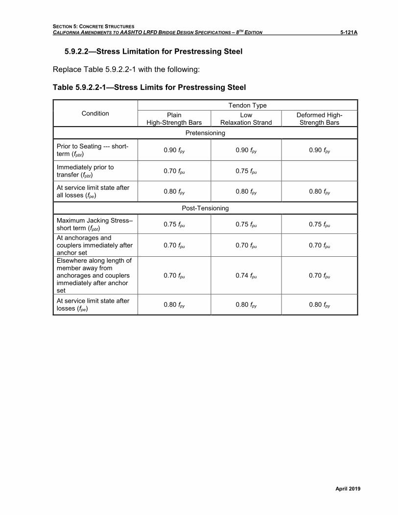
5.9.2.2—Stress Limitation for Prestressing Steel
Replace Table 5.9.2.2-1 with the following:
Table 5.9.2.2-1—Stress Limits for Prestressing Steel
Condition Tendon Type
Plain High-Strength Bars
Low Relaxation Strand
Deformed High-Strength Bars
Pretensioning
Prior to Seating --- short-term (fpbt) 0.90 fpy 0.90 fpy 0.90 fpy
Immediately prior to transfer (fpbt) 0.70 fpu 0.75 fpu
At service limit state after all losses (fpe) 0.80 fpy 0.80 fpy 0.80 fpy
Post-Tensioning
Maximum Jacking Stress–short term (fpbt) 0.75 fpu 0.75 fpu 0.75 fpu
At anchorages and couplers immediately after anchor set
0.70 fpu 0.70 fpu 0.70 fpu
Elsewhere along length of member away from anchorages and couplers immediately after anchor set
0.70 fpu 0.74 fpu 0.70 fpu
At service limit state after losses (fpe) 0.80 fpy 0.80 fpy 0.80 fpy

SECTION 5: CONCRETE STRUCTURES CALIFORNIA AMENDMENTS TO AASHTO LRFD BRIDGE DESIGN SPECIFICATIONS – 8TH EDITION 5-121B
April 2019
This page intentionally left blank.
SECTION 5: CONCRETE STRUCTURES CALIFORNIA AMENDMENTS TO AASHTO LRFD BRIDGE DESIGN SPECIFICATIONS – 8TH EDITION 5-125A
April 2019
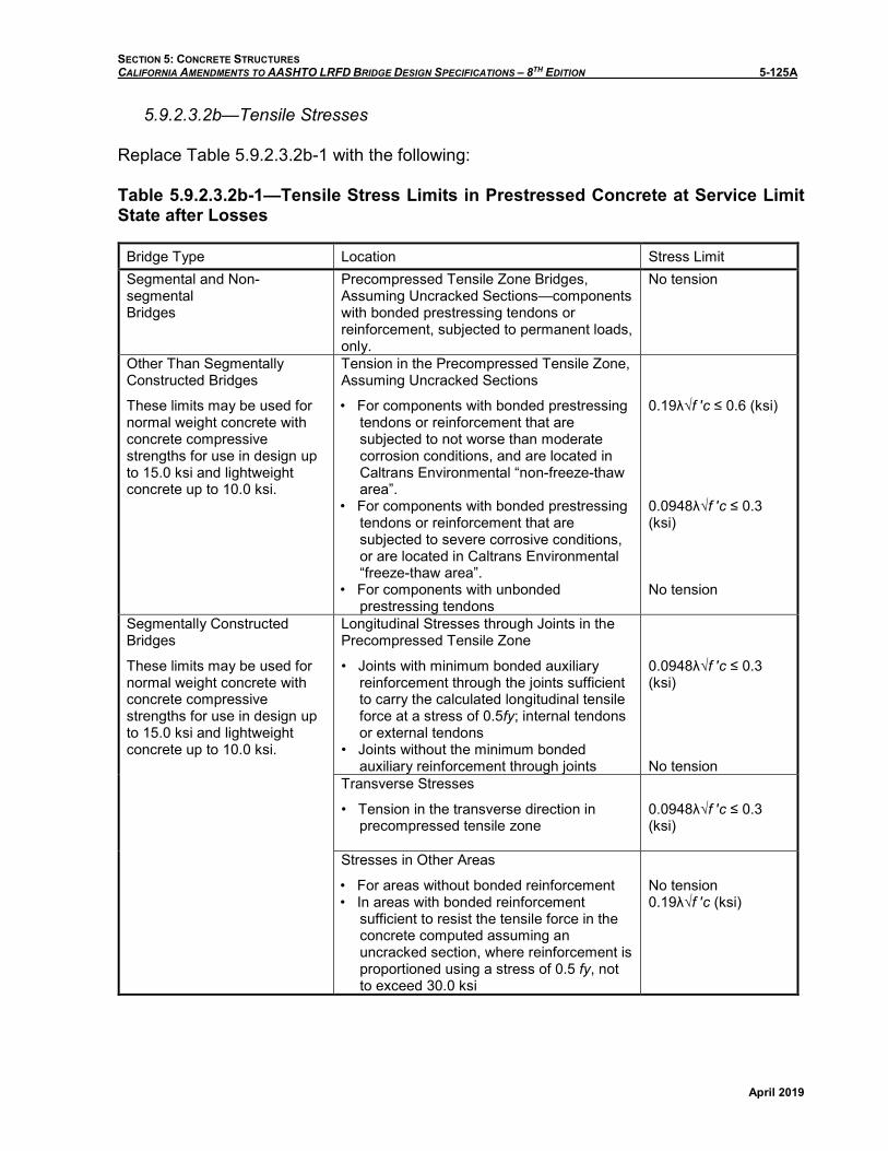
5.9.2.3.2b—Tensile Stresses
Replace Table 5.9.2.3.2b-1 with the following:
Table 5.9.2.3.2b-1—Tensile Stress Limits in Prestressed Concrete at Service Limit State after Losses
Bridge Type Location Stress Limit Segmental and Non-segmental Bridges
Precompressed Tensile Zone Bridges, Assuming Uncracked Sections—components with bonded prestressing tendons or reinforcement, subjected to permanent loads, only.
No tension
Other Than Segmentally Constructed Bridges
These limits may be used for normal weight concrete with concrete compressive strengths for use in design up to 15.0 ksi and lightweight concrete up to 10.0 ksi.
Tension in the Precompressed Tensile Zone, Assuming Uncracked Sections
• For components with bonded prestressing tendons or reinforcement that are subjected to not worse than moderate corrosion conditions, and are located in Caltrans Environmental “non-freeze-thaw area”.
• For components with bonded prestressing tendons or reinforcement that are subjected to severe corrosive conditions, or are located in Caltrans Environmental “freeze-thaw area”.
• For components with unbonded prestressing tendons
0.19λ√f ′c ≤ 0.6 (ksi)
0.0948λ√f ′c ≤ 0.3 (ksi)
No tension
Segmentally Constructed Bridges
These limits may be used for normal weight concrete with concrete compressive strengths for use in design up to 15.0 ksi and lightweight concrete up to 10.0 ksi.
Longitudinal Stresses through Joints in the Precompressed Tensile Zone
• Joints with minimum bonded auxiliary reinforcement through the joints sufficient to carry the calculated longitudinal tensile force at a stress of 0.5fy; internal tendons or external tendons
• Joints without the minimum bonded auxiliary reinforcement through joints
0.0948λ√f ′c ≤ 0.3 (ksi)
No tension Transverse Stresses
• Tension in the transverse direction in precompressed tensile zone
0.0948λ√f ′c ≤ 0.3 (ksi)
Stresses in Other Areas
• For areas without bonded reinforcement • In areas with bonded reinforcement
sufficient to resist the tensile force in the concrete computed assuming an uncracked section, where reinforcement is proportioned using a stress of 0.5 fy, not to exceed 30.0 ksi
No tension 0.19λ√f ′c (ksi)

SECTION 5: CONCRETE STRUCTURES CALIFORNIA AMENDMENTS TO AASHTO LRFD BRIDGE DESIGN SPECIFICATIONS – 8TH EDITION 5-125B
April 2019
This page intentionally left blank.
SECTION 5: CONCRETE STRUCTURES CALIFORNIA AMENDMENTS TO AASHTO LRFD BRIDGE DESIGN SPECIFICATIONS – 8TH EDITION 5-130A
April 2019
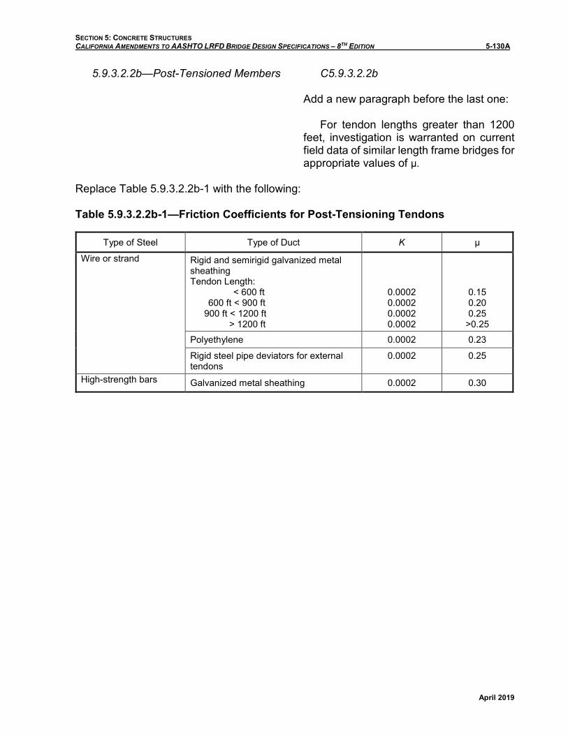
5.9.3.2.2b—Post-Tensioned Members C5.9.3.2.2b
Add a new paragraph before the last one:
For tendon lengths greater than 1200 feet, investigation is warranted on current field data of similar length frame bridges for appropriate values of μ.
Replace Table 5.9.3.2.2b-1 with the following:
Table 5.9.3.2.2b-1—Friction Coefficients for Post-Tensioning Tendons
Type of Steel Type of Duct K μ
Wire or strand Rigid and semirigid galvanized metal sheathing Tendon Length:
< 600 ft 600 ft < 900 ft
900 ft < 1200 ft > 1200 ft
0.0002 0.0002 0.0002 0.0002
0.15 0.20 0.25
>0.25 Polyethylene 0.0002 0.23
Rigid steel pipe deviators for external tendons
0.0002 0.25
High-strength bars Galvanized metal sheathing 0.0002 0.30

SECTION 5: CONCRETE STRUCTURES CALIFORNIA AMENDMENTS TO AASHTO LRFD BRIDGE DESIGN SPECIFICATIONS – 8TH EDITION 5-130B
April 2019
This page intentionally left blank.

SECTION 5: CONCRETE STRUCTURES CALIFORNIA AMENDMENTS TO AASHTO LRFD BRIDGE DESIGN SPECIFICATIONS – 8TH EDITION 5-132A
April 2019
5.9.3.2.3b—Post Tensioned Members
Replace Equation 5.9.3.2.3b-1 with the following:
ΔfpES = 0.5 Ep
Ecifcgp (5.9.3.2.3b-1)
C5.9.3.2.3b
Replace Equation C5.9.3.2.3b-1 with the following:
ΔfpES = 0.5Apsfpbt(Ig+em
2 Ag) - emMgAg
Aps(Ig+em2 Ag) +
AgIgEciEp
(C5.9.3.2.3b-1)

SECTION 5: CONCRETE STRUCTURES CALIFORNIA AMENDMENTS TO AASHTO LRFD BRIDGE DESIGN SPECIFICATIONS – 8TH EDITION 5-132B
April 2019
This page intentionally left blank.
SECTION 5: CONCRETE STRUCTURES CALIFORNIA AMENDMENTS TO AASHTO LRFD BRIDGE DESIGN SPECIFICATIONS – 8TH EDITION 5-134A
April 2019
5.9.3.3—Approximate Estimate of Time Dependent Losses
Add a new last paragraph:
For cast-in-place post-tensioned members, the approximate estimate of time-dependent losses may be taken as the lump sum value of 20 ksi.
C5.9.3.3
Add a new last paragraph:
The expressions for estimating time-dependent losses in Eq. 5.9.3.3-1 were developed for pretensioned members and should not be used for post-tensioned structures. Research performed by the University of California, San Diego (SSRP-11/02) indicates time-dependent losses for cast-in-place post-tensioned box girder bridges are lower than previously expected. A parametric study using equations presented in the aforementioned research indicates losses may range from 11 ksi to 21 ksi. The variance is due to several parameters, such as relative humidity, area of nonprestressing steel, and strength of concrete.

SECTION 5: CONCRETE STRUCTURES CALIFORNIA AMENDMENTS TO AASHTO LRFD BRIDGE DESIGN SPECIFICATIONS – 8TH EDITION 5-134B
April 2019
This page intentionally left blank.

SECTION 5: CONCRETE STRUCTURES CALIFORNIA AMENDMENTS TO AASHTO LRFD BRIDGE DESIGN SPECIFICATIONS – 8TH EDITION 5-142A
April 2019
5.9.4.3.3—Debonded Strands
Replace the 2nd paragraph with the following:
The number of partially debonded strands shall not exceed 33 percent of the total number of strands.
Replace the 3rd paragraph with the following:
The number of debonded strands in any horizontal row shall not exceed 50 percent of the strands in that row.

SECTION 5: CONCRETE STRUCTURES CALIFORNIA AMENDMENTS TO AASHTO LRFD BRIDGE DESIGN SPECIFICATIONS – 8TH EDITION 5-142B
April 2019
This page intentionally left blank.
SECTION 5: CONCRETE STRUCTURES CALIFORNIA AMENDMENTS TO AASHTO LRFD BRIDGE DESIGN SPECIFICATIONS – 8TH EDITION 5-145A
April 2019
5.9.5.1.1—Post-Tensioning Ducts–Girders Straight in Plan
Replace the 2nd paragraph with the following:
Ducts less than 4-½ in. OD may be bundled together in groups, provided that the spacing, as specified between individual ducts, is maintained between each duct in the zone within 3.0 ft of anchorages.

SECTION 5: CONCRETE STRUCTURES CALIFORNIA AMENDMENTS TO AASHTO LRFD BRIDGE DESIGN SPECIFICATIONS – 8TH EDITION 5-145B
April 2019
This page intentionally left blank.
SECTION 5: CONCRETE STRUCTURES CALIFORNIA AMENDMENTS TO AASHTO LRFD BRIDGE DESIGN SPECIFICATIONS – 8TH EDITION 5-164A
April 2019
5.10.1—Concrete Cover
Replace the article with the following:
The minimum concrete cover for protection of reinforcement against corrosion due to chlorides shall be as provided in Table 5.10.1-1.
"Corrosive" water or soil contains greater than or equal to 500 parts per million (ppm) of chlorides. Sites that are considered corrosive due solely to sulfate content greater than or equal to 1,500 ppm and/or a pH of less than or equal to 5.5 shall be considered non-corrosive in determining minimum cover from Table 5.10.1-1, but shall conform to the requirements of Article 5.14.6.
The splash zone is defined as the region from 3 ft below the Mean Lower Low Water (MLLW) elevation to 20 ft above the Mean Higher High Water (MHHW) elevation and a horizontal distance of 20 ft from the edge of water at the MHHW elevation.
Marine atmosphere includes both the atmosphere over land within 1,000 ft of ocean or marine water, and the atmosphere above the splash zone. Marine water, from corrosion considerations, is any body of water having a chloride content greater than or equal to 500 ppm.
For bundled bars, the minimum concrete cover in non-corrosive environments shall be equal to the equivalent diameter of the bundle, but need not be greater than 2 inches, except for concrete cast against and permanently exposed to non-corrosive soil, where the minimum cover shall be 3 inches. In corrosive environments, the cover shall be the same as that specified in Table 5.10.1-1, except that it shall not be less than the cover specified for bundled bars in non-corrosive environments.
C5.10.1
Replace the commentary with the following:
The table for minimum concrete cover for protection against corrosion has been developed for a 75-year design life. However, the service life of bridge decks is typically less than 75 years. Therefore, concrete mix design for bridge decks has incorporated additional measures in Caltrans practice (adding polymer fibers, limiting W/C ratio, ensuring min. cementitious materials) to extend the service life of decks.
Environmental conditions such as proximity to corrosive atmosphere, marine environment, wave action, water table elevation and chloride content have been incorporated in determining the cover requirements.
Corrosion protection can be improved by increasing concrete denseness or imperviousness to water, as well as by furnishing other protection methods. Such methods include:
a) a reduction in water-to-cementitious material ratio;
b) incorporating supplementary cementitious materials into concrete mix design.
c) use of different kinds of epoxy-coated reinforcing bars (ECR);
d) protective concrete coatings; e) use of chemical admixtures; f) cathodic protection, and, g) use of alternate materials.

SECTION 5: CONCRETE STRUCTURES CALIFORNIA AMENDMENTS TO AASHTO LRFD BRIDGE DESIGN SPECIFICATIONS – 8TH EDITION 5-164B
April 2019
In corrosive environments, the minimum concrete cover to prestressing steel not placed within ducts, shall be the same as that specified for reinforcement (Table 5.10.1-1), except that when epoxy-coated reinforcement is required per Table 5.10.1-1, the prestressing steel shall be epoxy-coated as specified in Standard Specifications, or the minimum concrete cover to the prestressing steel shall be increased by 1.0 inch beyond that specified in Table 5.10.1-1.
Ducts for internal post-tensioned tendons, designed to provide bonded resistance, shall be grouted after stressing.
Other tendons shall be permanently protected against corrosion and the details of protection shall be indicated in the contract documents.
The minimum concrete cover for protection of ducts in a corrosive environment shall be the same as that specified for reinforcement in Table 5.10.1-1, except that the concrete cover over the duct shall not be less than one-half the diameter of the duct; and, when epoxy-coated is required, the minimum concrete cover over the duct shall be increased by 0.50 inches beyond that specified for reinforcement in in Table 5.10.1-1, but shall not be less than one-half the diameter of the duct.
The minimum concrete cover, concrete mix, and epoxy-coated reinforcement requirements for structural elements exposed to deicing salt, snow run-off, or snow blower spray shall be adopted only if the Engineer determines that the structural elements are directly exposed to these corrosive conditions. For example, when the deck is subjected to deicing salt, snow run-off or snow blower spray, it is unlikely that the girders or bent cap will be exposed to the same harsh condition, particularly when there are no deck joints. Therefore, the girders and the bent cap may be designed for a non-corrosive exposure condition.
If other considerations, such as a need to reduce the dead load of a structure, require a further reduction in concrete cover than those specified in Table 5.10.1-1, then a reduction in cover should only be done after a thorough investigation and research into existing state-of-practice.
In certain cases, such as the tying together of longitudinal precast elements by transverse post-tensioning, the integrity of the structure does not depend on the bonded resistance of the tendons, but rather on the confinement provided by the prestressing elements.
Unbonded tendons can be more readily inspected and replaced, one at a time, if so required.
External tendons have been successfully protected by cement grout in polyethylene or metal tubing. Tendons have also been protected by heavy grease or other anticorrosion medium where future replacement is envisioned. Tendon anchorage regions should be protected by encapsulation or other effective means. This is critical in unbonded tendons because any failure of the anchorage can release the entire tendon.
SECTION 5: CONCRETE STRUCTURES CALIFORNIA AMENDMENTS TO AASHTO LRFD BRIDGE DESIGN SPECIFICATIONS – 8TH EDITION 5-164C
April 2019
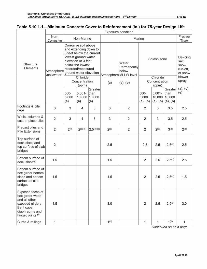
Table 5.10.1-1—Minimum Concrete Cover to Reinforcement (in.) for 75-year Design Life
Structural Elements
Exposure condition Non-
Corrosive Non-Marine Marine Freeze/ Thaw
Atmosphere /soil/water
Corrosive soil above and extending down to 3 feet below the current lowest ground water elevation or 3 feet below the lowest recorded/measured ground water elevation
Atmosphere
(a)
Water Permanently below MLLW level (a), (b)
Splash zone
De-icing salt, snow run-off, or snow blower spray (a), (c), (e)
Chloride Concentration
(ppm)
Chloride Concentration
(ppm)
500- 5,000 (a)
5,001- 10,000 (a)
Greater than 10,000 (a)
500- 5,000 (a), (b)
5,001- 10,000 (a), (b)
Greater than 10,000 (a), (b)
Footings & pile caps 3 3 4 5 3 2 2 3 3.5 2.5
Walls, columns & cast-in-place piles 2 3 4 5 3 2 2 3 3.5 2.5
Precast piles and Pile Extensions 2 2(d) 2(b) (d) 2.5(b) (d) 2(d) 2 2 2(d) 3(d) 2(d)
Top surface of deck slabs and top surface of slab bridges
2 2.5 2.5 2.5 2.5(d) 2.5
Bottom surface of deck slabs(g) 1.5 1.5 2 2.5 2.5(d) 2.5
Bottom surface of box girder bottom slabs and bottom surface of slab bridges
1.5 1.5 2 2.5 2.5(d) 1.5
Exposed faces of box girder webs and all other exposed girders. Bent caps, diaphragms and hinged joints (f)
1.5 3.0 2 2.5 2.5(d) 3.0
Curbs & railings 1 1(b) 1 1 1(d) 1 Continued on next page
SECTION 5: CONCRETE STRUCTURES CALIFORNIA AMENDMENTS TO AASHTO LRFD BRIDGE DESIGN SPECIFICATIONS – 8TH EDITION 5-164D
April 2019
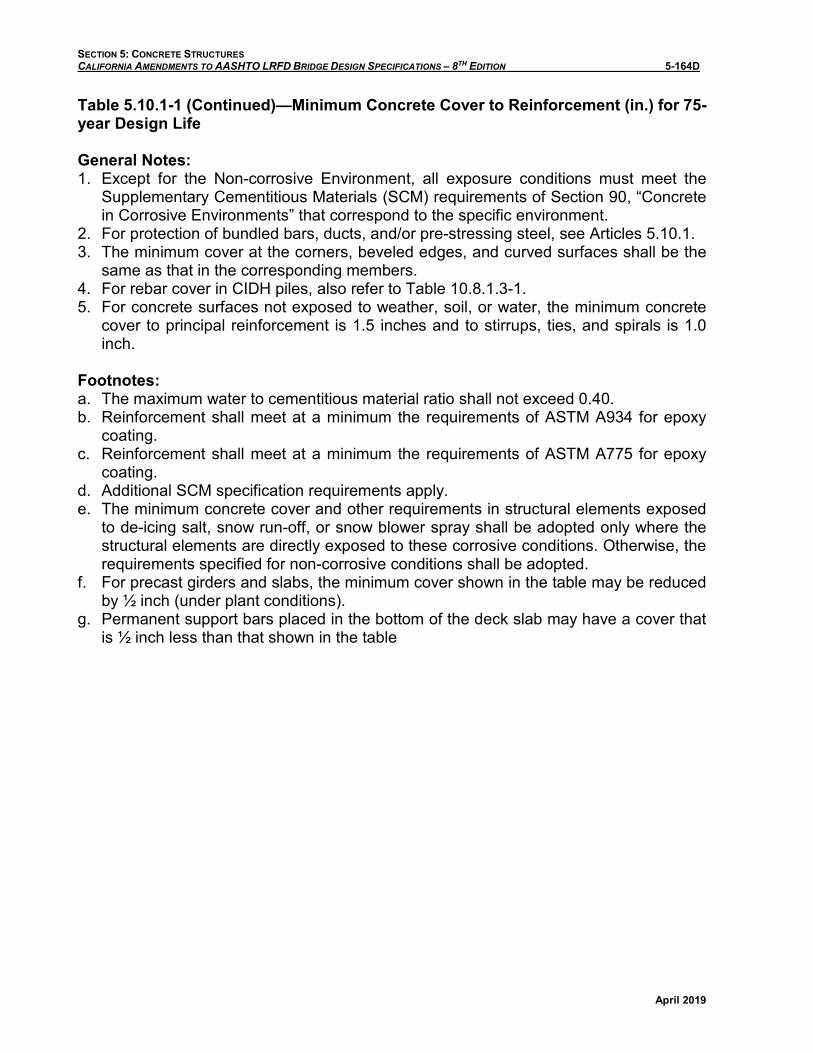
Table 5.10.1-1 (Continued)—Minimum Concrete Cover to Reinforcement (in.) for 75-year Design Life
General Notes: 1. Except for the Non-corrosive Environment, all exposure conditions must meet the
Supplementary Cementitious Materials (SCM) requirements of Section 90, “Concrete in Corrosive Environments” that correspond to the specific environment.
2. For protection of bundled bars, ducts, and/or pre-stressing steel, see Articles 5.10.1. 3. The minimum cover at the corners, beveled edges, and curved surfaces shall be the
same as that in the corresponding members. 4. For rebar cover in CIDH piles, also refer to Table 10.8.1.3-1. 5. For concrete surfaces not exposed to weather, soil, or water, the minimum concrete
cover to principal reinforcement is 1.5 inches and to stirrups, ties, and spirals is 1.0 inch.
Footnotes: a. The maximum water to cementitious material ratio shall not exceed 0.40. b. Reinforcement shall meet at a minimum the requirements of ASTM A934 for epoxy
coating. c. Reinforcement shall meet at a minimum the requirements of ASTM A775 for epoxy
coating. d. Additional SCM specification requirements apply. e. The minimum concrete cover and other requirements in structural elements exposed
to de-icing salt, snow run-off, or snow blower spray shall be adopted only where the structural elements are directly exposed to these corrosive conditions. Otherwise, the requirements specified for non-corrosive conditions shall be adopted.
f. For precast girders and slabs, the minimum cover shown in the table may be reduced by ½ inch (under plant conditions).
g. Permanent support bars placed in the bottom of the deck slab may have a cover that is ½ inch less than that shown in the table
SECTION 5: CONCRETE STRUCTURES CALIFORNIA AMENDMENTS TO AASHTO LRFD BRIDGE DESIGN SPECIFICATIONS – 8TH EDITION 5-172A
April 2019
5.10.8.1—General
Replace the 1st paragraph with the following:
The provisions of Articles 5.10.8.2.1a, b, c, 5.10.8.2.4, and 5.10.8.4.3a are valid for No. 11 bars or smaller, in normal weight concrete with design concrete compressive strength (f′c) of up to 15.0 ksi and lightweight concrete up to 10.0 ksi, subject to the limitations as specified in each of these articles.

SECTION 5: CONCRETE STRUCTURES CALIFORNIA AMENDMENTS TO AASHTO LRFD BRIDGE DESIGN SPECIFICATIONS – 8TH EDITION 5-172B
April 2019
This page intentionally left blank.

SECTION 5: CONCRETE STRUCTURES CALIFORNIA AMENDMENTS TO AASHTO LRFD BRIDGE DESIGN SPECIFICATIONS – 8TH EDITION 5-176A
April 2019
5.10.8.2.1—Deformed Bars and Deformed Wire in Tension
Replace the 1st paragraph with the following:
The provisions of Articles 5.10.8.2.1a, b, c, may be used for No. 11 bars and smaller in normal weight concrete with a compressive strength of concrete for use in design up to 15.0 ksi and lightweight concrete up to 10.0 ksi. Transverse reinforcement consisting of at least No. 3 bars at 12.0-in. centers shall be provided along the required development length where the design concrete compressive strength is greater than 10.0 ksi. The provisions of Article 5.10.8.2.1d may be used for concrete with a design compressive strength up to 10.0 ksi.
Replace the 2nd paragraph with the following:
For straight bars having a specified minimum yield strength greater than 75.0 ksi, transverse reinforcement satisfying the requirements of Article 5.7.2.5 for beams and Article 5.10.4.3 for columns shall be provided over the required development length. Confining reinforcement is not required in bridge slabs or decks.

SECTION 5: CONCRETE STRUCTURES CALIFORNIA AMENDMENTS TO AASHTO LRFD BRIDGE DESIGN SPECIFICATIONS – 8TH EDITION 5-176B
April 2019
This page intentionally left blank.

SECTION 5: CONCRETE STRUCTURES CALIFORNIA AMENDMENTS TO AASHTO LRFD BRIDGE DESIGN SPECIFICATIONS – 8TH EDITION 5-178A
April 2019
Add the following article:
5.10.8.2.1d—Tension Development Length Alternative Method
In lieu of Articles 5.10.8.2.1a, b, c, the modified tension development length, ld, may be determined as specified in this Article for concrete with design compressive strength up to 10.0 ksi.
The modified tension development length, ld, shall not be less than the product of the basic tension development length, ldb, and the modification factor or factors specified herein. The modified tension development length shall not be less than 12.0 in., except for development of shear reinforcement specified in Article 5.10.8.2.6.
The basic tension development length, ldb, in in. shall be taken as:
• For No. 11 bar and smaller ...... 1.25Abfy
�fc'
• but not less than ..................... 0.4 db fy
• For No. 14 bars ............................ 2.7fy
�fc'
• For No. 18 bars ............................ 3.5fy
�fc'
• For deformed wire .................... 0.95dbfy
�fc'
where:
Ab = area of bar (in.2) fy = specified yield strength of
reinforcing bars (ksi) f ′c = design compressive strength of
concrete at 28 days (ksi), unless another age is specified, not exceeding 10 ksi
db = diameter of bar (in.)
SECTION 5: CONCRETE STRUCTURES CALIFORNIA AMENDMENTS TO AASHTO LRFD BRIDGE DESIGN SPECIFICATIONS – 8TH EDITION 5-178B
April 2019
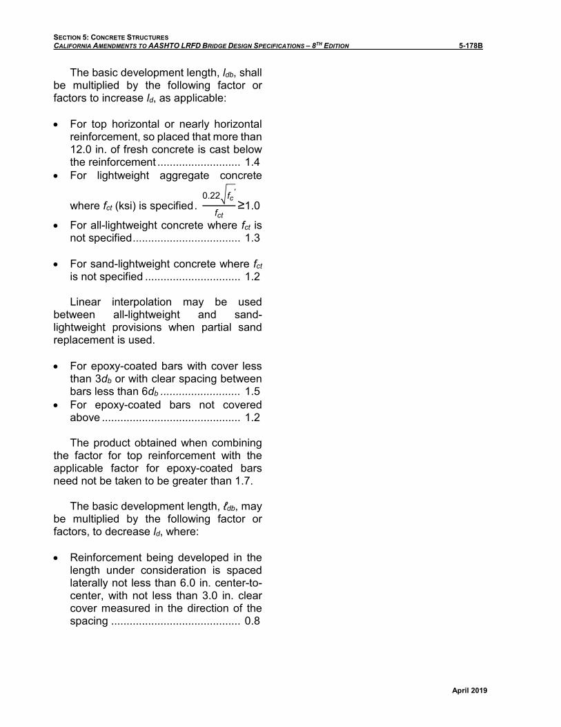
The basic development length, ldb, shall be multiplied by the following factor or factors to increase ld, as applicable:
• For top horizontal or nearly horizontal reinforcement, so placed that more than 12.0 in. of fresh concrete is cast below the reinforcement ........................... 1.4
• For lightweight aggregate concrete
where fct (ksi) is specified . 0.22�fc
'
fct≥1.0
• For all-lightweight concrete where fct is not specified ................................... 1.3
• For sand-lightweight concrete where fct is not specified ............................... 1.2
Linear interpolation may be used between all-lightweight and sand-lightweight provisions when partial sand replacement is used.
• For epoxy-coated bars with cover less than 3db or with clear spacing between bars less than 6db .......................... 1.5
• For epoxy-coated bars not covered above ............................................. 1.2
The product obtained when combining the factor for top reinforcement with the applicable factor for epoxy-coated bars need not be taken to be greater than 1.7.
The basic development length, ℓdb, may be multiplied by the following factor or factors, to decrease ld, where:
• Reinforcement being developed in the length under consideration is spaced laterally not less than 6.0 in. center-to-center, with not less than 3.0 in. clear cover measured in the direction of the spacing .......................................... 0.8
SECTION 5: CONCRETE STRUCTURES CALIFORNIA AMENDMENTS TO AASHTO LRFD BRIDGE DESIGN SPECIFICATIONS – 8TH EDITION 5-178C
April 2019
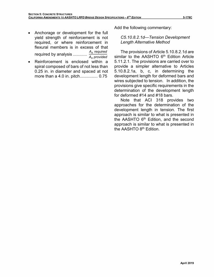
• Anchorage or development for the full yield strength of reinforcement is notrequired, or where reinforcement inflexural members is in excess of that required by analysis ............
As requiredAs provided
• Reinforcement is enclosed within a
spiral composed of bars of not less than 0.25 in. in diameter and spaced at not more than a 4.0 in. pitch ............... 0.75
Add the following commentary:
C5.10.8.2.1d—Tension Development Length Alternative Method
The provisions of Article 5.10.8.2.1d are similar to the AASHTO 6th Edition Article 5.11.2.1. The provisions are carried over to provide a simpler alternative to Articles 5.10.8.2.1a, b, c, in determining the development length for deformed bars and wires subjected to tension. In addition, the provisions give specific requirements in the determination of the development length for deformed #14 and #18 bars.
Note that ACI 318 provides two approaches for the determination of the development length in tension. The first approach is similar to what is presented in the AASHTO 6th Edition, and the second approach is similar to what is presented in the AASHTO 8th Edition.

SECTION 5: CONCRETE STRUCTURES CALIFORNIA AMENDMENTS TO AASHTO LRFD BRIDGE DESIGN SPECIFICATIONS – 8TH EDITION 5-178D
April 2019
This page intentionally left blank.
SECTION 5: CONCRETE STRUCTURES CALIFORNIA AMENDMENTS TO AASHTO LRFD BRIDGE DESIGN SPECIFICATIONS – 8TH EDITION 5-183A
April 2019
5.10.8.2.5a—Welded Deformed Wire Reinforcement
Replace the 4th paragraph with the following:
The basic development length of welded deformed wire reinforcement, with no cross wires within the development length, shall be determined as for deformed wire in accordance with Article 5.10.8.2.1.

SECTION 5: CONCRETE STRUCTURES CALIFORNIA AMENDMENTS TO AASHTO LRFD BRIDGE DESIGN SPECIFICATIONS – 8TH EDITION 5-183B
April 2019
This page intentionally left blank.
SECTION 5: CONCRETE STRUCTURES CALIFORNIA AMENDMENTS TO AASHTO LRFD BRIDGE DESIGN SPECIFICATIONS – 8TH EDITION 5-187A
April 2019
5.10.8.4.3a—Lap Splices in Tension
Replace the 2nd paragraph with the following:
The tension development length, ld, for the specified yield strength shall be taken in accordance with Article 5.10.8.2.1.

SECTION 5: CONCRETE STRUCTURES CALIFORNIA AMENDMENTS TO AASHTO LRFD BRIDGE DESIGN SPECIFICATIONS – 8TH EDITION 5-187B
April 2019
This page intentionally left blank.
SECTION 5: CONCRETE STRUCTURES CALIFORNIA AMENDMENTS TO AASHTO LRFD BRIDGE DESIGN SPECIFICATIONS – 8TH EDITION 5-207A
April 2019
5.12.3.3.1—General
Replace the 1st paragraph with the following:
The provisions of this Article shall apply at the service and strength limit states as applicable. Article 5.12.3.3 need not be applied to the design of multi-span bridges composed of precast girders with continuity diaphragms at bent caps.
C5.12.3.3.1
Add a new 1st paragraph as follows:
Historically, Caltrans has not explicitly designed for the requirements of 5.12.3.3 and has not experienced any negative performance issues using current design practice, standard details and construction methods for multi-span bridges composed of precast girders with continuity diaphragms at bent caps.

SECTION 5: CONCRETE STRUCTURES CALIFORNIA AMENDMENTS TO AASHTO LRFD BRIDGE DESIGN SPECIFICATIONS – 8TH EDITION 5-207B
April 2019
This page intentionally left blank.

SECTION 5: CONCRETE STRUCTURES CALIFORNIA AMENDMENTS TO AASHTO LRFD BRIDGE DESIGN SPECIFICATIONS – 8TH EDITION 5-228A
April 2019
5.12.5.3.8—Alternative Shear Design Procedure
Replace the entire article with the following:
Article 5.7.3 shall be used for the shear and torsion design of segmental post-tensioned box girders bridges.

SECTION 5: CONCRETE STRUCTURES CALIFORNIA AMENDMENTS TO AASHTO LRFD BRIDGE DESIGN SPECIFICATIONS – 8TH EDITION 5-228B
April 2019
This page intentionally left blank.
SECTION 5: CONCRETE STRUCTURES CALIFORNIA AMENDMENTS TO AASHTO LRFD BRIDGE DESIGN SPECIFICATIONS – 8TH EDITION 5-253A
April 2019
5.12.9.5.2—Reinforcement
Add the following paragraph to the end of the article:
Minimum shear reinforcement in drilled shafts shall be No. 5 hoops at 12 in. center to center spacing or equivalent spiral reinforcement, when permitted. Radial bundling of longitudinal reinforcement shall not be used in drilled shafts.
5.13—ANCHORS
5.13.1—General
Replace the last paragraph with the following:
Corrosion control shall be considered in any anchor application exposed to the elements. ASTM F1554 Grade 105 anchor bolts shall not be galvanized. No cleaning process shall be used that will introduce hydrogen into steel.
C5.13.1
Replace the last paragraph with the following:
Typical corrosion protection consists of the use of coatings or corrosion resistant materials. For adhesive anchors the manufacturer’s literature must document that the adhesive used is compatible with the type and extent of any coating used. Galvanization of ASTM F1554 Grade 105 anchor bolts is not permitted due to potential hydrogen embrittlement. These anchors should be carefully evaluated before use with applicable protective coatings conforming to ASTM F1554 Specifications.

SECTION 5: CONCRETE STRUCTURES CALIFORNIA AMENDMENTS TO AASHTO LRFD BRIDGE DESIGN SPECIFICATIONS – 8TH EDITION 5-253B
April 2019
This page intentionally left blank.
SECTION 5: CONCRETE STRUCTURES CALIFORNIA AMENDMENTS TO AASHTO LRFD BRIDGE DESIGN SPECIFICATIONS – 8TH EDITION 5-261A
April 2019
Replace the article including its title for 5.14.6 with the following:
5.14.6—Protection of Concrete Exposed to Acids and Sulfate
The durability of concrete may be adversely affected by contact with acids and sulfates present in soil or water. When concrete is exposed to an acidic and/or a sulfate environment, then a special concrete mix design is required.
C5.14.6
Delete the entire commentary.

SECTION 5: CONCRETE STRUCTURES CALIFORNIA AMENDMENTS TO AASHTO LRFD BRIDGE DESIGN SPECIFICATIONS – 8TH EDITION 5-261B
April 2019
This page intentionally left blank.
SECTION 5: CONCRETE STRUCTURES CALIFORNIA AMENDMENTS TO AASHTO LRFD BRIDGE DESIGN SPECIFICATIONS – 8TH EDITION 5-279A
April 2019
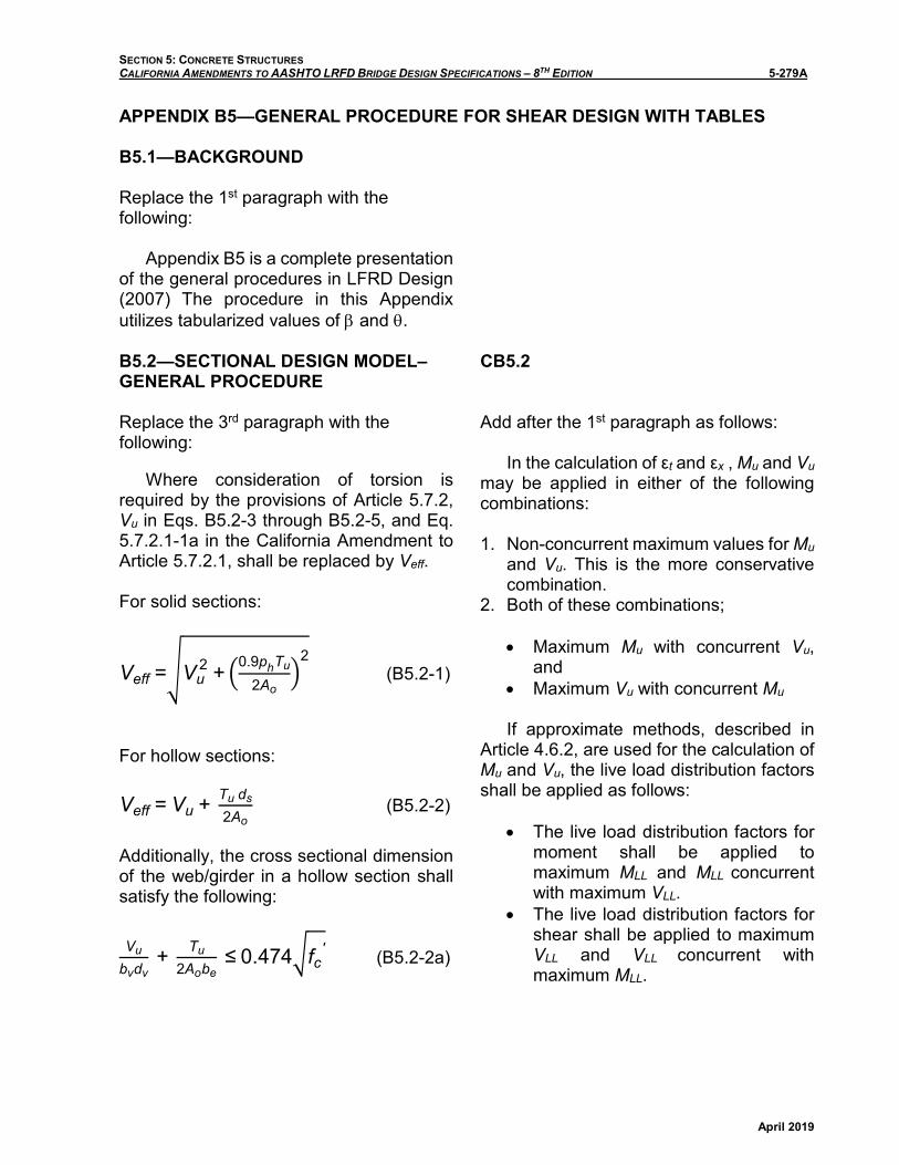
APPENDIX B5—GENERAL PROCEDURE FOR SHEAR DESIGN WITH TABLES
B5.1—BACKGROUND
Replace the 1st paragraph with the following:
Appendix B5 is a complete presentation of the general procedures in LFRD Design (2007) The procedure in this Appendix utilizes tabularized values of β and θ.
B5.2—SECTIONAL DESIGN MODEL–GENERAL PROCEDURE
Replace the 3rd paragraph with the following:
Where consideration of torsion is required by the provisions of Article 5.7.2, Vu in Eqs. B5.2-3 through B5.2-5, and Eq. 5.7.2.1-1a in the California Amendment to Article 5.7.2.1, shall be replaced by Veff.
For solid sections:
Veff =�Vu 2 + �0.9phTu
2Ao�
2 (B5.2-1)
For hollow sections:
Veff = Vu + Tu ds
2Ao (B5.2-2)
Additionally, the cross sectional dimension of the web/girder in a hollow section shall satisfy the following:
Vu
bvdv + Tu
2Aobe ≤ 0.474�fc
' (B5.2-2a)
CB5.2
Add after the 1st paragraph as follows:
In the calculation of εt and εx , Mu and Vu may be applied in either of the following combinations:
1. Non-concurrent maximum values for Mu and Vu. This is the more conservative combination.
2. Both of these combinations;
• Maximum Mu with concurrent Vu, and
• Maximum Vu with concurrent Mu
If approximate methods, described in Article 4.6.2, are used for the calculation of Mu and Vu, the live load distribution factors shall be applied as follows:
• The live load distribution factors for moment shall be applied to maximum MLL and MLL concurrent with maximum VLL.
• The live load distribution factors for shear shall be applied to maximum VLL and VLL concurrent with maximum MLL.
SECTION 5: CONCRETE STRUCTURES CALIFORNIA AMENDMENTS TO AASHTO LRFD BRIDGE DESIGN SPECIFICATIONS – 8TH EDITION 5-279B
April 2019
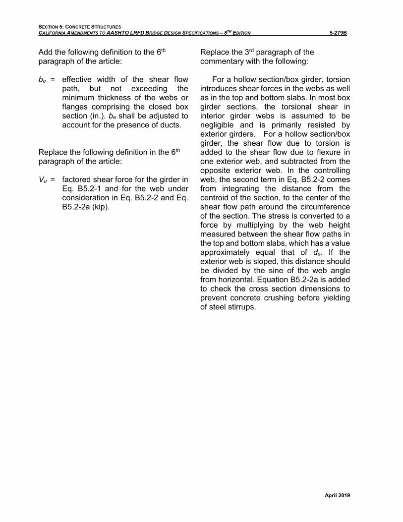
Add the following definition to the 6th paragraph of the article:
be = effective width of the shear flow path, but not exceeding the minimum thickness of the webs or flanges comprising the closed box section (in.). be shall be adjusted to account for the presence of ducts.
Replace the following definition in the 6th paragraph of the article:
Vu = factored shear force for the girder in Eq. B5.2-1 and for the web under consideration in Eq. B5.2-2 and Eq. B5.2-2a (kip).
Replace the 3rd paragraph of the commentary with the following:
For a hollow section/box girder, torsion introduces shear forces in the webs as well as in the top and bottom slabs. In most box girder sections, the torsional shear in interior girder webs is assumed to be negligible and is primarily resisted by exterior girders. For a hollow section/box girder, the shear flow due to torsion is added to the shear flow due to flexure in one exterior web, and subtracted from the opposite exterior web. In the controlling web, the second term in Eq. B5.2-2 comes from integrating the distance from the centroid of the section, to the center of the shear flow path around the circumference of the section. The stress is converted to a force by multiplying by the web height measured between the shear flow paths in the top and bottom slabs, which has a value approximately equal that of ds. If the exterior web is sloped, this distance should be divided by the sine of the web angle from horizontal. Equation B5.2-2a is added to check the cross section dimensions to prevent concrete crushing before yielding of steel stirrups.