Section 90 Chapter 2 - dmcpubs.com · SECTION 90 - CAB RAISE/REMOVAL AND INSTALLATION - CHAPTER 2...
20
Section 90 Chapter 2 6-13310NH CAB RAISE / REMOVAL AND INSTALLATION TG Series Tractors
Transcript of Section 90 Chapter 2 - dmcpubs.com · SECTION 90 - CAB RAISE/REMOVAL AND INSTALLATION - CHAPTER 2...

Section 90
Chapter 2
6-13310NH
CAB RAISE / REMOVAL AND INSTALLATION
TG Series Tractors

SECTION 90 - CAB RAISE/REMOVAL AND INSTALLATION - CHAPTER 2
90-2
TABLE OF CONTENTS
SPECIAL TORQUES .......................................................................................................................................... 90-3
SPECIAL TOOLS ............................................................................................................................................... 90-4
CAB RAISING PROCEDURE ............................................................................................................................ 90-5
CAB LOWERING PROCEDURE ........................................................................................................................ 90-8
CAB REMOVAL ................................................................................................................................................ 90-11
CAB INSTALLATION ........................................................................................................................................ 90-16

SECTION 90 - CAB RAISE/REMOVAL AND INSTALLATION - CHAPTER 2
90-3
SPECIAL TORQUESCab Mounting Bolt to Threaded Flat Plate ....................................................................... 47 to 61 Nm (35 to 45 lb ft)Cab Mounting Bolt Nut ............................................................................................. 190 to 244 Nm (140 to 180 lb ft)
SECTION 90 - CAB RAISE/REMOVAL AND INSTALLATION - CHAPTER 2
90-4
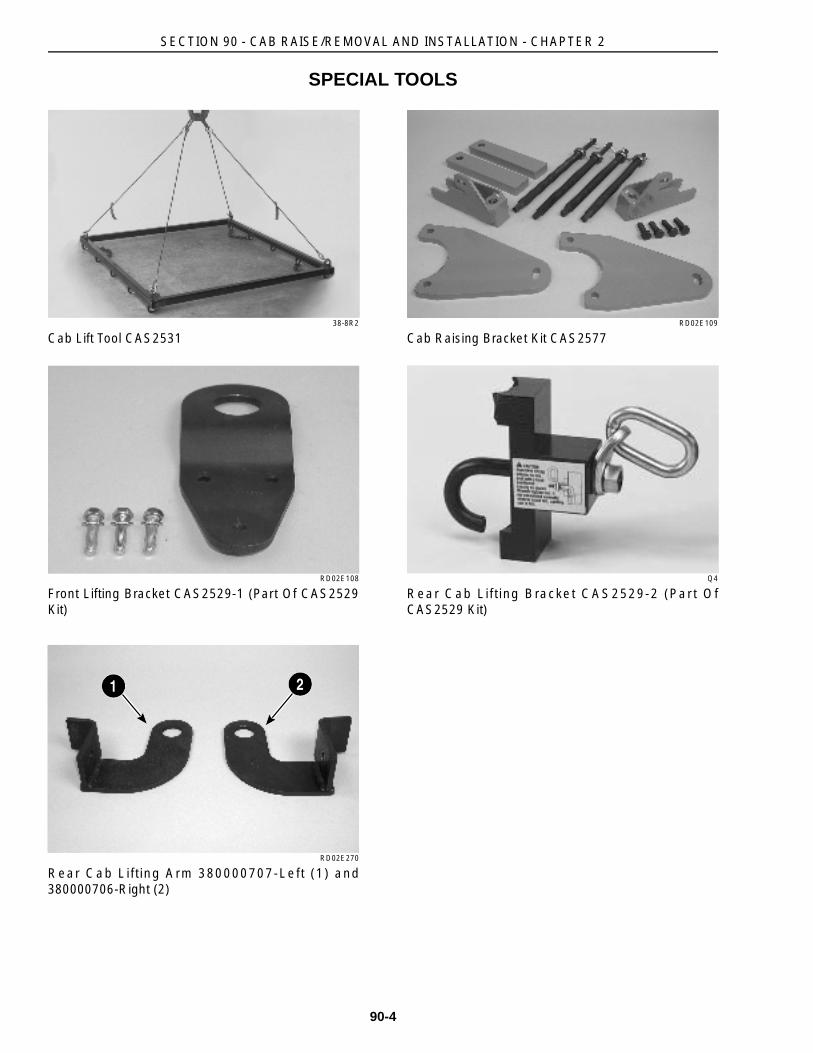
SPECIAL TOOLS
38-8R2
Cab Lift Tool CAS2531
RD02E108
Front Lifting Bracket CAS2529-1 (Part Of CAS2529Kit)
RD02E270
Rear Cab Lifting Arm 380000707-Left (1) and380000706-Right (2)
RD02E109
Cab Raising Bracket Kit CAS2577
Q4
Rear Cab Lifting Bracket CAS2529-2 (Par t OfCAS2529 Kit)
21

SECTION 90 - CAB RAISE/REMOVAL AND INSTALLATION - CHAPTER 2
90-5
CAB RAISING PROCEDURE
STEP 1
RD02C070
Park the tractor on a hard, level surface. Put thetransmission shift lever in PARK. Place blocks infront of and behind the rear wheels. Start the engineand fully raise the rear hitch. Turn off the engine andremove the key.
NOTE: The right rear cab raising bracket cannot beinstalled into the right rear cab support tube unlessthe hitch is fully raised.
STEP 2
RD02E069
Loosen the thumbscrews and remove the toolboxand battery cover. Disconnect the negative (-) batterycable, first. Disconnect the positive (+) battery cable.
STEP 3
76-33
Open the rear window. Remove the two boltssecuring the rear cab panel to the cab. Remove thepanel.
STEP 4
RD02C143
RD02C146
Remove the cab floor plugs. Remove the nuts andwashers from the front cab mount bolts. Remove therear cab mount nuts and washers.
SECTION 90 - CAB RAISE/REMOVAL AND INSTALLATION - CHAPTER 2
90-6
STEP 5
RD02F101
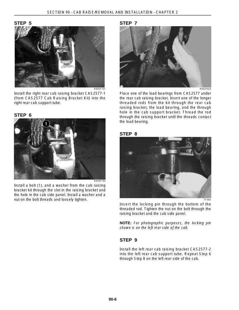
Install the right rear cab raising bracket CAS2577-1(from CAS2577 Cab Raising Bracket Kit) into theright rear cab support tube.
STEP 6
RD02F102
Install a bolt (1), and a washer from the cab raisingbracket kit through the slot in the raising bracket andthe hole in the cab side panel. Install a washer and anut on the bolt threads and loosely tighten.
STEP 7
RD02F025
Place one of the load bearings from CAS2577 underthe rear cab raising bracket. Insert one of the longerthreaded rods from the kit through the rear cabraising bracket, the load bearing, and the throughhole in the cab support bracket. Thread the rodthrough the raising bracket until the threads contactthe load bearing.
STEP 8
77-36X
Insert the locking pin through the bottom of thethreaded rod. Tighten the nut on the bolt through theraising bracket and the cab side panel.
NOTE: For photographic purposes, the locking pinshown is on the left rear side of the cab.
STEP 9
Install the left rear cab raising bracket CAS2577-2into the left rear cab support tube. Repeat Step 6through Step 8 on the left rear side of the cab.
1

SECTION 90 - CAB RAISE/REMOVAL AND INSTALLATION - CHAPTER 2
90-7
STEP 10
76-0A
Install the upper cab raising bracket (1), fromCAS2577 Cab Raising Bracket Kit, into the left frontcab support tube. Install CAS2577-3 lower raisingplate (2) on the front cab mounting bracket, using twoof the bolts from the kit. Place a load bearing on topof the lower raising plate and insert one of the shorterthreaded rods through the upper raising bracket.Thread the rod through the raising bracket until thethreads contact the load bearing. Insert the lockingpin through the bottom of the threaded rod. Repeatthis procedure on the opposite side of the cab.
STEP 11
Turn in the four threaded rods on the cab raisingbrackets in equal amounts to evenly lift the cab.
NOTE: Monitor all lines when raising or lowering thecab to prevent breakage or bending of lines.
12

SECTION 90 - CAB RAISE/REMOVAL AND INSTALLATION - CHAPTER 2
90-8
CAB LOWERING PROCEDURE
STEP 12
75-13
Turn out the four threaded rods on the cab raisingbrackets in equal amounts to evenly lower the cab.Make sure the sleeves on the cab mounting boltsalign with the holes in the cab support tubes. Beginlowering the tractor cab. Check for pinched cables,lines, or hoses. Fully lower the cab.
NOTE: The cab must be evenly lowered. The cabbolt mounting sleeves can bind in the cab supporttube holes, so the cab cannot be lowered.
STEP 13
77-36X
Remove the locking pin from the bottom of thethreaded rod on the rear cab raising tool.
STEP 14
RD02F025
Remove the threaded rod from the raising bracket.Remove the load bearing.
STEP 15
RD02F102
Remove the bolt (1), nut, and the two washers fromthe cab side panel and the slot in the right rearraising bracket. Remove CAS2577-1 r ight rearraising bracket (2). Set the preload on the cabisomounts to a torque of 47 to 61 Nm (35 to 45 lb ft)by holding the square plate and tightening the bolt.
1
2

SECTION 90 - CAB RAISE/REMOVAL AND INSTALLATION - CHAPTER 2
90-9
STEP 16
RD02C146
Install a new nut and the rear cab mount washer.Tighten the nut to a torque of 190 to 244 Nm (140 to180 lb ft). Have an assistant hold the head of the boltunder the cab, if necessary.
STEP 17
Repeat the procedures from Step 13 through Step 16on the left rear side of the cab to remove CAS2577-2cab raising bracket.
STEP 18
76-0A
Remove the locking pin from bottom of the threadedrod on the front cab raising tool. Remove thethreaded rod from the front cab upper raising bracket(1) and remove the bracket. Remove the loadbearing. Detach CAS2577-3 lower raising plate (2)by removing the two bolts. Repeat this procedure onthe opposite side of the cab.
STEP 19
RD02C143
Set the preload on the front cab isomounts to atorque of 47 to 61 Nm (35 to 45 lb ft) by holding thesquare plate and tightening the bolt. Have anassistant hold the head of the bolt, if necessary.Install the front cab mount washer and a new nut.Tighten the nut to a torque of 190 to 244 Nm (140 to180 lb ft) on both sides of the cab. Install the cab floorplug.
STEP 20
76-33
Open the rear window. Install the two bolts securingthe rear cab panel to the cab.
1
2

SECTION 90 - CAB RAISE/REMOVAL AND INSTALLATION - CHAPTER 2
90-10
STEP 21
RD02E069
Install the positive (+) battery cable, first. Install thenegative (-) battery cable. Install the toolbox andbattery cover by tightening the thumbscrews.
STEP 22
RD02C070
Make sure the transmission shift lever is in PARK.Start the engine and lower the rear hitch. Turn theengine off and remove the key. Remove the wheelblocks.

SECTION 90 - CAB RAISE/REMOVAL AND INSTALLATION - CHAPTER 2
90-11
CAB REMOVAL
STEP 23
RD02C070
Park the tractor on a hard, level surface. Put thetransmission shift lever in PARK. Turn off the engineand remove the key. Place blocks in front of andbehind the front wheels. Drain the radiator on a coldengine. Disconnect the negative battery cable first,then the positive cable. Remove the hood. Refer tothe hood removal information in this manual.Properly support the tractor and remove the rearwheels, if necessary.
NOTE: It is not necessary to remove the rearwheels, but may be required to gain enough cabclearance between the tractor chassis and the top ofthe lift.
STEP 24
RD02C074
Identify, tag, and remove the four hydraulic hoses (1)and the steering sensing line (2) from the steeringhand pump. Cap the lines and open fittings.
STEP 25
RD02E061
Remove the throttle linkage.
NOTE: Only on Models TG210 and TG230 tractors.
STEP 26
RD02C162
Identify, tag, and remove the brake valve supply line(1) and return line to sump (2). Cap lines and openfittings.
1
1
2
1
2

SECTION 90 - CAB RAISE/REMOVAL AND INSTALLATION - CHAPTER 2
90-12
STEP 27
RD02C114
Identify, tag, and remove the wiring harnesses fromthe two brake light switches (1) on the brake valve.
STEP 28
RD02B143
Remove the cab heater supply and return lines (1).
STEP 29
RD02C116
Tag the ground cables (1), and disconnect. Removethe cab connector (2) at the right hand front side ofthe cab.
STEP 30
RD02C119
Disconnect the r ight hand cab heater and airconditioning duct hose to move the transmissionwiring harness.
STEP 31
RD02C121
Remove the supply line to the left and right rearbrake.
1
1
1
2

SECTION 90 - CAB RAISE/REMOVAL AND INSTALLATION - CHAPTER 2
90-13
STEP 32
RD02C124
Remove the electr ical connector from the cabpressurization blower.
NOTE: Fuel tank removed for photographicpurposes.
STEP 33
76-33
Open the rear window. Remove the two boltssecuring the rear cab panel to the cab. Remove thepanel.
STEP 34
RD02C128
Remove the cab power cables at the right rear of thecab.
STEP 35
RD02C130
Remove the cab wiring plug at the rear of the cab.
STEP 36
RD02C152
Disconnect the electrical connectors for the rear cablights. Note the position of the four controller moduleson the rear of the cab and unbolt from the cab.Remove the cab rear window washer hose from thenozzle on the left rear fender.
SECTION 90 - CAB RAISE/REMOVAL AND INSTALLATION - CHAPTER 2
90-14
STEP 37
RD02C132
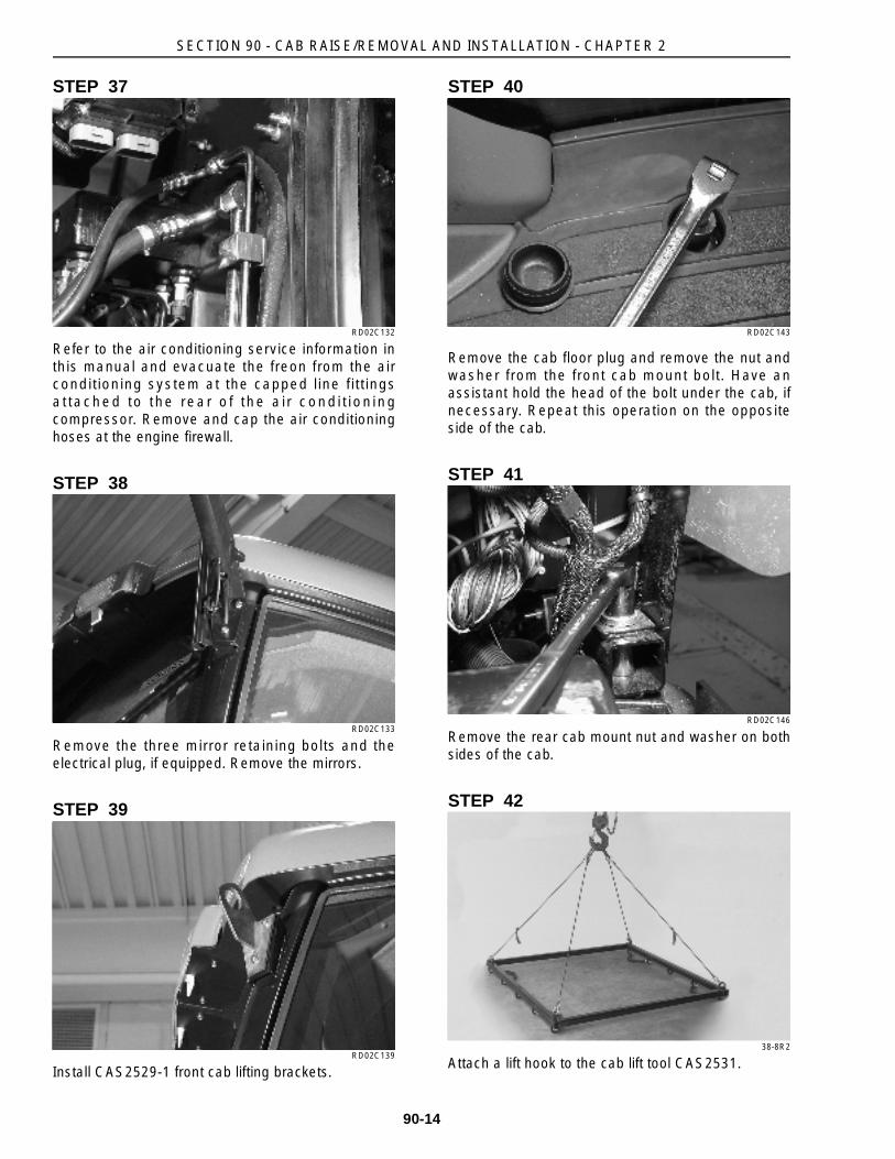
Refer to the air conditioning service information inthis manual and evacuate the freon from the airconditioning system at the capped line fittingsat tached to the rear o f the a i r condi t ion ingcompressor. Remove and cap the air conditioninghoses at the engine firewall.
STEP 38
RD02C133
Remove the three mirror retaining bolts and theelectrical plug, if equipped. Remove the mirrors.
STEP 39
RD02C139
Install CAS2529-1 front cab lifting brackets.
STEP 40
RD02C143
Remove the cab floor plug and remove the nut andwasher from the front cab mount bolt. Have anassistant hold the head of the bolt under the cab, ifnecessary. Repeat this operation on the oppositeside of the cab.
STEP 41
RD02C146
Remove the rear cab mount nut and washer on bothsides of the cab.
STEP 42
38-8R2
Attach a lift hook to the cab lift tool CAS2531.

SECTION 90 - CAB RAISE/REMOVAL AND INSTALLATION - CHAPTER 2
90-15
STEP 43
RD02E271
If equipped, loosen the lower bolt (1), remove theupper bolt (2), and swing the tractor rear warningmarker light down. Finger tighten the upper bolt.Repeat this procedure on the opposite side of thetractor.
STEP 44
RD02E274
Remove the plastic plug from the cab rear windowpost and insert the J-hook from CAS2529-2 rear cablifting bracket into the hole. The hooked end facesdownward. The rear window must be open in order toinsert the J-hook. Install CAS2529-2 rear cab liftingbracket (1). Install 380000707-Left rear cab liftingarm (2) on the left rear side of the cab, as shown.The welded edge of the lifting arm faces toward thecenter of the cab. Tighten the nut. Make sureCAS2529-2 is fully seated on the rear window postand does not have any side movement. Repeat theabove procedure and install 380000706-Right rearcab lifting arm on the right rear side of the cab. InstallCAS2531 cab lifting tool. Make sure the chains onCAS2531 do not bind against the roof or cab lenses.
NOTE: Do not lift the cab until all electrical cables,hydraulic lines, and mechanical parts needed for cabremoval have been tagged and disconnected.
STEP 45
RD02C155
Slightly lift the cab off the chassis. Properly supportthe cab. Remove the hydraulic trailer brake supplylines (if equipped) at the right rear side of the tractor.
STEP 46
RD02C158
Continue lifting the cab and remove it from thetractor. Carefully lower the cab. Properly support thecab by the steel cab rails off the floor to provideclearance for the cab pressurization blower.
2
1
1
2

SECTION 90 - CAB RAISE/REMOVAL AND INSTALLATION - CHAPTER 2
90-16
CAB INSTALLATION
STEP 47
RD02E272
Make sure the chains attached to cab l ift toolCAS2531 do not bind against the roof or cab lenses.Properly support the cab and lower it.
STEP 48
RD02C155
Lower the cab until the hydraulic trailer brake supplylines (if equipped) can be installed at the right rearside of the tractor. Properly support the cab. Tightenthe trailer brake supply lines.
STEP 49
RD02C158
Lower the cab on the tractor chassis, aligning the cabmount bolts with the holes in the cab frame. Checkfor pinched cables, lines, or hoses.
STEP 50
RD02C146
Set the preload on the cab isomounts to a torque of47 to 61 Nm (35 to 45 lb ft) by holding the squareplate and tightening the bolt. Install the rear cabmount washer and tighten the nut to a torque of 190to 244 Nm (140 to 180 lb ft) on both sides of the cab.Have an assistant hold the bolt, if necessary.

SECTION 90 - CAB RAISE/REMOVAL AND INSTALLATION - CHAPTER 2
90-17
STEP 51
RD02C143
Set the preload on the front cab isomounts using theprocedure in the previous step to a torque of 47 to 61Nm (35 to 45 lb ft). Install the front cab mount washerand tighten the nut to a torque of 190 to 244 Nm (140to 180 lb ft) on both sides of the cab.
STEP 52
RD02C139
Remove the cab lifting tool and the front and rear cablifting brackets. Install the plastic plugs in the cabrear window posts.
STEP 53
RD02E271
Remove the upper bolt and swing the tractor rearwarning lights up, if equipped. Install the upper bolt.Tighten the upper and lower bolts.
STEP 54
RD02C133
Install the mirrors and the three mirror retaining bolts.Connect the electrical plug if equipped.
STEP 55
RD02C13
Lubricate new O-rings with refrigerant oil and installon the air conditioning fittings. Install the fittings atthe engine firewall. Recharge the air conditioningsystem with freon at the capped line fittings attachedto the rear of the air conditioning compressor. Referto the air conditioning service information in thismanual.
SECTION 90 - CAB RAISE/REMOVAL AND INSTALLATION - CHAPTER 2
90-18
STEP 56
RD02C126
Install the four controller modules on the rear of thecab. Plug in the connectors for the rear lamps. Installthe cab rear window washer hose to the nozzle onthe left rear fender, if equipped.
STEP 57
RD02C130
Install the cab wiring plug at the rear of the cab.
STEP 58
RD02C128
Install the cab power cables at the right rear of thecab.
STEP 59
76-33
Install the two bolts securing the rear cab panel to thecab.
STEP 60
RD02C124
Instal l the electr ical connector f rom the cabpressurization blower.
NOTE: Fuel tank removed for photographicpurposes.
STEP 61
RD02C121
Install the supply line to the left and right rear brake.

SECTION 90 - CAB RAISE/REMOVAL AND INSTALLATION - CHAPTER 2
90-19
STEP 62
RD02C119
Position the transmission wiring harness and installthe right hand cab heater and air conditioning ducthose.
STEP 63
RD02C116
Using the identification tags from the disassemblyprocedure, install the ground cables (1). Install thecab connector (2) at the right hand front side of thecab.
RD02E061
Connect the throttle linkage.
NOTE: Only on Models TG210 and TG230 tractors.
STEP 64
RD02C162
Use the identification tags to install the brake valvesupply line (1) and return line to sump (2).
STEP 65
RD02C114
Use the identification tags to install the wir ingharnesses on the two brake light switches (1).
STEP 66
RD02B143
Connect the cab heater supply and return lines (1).
1
2
1
2
1
1
SECTION 90 - CAB RAISE/REMOVAL AND INSTALLATION - CHAPTER 2
90-20
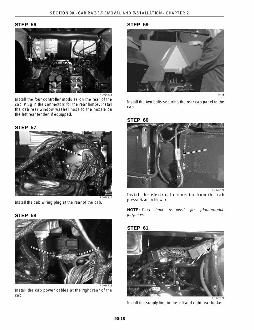
STEP 67
RD02C074
Use the identification tags to install the four hydraulichoses (1) and the steering sensing line (2) on thesteering hand pump.
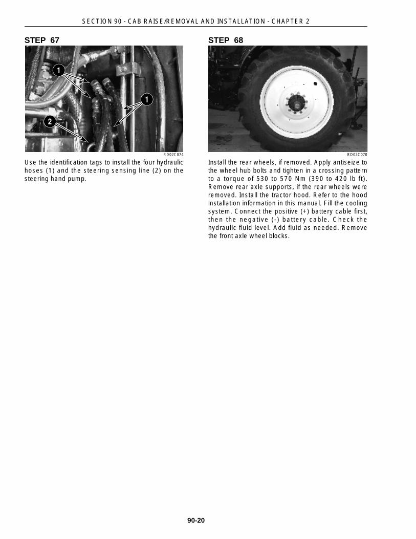
STEP 68
RD02C070
Install the rear wheels, if removed. Apply antiseize tothe wheel hub bolts and tighten in a crossing patternto a torque of 530 to 570 Nm (390 to 420 lb ft).Remove rear axle supports, if the rear wheels wereremoved. Install the tractor hood. Refer to the hoodinstallation information in this manual. Fill the coolingsystem. Connect the positive (+) battery cable first,then the negative (-) battery cable. Check thehydraulic fluid level. Add fluid as needed. Removethe front axle wheel blocks.
1
1
2