Section 8 Pipe Lining Procedures - Polycorp -...
13
RUBBER LINING APPLICATION MANUAL Section 8: Pipe Lining Procedures INNOVATION / QUALITY / SOLUTIONS / TECHNICAL SUPPORT +1-519-846-2075 / +1-800-265-2710 / www.poly-corp.com 1. Metal Specification Pipe should be fabricated and welded in accordance with specific codes. Welds shall have a round and smooth surface suitable for applying rubber lining. 2. Metal Preparation All metal surfaces to be lined should be blasted to a “white-metal” surface defined in SSPC- SP5/NACE No.1. The surface should be free of all oil, grease, dirt, mill scale, rust or other foreign matter. 3. Cementing Apply primer immediately after blasting. Apply additional coats of cements as specified in Technical Data Sheets. Allow sufficient drying time between cement coats as per Section 6. 4. Lining Procedure for Standard Flanged Pipe 4.1 Form a tube with lining stock using longitudinal skived butt seams as illustrated in Fig. 8-1. To facilitate stitching of the skived seam, a metal strip is used inside the tube while it is being formed. The spliced tube’s outside circumference should be slightly less than the inside circumference of the pipe. The following formula is a suggested guideline for cutting width of tubes. Overall Width of Tube = 3 x Pipe ID ** Pipe larger than 16” can be lined with two pieces of stock and joined with laps. Pipe that has a diameter large enough for personnel to enter should be lined in the same manner as tanks or ductwork.
Transcript of Section 8 Pipe Lining Procedures - Polycorp -...

RUBBER LINING APPLICATION MANUAL
Section 8: Pipe Lining Procedures
INNOVATION / QUALITY / SOLUTIONS / TECHNICAL SUPPORT +1-519-846-2075 / +1-800-265-2710 / www.poly-corp.com
1. Metal Specification Pipe should be fabricated and welded in accordance with specific codes. Welds shall have a round and smooth surface suitable for applying rubber lining.
2. Metal Preparation All metal surfaces to be lined should be blasted to a “white-metal” surface defined in SSPC-SP5/NACE No.1. The surface should be free of all oil, grease, dirt, mill scale, rust or other foreign matter.
3. Cementing Apply primer immediately after blasting. Apply additional coats of cements as specified in Technical Data Sheets. Allow sufficient drying time between cement coats as per Section 6.
4. Lining Procedure for Standard Flanged Pipe 4.1 Form a tube with lining stock using longitudinal skived butt seams as illustrated in
Fig. 8-1. To facilitate stitching of the skived seam, a metal strip is used inside the tube while it is being formed. The spliced tube’s outside circumference should be slightly less than the inside circumference of the pipe. The following formula is a suggested guideline for cutting width of tubes.
Overall Width of Tube = 3 x Pipe ID
** Pipe larger than 16” can be lined with two pieces of stock and joined with laps. Pipe that has a diameter large enough for personnel to enter should be lined in the same manner as tanks or ductwork.
RUBBER LINING APPLICATION MANUAL
Section 8: Pipe Lining Procedures
INNOVATION / QUALITY / SOLUTIONS / TECHNICAL SUPPORT +1-519-846-2075 / +1-800-265-2710 / www.poly-corp.com
Fig. 8-1 Longitudinal skived butt splice
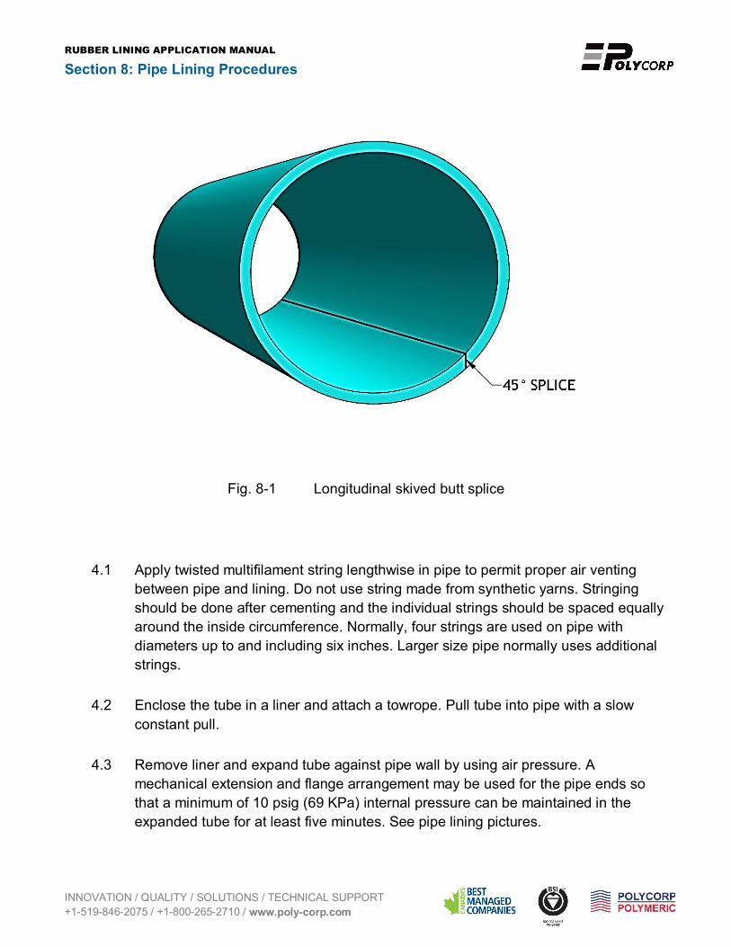
4.1 Apply twisted multifilament string lengthwise in pipe to permit proper air venting between pipe and lining. Do not use string made from synthetic yarns. Stringing should be done after cementing and the individual strings should be spaced equally around the inside circumference. Normally, four strings are used on pipe with diameters up to and including six inches. Larger size pipe normally uses additional strings.
4.2 Enclose the tube in a liner and attach a towrope. Pull tube into pipe with a slow constant pull.
4.3 Remove liner and expand tube against pipe wall by using air pressure. A mechanical extension and flange arrangement may be used for the pipe ends so that a minimum of 10 psig (69 KPa) internal pressure can be maintained in the expanded tube for at least five minutes. See pipe lining pictures.

RUBBER LINING APPLICATION MANUAL
Section 8: Pipe Lining Procedures
INNOVATION / QUALITY / SOLUTIONS / TECHNICAL SUPPORT +1-519-846-2075 / +1-800-265-2710 / www.poly-corp.com
4.4 Remove extension and flare excess stock over flange face and trim flush.
4.5 Apply a covering to full face of flange. Remove extension of pipe lining and fold the edges over the flange face mating up to the flange rubber with a closed skive. See Fig. 8-2-1 and Fig. 8-2-2.
** When using hard rubber lining on flanges, it is important that customer understands that soft rubber gaskets are required over the face lining.
4.6 On pipe sizes larger than 6”, the flange stock may be lapped onto the pipe lining with a closed skive instead of the skive used on smaller size. This lapping technique makes a stronger joint and is the preferred method. Some customers may prefer not to have laps at flanges because of abrasion considerations or requirements on full line capacity. See Fig. 8-3-1 and Fig. 8-3-2.
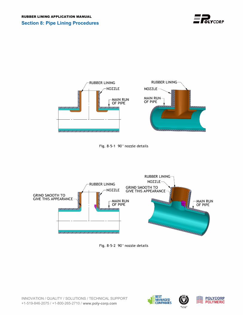
4.7 Fig. 8-4 and Fig. 8-5 for suggested lining styles of lateral nozzles and side outlets.

RUBBER LINING APPLICATION MANUAL
Section 8: Pipe Lining Procedures
INNOVATION / QUALITY / SOLUTIONS / TECHNICAL SUPPORT +1-519-846-2075 / +1-800-265-2710 / www.poly-corp.com

RUBBER LINING APPLICATION MANUAL
Section 8: Pipe Lining Procedures
INNOVATION / QUALITY / SOLUTIONS / TECHNICAL SUPPORT +1-519-846-2075 / +1-800-265-2710 / www.poly-corp.com

RUBBER LINING APPLICATION MANUAL
Section 8: Pipe Lining Procedures
INNOVATION / QUALITY / SOLUTIONS / TECHNICAL SUPPORT +1-519-846-2075 / +1-800-265-2710 / www.poly-corp.com
RUBBER LINING APPLICATION MANUAL
Section 8: Pipe Lining Procedures
INNOVATION / QUALITY / SOLUTIONS / TECHNICAL SUPPORT +1-519-846-2075 / +1-800-265-2710 / www.poly-corp.com

RUBBER LINING APPLICATION MANUAL
Section 8: Pipe Lining Procedures
INNOVATION / QUALITY / SOLUTIONS / TECHNICAL SUPPORT +1-519-846-2075 / +1-800-265-2710 / www.poly-corp.com
Lining Procedure for Victaulic Pipe 5.1 Line inside of pipe in accordance with procedures used for standard flanged pipe.
5.2 When using 1/8” through 1/4” linings the tube lining should be extended over the end of the pipe and bent back into the recess on the outside of the pipe. Apply a round of tape over the OD of outside rubber. After cure, remove the tape and buff the OD flush with OD of metal. See Fig. 8-6-1 and Fig. 8-6-2 for rubber lining constructions including single grooved pipe and double grooved pipe for Victaulic pipe.

RUBBER LINING APPLICATION MANUAL
Section 8: Pipe Lining Procedures
INNOVATION / QUALITY / SOLUTIONS / TECHNICAL SUPPORT +1-519-846-2075 / +1-800-265-2710 / www.poly-corp.com

RUBBER LINING APPLICATION MANUAL
Section 8: Pipe Lining Procedures
INNOVATION / QUALITY / SOLUTIONS / TECHNICAL SUPPORT +1-519-846-2075 / +1-800-265-2710 / www.poly-corp.com
PIPE LINING PROCEDURE
1, Cutting a rectange rubber sheet 2, Applying cement (or solvent)
3, Forming a tube 4, Stitching of the skived seam

RUBBER LINING APPLICATION MANUAL
Section 8: Pipe Lining Procedures
INNOVATION / QUALITY / SOLUTIONS / TECHNICAL SUPPORT +1-519-846-2075 / +1-800-265-2710 / www.poly-corp.com
5, Applying solvent on the tube 6, Wrapping the tube with Cloth Liner
7, Stringing pipe 8, Pulling Tube through pipe with Cloth Liner

RUBBER LINING APPLICATION MANUAL
Section 8: Pipe Lining Procedures
INNOVATION / QUALITY / SOLUTIONS / TECHNICAL SUPPORT +1-519-846-2075 / +1-800-265-2710 / www.poly-corp.com
9, Removing the Cloth Liner 10, Expanding the tube against pipe wall
11, Flaring Tube over face of flange 12, Cutting out flange stock

RUBBER LINING APPLICATION MANUAL
Section 8: Pipe Lining Procedures
INNOVATION / QUALITY / SOLUTIONS / TECHNICAL SUPPORT +1-519-846-2075 / +1-800-265-2710 / www.poly-corp.com
13, Applying solvent to Flange cover 14, Placing Flange cover to Flange face
15, Stitching Flange unit 16, Cutting rubber out of bolt holes