SECTION 8: HVAC SENSORS - Thermo Cense · 2018-01-03 · TT321: Fixed Range (3 leads) Contact for...
19
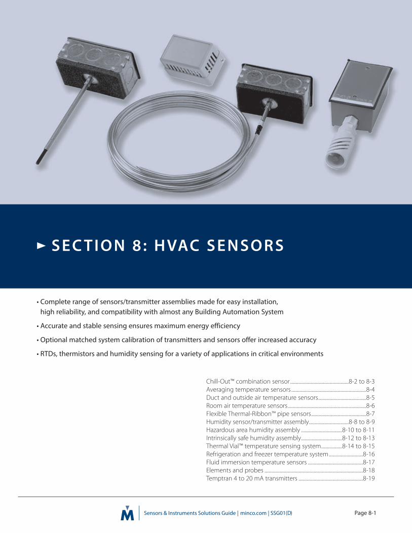
Page 8-1 • Complete range of sensors/transmitter assemblies made for easy installation, high reliability, and compatibility with almost any Building Automation System • Accurate and stable sensing ensures maximum energy efficiency • Optional matched system calibration of transmitters and sensors offer increased accuracy • RTDs, thermistors and humidity sensing for a variety of applications in critical environments Chill-Out™ combination sensor ..................................................8-2 to 8-3 Averaging temperature sensors ................................................................8-4 Duct and outside air temperature sensors.........................................8-5 Room air temperature sensors ...................................................................8-6 Flexible Thermal-Ribbon™ pipe sensors...............................................8-7 Humidity sensor/transmitter assembly..................................8-8 to 8-9 Hazardous area humidity assembly ...................................8-10 to 8-11 Intrinsically safe humidity assembly...................................8-12 to 8-13 Thermal Vial™ temperature sensing system..................8-14 to 8-15 Refrigeration and freezer temperature system .............................8-16 Fluid immersion temperature sensors ...............................................8-17 Elements and probes ....................................................................................8-18 Temptran 4 to 20 mA transmitters .......................................................8-19 SECTION 8: HVAC SENSORS
Transcript of SECTION 8: HVAC SENSORS - Thermo Cense · 2018-01-03 · TT321: Fixed Range (3 leads) Contact for...
Page 8-1
• Complete range of sensors/transmitter assemblies made for easy installation, high reliability, and compatibility with almost any Building Automation System
• Accurate and stable sensing ensures maximum energy efficiency
• Optional matched system calibration of transmitters and sensors offer increased accuracy
• RTDs, thermistors and humidity sensing for a variety of applications in critical environments
Chill-Out™ combination sensor..................................................8-2 to 8-3Averaging temperature sensors ................................................................8-4Duct and outside air temperature sensors.........................................8-5Room air temperature sensors...................................................................8-6Flexible Thermal-Ribbon™ pipe sensors...............................................8-7Humidity sensor/transmitter assembly..................................8-8 to 8-9Hazardous area humidity assembly ...................................8-10 to 8-11Intrinsically safe humidity assembly...................................8-12 to 8-13Thermal Vial™ temperature sensing system..................8-14 to 8-15Refrigeration and freezer temperature system.............................8-16Fluid immersion temperature sensors ...............................................8-17Elements and probes ....................................................................................8-18Temptran 4 to 20 mA transmitters .......................................................8-19
S E C T I O N 8 : H VAC S E N S O R S

Page 8-2
Specifications subject to change= STANDARD OPTIONS
ChillOutTM Combination Sensor
Specification and order options
Overview
• Two sensors in one easily installed package: a solid state lowtemperature cut-out ("Freeze Stat") and an averaging resistancetemperature sensor.
• Digital alarm signal to RTU, PLC or an electronic control; 24VAC-powered.
• Solid state design and rugged 3/8" diameter tubing eliminate concerns of gas leaks or kinking the capillary during installation.
• Mount in any direction — horizontal installation is not required.
• Easily formed aluminum or ultra flexible plenum-rated PVC coatedgalvanized steel armor sensor case.
• Relay and control circuitry self contained in rugged housing.Mounts on either side of enclosure with a locknut (included).
• Failure detection feature — relay changes state if power is lost
• 4 to 20 mA temperature loop output available with optionalTemptran™ (ordered separately — see Section 4 for more information)
Specifications
Switching temperature: 38°F factory pre-set, user adjustable from30°F to 44°F.
Accuracy: ±0.9°F (±0.5°C) typical.
Power requirement: 24V AC or DC.
Relay contact: User specified Standard relay, SPDT (2" x 4" utility box)
0.3 A at 125 VAC, Max. Voltage 125 VAC, or1A at 30 VDC, Max. Voltage 110 VDC
Optional power relay, DPST (4" x 4" utility box)25 A at 277 VAC25 A at 120 VAC1 HP at 120 VAC2 HP at 277 VAC
Sensor case length: 10 feet standard, lengths up to 50 feet available by special order.
Connection: AWG 18 leadwires.
Bendable Aluminum
Chill-Out Sensor installation example
Ultra Flexible PVC CoatedSteel Armor
AS103759 Model number
PF Element Type:PF = 1000 Ω RTD (0.00385 Platinum)
38 Switching Temperature: 38°FSpecify 30 to 44°F
E Relay reset option:N = Non-latching (auto reset)L = Latching (manual reset)E = Latching (panel mounted reset)
Note: option ‘E’ requires enclosure ‘L’
10 Case length: 10 feet: 10, 24, 50
A Case type:A = AluminumB = PVC
1 Relay Rating:1 = 0.3A2 = 25A, VAC powered controller/coil3 = 25A, VDC powered controller/coil
Note: option 2 or 3 requires enclosure ‘L’
L Enclosure:N = No enclosureS = Standard utility box (2” x 4”)L = Large utility box (4” x 4”)W = Weatherproof utility box (2” x 4”)
AS103759PF38E10A1L = Sample part number
Order Replacement Relays
Model number External Relay
AC103779 25A24VAC Coil
AC103780 25A24VDC Coil

Page 8-3
Specifications subject to change= STANDARD OPTIONS
HV
AC
SE
NS
OR
S
34°F
38°F
44°F
36°F
42°F32°F
40°F
30°F
¾ - 14 NPSM
Ø .375
2.0 REF L ± .5 FT
2.0 REF L ± .5 FT
¾ - 14 NPSM
Ø .375
Standard and Large Utility Boxes
Weatherproof Utility Box
Ø .375
2.5 REF 10.0 FT ± .5 FT
¾ - 14 NPSM (Z)
No Enclosure
ALARM OUTPUT, NO [ORANGE]
24VAC (H) [WHITE]24VAC (N) [BLACK]
RESET SWITCH (OPTIONAL)
TEMPERATURE SENSOR [RED]TEMPERATURE SENSOR [RED]
ALARM OUTPUT, NC [BLUE]
SET POINT ADJUSTMENT
LED
0
2468
24 VACor
24 VDC
110VAC
NEUTRAL
110 VAC OUTPUT (H)
110 VAC OUTPUT(N)
NEUTRAL
HOT
HOT
HOT
Typical Installation with Relay
Setpoint Adjustment
ALARM OUTPUT [ORANGE](NO CONTACT, CLOSES WHEN POWER APPLIED)
ALARM OUTPUT [BLUE](NC CONTACT, OPENS WHEN POWER APPLIED)
24VAC (COM) [BLACK]
24VAC [WHITE]
TEMPERATURE SENSOR [RED]
TEMPERATURE SENSOR [RED]
RESET SWITCH (OPTIONAL)LED
SET POINT ADJUSTMENT
Chill-Out Sensor Interface

Specifications subject to change
Page 8-4
= STANDARD OPTIONS
Averaging Temperature SensorsOverview
Sense temperature of air streams in ducts and plenums.Sensors include a junction box with gasket to prevent leakageand vibration noise.
These sensors have a continuous element to sense trueaverage temperature along their entire length. They provideaccurate composite readings in locations where air may bestratified into hot and cold layers.
Rigid averaging sensors have a brass case. Bendable modelshave aluminum sheaths (copper on special order), formable toa radius of 4". Bendable sensors can criss-cross ducts to averagetemperatures in two dimensions.
See page 4-2 for optional 4 to 20 mA temperature transmitters.
Specifications
Temperature range:
Probe: -45.5 to 135°C (-50 to 275°F).Gasket: 100°C (212°F) max.
Leadwires: AWG 22, PTFE insulated, 8" (200 mm) long.
Moisture resistance: Meet MIL-STD-202, Method 104, TestCondition B.
Special options:
• Lengths to 100 feet(30 m) • Weatherproof connection box
• Sensor only, no box • Thermistor averaging sensors
Specification and order options:
Rigid averaging sensors
Bendable averaging sensors
To order with transmitter, add
RTDs(Tolerance: ±0.25% at 70°F)
TCRΩ/Ω/°C
Rigid averagingsensors
Bendable averagingsensors
*Platinum 100 Ω at 0°C 0.00391 S423PB S447PB *Platinum 100 Ω at 0°C 0.00385 S456PE S457PE *Platinum 1000 Ω at 0°C 0.00385 S493PF S475PF *Platinum 1000 Ω at 0°C 0.00375 S492PW S488PW Nickel-iron 1000 Ω at 70°F 0.00527 S421FB S445FB Nickel-iron 2000 Ω at 70°F 0.00527 S422FC S446FC *HW 3000 Ω at -30.2°C 0.00262 S20080PX S15215PX
Rigid
Averaging Sensor
Enclosure:W 2.12" (54 mm)H 4.00" (102 mm)D 1.75" (44 mm)
Sheath Diameter:0.188" (4.8 mm)
Bendable
Averaging Sensor
Enclosure:W 2.12" (54 mm)H 4.00" (102 mm)D 1.75" (44 mm)
Sheath Diameter:0.188" (4.8 mm)
S456PE Model number from table
Y Number of leads:Y = 2 leadsZ = 3 leads
12 Insertion depth in inches:1 inch = 25.4 mm: 12, 24, 48
S456PEY12 = Sample part number
S457PE Model number from table
Z Number of leads:Y = 2 leadsZ = 3 leads
24 Insertion length in feet:1 foot = 0.3 m: 12, 24, 50, 100
S457PEZ24 = Sample part number
Model numbers
* These averaging sensors use a proprietary sensing element that closely matches the platinum curve over the specified range.
STOCKED PARTS AVAILABLE
TT111 Transmitter ModelsTT111: Fixed Range (2 leads)TT211: Fixed Range (2 leads)TT321: Fixed Range (3 leads)Contact for other transmitter options.
A Temperature Range Code:A = 20°F to 120°F (-6.7°C to 48.9°C)Contact for complete list of available temp. codes.
1 Calibration:1 = Nominal Calibration2 = Match Calibrated,
0.75% Total System AccuracyContact for other calibration options.
TT111A1 = Sample part number addition

Page 8-5
Specifications subject to change
HV
AC
SE
NS
OR
S
Overview
Sense temperature of air streams in ducts and plenums. Sensors include a junction box with gasket to prevent leakage and vibration noise.
These point-sensing thermometers feature a fast-respondingaluminum sensing tip.
Custom options include a weatherproof connection box and anall stainless steel probe.
Outside air sensors are designed to mount on conduit outside yourbuilding. They include an elbow type enclosure and sun shield.
See page 4-2 for optional 4 to 20 mA temperature transmitters.
Specifications
Temperature range:
Probe: -45.5 to 135°C (-50 to 275°F).Gasket: 100°C (212°F) max.
Leadwires:
AWG 22, PTFE insulated, 4" (100 mm) long.
Moisture resistance:
Point sensors meet MIL-STD-202, Method 104, Test Condition B
Special options
• Weatherproof connection box
• All stainless steel probe
Specification and order options:
Duct point sensors
Outside air sensors
To order with transmitter, add
Probe Diameter:0.25" (6.4 mm)0.188" (4.8 mm) at tip
Outside Air Sensor
Dimensions:L 5.6" (142 mm)H 1.6" (41 mm)W 1.3" (33 mm)
Duct and Outside Air Temperature Sensors
Element TCRΩ /Ω/°C
Duct point sensors
Outside air sensors
RTDs
Platinum 100 Ω ±0.1% at 0°C 0.00391 S408PB S414PBPlatinum 100 Ω ±0.1% at 0°C
(Meets EN60751, Class B)0.00385 S450PD S454PD
Platinum 1000 Ω ±0.1% at 0°C 0.00385 S451PF S455PF Platinum 1000 Ω ±0.1% at 0°C 0.00375 S484PW S486PW Nickel-iron 1000 Ω ±0.12% at 70°F 0.00527 S406FB S412FB Nickel-iron 2000 Ω ±0.12% at 70°F 0.00527 S407FC S413FC HW 3000 Ω at -30.2°C 0.00262 S100060PX S100062PXThermistors R25¼R125
Thermistor 2,252 Ω ±1% at 25°C 29.2 TS430TA TS428TA Thermistor 10,000 Ω ±1% at 25°C 23.5 TS431TB TS429TB
S450PD Model number from table
Y Number of leads:Y = 2 leadsZ = 3 leads (RTD only)
12 Insertion depth in inches:1 inch = 25.4 mm: 6, 12, 18"Minimum: 3"
S450PDY12 = Sample part number
S414PB Model number from table
Z Number of leads:Y = 2 leadsZ = 3 leads (RTD only)
S414PBZ = Sample part number
Model numbers
Duct Point Sensor
Enclosure:W 2.12" (54 mm)H 4.00" (102 mm)D 1.75" (44 mm)
TT111 Transmitter ModelsTT111: Fixed Range (2 leads)TT211: Fixed Range (2 leads)TT321: Fixed Range (3 leads)Contact for other transmitter options.
A Temperature Range Code:A = 20°F to 120°F (-6.7°C to 48.9°C)Contact for complete list of available temp. codes.
1 Calibration:1 = Nominal Calibration2 = Match Calibrated,
0.75% Total System Accuracy3 = Match Calibrated,
0.5% Total System Accuracy4 = Match Calibrated,
0.2% or 1°C Total System AccuracyContact for other calibration options.
TT111A1 = Sample part number addition
STOCKED PARTS AVAILABLE

Compact Wall-mount
Dimensions:W 3.12" (79 mm)H 2.09" (54 mm)D 1.80" (46 mm)
Full Size Wall-mount
Dimensions:W 2.75" (70 mm)H 4.50" (114 mm)D 1.56" (40 mm)
Explosionproof Wall-
mount
Dimensions:W 1.60" (41 mm)H 5.55" (141 mm)D 2.05" (52 mm)
Flush Wall-mount
Dimensions:W 2.75" (70 mm)H 4.50" (114 mm)D 0.18" (5 mm)
Overview
Minco’s room air sensors are available with a variety of enclo-sures that meet most standard and explosionproof HVAC/Rinstallations. The sensors can be match calibrated with a MincoTemptran™ (temperature transmitter) for increased accuracyand reliability.
Room air sensors are designed for wall mounting. Choose fromtwo plastic enclosure styles with brushed aluminum faceplatesor a flushmount stainless steel model.
The full-size enclosure and flushmount fit over standard junction boxes. The full size enclosure has optional knockouts for Wiremold raceway surface wiring. Just remove knockouts with pliers. This enclosure may also include a 4-20 mA temperature transmitter; specify model AS200655.
The compact room air sensor mounts directly on drywall.
The explosionproof sensor housing is UL listed and CSA approved for Class I, GroupsC and D; Class II, Groups E, F, and G; and
Class III. Download Application Aid #19 for more hazardous area information and the various standards and agencies (including FM, CSA, CENELEC and ATEX) atwww.minco.com.
Specifications
Temperature range:
-45.5 to 100°C (-50 to 212°F)
Temperature range (with TT115 transmitter):
Zero: -40 to 10°C (-40 to 50°F)Span: 25 to 100°C (45 to 180°F)Max upper temperature: 85°C (185°F)
Leadwires:
Full size and compact: AWG 22, PTFE insulated, 4" (100 mm) long.
Explosionproof and flush mount: AWG 26, PTFE insulated, 6" (150 mm) inside cover.
Page 8-6
Room Air Temperature Sensors
S472PB Model number from tableY Number of leads:
Y = 2 leads Z = 3 leads4 Lead length in inches: : 4K0 Knockouts (full size only):
K0= No knockoutsK1= Knockouts for wiremold raceway
S472PBY4K0 = Sample part number
S100147PD Model number from tableY Number of leads:
Y = 2 leads Z = 3 leadsS100147PDY = Sample part number
Compact and full size
Note: For replacement cover only, order part AC692KO orAC692K1 for full size, AC551 for compact.
Explosionproof and flush-mount
Specification and order options:
Element TCRΩ /Ω/°C
Compactroom airsensors
Full sizeroom airsensors
Explosion-proof wall-mountsensors
Flushmountroom air sensors
RTDsPlatinum100 Ω ±0.1% at 0°C
0.00391 S405PB S472PB
Platinum100 Ω±0.1% at 0°C(Meets EN60751, Class B)
0.00385 S448PD S473PD S100147PD S101456PD
Platinum1000 Ω ±0.1% at 0°C
0.00385 S449PF S474PF S100148PF S101456PF
Platinum1000 Ω ±0.1% at 0°C
0.00375 S483PW S489PW S101608PW S101456PW
Nickel-iron1000 Ω ±0.12% at 70°F
0.00527 S403FB S470FB
Nickel-iron2000 Ω ±0.12% at 70°F
0.00527 S404FC S471FC
HW3000 Ω at -30.2°C
0.00262 S1000064PX S1000063PX
Thermistors R25¼R125
Thermistor2,252 Ω ±1% at 25°C
29.2 TS426TA TS424TA TS100149TA TS101769TA
Thermistor10,000 Ω ±1% at 25°C
23.5 TS427TB TS425TB TS100150TB TS101769TB
Moisture resistance: Meets MIL-STD-202, Method 104, Test Condition B.
Transmitters: Full size sensors with 2 leads can useTemptran™ transmitter model TT115 installed withinthe sensor enclosure. A variety of transmitters areavailable for all other sensor models. Transmitters mustbe installed in a separate enclosure from the sensor.
STOCKED PARTS AVAILABLE

Flexible ThermalRibbon™ Pipe Sensors
Note: Tape the Thermal-Ribbon in place beneath a layer of insulation.
Page 8-7
Specifications subject to change= STANDARD OPTIONS
HV
AC
SE
NS
OR
S
Overview
Flexible Thermal-Ribbon™ sensors mount on the pipe surfaceso there’s no expense of a pipefitter to drain, drill, and tap thepipe for a thermowell because there is no thermowell! Whenproperly installed and insulated, the accuracy and response ofa Thermal-Ribbon equals an immersed thermowell assembly.
Options include stainless steel braid over leadwires to preventabrasion damage and pressure-sensitive adhesive for easiermounting (smooth surfaces only).
See Section 4 for optional 4 to 20 mA temperature transmitters.
Specification and order options
S467PD Model number from table
Z Number of leads:Y = 2 leadsZ = 3 leads (RTD only)YS = 2 leads, stainless steel braidZS = 3 leads, stainless steel braid (RTD only)
36 Lead length in inches
A Adhesive backing:A = No adhesiveB = Pressure-sensitive adhesive
S467PDZ36A = Sample part number
Element TCR Ω /Ω/°C ModelRTDsPlatinum 100 Ω ±0.1% at 0°C 0.00391 S464PBPlatinum 100 Ω ±0.1% at 0°C
(Meets EN60751, Class B)0.00385 S467PD
Platinum 1000 Ω ±0.1% at 0°C 0.00385 S468PFNickel-iron 1000 Ω ±0.12% at 70°F 0.00527 S462FB Nickel-iron 2000 Ω ±0.12% at 70°F 0.00527 S463FCHW 3000 Ω at -30.2°C 0.00262 S100001PXThermistors R25/R125
Thermistor 2,252 Ω ±1% at 25°C 29.2 TS436TAThermistor 10,000 Ω ±1% at 25°C 23.5 TS437TB
Mounting accessories:
AC766 mounting kit
Provides a pipe-mounted enclosure for transmitters and connections. Kit includes junction box, 5 ft. nylon strap, buckle, 4 wire nuts, and 6 ft. of #20 stretch tape.
#20 stretch tape
High temperature self-fusing silicone rubber tape for mountingThermal-Ribbons to pipes. 1" wide rolls, 6 or 36 foot lengths.
#6 RTV adhesive
Room temperature vulcanizing adhesive for attaching Thermal-Ribbons to surfaces. 3 oz. (89 ml) tube.
Specifications
Body material: Silicone rubber with polyimide backing.
Temperature range:
RTD: -62 to 200°C (-80 to 392°F).Thermistor: -45.5 to 135°C (-50 to 275°F).
Leadwires: AWG 24, silicone rubber.
Moisture resistance: Meets MIL-STD-202, Method 104, Test Condition B.
Model numbers
STOCKED PARTS AVAILABLE

Page 8-8
Specifications subject to change= STANDARD OPTIONS
Overview
Minco humidity and humidity/temperature transmitters aredesigned using an advanced microprocessor. Digital signalprocessing allows these transmitters to precisely match thecharacteristics of the humidity sensor to a wide range of RHand temperature values found in the many applications theproduct serves.
The humidity sensor is composed of an integrated circuit (IC)with a stable polymer element and platinum RTD that is used fortemperature compensation. This sensor offers outstanding resist-ance to airborne contaminant and chemicals, and is protectedby a sintered stainless steel filter which resists condensation.
• Wall/Duct/OSA mounting configurations
• Accuracies of ±1% or ±2% RH
• Temperature compensated
• Temperature output option
• Two-point field calibration
• NIST traceable calibrations
Applications
Building environmental control systems (HVAC), hospitals, foodstorage, warehouses, clean rooms, pharmaceutical, freezers,drying equipment, and emissions monitoring.
Specifications
Ambient Temperature:
Operating:Room: -10 to 150°F (-23 to 65°C), non-condensing.Wall/Duct/OSA: -10 to 185°F (-23 to 85°C), non-condensing.
Storage:Room: -58 to 150°F (-50 to 65°C), non-condensing.Wall/Duct/OSA: -58 to 185°F (-50 to 85°C), non-condensing.
Supply voltage: 9.5 to 35 VDC, non-polarized.
Voltage effect: ±.001% of span/volt from 9.5 to 35 VDC.
Loop resistance: The maximum allowable resistance of the signal-carrying loop, including extension wires and load resis-tors, is given by this formula: Rloopmax = (Vsupply - 9.5)/0.02 AMPS.For example, if supply voltage is 24 VDC, the loop resistancemust be less than 725 Ω.
Adjustments: Zero and span field adjustments, non-interacting.
Time Constant: 50 seconds in slow moving air.
Connections: Screw terminals (22-14 AWG wire).
Weight:
Room: 0.19 lb (.084 kg).Wall/Duct/OSA: 1.20 lb (0.55 kg).
Minimum output current: 3.5 mA
Maximum output current: 23 mA.
Humidity Sensor/Transmitter Assembly
Wall/Duct
Space
Outside Air (OSA)

Page 8-9
Specifications subject to change= STANDARD OPTIONS
HV
AC
SE
NS
OR
S
Humidity Transmitter AH429 and AH439
Output: 4-20 mA DC = 0% to 100% RH.
Sensing Element: Capacitive monolithic IC.
Accuracy: Includes temperature, linearity, hysteresis, andrepeatability.
±1% from 10% to 80% RH @ 25 to 35°C or±2% from 0% to 90% RH @ 25°C
(±3% from 0% to 90% RH @ 15 to 50°C)(±5% from 0% to 90% RH @ 0 to 82°C)
Temperature Transmitter (AH439 only)
Output: 4-20 mA DC over the specified temperature range.
Sensing element: 1000 Ω platinum; 2 lead resistance thermometer, 0.00385 TCR.
Accuracy: Includes resistance thermometer tolerance, calibra-tion accuracy, linearity, and ambient temperature effects.
±.75% of Temptran™ span for 32 to 122°F ambient.±1.50% of Temptran™ span for -13 to 185°F ambient.
AH429 = Humidity Transmitter
AH439 = Humidity/Temperature Transmitter
AH429 Specification and order options
AH429 Model number:R Enclosure
D: Duct mount, 8" probe lengthO: Outside Air/Wall mount, 4" probe length
with shield, weather resistant enclosureS: Space mountW: Wall mount, 4" probe length, weather
resistant enclosureR: Remote probe, 4" probe length
1 Output: 4 to 20 mA DCN10 Calibration accuracy (humidity transmitter)
N10: ±1% from 10% to 80% (25 to 35°C) with NIST certificate
N20: ±2% from 0% to 90% (25 to 35°C) with NIST certificate
S20: ±2% from 0% to 90% (25 to 35°C)T1 Sensing element cover
(omitted on "S" space mount models)T0= Sintered stainless steel; pressed on coverT1= Sintered stainless steel; screw on coverT2= Slotted stainless steel; screw on cover
(NA on "O" outside air models)To order enclosure D, O, S or W, stop here.To order enclosure R (remote probe), add:A Probe mounting location
A = Side mounting B = Bottom mounting48 Remote probe cable length (in inches)
48" and 96" are standard lengthsAH429R1N10T1A48 = Sample part number
AH439 Model number:D Enclosure
D: Duct mount, 8" probe lengthO: Outside Air/Wall mount, 4" probe length
with shield, weather resistant enclosureS: Space mountW: Wall mount, 4" probe length, weather
resistant enclosureR: Remote probe, 4" probe length
1 Outputs: 4 to 20 mA DCN10 Calibration accuracy (humidity transmitter)
N10: ±1% from 10% to 80% (25 to 35°C) with NIST certificate
N20: ±2% from 0% to 90% (25 to 35°C) with NIST certificate
S20: ±2% from 0% to 90% (25 to 35°C)A Temperature transmitter range
EN: -20°F to 140°FS: 0°F to 100°FA: 20°F to 120°FBI: 30°F to 130°FKK: 30°F to 180°FN: 32°F to 122°FH: 40°F to 90°FMore temperature range codes starting on page 4-20 or www.minco.com
T1 Sensing element cover (omitted on “S” space mount models)T0= Sintered stainless steel; pressed on coverT1= Sintered stainless steel; screw on coverT2= Slotted stainless steel; screw on cover
(NA on "O" outside air models)To order enclosure D, O, S or W, stop here.To order enclosure R (remote probe), add:
A Probe mounting locationA = Side mounting B = Bottom mounting
48 Remote probe cable length (in inches)48" and 96" are standard lengths
AH439D1N10AT1A48 = Sample part number
AH439 Specification and order options

Page 8-10
Specifications subject to change= STANDARD OPTIONS
Overview
Models AH71_, AH72_, and AH73_ series are 2-wire tempera-ture compensated humidity transmitters that are FM and CFMapproved for use in hazardous locations. Intrinsically safe mod-els are available with an optional temperature transmitter out-put. The AH73 is also available with an optional digital displayfor remote indication of relative humidity and temperature.
The transmitters utilize a thin film capacitive humidity sensorwhich provides outstanding sensitivity and chemical robustness.The transmitter converts the humidity sensor’s signal into a 4 to20 mA DC current, which changes proportionally from 4 mA at0% RH to 20 mA at 100% RH. The optional temperature loopproduces a second 4 to 20 mA DC output where the currentchanges from 4 mA at the lowest temperature of the range, to20 mA at the top of the temperature range. The leads that supply power also carry the current signal.
• Accuracy of ±2.5% RH
• Temperature compensated
• Temperature output option
• Two-point field calibration
• NIST traceable calibrations
Applications
Building automation systems (HVAC), hospitals, food storage,warehouses, clean rooms, pharmaceutical, drying equipment,and emissions monitoring.
Specifications
Output(s):
Humidity: 4 to 20 mA DC = 0% to 100% RH.Temperature: 4 to 20 mA DC over specified range (optional)
Humidity Range: 0 – 100% RH
Sensing Element:
Humidity: Thin film capacitive element.Temperature: 1000 ohm platinum RTD, 0.00385 TCR
Temperature Effect: ±0.03% RH/°C ±1% from 10°C to 85°C
Operating Temperature:
Transmitter:-40 to 176°F (-40 to 80°C), non-condensing.
-4 to 176°F (-20 to 80°C), non-condensing, model AH73.Sensor:
-40 to 302°F (-40 to 150°C).
Storage Temperature:
-58 to 185°F (-50 to 85°C), non-condensing.
Supply voltage:
9.5 to 28 VDC for intrinsically safe (IS) models.16.5 to 28 VDC for explosionproof (XP) models.
Voltage effect: ±0.001% of span/volt from 9.5 to 28 VDC.
Loop resistance: The maximum allowable resistance of the signal-carrying loop, including extension wires and load resistors, is given by this formula: IS: Rloopmax = (Vsupply - 9.5)/0.02 AMPS. For example, if supply volt-age is 24 VDC, the loop resistance must be less than 725 Ω.XP: Rloopmax = (Vsupply - 16.5)/0.02 AMPS. For example, if supplyvoltage is 24 VDC, the loop resistance must be less than 375 Ω.
Hazardous Area Humidity Assembly
Page 8-11
Specifications subject to change= STANDARD OPTIONS
HV
AC
SE
NS
OR
S
Accuracy: Includes linearity, hysteresis, repeatability, and voltage effects.Humidity: ±2.5% from 10% to 80% RH @ 25°C, ±3.5% from
80% to 90% RH @ 25°C.Temperature: ±0.5°F(0.27°C) @ 77°F (25°C) or +/- 0.75% of span,
whichever is greater.
Adjustments: Zero and Span field adjustments, non-interacting.
Time Constant: 50 seconds in slow moving air.
Connections: Screw terminals (22-14 AWG wire).
Weight:
AH71_ 2.84 lbs (1.29 kg).AH72_, AH73_ 4.46 lbs (2.02 kg).
Min. output current: 3.8 mA.
Max. output current: 22 mA.
Filter: 60 micron stainless-steel sintered filter(replacement P/N : AC103512)
Factory Mutual Approvals:
Explosionproof with intrinsically safe sensor: Suitable for the following hazardous area locations: Class I, Division 1, 2, Groups B, C, DClass II, Division 1, 2, Groups E, F, GClass III, Division 1, 2
Intrinsically safe installation: Suitable for the following hazardous area locations: Class I, Division 1, 2, Groups A, B, C, DClass II, Division 1, 2, Groups E, F, GClass III, Division 1, 2Class I, Zone 0, AEx ia IIC T4
Non-Incendive: Suitable for the following hazardous area locations: Class I, Division 2, Groups A, B, C, DClass II, Division 2, Groups F, GClass III, Division 2
Transmitter entity parameters:
Vmax = 28 volts; Imax = 100 mA; Ci = 0.037 μF and Li = 0 mH.
Transmitter ranges:
Accessories:Sintered Filter Replacement Part Number: AC103512Slotted Filter Replacement Part Number: AC103513Pipe Mounting Kit for AH72/AH73 Part Number: AC102765Wall Mounting Kit for AH71 Part Number: AC103168Duct Mounting Kit for AH71 Part Number: AC103253
Specification and order options
Code Transmitter rangeNT No temperature transmitterEN -20°F to 140°FS 0°F to 100°FA 20°F to 120°FBI 30°F to 130°FKK 30°F to 180°FN 32°F to 122°FH 40°F to 90°F
AH73 Model numberAH71 Industrial grade humidity transmitter
with optional temperature transmitter, CH106 connection head, display NA
AH72 Industrial grade humidity transmitter with optional temperature transmitter, connection head, display NA
AH73 Industrial grade humidity transmitter with optional temperature transmitter, connection head, display available
1 Probe diameter1 = 0.375"
P3 Pipe Thread CodeCode Process Conduit
P3 1/2 - 14NPT 1/2 - 14NPTP4 1/2 - 14NPT 3/4 - 14NPTP5 G1/2A 1/2 - 14NPTP6 G1/2A 3/4 - 14NPT
L120 Probe lengthL60 = 6"L120= 12"
T1 Filter typeT1= Sintered stainless steelT2= Slotted stainless steel
HT490 Transmitter model numberHT480 = Explosionproof with intrinsically safe
sensor (transmitter code NT only)HT490 = Intrinsically safe
F DisplayC = Display, metric units (AH73_series only)F = Display, English units (AH73_series only)N = No display (AH71_ and AH72_ series only)
1 Signal output1 = 4 to 20mA
N25 Calibration accuracy (humidity transmitter)N25 ±2.5% from 10% to 80% (25°C)
with NIST certificateS25: ±2.5% from 10% to 80% (25°C)
EN Temperature transmitter range from table
AH731P3L120T1HT490F1N25EN = Sample part number

Page 8-12
Specifications subject to change= STANDARD OPTIONS
Intrinsically Safe Humidity Assembly
Overview
Models AH74 and AH75 are 2-wire temperature compensatedhumidity transmitters that are FM and CFM approved as intrinsically safe for use in hazardous locations. Both modelsare available with an optional temperature transmitter output.AH75 incorporates a digital display for remote indication of relative humidity and temperature.
The transmitters utilize a thin film capacitive humidity sensorwhich provides outstanding sensitivity and chemical robust-ness. The transmitter converts the humidity sensor’s signal intoa 4 to 20 mA DC current, which changes proportionally from 4mA at 0% RH to 20 mA at 100% RH. The optional temperatureloop produces a second 4 to 20 mA DC output where the current changes from 4 mA at the lowest temperature of therange, to 20 mA at the top of the temperature range. The leadsthat supply power also carry the current signal.
• Accuracy of ±2.5% RH
• Temperature compensated
• Temperature output option
• Two-point field calibration
• NIST traceable calibrations
Applications
Building automation systems (HVAC), hospitals, foodstorage,warehouses, clean rooms, pharmaceutical, dryingequipment, and emissions monitoring.
Specifications
Output(s):
Humidity: 4 to 20 mA DC = 0% to 100% RH.Temperature: 4 to 20 mA DC over specified range (optional).
Humidity Range: 0 – 100% RH
Sensing Element:
Humidity: Thin film capacitive element.Temperature: 1000 ohm platinum RTD.
Temperature Effect: ±0.03% RH/°C ±1% from 10°C to 85°C
Operating Temperature:
Transmitter:-40 to 176°F (-40 to 80°C), non-condensing.-4 to 176°F (-20 to 80°C), non-condensing, model AH75.
Sensor:-40 to 176°F (-40 to 80°C),
Storage Temperature:
-58 to 185°F (-50 to 85°C), non-condensing.
Supply voltage: 9.5 to 28 VDC .
Voltage effect: ±0.001% of span/volt from 9.5 to 28 VDC.
Loop resistance: The maximum allowable resistance of the sig-nal-carrying loop, including extension wires and load resistors,is given by this formula: Rloopmax = (Vsupply - 9.5)/0.02 AMPS).
Accuracy: Includes linearity, hysteresis, repeatability, and voltage effects.Humidity: ±2.5% from 10% to 80% RH @ 25°C, ±3.5% from
80% to 90% RH @ 25°C.Temperature: ±0.5°F(0.27°C) @ 77°F (25°C) or +/- 0.75% of span,
whichever is greater.
Adjustments: Zero and Span field adjustments, non-interacting.
Time Constant: 50 seconds in slow moving air.
Connections: Screw terminals (22-14 AWG wire).
Weight:
AH74 0.54 lbs (245 g).AH75 0.61 lbs (276 g).
Min. output current: 3.8 mA.
Max. output current: 22 mA.
Filter: 60 micron stainless-steel sintered filter(replacement P/N : AC103512)
Factory Mutual Approvals:
Intrinsically safe:Suitable for the following hazardous area locations: Class I, Division 1, Groups A, B, C, DClass I, Zone 0, AEx ia IIC T4
Non-Incendive:Suitable for the following hazardous area locations: Class I, Division 2, Groups A, B, C, D
Transmitter entity parameters:
Vmax = 28 volts; Imax = 100 mA; Ci = 0.037 μF and Li = 0 mH.

INSERTION DEPTH
SENSORCAP
PROBE
4.550
CONNECTION BOX
2.200
Page 8-13
Specifications subject to change= STANDARD OPTIONS
HV
AC
SE
NS
OR
S
Transmitter ranges:
Code Transmitter rangeNT No temperature transmitterEN -20°F to 140°FS 0°F to 100°FA 20°F to 120°FBI 30°F to 130°FKK 30°F to 180°FN 32°F to 122°FH 40°F to 90°F
Specification and order options
4.550
4.350
3.550
CONNECTION BOX
PROBE
CAPSENSOR
4.550
INSERTION DEPTH
2.200
4.550
4.350
3.550
Dimensions:
Probe Location A
Probe Location B
AH75 Model Number:AH74 - Humidity Transmitter with Optional Temperature
Transmitter , No DisplayAH75 - Humidity Transmitter with Optional Temperature
Transmitter, with Display
1 Probe Diameter: 1 = 0.375"
C3 Probe Location / Cable Bushings Option: Please refer to dimensional drawings for probe Location.
C1 = Probe Location A (Rear) / Single Cable GlandC2 = Probe Location A (Rear) / Dual Cable GlandsC3 = Probe Location A (Rear) / Single Conduit Fitting, 1/2" NPTC4 = Probe Location A (Rear) / Dual Conduit Fittings, 1/2" NPT
C5 = Probe Location B (Bottom) / Single Cable GlandC6 = Probe Location B (Bottom) / Dual Cable GlandsC7 = Probe Location B (Bottom) / Single Conduit Fitting, 1/2" NPTC8 = Probe Location B (Bottom) / Dual Conduit Fittings, 1/2" NPT
Note: If a temperature loop is desired, dual cable glands or dual conduit fit-tings must be selected unless special cable is used during installation.Please refer to National Electrical Code ANSI/NFPA 70 for installation inaccordance with US requirements, or Canadian Electrical Code, C22.1 for installation in accordance with Canadian requirements.
L40 Probe Length: L40 = 4"
T1 Filter Type: T1 = Sintered Stainless Steel
T2 = Slotted Stainless Steel
HT490 Transmitter Model Number: HT490 = Intrinsically Safe Transmitter
F Display:C = Display, Metric Units (AH75_ Series Only)
F = Display, English Units (AH75_ Series Only) N = No Display
1 Signal Output: 1 = 4-20mA
N25 Calibration Accuracy: N25 = ±2.5% from 10% to 80% (25°C) with NIST Certificate
S25 = ±2.5% from 10% to 80% (25°C)
NT Temperature Transmitter Range from table: A, NT
AH751C3L40T1HT490F1N25NT = Sample part number

Page 8-14
Specifications subject to change= STANDARD OPTIONS
Thermal Vial™ Temperature Sensing System
Overview
• Ideal for ultralow freezers, laboratories, blood banks, walk-in freezers and refrigerators, even incubators—anywhere accurate sensing of the contents instead of the air is a vital concern.
• Sealed Polyethylene Thermal Vial™ eliminates spillage andcontamination. Simply fill with fluid such as ethylene glycol,alcohol, water, or a cryopreservative to accurately emulatethe material being stored or processed.
• Large (50 mm x 50 mm) footprint of the single well vial provides stability on a shelf or rack. Holds 175 ml (6 oz) of fluid.Other vial configurations are available. See next page.
• Platinum RTD probe is constructed of 316 Stainless Steel andoperates to -200°C (-328°F).
• Metal shielded cable is rugged and washdown proof.
• 4 to 20 mA transmitter is match calibrated to the RTD forimproved system accuracy.
• System accuracy is a variable
• NIST certificate and calibration data supplied at no additional cost.
• Additional accessories available.
• Customizable for validation requirements.
• Connection box and indicator are polycarbonate and NEMA4X sealed to be washdown proof.
Specifications
Probe case: Stainless steel.
Element: Platinum.
Resistance (excluding leadwire resistance):
PM platinum: 100.00 Ω ±.06% at 0°C (32°F) (Class A).PD platinum: 100.00 Ω ±.12% at 0°C (32°F) (Class B).PF platinum: 1000.00 Ω ±.12% at 0°C (32°F).
TCR: .00385 Ω/Ω/°C nominal from 0°C to 100°C.
Operating temperature range:
Probe and vial: -200 to 120°C (-328 to 248°F).Transmitter: -25 to 85°C (-13 to 185°F).
Insulation resistance: 1000 megohms minimum at 500 VDC,leads to probe case.
Leads: AWG #22, stranded, TFE insulated, with TFE jacket overall.
Thermal vial: Polyethylene bottle with cap.
Thermowell: Delrin material.
Transmitter: 4-20 mA output; 8.5 to 35 VDC loop powered.
Connection box: Polycarbonate enclosure, NEMA 4X.
Specification and order options
AS103282 Model numberPM Sensing element, .00385 TCR:
PM = 100 Ω Platinum ±.06%, Class APD = 100 Ω Platinum ±.12%, Class BPF = 1000 Ω Platinum ±.12%
60 Cable length in inches: 60, 120
D Vial configuration:S = Single thermowell, standard vialD = Dual thermowellT = Triple thermowellM = Single thermowell, miniature vialL = Single thermowell, large vial
C Connection box type:C = Indicating °C F = Indicating °FB = Non-indicating
20 System accuracy:75 = .75% of span 50 = .50% of span20= .20% of span or .1°C, whichever is greater
EZ Temptran temperature range code:EZ = -100/0°C (-148/32°F)M = -50/50°C (-58/122°F)C = 0/100°C ( 32/212°F)More ranges starting on page 4-20.
AS103282PM60DC20EZ = Sample part number

Thermal Vial™ Accessories
Page 8-15
Specifications subject to change= STANDARD OPTIONS
HV
AC
SE
NS
OR
S
Description Capacity ModelSingle 6 oz. 175 ml AC101394Dual 8 oz. 250 ml AC102026Triple 8 oz. 250 ml AC102647Mini 2 oz. 60 ml AC103316Large 32 oz. 1000 ml AC102551
Description ModelSingle well bracket AC101540Dual/triple well bracket AC102732Air sensor bracket AC102074
Description ModelLoop-powered indicating TI350Non-indicating CH102777
Mini
Dual/triplewell bracket
Single wellbracket
Loop-powered indicating Non-indicating
Air sensor bracket
Large
Dual
Single
Triple
UTILITY BOX TOP VIEW
DUAL THERMOWELLOPTION SHOWN
CABLE GLAND (2)
3.20 ±.06[81 ±1.5]
THERMAL VIAL(BOTTLE & CAP WITH
1, 2, OR 3 THERMOWELLS)
PROBEØ.188 [Ø4.78]
7/16 HEX
.45 REF[11.4]
CONNECTION BOX(TEMPERATURE INDICATOR TYPE SHOWN)
TFE JACKET OVERTFE INSULATED LEADS
2.55 REF[64.8]
STRIP.5 [13] MIN
4.52 REF[115]
2.5 REF[64]
ZeroSpan
Temperature Meter
MODEL TI350
www.minco.com
Available Accessories

Page 8-16
Specifications subject to change= STANDARD OPTIONS
Refrigeration & Freezer Temperature System
Overview
• Ideal for refrigerated rooms, freezers, cold storage facilitiesand laboratories — anywhere an accurate, rugged, andweatherproof temperature sensor is needed.
• 100 Ω platinum RTD probe is constructed of 316 stainlesssteel to be resistant to most chemicals, including ammonia.Operates to -452°F (-269°C).
• 4 to 20 mA transmitter is epoxy potted to protect circuitryfrom condensation and ice. Operates in ambienttemperatures down to -13°F (-25°C).
• Transmitter is match calibrated to RTD for 0.75% systemaccuracy. Free NIST certificate.
• Enclosure is gasketed and moisture resistant.
• RTD probe is available in lengths ranging from 2 inches to 48inches, and the probe can be center-mounted for through-the-wall installation, or end-mounted for flush-to-the-wallmounting.
Specifications
Temperature range:
Probe: -269 to 260°C (-452 to 500°F).Transmitter: -25 to 85°C (-13 to 185°F).
RTD probe: 100 Ω platinum, 0.00385 TCR.
Transmitter: 4-20 mA output, 8.5 to 35 VDC loop powered.
Specification and order options
AS100279 Assembly number
PD 100 Ω platinum RTD
67 Probe length:Specify in 0.1" increments(Ex: 67 = 6.7 inches)
M Temperature range for 4-20 mA output:M = -50 to 50°C (-58 to 122°F)AD = -40 to 48.9°C (-40 to 120°F)DN = -30 to 50°C (-22 to 122°F)S = -18 to 37.8°C (0 to 100°F)BY = -10 to 40°C (14 to 104°F)
Other ranges are available starting onpage 5-20.
AS100279PD67M = Sample part number
2.75(70)
½ - 14 NPT[3]
4.50(114) 0.25
(6.4) DIA.
2.30(58)
PROBELENGTH
0.10(2.5)
87 HEX

Fluid Immersion Temperature Sensors
Page 8-17
Specifications subject to change
HV
AC
SE
NS
OR
S
5.8" (147 mm) THERMOWELL LENGTH U
0.375" (9.5 mm) DIAMETER½ - 14 NPT
Replacement stainless steel thermowells
TW488 Model number
U
60 Thermowell length U:Specify in 0.1" increments(Ex: 60 = 6.0 inches)Standard thermowell lengths are3" and 6", contact factory for other lengths
TW488U60 = Sample part number
OPTIONALTRANSMITTER
CONNECTIONHEAD
THERMOWELL REDUCEDPROBE TIP
Overview
Immersion sensors include stainless steel thermowells for insertion directly into fluid streams. The sensing probe may beremoved without breaking the fluid seal. Brass thermowells are also available.
See page 4-2 for optional 4 to 20 mA temperature transmitters.
Specifications
Temperature range: -45.5 to 260°C (-50 to 500°F).
Leadwires: AWG 22, PTFE insulated, 4" (100 mm) long.
Thermowell pressure rating: 1880 psi (130 bar).
Moisture resistance: Meets MIL-STD-202, Method 104, Test Condition B.
Model numbers
Note: These sensors are intended for use in slow-moving fluid streams. For applications where fluid velocity exceeds 3 ft/s, you may need to use a thermowell assembly as an alternative. Contact Minco Sales and CustomerService for additional information.
TT111 Transmitter ModelsTT111: Fixed Range (2 leads)TT211: Fixed Range (2 leads)TT321: Fixed Range (3 leads)Contact for other transmitter options.
A Temperature Range Code:A = 20°F to 120°F (-6.7°C to 48.9°C)Contact for complete list of available temp. codes.
1 Calibration:1 = Nominal Calibration2 = Match Calibrated,
0.75% Total System Accuracy3 = Match Calibrated,
0.5% Total System Accuracy4 = Match Calibrated,
0.2% or 1°C Total System AccuracyContact for other calibration options.
TT111A1 = Sample part number addition
S479P D Model number from table
Y Number of leads:Y = 2 leadsZ = 3 leads
60 Thermowell length U:Specify in 0.1" increments(Ex: 60 = 6.0 inches): 20, 30, 60Contact factory for other lengths
S479PDY60 = Sample part number
Specification and order options:
Fluid immersion temperature sensors
To order with transmitter, addSTOCKED PARTS AVAILABLE
Element TCRΩ/Ω/°C
Model number
Platinum 100 Ω ±0.1% at 0°C 0.00391 S478PBPlatinum 100 Ω ±0.1% at 0°C(Meets EN60751, Class B)
0.00385 S479PD
Platinum 1000 Ω ±0.1% at 0°C 0.00385 S480PFPlatinum 1000 Ω ±0.1% at 0°C 0.00375 S490PW*Nickel-iron 1000 Ω ±0.12% at 70°F 0.00527 S476FB*Nickel-iron 2000 Ω ±0.12% at 70°F 0.00527 S477FC*HW 3000 Ω at -30.2°C 0.00262 S100061PX*
* Maximum temperature is 130°C (266°F).

Page 8-18
Specifications subject to change
Elements & Probes
LEAD LENGTH 2.00"*(50.8 mm)
0.188" (4.8 mm) DIAMETER
MODEL S482PW IS 2.4" (60.3 mm) LONG
LEAD LENGTH CASE LENGTH
0.250" (6.4 mm) DIAMETER 0.188" (4.8 mm) DIAMETER
1.0" (25.4 mm)SENSING TIP
Specification and order options:
Elements
Probes
S411PB Model number from table60 Case length:
Specify in 0.1" increments (Ex: 60 = 6.0 inches)Minimum length is 3"
Z Number of leads:Y = 2 leadsZ = 3 leads (platinum only)
4 Lead length in inchesS411PB60Z4 = Sample part number
S458PD Model number from tableZ Number of leads:
Y = 2 leadsZ = 3 leads (platinum only)
4 Lead length in inchesS458PDZ4 = Sample part number
Probe
Element
STOCKED PARTS AVAILABLE
TT111 Transmitter ModelsTT111: Fixed Range (2 leads)TT211: Fixed Range (2 leads)TT321: Fixed Range (3 leads)Contact for other transmitter options.
A Temperature Range Code:A = 20°F to 120°F (-6.7°C to 48.9°C)Contact for complete list of available temp. codes.
1 Calibration:1 = Nominal Calibration2 = Match Calibrated,
0.75% Total System Accuracy3 = Match Calibrated,
0.5% Total System Accuracy4 = Match Calibrated,
0.2% or 1°C Total System AccuracyContact for other calibration options.
TT111A1 = Sample part number addition
To order with transmitter, add
Element TCRΩ /Ω/°C
Elements Probes
RTDsPlatinum 100 Ω ±0.1% at 0°C 0.00391 S402PB 411PB Platinum 100 Ω ±0.1% at 0°C
(Meets EN60751, Class B)0.00385 S458PD S460PD
Platinum 1000 Ω ±0.1% at 0°C 0.00385 S459PF S461PF Platinum 1000 Ω ±0.1% at 0°C 0.00375 S482PW S485PW Nickel-iron 1000 Ω ±0.12% at 70°F 0.00527 S400FB S409FBNickel-iron 2000 Ω ±0.12% at 70°F 0.00527 S401FC S410FC HW 3000 Ω at -30.2°C 0.00262 S100057PX S100837PXThermistors R25/R125
Thermistor 2,252 Ω ±1% at 25°C 29.2 TS438TA TS440TA Thermistor 10,000 Ω ±1% at 25°C 23.5 TS439TB TS441TB
Model numbers
Overview
These models feature fast-responding RTD or thermistor elements in aluminum cases (except stainless steel on S482PW) with PTFE insulatedleadwires. They can be assembled into probes or used separately as all-purpose sensors.
Probes consist of elements assembled into stainless steel extension tubes.They are not suitable for direct fluid immersion but may be used with thermowells. See Section 3 for thermowell options.
See Section 4 for optional 4 to 20 mA temperature transmitters.
Specifications
Temperature range: -45.5 to 135°C (-50 to 275°F).
Leadwires: AWG 22, PTFE insulated. Standard lengths are 4", 12" and 18".
Moisture resistance: Meets MIL-STD-202, Method 104, Test Condition B.
Insulation resistance: 1000 megohms min. at 500 VDC, leads to case.

Page 8-19
Specifications subject to change= STANDARD OPTIONS
HV
AC
SE
NS
OR
S
Temptran™ 4 to 20 mA Transmitters
Most HVAC sensors are available with companion 4 to 20 mAtransmitters. See page 4-2 for suitable models. (Room airthermometers use model TT115, which has the samespecifications as TT111). Temptran™ temperature transmittersconvert low-level RTD output to a standard current signal that is immune to lead resistance and electrical noise. You can getaccurate readings from points thousands of feet away.
How to order transmitters
To order HVAC/R sensors with integral transmitters, specifyboth the RTD and the Temptran part numbers.
High-accuracy calibration
Standard transmitters are calibrated to the nominal resistance values of the RTD at the zero and span points. Total system errorincludes the tolerance of both the transmitter and the RTD sensor.
If you order Minco Temptrans calibrated to the actualresistance of the RTD (as measured in Minco’s metrology lab),this effectively subtracts the sensor tolerance from systemaccuracy specifications.
For example, consider a transmitter with a range of 0 to 500°C.The transmitter itself is accurate to ±1.0°C (±0.2% of span,including calibration accuracy and linearity). The RTD inter-changeability contributes an additional error of ±0.3°C at 0°Cand ±2.8°C at 500°C. Total system error would be ±1.3°C at 0°Cand ±3.8°C at 500°C. When you calibrate the sensor and trans-mitter as a set, the sensor error disappears, reducing systemerror to ±1.0°C over the full range — all for a nominal extra cost.
0.75% guaranteed accuracy
Minco guarantees a system accuracy (current signal vs temper-ature) of 0.75% of span when you order specially calibratedTemptrans with any RTD in the HVAC/R Sensors Section. (An RTD with standard transmitter will deviate about 1-2% of span.) Tighter accuracies are available on special order.
Free NIST traceability
With each matched sensor/transmitter set, Minco sends youcalibration data traceable to the National Institute of Standards& Technology. This helps you comply with ISO 9001 and otherquality standards.
Recalibration
Minco prints RTD resistance values right on the Temptran labelto simplify recalibration. You simply connect a resistancedecade box or “RTD simulator” in place of the RTD, dial in thecorrect values, and adjust zero and span. Because Minco RTDsshift less than 0.05°F per year in a typical HVAC installation, theprinted values remain valid for many years.
Transmitters are mounted in the junction boxon duct sensors, or in the connection head offluid immersion sensors.
Outside air thermometers and Thermal-Ribbons: Transmitters are furnished separately.Install in an enclosure near the sensor, butaway from excessive ambient temperatures.
Full size wall mountthermometers use theTT115 circuit-board styleTemptran. The enclosureis thermally designed tominimize heating of thesensor by transmitterelectronics.
See Section 4 for complete details and ordering information.


![Focus Range Sensors - Department of Computer Science ... · PDF fileFocus Range Sensors ... hardware [16]. Further, passive algorithms have ... and digitize an image, the scanning](https://static.fdocuments.us/doc/165x107/5aa1c09c7f8b9a436d8c0e85/focus-range-sensors-department-of-computer-science-range-sensors-hardware.jpg)