Section 8 - Finck Aviation · Section 8 ... controlled by a distributor valve on each body...
20
Section 8 Flight Controls 1 of 20 Section 8 Flight Controls
Transcript of Section 8 - Finck Aviation · Section 8 ... controlled by a distributor valve on each body...

Section 8 Flight Controls 1 of 20
Section 8
Flight Controls
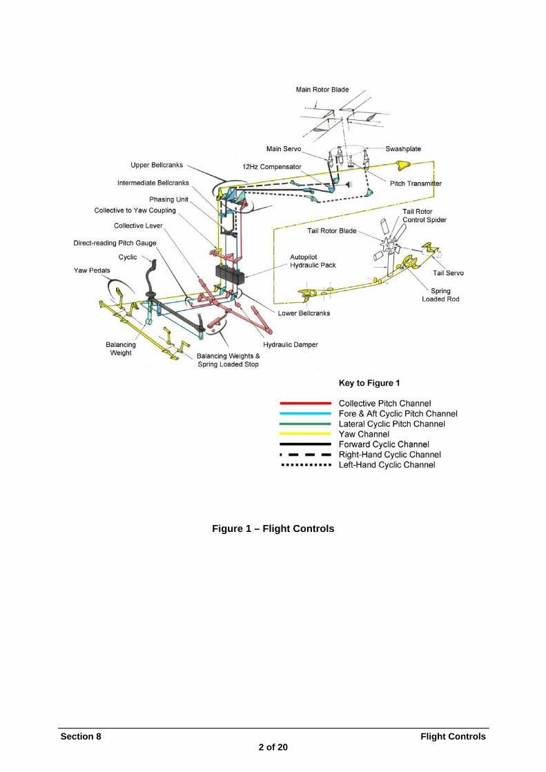
Figure 1 – Flight Controls
Section 8 Flight Controls 2 of 20
Main Rotor
Section 8 Flight Controls 3 of 20
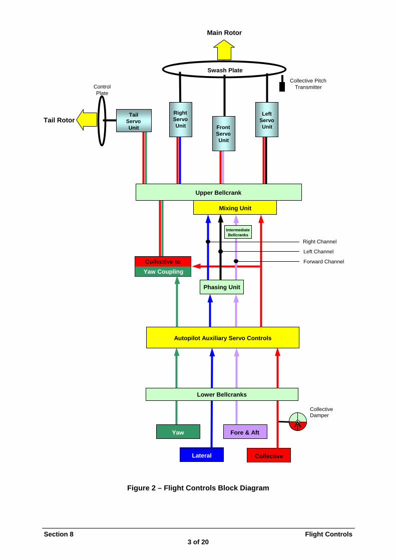
Figure 2 – Flight Controls Block Diagram
Swash PlateCollective Pitch
Control Transmitter Plate
RightTail LeftTail Rotor ServoServo Servo
UnitUnit UnitFrontServoUnit
Upper Bellcrank
Mixing Unit
Fore & AftYaw
Lateral Collective
IntermediateBellcranks
Right Channel
Left Channel
Collective to Forward Channel
Yaw Coupling
Phasing Unit
Autopilot Auxiliary Servo Controls
Lower Bellcranks
Collective Damper

FLYING CONTROLS General Variation of the main and tail rotor blades pitch is achieved by hydraulically operated servo-controls units attached to the Swashplate and tail rotor spider. These servo-control units are dual bodied with each body being supplied by a separate hydraulic system for safety. Movement of the servo controls is controlled by a distributor valve on each body connected via a series of push-pull rods and bell-crank levers to the pilots controls in the cockpit. The tail servo control run includes a cable operated portion along the tail boom. Fitted into the control runs, in the Flying Control Cabinet (Broom Cupboard), is the Autopilot Hydraulic unit, which assists the pilot in moving the controls, and provides an artificial 'feel'. This unit can move the controls, with no input from pilots, when directed by electrical signals from the Autopilot computer unit. The Captain and Co-pilot's controls in the cockpit consist of collective lever, cyclic lever and yaw pedals. These are coupled together by torque tubes under the cockpit floor. Any movement of these controls is transmitted by rods to the lower bell-crank assembly at the bottom of the Broom Cupboard. Secondary travel limit stops are fitted to the torque tubes, the primary stops being at the inputs to the Autopilot Hydraulic Unit. A general layout of the flight controls is shown in Figure 1 with a block diagram of the controls system in Figure 2. CYCLIC CONTROLS The cyclic levers give Longitudinal and Lateral movement inputs to the lower bell cranks and thence, through the Autopilot Hydraulic unit to the Phasing unit. See Figure 3. The Phasing unit is a gimbal mounted ‘mini swashplate’ receiving lateral and longitudinal inputs at 90° to each other, which cause it to pivot about the XX & YY axes. These axes correspond to the swashplate tilting axes for lateral and longitudinal rotor disc movement. Three output rods, spaced 120° apart, transmit this movement to their individual bellcranks on the mixing unit and then to the three main servo control distributors via rods and bellcranks under the transmission deck.
Section 8 Flight Controls 4 of 20
1. Yaw bell-crank 2. Phasing unit mount 3. Forward servo control rod 4. Left-hand servo control rod 5. Fore and aft cyclic rod 6. Lateral cyclic rod 7. Phasing Unit 8. Universal Joint
2 3 1 Y
4
X
X`
8
5
7 6
Y`
Figure 3 – Phasing Unit
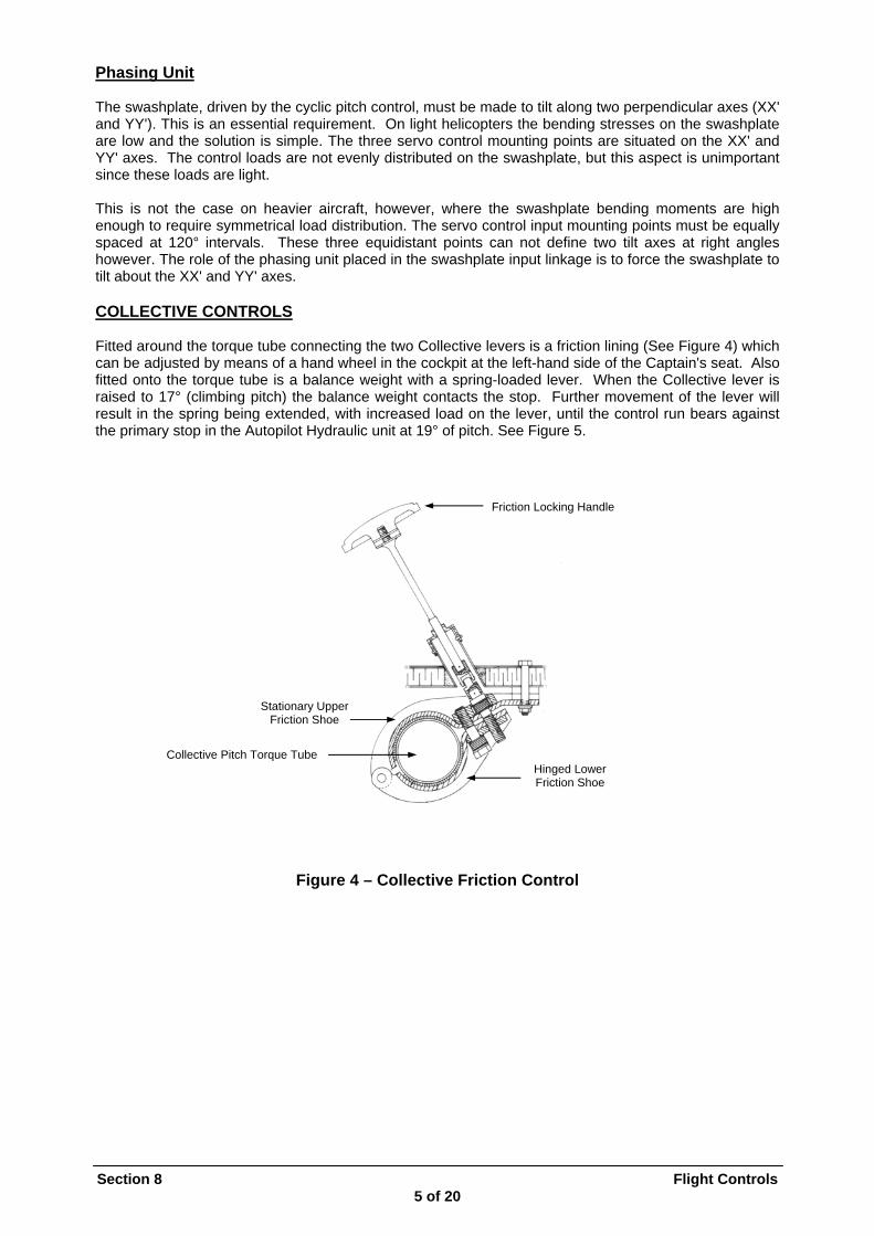
Phasing Unit The swashplate, driven by the cyclic pitch control, must be made to tilt along two perpendicular axes (XX' and YY'). This is an essential requirement. On light helicopters the bending stresses on the swashplate are low and the solution is simple. The three servo control mounting points are situated on the XX' and YY' axes. The control loads are not evenly distributed on the swashplate, but this aspect is unimportant since these loads are light. This is not the case on heavier aircraft, however, where the swashplate bending moments are high enough to require symmetrical load distribution. The servo control input mounting points must be equally spaced at 120° intervals. These three equidistant points can not define two tilt axes at right angles however. The role of the phasing unit placed in the swashplate input linkage is to force the swashplate to tilt about the XX' and YY' axes. COLLECTIVE CONTROLS Fitted around the torque tube connecting the two Collective levers is a friction lining (See Figure 4) which can be adjusted by means of a hand wheel in the cockpit at the left-hand side of the Captain's seat. Also fitted onto the torque tube is a balance weight with a spring-loaded lever. When the Collective lever is raised to 17° (climbing pitch) the balance weight contacts the stop. Further movement of the lever will result in the spring being extended, with increased load on the lever, until the control run bears against the primary stop in the Autopilot Hydraulic unit at 19° of pitch. See Figure 5.
Section 8 Flight Controls 5 of 20
Friction Locking Handle
Hinged Lower Friction Shoe
Sta er Friction Shoe
ube
tionary Upp
Collective Pitch Torque T
Figure 4 – Collective Friction Control

17º 19º Limited by Stationary Stop Limited by Internal Stop and Spring-Loaded lever in A er P Hydraulics Cylind
Fulcrum Weight & Stop Bracket
Section 8 Flight Controls 6 of 20
Fulcrum
Figure 5 – Collective Spring Loading Figure 5 – Collective Spring Loading In the event of the failure of the electrical pitch indicator the pitch can be checked on an indicator situated in the cockpit floor on the right-hand side of the centre console. This indicator is mechanically linked to the torque tube.
In the event of the failure of the electrical pitch indicator the pitch can be checked on an indicator situated in the cockpit floor on the right-hand side of the centre console. This indicator is mechanically linked to the torque tube. Attached to the lower bellcrank lever is a hydraulic damper to limit the rate of movement of the collective lever. This damper is simply a moving vane, which displaces fluid from one side to the other via a restricted orifice. See Figure 6.
Attached to the lower bellcrank lever is a hydraulic damper to limit the rate of movement of the collective lever. This damper is simply a moving vane, which displaces fluid from one side to the other via a restricted orifice. See Figure 6. Figure 6 – Collective Damper Figure 6 – Collective Damper
Spring-Loaded Stop Lever
Stationary Stop Spring
Balancing Weight (Counteracts tendency for lever to shift position)
Damping Adjusting Screw
rifice
alve
lug
ane
Filler P
A
Moving V
Interconnecting O
Check V
C B Fixed in Position
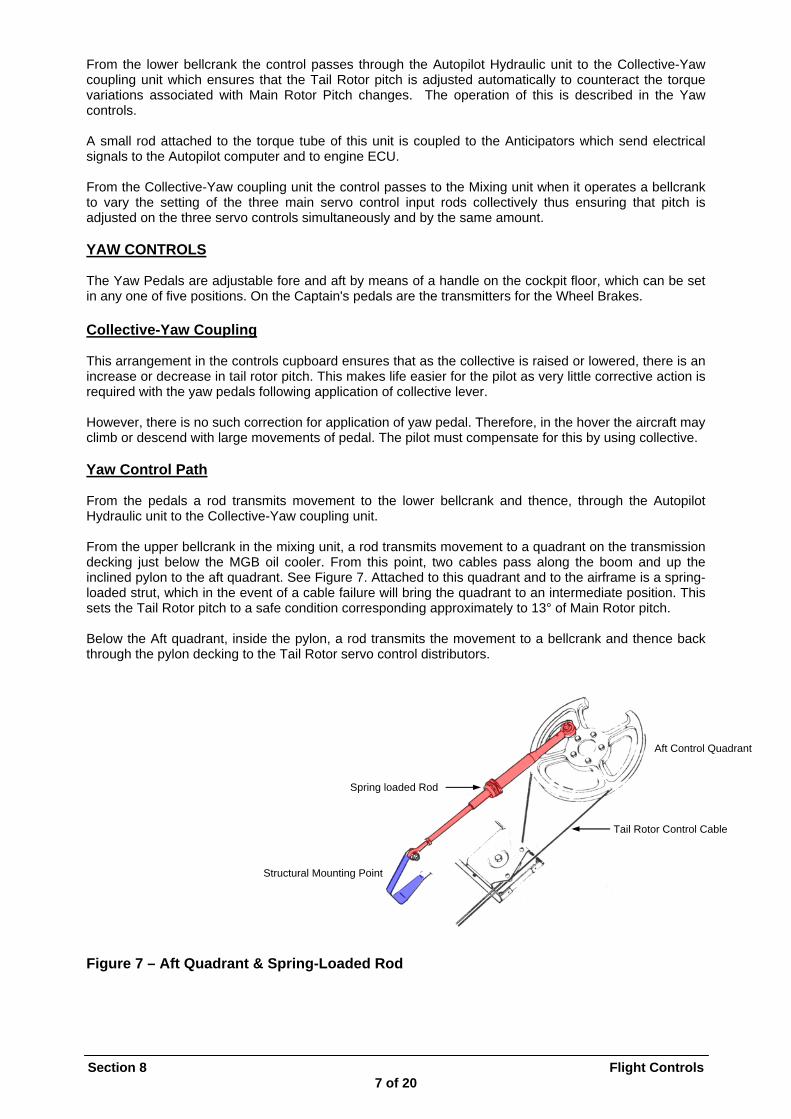
From the lower bellcrank the control passes through the Autopilot Hydraulic unit to the Collective-Yaw coupling unit which ensures that the Tail Rotor pitch is adjusted automatically to counteract the torque variations associated with Main Rotor Pitch changes. The operation of this is described in the Yaw controls. A small rod attached to the torque tube of this unit is coupled to the Anticipators which send electrical signals to the Autopilot computer and to engine ECU. From the Collective-Yaw coupling unit the control passes to the Mixing unit when it operates a bellcrank to vary the setting of the three main servo control input rods collectively thus ensuring that pitch is adjusted on the three servo controls simultaneously and by the same amount. YAW CONTROLS The Yaw Pedals are adjustable fore and aft by means of a handle on the cockpit floor, which can be set in any one of five positions. On the Captain's pedals are the transmitters for the Wheel Brakes. Collective-Yaw Coupling This arrangement in the controls cupboard ensures that as the collective is raised or lowered, there is an increase or decrease in tail rotor pitch. This makes life easier for the pilot as very little corrective action is required with the yaw pedals following application of collective lever. However, there is no such correction for application of yaw pedal. Therefore, in the hover the aircraft may climb or descend with large movements of pedal. The pilot must compensate for this by using collective. Yaw Control Path From the pedals a rod transmits movement to the lower bellcrank and thence, through the Autopilot Hydraulic unit to the Collective-Yaw coupling unit. From the upper bellcrank in the mixing unit, a rod transmits movement to a quadrant on the transmission decking just below the MGB oil cooler. From this point, two cables pass along the boom and up the inclined pylon to the aft quadrant. See Figure 7. Attached to this quadrant and to the airframe is a spring-loaded strut, which in the event of a cable failure will bring the quadrant to an intermediate position. This sets the Tail Rotor pitch to a safe condition corresponding approximately to 13° of Main Rotor pitch. Below the Aft quadrant, inside the pylon, a rod transmits the movement to a bellcrank and thence back through the pylon decking to the Tail Rotor servo control distributors. Aft Control Quadrant
Spring loaded Rod Tail Rotor Control Cable Structural Mounting Point Figure 7 – Aft Quadrant & Spring-Loaded Rod
Section 8 Flight Controls 7 of 20
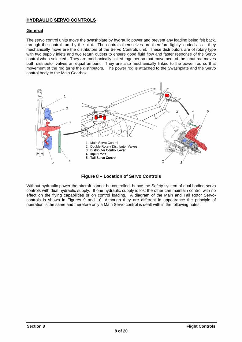
HYDRAULIC SERVO CONTROLSHYDRAULIC SERVO CONTROLS General The servo control units move the swashplate by hydraulic power and prevent any loading being felt back, through the control run, by the pilot. The controls themselves are therefore lightly loaded as all they mechanically move are the distributors of the Servo Controls unit. These distributors are of rotary type with two supply inlets and two return outlets to ensure good fluid flow and faster response of the Servo control when selected. They are mechanically linked together so that movement of the input rod moves both distributor valves an equal amount. They are also mechanically linked to the power rod so that movement of the rod turns the distributors. The power rod is attached to the Swashplate and the Servo control body to the Main Gearbox. 1
2 4 5 3 3
Section 8 Flight Controls 8 of 20
4 2
1. Main Servo Control
2. Double Rotary Distributor Valves 3. Distributor Control Lever 3. Distributor Control Lever 4. Input Rods 4. Input Rods
5. Tail Servo Control 5. Tail Servo Control 2 2
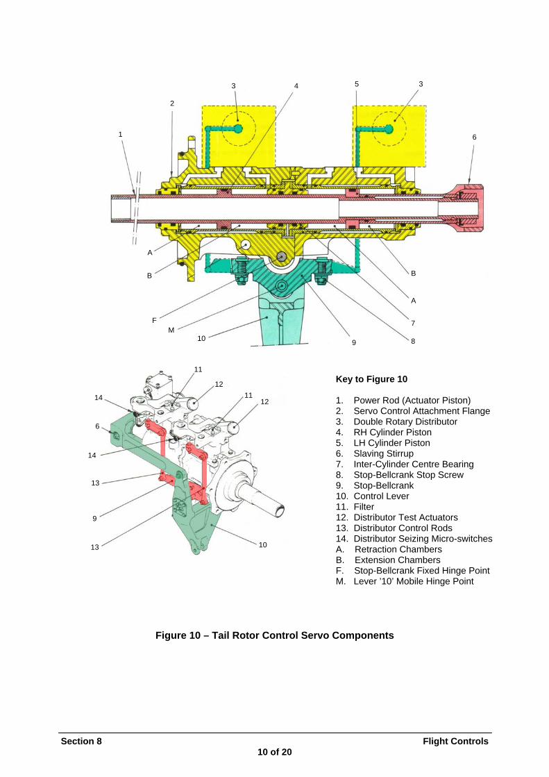
Figure 8 – Location of Servo Controls Without hydraulic power the aircraft cannot be controlled, hence the Safety system of dual bodied servo controls with dual hydraulic supply. If one hydraulic supply is lost the other can maintain control with no effect on the flying capabilities or on control loading. A diagram of the Main and Tail Rotor Servo-controls is shown in Figures 9 and 10. Although they are different in appearance the principle of operation is the same and therefore only a Main Servo control is dealt with in the following notes.

Section 8 Flight Controls 9 of 20
1
15 2
3 16
4 A 17
5 14 18
5 B 6 19
7 6 13
Mobile Hinge Point
Fixed Hinge Point 7 A 8 21
12 20
9 B 10
10 11
Figure 9 – Main Rotor Control Servo Components
Key to Figure 9 1. Ball-end fitting 13. Centre inter-cylinder bearing 2. Power Rod (actuator piston) 14. Upper cylinder piston 3. Actuator cylinder 15. Distribution slaving stirrup 4. Upper cylinder distribution module 16. Distributor seizing detector 5. Upper cylinder double rotary distributor 17. Seizing indicator micro-switch 6. Thrust lever 18. Filter 7. Distribution control lever 19. Upper distributor test actuator 8. Stop screw 20. Lower distributor test actuator 9. Lower cylinder distribution module 21. Distributor control link 10. Lower cylinder double rotary distributor 11. Ball-end fitting (attachment to MGB) A. Retraction Chamber 12. Lower cylinder piston B. Extension Chamber
Section 8 Flight Controls 10 of 20
1
2
3 4 5 3
6
A B B A F 7
M 10
9
13
11
12 11
12
10
8 9 Key to Figure 10
1. Power Rod (Actuator Piston) 2. Servo Control Attachment Flange 3. Double Rotary Distributor 4. RH Cylinder Piston 5. LH Cylinder Piston 6. Slaving Stirrup 7. Inter-Cylinder Centre Bearing 8. Stop-Bellcrank Stop Screw 9. Stop-Bellcrank 10. Control Lever 11. Filter 12. Distributor Test Actuators 13. Distributor Control Rods 14. Distributor Seizing Micro-switches A. Retraction Chambers B. Extension Chambers F. Stop-Bellcrank Fixed Hinge Point M. Lever ’10’ Mobile Hinge Point
14
6
14 13
Figure 10 – Tail Rotor Control Servo Components
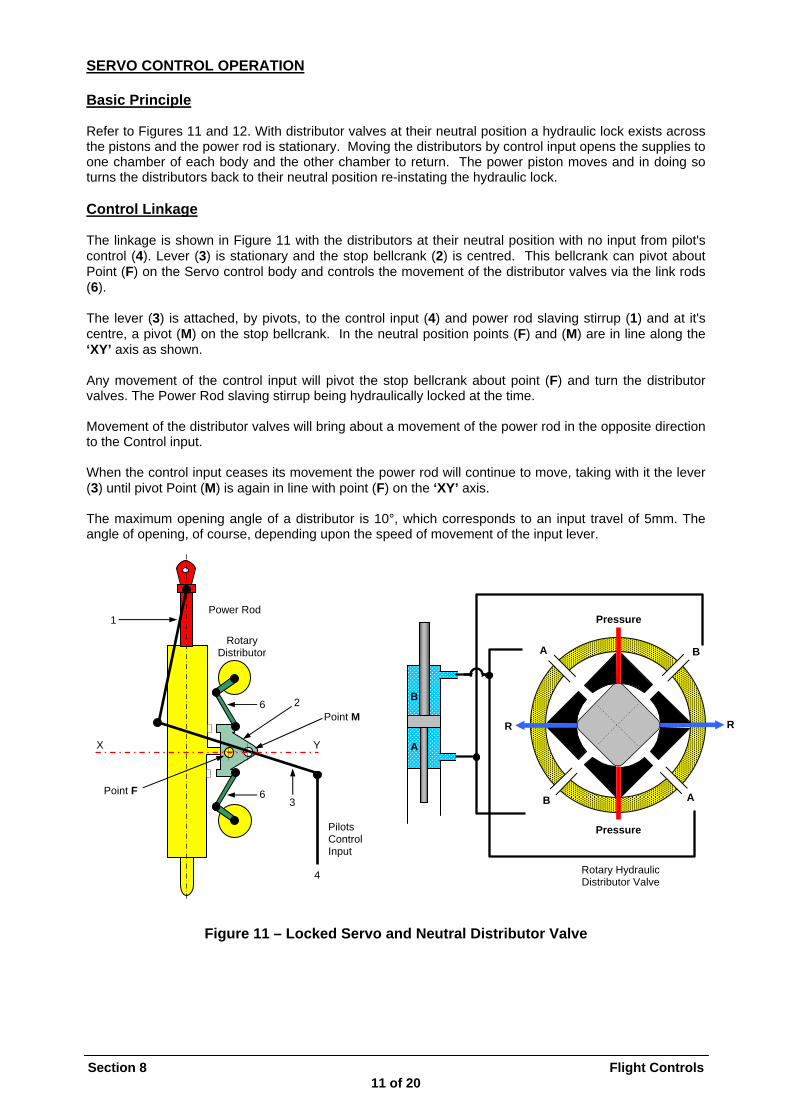
SERVO CONTROL OPERATION Basic Principle Refer to Figures 11 and 12. With distributor valves at their neutral position a hydraulic lock exists across the pistons and the power rod is stationary. Moving the distributors by control input opens the supplies to one chamber of each body and the other chamber to return. The power piston moves and in doing so turns the distributors back to their neutral position re-instating the hydraulic lock. Control Linkage The linkage is shown in Figure 11 with the distributors at their neutral position with no input from pilot's control (4). Lever (3) is stationary and the stop bellcrank (2) is centred. This bellcrank can pivot about Point (F) on the Servo control body and controls the movement of the distributor valves via the link rods (6). The lever (3) is attached, by pivots, to the control input (4) and power rod slaving stirrup (1) and at it's centre, a pivot (M) on the stop bellcrank. In the neutral position points (F) and (M) are in line along the ‘XY’ axis as shown. Any movement of the control input will pivot the stop bellcrank about point (F) and turn the distributor valves. The Power Rod slaving stirrup being hydraulically locked at the time. Movement of the distributor valves will bring about a movement of the power rod in the opposite direction to the Control input. When the control input ceases its movement the power rod will continue to move, taking with it the lever (3) until pivot Point (M) is again in line with point (F) on the ‘XY’ axis. The maximum opening angle of a distributor is 10°, which corresponds to an input travel of 5mm. The angle of opening, of course, depending upon the speed of movement of the input lever.
Section 8 Flight Controls 11 of 20
Figure 11 – Locked Servo and Neutral Distributor Valve
Pilots Control Input
X Y
1
2
6
6
3
Point M
Point F
Rotary Distributor
Rotary Hydraulic Distributor Valve
B A
Pressure
Pressure
R R
B
B A
A
Power Rod
4

Pressure
Pressure
Rotary Hydraulic Distributor Valve
A B
Pilots Control Input
X Y
1
2
6
6
3
Point M
Point F
Rotary Distributor
R R
Figure 12 – Moving Servo with Moving Distributor Valve DOUBLE HYDRAULIC ROTARY DISTRIBUTOR VALVES Operating Principle If no safety provision were included, the seizing of a distributor valve would jam the corresponding flight control linkage and make the rotors almost impossible to control. The double distributor valve prevents the control from jamming and continues to supply the servo control in the event of a valve seizing. The unit comprises two coaxial valves as shown in Figure 13.
The Main distributor valve (1) The Secondary back-up distributor valve (2)
Section 8 Flight Controls 12 of 20
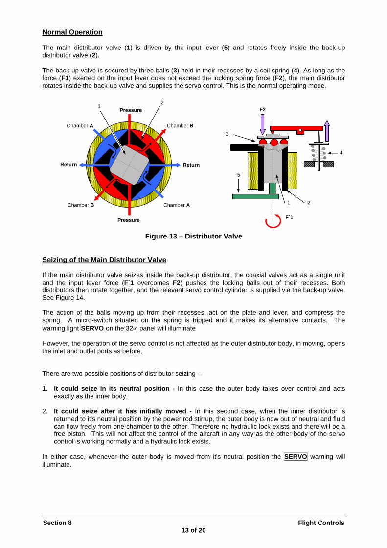
Normal Operation The main distributor valve (1) is driven by the input lever (5) and rotates freely inside the back-up distributor valve (2). The back-up valve is secured by three balls (3) held in their recesses by a coil spring (4). As long as the force (F1) exerted on the input lever does not exceed the locking spring force (F2), the main distributor rotates inside the back-up valve and supplies the servo control. This is the normal operating mode. 2
Section 8 Flight Controls 13 of 20
3
4
F2
2 1
5
F`1
Return
Chamber B Chamber A
Pressure
Pressure
Return
Chamber A Chamber B
1
Figure 13 – Distributor Valve Seizing of the Main Distributor Valve If the main distributor valve seizes inside the back-up distributor, the coaxial valves act as a single unit and the input lever force (F`1 overcomes F2) pushes the locking balls out of their recesses. Both distributors then rotate together, and the relevant servo control cylinder is supplied via the back-up valve. See Figure 14. The action of the balls moving up from their recesses, act on the plate and lever, and compress the spring. A micro-switch situated on the spring is tripped and it makes its alternative contacts. The warning light SERVO on the 32∝ panel will illuminate However, the operation of the servo control is not affected as the outer distributor body, in moving, opens the inlet and outlet ports as before. There are two possible positions of distributor seizing – 1. It could seize in its neutral position - In this case the outer body takes over control and acts
exactly as the inner body. 2. It could seize after it has initially moved - In this second case, when the inner distributor is
returned to it's neutral position by the power rod stirrup, the outer body is now out of neutral and fluid can flow freely from one chamber to the other. Therefore no hydraulic lock exists and there will be a free piston. This will not affect the control of the aircraft in any way as the other body of the servo control is working normally and a hydraulic lock exists.
In either case, whenever the outer body is moved from it's neutral position the SERVO warning will illuminate.

Section 8 Flight Controls 14 of 20
Main Distributor Valve Seized ‘Open’ Main Distributor Valve Seized ‘Closed’
eturn
Figure 14 – Distributor Valve Failure
R
Chamber B Chamber A
Pressure
Pressure
Return
A Chamber B Chamber
Return
Chamber B Chamber A
Pressure
Pressure
Return
Chamber A Chamber B
SERVO SERVO
F`1
1 2 3 4 5 6
7 8 9
10 To Distributor
Valve
1
2
3
4 5
7 8
9
10
Section 8 Flight Controls 15 of 20
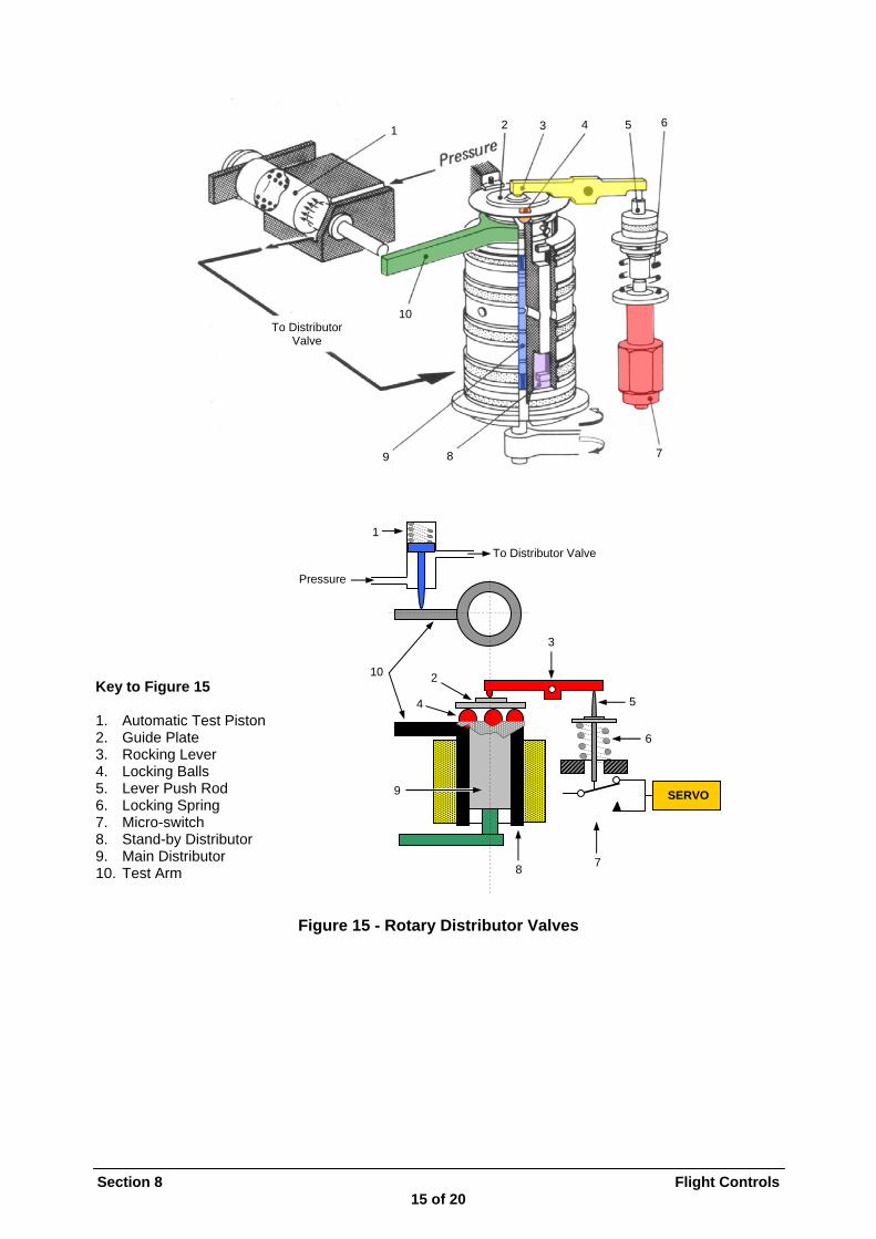
Key to Figure 15 1. Automatic Test Piston 2. Guide Plate 6
Pressure
To Distributor Valve
3. Rocking Lever 4. Locking Balls 5. Lever Push Rod SERVO 6. Locking Spring 7. Micro-switch 8. Stand-by Distributor 9. Main Distributor 10. Test Arm
Figure 15 - Rotary Distributor Valves

Automatic Test Facility Refer to Figure 16. To ensure that the outer distributor valves will move when necessary an automatic testing facility is provided. This consists of a spring-loaded test piston (1), contacting the arm on top of the outer distributor body, which is supplied with hydraulic pressure whenever the servo control is supplied. When hydraulic pressure is applied the piston is retracted against the spring (R) and the outer body is in its neutral position. If hydraulic pressure fails, the spring extends the piston, the outer body is turned and the micro-switch tripped. Thus, prior to start up, with no hydraulic pressure, all eight outer bodies (8) are turned and all micro-switches are on their ‘seized’ contacts. When pressure builds up, the piston retracts and the spring-loaded lever pushes the balls down into their recesses, turning the outer body back to its neutral position.
Section 8 Flight Controls 16 of 20
Figure 16- Automatic Test Facility Electrical Warning System The Amber SERVO warning light on the 32∝ panel is controlled by the 8 detector micro-switches on the distributors, which are wired in series to form a monitoring loop. Diodes ensure current will only flow in one direction. A Zener diode (2) in conjunction with a transistor (1) form the switching arrangement to put he light ‘ON' or 'OFF'. A Zener diode will allow current to flow in reverse direction when the supply voltage is greater than its designed breakdown voltage. A Test button is provided on the 34∝ panel to allow the circuit to be tested both prior to start up and after start up. The following paragraphs look at the electrical circuitry of the servo warning system.
SERVO
Zero Pressure R
1
8
8
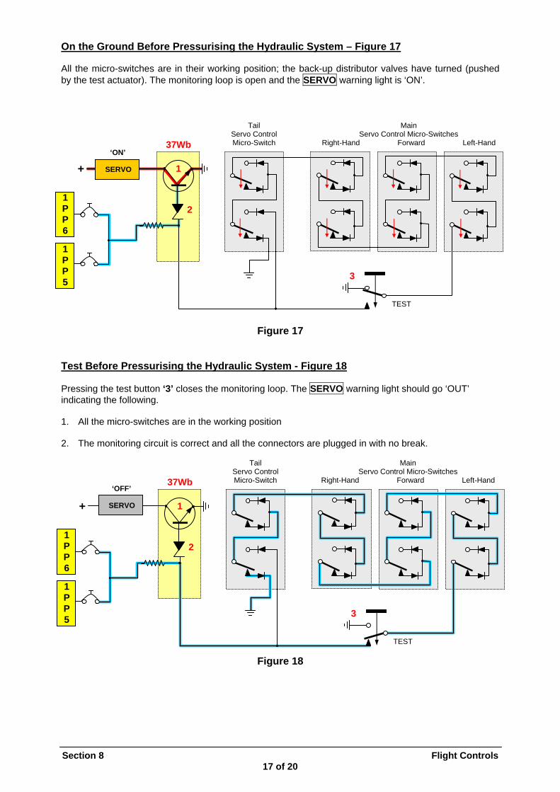
On the Ground Before Pressurising the Hydraulic System – Figure 17 All the micro-switches are in their working position; the back-up distributor valves have turned (pushed by the test actuator). The monitoring loop is open and the SERVO warning light is ‘ON’. Tail Main
Section 8 Flight Controls 17 of 20
Figure 17 Test Before Pressurising the Hydraulic System - Figure 18 Pressing the test button ‘3’ closes the monitoring loop. The SERVO warning light should go ‘OUT’ indicating the following. 1. All the micro-switches are in the working position 2. The monitoring circuit is correct and all the connectors are plugged in with no break.
Figure 18
Servo Control Mi h
Servo Control Micro-Switches cro-Switc Right-Hand Forward Left-Hand 37Wb
‘ON’
+
1 P P 6
1 P P 5
1
2
SERVO
3
TEST
Tail Main Servo Control Mi h
Servo Control Micro-Switches cro-Switc Right-Hand Forward Left-Hand 37Wb
‘OFF’
+ 1 SERVO
1 P 2 P 6
1 P P 3 5
TEST
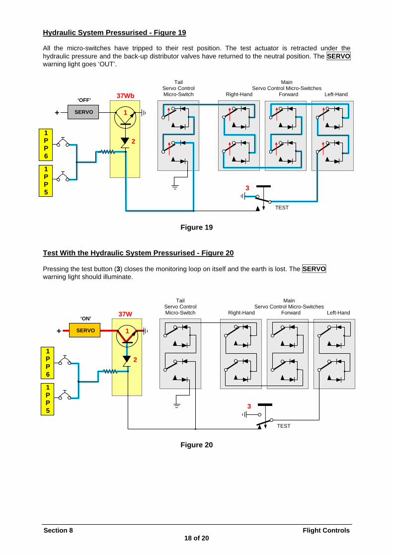
Hydraulic System Pressurised - Figure 19 All the micro-switches have tripped to their rest position. The test actuator is retracted under the hydraulic pressure and the back-up distributor valves have returned to the neutral position. The SERVO warning light goes ‘OUT’. Tail Main
Section 8 Flight Controls 18 of 20
Figure 19 Test With the Hydraulic System Pressurised - Figure 20 Pressing the test button (3) closes the monitoring loop on itself and the earth is lost. The SERVO warning light should illuminate.
Figure 20
Servo Control Mi h
Servo Control Micro-Switches cro-Switc Right-Hand Forward Left-Hand 37Wb
‘OFF’
+
1 P P 6
1 P P 5
1 SERVO
2
3
TEST
Tail Main Servo Control Mi h
Servo Control Micro-Switches cro-Switc Right-Hand Forward Left-Hand 37W
‘ON’
+
1 P P 6
1 P P 5
1 SERVO
2
3
TEST

Seizure of a Distributor Valve – Figure 21 Should one of the distributor valve seize the corresponding micro-switch will be tripped to its ‘work’ position and the monitoring loop is broken. The SERVO warning light will illuminate. Note that the SERVO light will also illuminate under the following circumstances – 1. When the Left-Hand or Right-Hand Hydraulic System fluid level drops causing automatic isolation of
the Tail Servo Control 2. With a drop in the Left-Hand or Right-Hand Hydraulic System pressure. 3. On the ground when operating on battery only as the automatic isolation of the Tail Servo Control
Left-Hand cylinder takes place.
Tail Main Servo Control Mi h
Servo Control Micro-Switches cro-Switc Right-Hand Forward Left-Hand 37Wb ‘ON’
Section 8 Flight Controls 19 of 20
Figure 21
+
1 P P 6
1 P P 5
1 SERVO
2
3 Seizing
TEST

Section 8 Flight Controls 20 of 20
INTENTIONALLY BLANK